Embed Size (px)
Citation preview

INSTALLATION INSTRUCTIONS
installation instructions 1
By CityScapes International, Incorporated4200 Lyman Court, Hilliard, OH 43026
Phone: 614.850.2549, Fax: 614.850.2553, Toll Free: 877.727.3367www.cityscapesinc.comU.S. PATENT NO. 5,664,384
CSII DI100565 2/06
Vertical Style Rooftop Equipment Screens
Design and AssemblyEnvisor components are designed to function as an Equipment Screening System.“Modular by Design” allows for a more user-friendly installation. This instruction packet isintended to communicate the “typical” Envisor screen installation. As you will see in thefollowing pages, rooftop units (RTUs) vary greatly in size, performance accessories, andpower supply requirements. Each screen ships as a knockdown assembly, with projectspecific parts lists and instruction supplements. Please review these pages carefully. Weencourage you to call, fax or e-mail your questions and thank you for your interest inEnvisor equipment screens.
Bottom Rail
Flat Ribbed Plastic Panel
Top Trim (T.T.)- optional -
Top Rail RTU unit
Corner Truss
Midspan Truss
U.S. PATENT NO. 5,664,384U.S. PATENT NO. 7,000,362U.S. PATENT NO. 7,707,798

INSTALLATION INSTRUCTIONS
Typical Installation of a 10 ton HVAC RTU
A)
B) B)C)
10”
U.S. PATENT NO. 5,664,384
By CityScapes International, Incorporated4200 Lyman Court, Hilliard, OH 43026
Phone: 614.850.2549, Fax: 614.850.2553, Toll Free: 877.727.3367www.cityscapesinc.com
Vertical Style Rooftop Equipment Screens
RTUs Installation VariablesRooftop units (RTUs) are manufactured in a wide variety of sizes and shapes, with manydifferent applications. Typically the project’s architect, mechanical contractor or buildingowner will have exact information on the HVAC equipment manufacturer(s) specified,i.e. Aaon, Carrier, Hussman, Lennox, Trane, York, etc. A common point of reference toidentify the physical size of the RTU equipment involved is “tonnage”, i.e. 3-4 ton unit ora 75 ton unit.
Additional variables to be considered when screening a RTU with Envisor componentshave been depicted below. As with most field-installed products, the most completeinformation in the bid process will minimize any surprises during actual installation.
A). Electrical Disconnect Boxposition should allow for a 1.5”minimum set back from thecabinet’s corner.
B). Supply lines such as Gas andElectric need to be installedas close to the roof deck as possible.
C). Average Curb height above theroof deck is approximately 10”.Curb heights more or less than thisrange should be noted andcommunicated.
A)
B) B)C)
10”
Typical Cabinet Drip Edge Condition
Most RTU cabinets will have a fabricateddrip edge for rain at the top of the unit.Any accessories or obstructions other thanthis typical condition shown should benoted.(Compare to non-typical drip edgecondition below)
installation instructions 2
U.S. PATENT NO. 5,664,384U.S. PATENT NO. 7,000,362U.S. PATENT NO. 7,707,798

INSTALLATION INSTRUCTIONS
U.S. PATENT NO. 5,664,384
By CityScapes International, Incorporated4200 Lyman Court, Hilliard, OH 43026
Phone: 614.850.2549, Fax: 614.850.2553, Toll Free: 877.727.3367www.cityscapesinc.com
34”
Vertical Style Rooftop Equipment Screens
RTUs Installation Variables, continued
34”
Economizer with Power Exhaust
The maximum distance that acorner truss can accomodate is 34”without additional support bracing.
Note: The images and conditions shown on pages 2 and 3 are representative of some potential variations thatcould effect the installation of an Envisor screen. Ultimately, any additional costs to accommodate condtionsor equipment accessories that may require field modifications to Envisor components that were not anticipatedwill not be the responsibility of CityScapes International, Incorporated.
installation instructions 3
U.S. PATENT NO. 5,664,384U.S. PATENT NO. 7,000,362U.S. PATENT NO. 7,707,798
INSTALLATION INSTRUCTIONS
U.S. PATENT NO. 5,664,384
By CityScapes International, Incorporated4200 Lyman Court, Hilliard, OH 43026
Phone: 614.850.2549, Fax: 614.850.2553, Toll Free: 877.727.3367www.cityscapesinc.com
Vertical Style Rooftop Equipment Screens
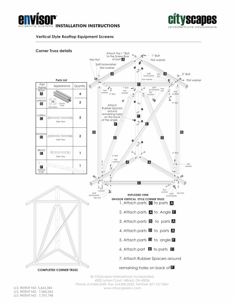
Corner Truss details
End View
Screwboss
PartName Appearance Quantity
4
2
2
2
1
1
BEAM
UPRIGHT
LATERAL
DIAGONAL
BRACE
ANGLEPOST
5454
Side View
Side View
0603
30 30
Parts List
Side View
1. Attach parts to parts
2. Attach parts to Angle
3. Attach parts to parts
4. Attach parts to parts
5. Attach parts to angle
6. Attach part to parts
7. Attach Rubber Spacers around
remaining holes on back of
EXPLODED VIEWENVISOR VERTICAL STYLE CORNER TRUSS
COMPLETED CORNER TRUSS
C
Top
Attach the 1 ”Boltto the Screw Boss
of part A
AttachRubber Spacers
aroundremaining holes
on the backof the angle .
Flat washerSplit lockwasher
Hex Nut
30
45
30
45
30
30
60
4545
60
1” BoltFlat washer
Flat washer
2” Bolt
1” BoltFlat
washer
Splitlockwasher
Flat washer
HexNut
HexNut
SplitlockwasherFlat
washer
Flatwasher Flat
washer
2” Bolt
Hex NutFlat
washerSplit
lockwasher
2” Bolt
Flatwasher
2” Bolt
Flatwasher
Hex Nut
Splitlockwasher
Flatwasher
2” Bolt
installation instructions 4
U.S. PATENT NO. 5,664,384U.S. PATENT NO. 7,000,362U.S. PATENT NO. 7,707,798

INSTALLATION INSTRUCTIONS
U.S. PATENT NO. 5,664,384
By CityScapes International, Incorporated4200 Lyman Court, Hilliard, OH 43026
Phone: 614.850.2549, Fax: 614.850.2553, Toll Free: 877.727.3367www.cityscapesinc.com
EXPLODED VIEW
Attach the 1 ”Boltto the Screw Boss
of part A
Top
30
60
AttachRubber Spacers
aroundremaining holes
on the backof the angle .
Flat washer
2” Bolt
Flat washer1” Bolt
Hex nut
Splitlockwasher
Flatwasher
Flatwasher
Hex nutSplitlockwasher
Flatwasher
2” Bolt
Flatwasher
Vertical Style Rooftop Equipment Screens
Midspan Truss details
COMPLETEDMIDSPAN TRUSS
ANGLEPOST
BEAM
UPRIGHT
DIAGONAL
PartName Appearance Quantity
2
1
1
1
0603
Side View
Parts List
End ViewScrewboss
1. Attach parts to Angle
2. Attach part to parts
3. Attach part to part
4. Attach part to angle
5. Attach Rubber Spacers around
remaining holes on back of
installation instructions 5
U.S. PATENT NO. 5,664,384U.S. PATENT NO. 7,000,362U.S. PATENT NO. 7,707,798

INSTALLATION INSTRUCTIONS
U.S. PATENT NO. 5,664,384
By CityScapes International, Incorporated4200 Lyman Court, Hilliard, OH 43026
Phone: 614.850.2549, Fax: 614.850.2553, Toll Free: 877.727.3367www.cityscapesinc.com
Vertical Style Rooftop Equipment Screens
Getting Started
1. If there are multiple RTUs, be sure to match the correct Envisor screening componentsto the appropriate equipment. Component cartons will be labled with a Sales Order No.,and the RTU’s Manufacturer, with the Model No. of the RTU on which they are designatedto be installed.
2. All units have there own layout drawings included with the installation instructions. Reviewthe RTU’s Adjacent Perimeter Area for obstructions or supply lines that may engage thescreening components during installation. If our Design Engineers made allowances forany field conditions prior to shipment, the Job Specific installation instructions will identifyany Equipment Specific Midspans or Extensions for your Envisor screen(s).
3. Locate the cartons marked “Corner Truss Kit”. These items have been sent as a “KnockdownKit” and will require field assembly prior to the installation of other Envisor components.
4. Check the RTU for “Square” and “Level” before proceeding to Step 1 on the followingpage.
Required ToolsLevelTape MeasureFraming SquareCordless DrillPower Miter Saw
Reciprocating Saw (with metal cutting blades)#5/16” Drill Socket (nut driver)3/8” Combination Wrench7/16” Combination WrenchQuick Clamps (optional)
3/8” Socket7/16” Socket1/8” Drill Bit5/16” Drill Bit
Envisor ComponentsTopRail
BottomRail
CornerTrussExtrusion
TopTrim
installation instructions 6
U.S. PATENT NO. 5,664,384U.S. PATENT NO. 7,000,362U.S. PATENT NO. 7,707,798

INSTALLATION INSTRUCTIONS
installation instructions 7
U.S. PATENT NO. 5,664,384
By CityScapes International, Incorporated4200 Lyman Court, Hilliard, OH 43026
Phone: 614.850.2549, Fax: 614.850.2553, Toll Free: 877.727.3367www.cityscapesinc.com
Vertical Style Rooftop Equipment Screens
Step 1: Corner Truss
After verifying you have the correct Corner Truss for this RTU, review the Unit Specificinstallation instructions for additional Extensions or Midspan Trusses that may be requiredfor this specific RTU. Be sure to install these components in the proper locations beforeattaching the Corner Trusses. See Extension & Gusset pictures below.
Extensions,Gussets, Midspan Trusses and Corner Trusses all attach to the RTU with stainlesssteel TEK screws provided in the Hardware Kit. The optimum vertical location for the Corner& Midspan Truss assemblies
NOTE: Use EXTREME CAUTION when attaching these first components to the RTU with thestainless steel TEK screws.
Some equipment may have mechanical operating elements directly behing the areasyou are about to drive a screw into (i.e. condensing coils, etc.)Be absolutely sure that you are not about to penetrate any of these elements, or impedeany access to Service Doors or Disconnec t Switches.
Reference photos below and on next page.
GUSSET INSTALLATIONEXTENSION INSTALLATION
is to give maximum coverage, which is typically flush with the top of the RTU. This distance between bottom of screen and roof top will vary depending on the equipment’s curb height and allowances for perimeter obstructions. Be sure to level each component to the other as installation progresses around the perimeter of the RTU. See leveling picture.
U.S. PATENT NO. 5,664,384U.S. PATENT NO. 7,000,362U.S. PATENT NO. 7,707,798

INSTALLATION INSTRUCTIONS
U.S. PATENT NO. 5,664,384
By CityScapes International, Incorporated4200 Lyman Court, Hilliard, OH 43026
Phone: 614.850.2549, Fax: 614.850.2553, Toll Free: 877.727.3367www.cityscapesinc.com
LEVELING THE COMPONENTS
CORNER TRUSS INSTALLATION
installation instructions 8
U.S. PATENT NO. 5,664,384U.S. PATENT NO. 7,000,362U.S. PATENT NO. 7,707,798

INSTALLATION INSTRUCTIONS
U.S. PATENT NO. 5,664,384
By CityScapes International, Incorporated4200 Lyman Court, Hilliard, OH 43026
Phone: 614.850.2549, Fax: 614.850.2553, Toll Free: 877.727.3367www.cityscapesinc.com
Flush withextrusion,Checkangle withSquareandattachhere.
Flush withextrusion,Checkangle withSquareandattachhere.
Vertical Style Rooftop Equipment Screens
Step 2: Install Bottom Rail (B.R.)Temporarily position all of the bottom rail as indicated in the diagram below. If any of thedimensions on your RTU are longer than the longest B.R., you will need to splice two lengthstogether. See Detail A on next page.
Beginning at one corner, use a framing square to align B.R. to the installed Corner Truss onthe RTU. This first end of the B.R. should be flush and square with the Corner Truss. Assurethe alignment and placement of the rail in respect to the pilot hole located in the centerof the extrusion on the Corner Truss leg. Mark this location and drill a hole with the 5/16"drill bit. Using 1/4"-20 x 1" self tapping screw, fasten through B.R. into the Corner Truss legextrusion pilot hole. See illustration and detail photo below.
Continue installing the B.R. at alternating legs of the Corner Truss around the perimeter ofthe RTU, making sure each Corner Truss is square to the B.R. before drilling and fastening.Install the remaining four corners as above, additionally checking the lengths of the B.R.on the opposing side of the RTU for equal distances. Then cut the excess lengths of theB.R. with a reciprocating saw. See Detail B on next page.
After all four corners have been trimmed, insert the Corner Splice (appx. 6” length ofextrusion) into the bottom “C” cavity of the B.R. Secure the Corner Splice in place with the 1 1/4” TEK screws. See Detail C on next page.
90° angle
Attach Here FirstFlush with extrusion, checkangle with square
Flush
Cut excessextrusionaftercheckingdistances(See Text)
Attach here only afterattaching all other B.R.sand checking fordescribed conditions(see text).
installation instructions 9
U.S. PATENT NO. 5,664,384U.S. PATENT NO. 7,000,362U.S. PATENT NO. 7,707,798

INSTALLATION INSTRUCTIONS
U.S. PATENT NO. 5,664,384
By CityScapes International, Incorporated4200 Lyman Court, Hilliard, OH 43026
Phone: 614.850.2549, Fax: 614.850.2553, Toll Free: 877.727.3367www.cityscapesinc.com
Detail A
After attaching B.R.scut excess extrusion(see detail B).
Step 2: Install Bottom Rail (B.R.) continued
Detail C
Check anglewithSquare andattachhere first.
END SECTION VIEW
1
BACK VIEW
TOP VIEW
4 2 3
3
5"
16"
2" 2" 5"
2 4 12500028 1/4"-20 X 2" LG HEX HD. BOLT
1 1 80000156 1 1/8" X 1 1/8" FRAME EXTRUSION 16" LG.
BILL OF MATERIAL
ITEM PART#REQ DESCRIPTION
3 8 12500007 1/4"-20 FLAT WASHER
4 4 12500006 1/4"-20 HEX NUT
B
Detail B
B
Front View
Back View
90° angle
Vertical Style Rooftop Equipment Screens
installation instructions 10
U.S. PATENT NO. 5,664,384U.S. PATENT NO. 7,000,362U.S. PATENT NO. 7,707,798

INSTALLATION INSTRUCTIONS
Step 3: Install Top Rail (T.R.)
U.S. PATENT NO. 5,664,384
By CityScapes International, Incorporated4200 Lyman Court, Hilliard, OH 43026
Phone: 614.850.2549, Fax: 614.850.2553, Toll Free: 877.727.3367www.cityscapesinc.com
Vertical Style Rooftop Equipment Screens
The Top Rail (T.R.) installs exactlythe same as the Bottom Rail.
It is important to maintain closetolerance cuts when fieldtrimming the B.R. and T.R. to insurethe Corner Splice fully engagesboth extrusions.
installation instructions 11
U.S. PATENT NO. 5,664,384U.S. PATENT NO. 7,000,362U.S. PATENT NO. 7,707,798

INSTALLATION INSTRUCTIONS
U.S. PATENT NO. 5,664,384
By CityScapes International, Incorporated4200 Lyman Court, Hilliard, OH 43026
Phone: 614.850.2549, Fax: 614.850.2553, Toll Free: 877.727.3367www.cityscapesinc.com
Vertical Style Rooftop Equipment Screens
Step 4: Place Stabilizer Braces
Place the Stabilizer Braces’s EndCasting over the central slot ofthe outer side of the bottom legof the Corner Truss. Slide EndCasting until the Brace’s oppositeend (no End Casting) is inside themounting slot of the B.R.Next, using a 5/16” drill bit, drillthrough both the End Casting ofBrace and bottom leg of CornerTruss and attach the parts withsupplied bolt using drilled hole asa guide (see Photo 1).
Then, lock the Stabilizing Bracein place by attaching it to theB.R. using a 1 1/4” Tek screw (drillfirst through the bottom of theB.R.’s mounting slot as shown inphotos 2 & 3).DO NOT BLOCK SERVICE DOORS.
1
2
Finally, place the other threeStabilizer Braces as shown below.
3
Bottom View of RTU with Stabilizer Braces in place
Use boltto attachBrace Castingto Corner Truss
B.R.
Corner Truss
StabilizerBraces
StabilizerBraces
CornerTruss
StabilizerBrace
StabilizerBrace
Attach brace to B.R.using a 1 1/4” longTEK screw
B.R.
StabilizerBrace
NOTE: Omit this step if unitis screened on 4 sides.
installation instructions 12
U.S. PATENT NO. 5,664,384U.S. PATENT NO. 7,000,362U.S. PATENT NO. 7,707,798
INSTALLATION INSTRUCTIONS
U.S. PATENT NO. 5,664,384
By CityScapes International, Incorporated4200 Lyman Court, Hilliard, OH 43026
Phone: 614.850.2549, Fax: 614.850.2553, Toll Free: 877.727.3367www.cityscapesinc.com
Top Trim Corner Angle
Splice
installation instructions 13
Top Rail (T.R.)
Top Trim (T.T.)
Cross Section
1 1/4” longstainless steel
TEK screw
Vertical Style Rooftop Equipment Screens
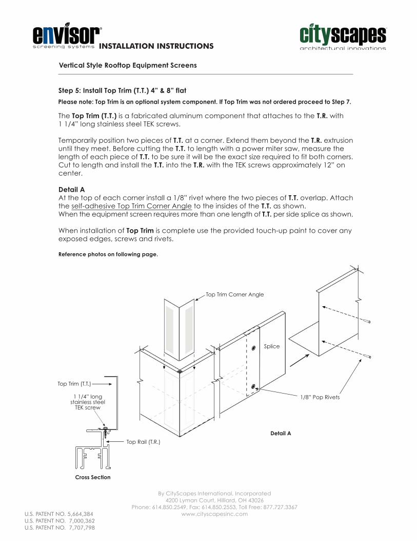
Step 5: Install Top Trim (T.T.) 4” & 8” flat
The Top Trim (T.T.) is a fabricated aluminum component that attaches to the T.R. with1 1/4” long stainless steel TEK screws.
Temporarily position two pieces of T.T. at a corner. Extend them beyond the T.R. extrusionuntil they meet. Before cutting the T.T. to length with a power miter saw, measure thelength of each piece of T.T. to be sure it will be the exact size required to fit both corners.Cut to length and install the T.T. into the T.R. with the TEK screws approximately 12” oncenter.
Detail AAt the top of each corner install a 1/8” rivet where the two pieces of T.T. overlap. Attachthe self-adhesive Top Trim Corner Angle to the insides of the T.T. as shown.When the equipment screen requires more than one length of T.T. per side splice as shown.
When installation of Top Trim is complete use the provided touch-up paint to cover anyexposed edges, screws and rivets.
Reference photos on following page.
Please note: Top Trim is an optional system component. If Top Trim was not ordered proceed to Step 7.
1/8” Pop Rivets
Detail A
U.S. PATENT NO. 5,664,384U.S. PATENT NO. 7,000,362U.S. PATENT NO. 7,707,798

INSTALLATION INSTRUCTIONS
U.S. PATENT NO. 5,664,384
By CityScapes International, Incorporated4200 Lyman Court, Hilliard, OH 43026
Phone: 614.850.2549, Fax: 614.850.2553, Toll Free: 877.727.3367www.cityscapesinc.com
Step 5: Install Top Trim (T.T.) 4” & 8” flat
Vertical Style Rooftop Equipment Screens
1/8” Pop Rivets
installation instructions 14
U.S. PATENT NO. 5,664,384U.S. PATENT NO. 7,000,362U.S. PATENT NO. 7,707,798
INSTALLATION INSTRUCTIONS
U.S. PATENT NO. 5,664,384
By CityScapes International, Incorporated4200 Lyman Court, Hilliard, OH 43026
Phone: 614.850.2549, Fax: 614.850.2553, Toll Free: 877.727.3367www.cityscapesinc.com
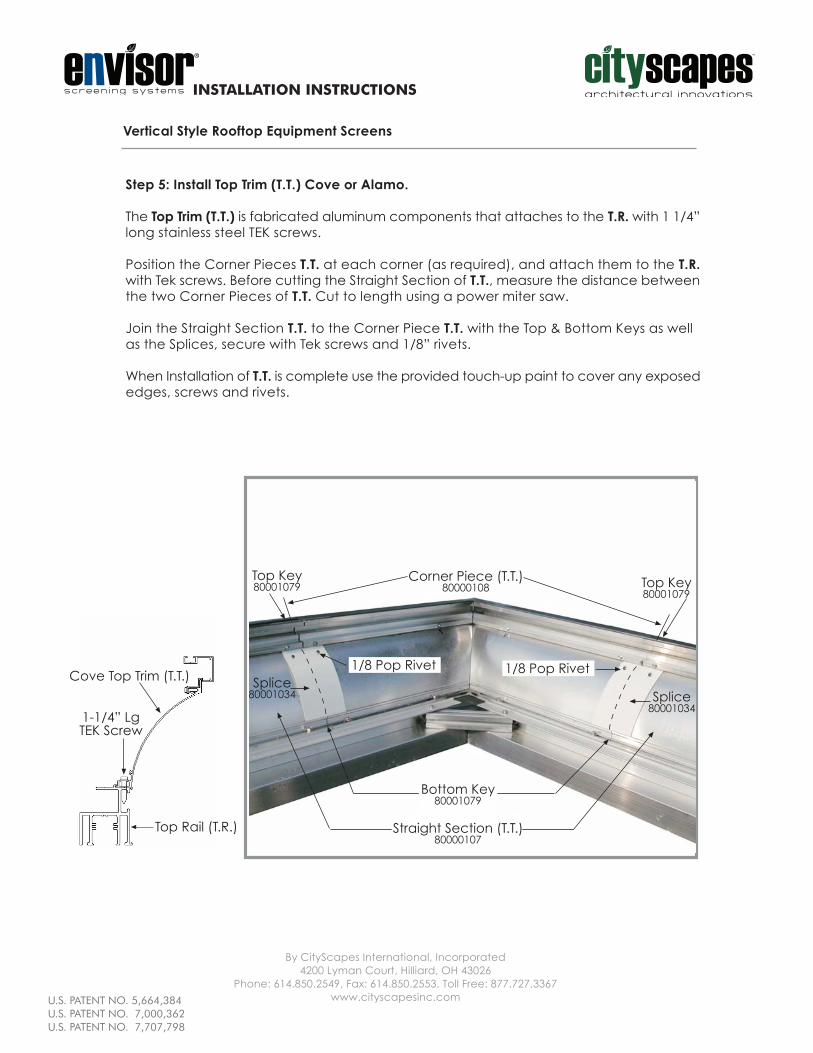
Step 5: Install Top Trim (T.T.) Cove or Alamo.
The Top Trim (T.T.) is fabricated aluminum components that attaches to the T.R. with 1 1/4”long stainless steel TEK screws.
Position the Corner Pieces T.T. at each corner (as required), and attach them to the T.R.with Tek screws. Before cutting the Straight Section of T.T., measure the distance betweenthe two Corner Pieces of T.T. Cut to length using a power miter saw.
Join the Straight Section T.T. to the Corner Piece T.T. with the Top & Bottom Keys as wellas the Splices, secure with Tek screws and 1/8” rivets.
When Installation of T.T. is complete use the provided touch-up paint to cover any exposededges, screws and rivets.
Vertical Style Rooftop Equipment Screens
Cove Top Trim (T.T.)
Top Rail (T.R.)
1-1/4” LgTEK Screw
Bottom Key80001079
Straight Section (T.T.)80000107
Splice80001034
1/8 Pop Rivet 1/8 Pop Rivet
Splice80001034
Top Key80001079
Corner Piece (T.T.)80000108
Top Key80001079
installation instructions 15
U.S. PATENT NO. 5,664,384U.S. PATENT NO. 7,000,362U.S. PATENT NO. 7,707,798

INSTALLATION INSTRUCTIONS
Step 5: Install Top Trim (T.T.) 3” Flat, Step1, Step2 (Shown)
The Top Trim (T.T.) is fabricated aluminum components, that attaches to the T.R. with 11/4” long stainless steel TEK screws.
Position the Mitered LH Corner Piece T.T. with the Mitered RH Corner Piece T.T. at eachcorner (as required), and attach them to the T.R. with the Tek screws. Before cutting theStraight Section of T.T., measure the distances between the two Corner Pieces of T.T. tomake sure the Straight Section T.T. will fit exactly between the two Corner Pieces of T.T.Cut to length using a power miter saw.
Join the Straight Section T.T. to the Corner Piece T.T. with the Top & Bottom Keys as wellas the Splices, secure with Tek Screws and 1/8” rivets.
When installation of T.T. is complete use the provided touch-up paint to cover any exposededges, screws and rivets
Vertical Style Rooftop Equipment Screens
U.S. PATENT NO. 5,664,384
By CityScapes International, Incorporated4200 Lyman Court, Hilliard, OH 43026
Phone: 614.850.2549, Fax: 614.850.2553, Toll Free: 877.727.3367www.cityscapesinc.com
Tapped Corner& Back plate
1250002612500027
Step 2 Straight(Not Shown)
80001236
Step 2 Left80001238
Splice80000859
Step 2 Right80001239
Corner Tab80000858
Splice80000859
1-1/4” LgTek Screws
Keys80001079
Top Rail (T.R.)
3” FlatTop Trim (T.T.)
Step 2Top Trim (T.T.)
1-1/4” LgTEK Screw
Step 1Top Trim (T.T.)
Keys80001079
1/8”Pop Rivets
1/8”Pop Rivets
installation instructions 16
U.S. PATENT NO. 5,664,384U.S. PATENT NO. 7,000,362U.S. PATENT NO. 7,707,798
INSTALLATION INSTRUCTIONS
U.S. PATENT NO. 5,664,384
By CityScapes International, Incorporated4200 Lyman Court, Hilliard, OH 43026
Phone: 614.850.2549, Fax: 614.850.2553, Toll Free: 877.727.3367www.cityscapesinc.com
Vertical Style Rooftop Equipment Screens
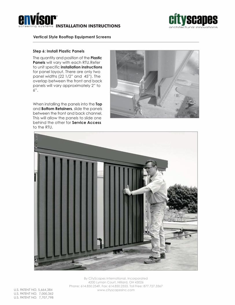
Step 6: Install Plastic PanelsThe quantity and position of the PlasticPanels will vary with each RTU.Referto unit specific installation instructionsfor panel layout. There are only twopanel widths (22 1/2” and 45”). Theoverlap between the front and backpanels will vary approximately 2” to6”.
When installing the panels into the Topand Bottom Retainers, slide the panelsbetween the front and back channel.This will allow the panels to slide onebehind the other for Service Accessto the RTU.
installation instructions 17
U.S. PATENT NO. 5,664,384U.S. PATENT NO. 7,000,362U.S. PATENT NO. 7,707,798

INSTALLATION INSTRUCTIONS
U.S. PATENT NO. 5,664,384
By CityScapes International, Incorporated4200 Lyman Court, Hilliard, OH 43026
Phone: 614.850.2549, Fax: 614.850.2553, Toll Free: 877.727.3367www.cityscapesinc.com
Vertical Style Rooftop Equipment Screens
Step 7: Install End CapsWith all of the Plastic Panels installed, begin at one corner with an End Cap, and positionit flush over the ends of both the T.R. and B.R. Use the 1/1/4” long stainless steel TEK screwsto attach the End Caps to the Retainer extrusions at top and bottom.
installation instructions 18
U.S. PATENT NO. 5,664,384U.S. PATENT NO. 7,000,362U.S. PATENT NO. 7,707,798

INSTALLATION INSTRUCTIONS
U.S. PATENT NO. 5,664,384
By CityScapes International, Incorporated4200 Lyman Court, Hilliard, OH 43026
Phone: 614.850.2549, Fax: 614.850.2553, Toll Free: 877.727.3367www.cityscapesinc.com
Vertical Style Rooftop Equipment Screens
Step 8: Final Details
If you have any questions about the installation of the Envisor systemwe encourage you to call us at 1 877 727 3367
Installing the End Caps completes the last component assembly step.
Next, locate the blue and white label in your hardware carton that says “NOTICE” at thetop. This label should be placed on the outside surface of the panel that has the RTU’sDisconnect Switch located behind it. Remove the backing from the label and apply it tothis panel so that it is plain view.
Also inside the hardware carton you will find small white plastic bottles of “touch up” paintin the same color as your Envisor Screen. This paint should be used to touch up any smallpanel scratches or screw heads that may have had the painted surface damaged duringinstallation.
Finally we recommend walking around the entire RTU’s screen to inspect and make anyadjustments in the position of the panels. Sliding plastic panels left or right for even spacingwill complete your installation.
installation instructions 19
U.S. PATENT NO. 5,664,384U.S. PATENT NO. 7,000,362U.S. PATENT NO. 7,707,798