Embed Size (px)
Citation preview
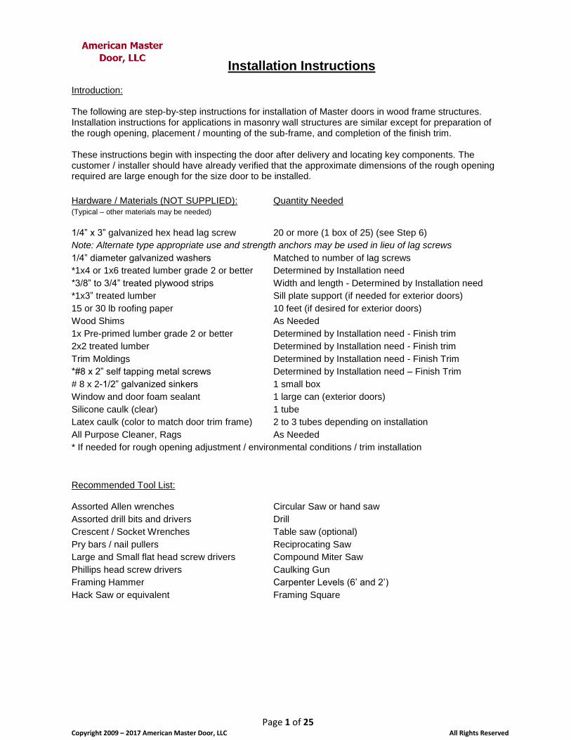
Installation Instructions
Page 1 of 25 Copyright 2009 – 2017 American Master Door, LLC All Rights Reserved
Introduction: The following are step-by-step instructions for installation of Master doors in wood frame structures. Installation instructions for applications in masonry wall structures are similar except for preparation of the rough opening, placement / mounting of the sub-frame, and completion of the finish trim. These instructions begin with inspecting the door after delivery and locating key components. The customer / installer should have already verified that the approximate dimensions of the rough opening required are large enough for the size door to be installed.
Hardware / Materials (NOT SUPPLIED): Quantity Needed (Typical – other materials may be needed)
1/4” x 3” galvanized hex head lag screw 20 or more (1 box of 25) (see Step 6)
Note: Alternate type appropriate use and strength anchors may be used in lieu of lag screws
1/4” diameter galvanized washers Matched to number of lag screws
*1x4 or 1x6 treated lumber grade 2 or better Determined by Installation need
*3/8” to 3/4” treated plywood strips Width and length - Determined by Installation need
*1x3” treated lumber Sill plate support (if needed for exterior doors)
15 or 30 lb roofing paper 10 feet (if desired for exterior doors)
Wood Shims As Needed
1x Pre-primed lumber grade 2 or better Determined by Installation need - Finish trim
2x2 treated lumber Determined by Installation need - Finish trim
Trim Moldings Determined by Installation need - Finish Trim
*#8 x 2” self tapping metal screws Determined by Installation need – Finish Trim
# 8 x 2-1/2” galvanized sinkers 1 small box
Window and door foam sealant 1 large can (exterior doors)
Silicone caulk (clear) 1 tube
Latex caulk (color to match door trim frame) 2 to 3 tubes depending on installation
All Purpose Cleaner, Rags As Needed
* If needed for rough opening adjustment / environmental conditions / trim installation
Recommended Tool List: Assorted Allen wrenches Circular Saw or hand saw
Assorted drill bits and drivers Drill
Crescent / Socket Wrenches Table saw (optional)
Pry bars / nail pullers Reciprocating Saw
Large and Small flat head screw drivers Compound Miter Saw
Phillips head screw drivers Caulking Gun
Framing Hammer Carpenter Levels (6’ and 2’)
Hack Saw or equivalent Framing Square

Installation Instructions
Page 2 of 25 Copyright 2009 – 2017 American Master Door, LLC All Rights Reserved
Step 1: Unpacking and Part Inventory
Your door(s) were either delivered on a pallet with a protective frame and cover, or within a wooden crate. Remove the necessary protection material or crate top to expose the door(s).
Pallet Delivery Configuration
Note our shipping configuration has been upgraded, but the content will be the same. Locate the sub-frame components (photo center), decorative sill plate cover (lower right) and Master Hardware Box (upper left). Remove these components from the packing and set aside.
Open the boxing that contains the door and Finish frame (single doors only). Double doors will have the Finish frame in 3 separate pieces.
Carefully (with assistance - door is HEAVY) lift one end of the door / frame and verify:
Desired door style, panel style (both door sides), color, and finish frame color.
Verify five (5) pieces for the sub-frame (2 side and 1 top member, 2 stabilizer bars. 1 pouch of 4 screws)
Verify one (1) piece for decorative sill plate cover
Open the hardware box and verify:
Handle Hardware Box (style and finish color) (see photo below)
o Handles (2 per door), Locking Knob (1 per door), Flange cover plates (3 per door), Set screws (4) – 2 pointed, 2 flat end, Allen Wrench (small), handle connection arm (2 pieces), handle flange mounting screws (8)
o Finish Frame connector clips and bolts (8)
o Finish frame plugs (Five (5) for single door, Ten (10) for Double / French door)
o Plug color matches frame color
o Bag with lock cylinder, three (3) keys, key code card
o Spy Eye (peep hole) box (if requested)

Installation Instructions
Page 3 of 25 Copyright 2009 – 2017 American Master Door, LLC All Rights Reserved
Hardware Box Contents
Contact American Master Door at (919) 345-8708, as soon as possible to report any discrepancies.
Step 2: Rough Opening Preparation
This step is not required if installation is being performed in new construction. Remove existing interior and exterior trim molding. If planning to reuse this trim, use care not to damage or break the molding. Remove the door from the hinges. Starting at the lowest hinge, use a small screwdriver and hammer to tap on the bottom of the each hinge pin and drive it through the top. Repeat for all hinges. The door can now be removed from the hinges. Unless the door jamb is to be salvaged, use a reciprocating saw and cut the door jamb in half to facilitate removal. Otherwise, use the reciprocating saw, with an all-purpose cutting blade, to cut the nails between the wall framing studs and the door jamb. Remove the door jamb, any nails or partially cut nails, shims, or other leftover materials from both the edges and face sides of the wood studs. At this point, the original door opening frame should be completely exposed and free of interferences.
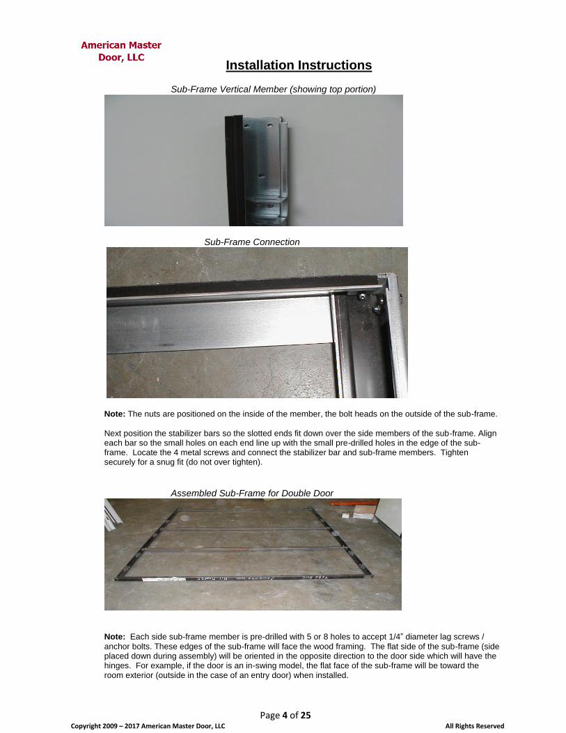
Step 3: Assemble Sub-frame
If the sub-frame is pre-assembled, this step can be skipped. Locate the five pieces for the sub-frame and the small plastic bag (located in the Master handle set hardware box) containing 4 small hex head bolts and nuts and 4 - 1” metal screws. There will be two (2) sub-frame side (vertical) members, one (1) top (horizontal) member and two (2) stabilizer bars. Layout the sub-frame members on a horizontal surface with the flat face down (smooth – has no holes or rivets). Position the side members so their ends that have 2 side-by-side pre-drilled holes are oriented toward the top member. Connect the sub-frame members together with the bolts and nuts provided and loosely hand tighten at this point.
Installation Instructions
Page 4 of 25 Copyright 2009 – 2017 American Master Door, LLC All Rights Reserved
Sub-Frame Vertical Member (showing top portion)
Sub-Frame Connection
Note: The nuts are positioned on the inside of the member, the bolt heads on the outside of the sub-frame.
Next position the stabilizer bars so the slotted ends fit down over the side members of the sub-frame. Align each bar so the small holes on each end line up with the small pre-drilled holes in the edge of the sub-frame. Locate the 4 metal screws and connect the stabilizer bar and sub-frame members. Tighten securely for a snug fit (do not over tighten).
Assembled Sub-Frame for Double Door
Note: Each side sub-frame member is pre-drilled with 5 or 8 holes to accept 1/4” diameter lag screws /
anchor bolts. These edges of the sub-frame will face the wood framing. The flat side of the sub-frame (side placed down during assembly) will be oriented in the opposite direction to the door side which will have the hinges. For example, if the door is an in-swing model, the flat face of the sub-frame will be toward the room exterior (outside in the case of an entry door) when installed.
Installation Instructions
Page 5 of 25 Copyright 2009 – 2017 American Master Door, LLC All Rights Reserved
Step 4: Verification of Rough Opening Dimensions and Plumb
Using a measuring tape, measure and record the inside distance between the door framing studs at the top middle and bottom of the opening. Now measure and record the distance from the floor to the bottom of the door header in both corners. Using at least a 2-foot level (preferably 4-foot or 6-foot), place the edge of the level on either side edge of the wood studs (interior or exterior wall sides) that form the face of the rough opening, to determine if the framing is plumb or how much it is out of plumb. If the door framing is seriously out of plumb, and can be corrected, it should be done now. Otherwise, simply keep the result in mind and note that the degree that the wall is out of plumb will affect the effort required to perform the final trim work. So now determine the smallest of these three distances, is larger than width of the sub-frame rough openings The Master Security door sub-frame includes stabilizer bars to keep the sub-frame square while being installed. Frequently, the wall stud framing is not perfectly square or plumb. Most often very little can be done to correct original framing issues, so the key to a smooth installation will require that the sub-frame be installed plumb.
Step 5: Rough Opening Adjustments (if required)
This step is required if the rough opening is not large enough to accommodate the width and/or height of
the sub-frame. Generally speaking, when the Master Door is installed in consistently humid locations (i.e.
Florida and other Deep South coastal locations), pressure-treated lumber should be used as the facing
boards within the rough opening. This can be accomplished by cutting out and replacing the existing 2x4
(or 2x6) jack studs on either side of the rough opening, with pressure-treated material. In other locations
where frequent high relative humidity is not an issue, generally the caulking and shims will provide
adequate isolation between the framing wood in the sub-frame metal. If additional isolation is desired,
consider applying a single strip of 15 or 30 pound roofing felt paper or one layer of thin flexible foam sill
insulation, on the wood stud surfaces prior to installing the sub-frame (See step 6). Bear in mind that you
will probably need to add wood shims above and below each of the anchors when finally setting the sub-
frame. If this extra step is taken, ensure the shims are placed under this material to minimize tearing.
Since the Master door sub-frame is typically wider than normal door jambs, it is common to perform some
modification to the rough opening in order to accommodate the sub-frame installation. Depending on the
amount of enlargement required, various techniques can be used. It is the customer / installers discretion
as to the best process for the circumstances. When the rough opening is just a little too tight for the sub-
frame to fit easily, the rough opening jack studs may be slightly channeled or grooved to provide clearance
for the sub-frame assembly bolt heads.
Generally, one (possibly both) jack stud is removed and replaced with a treated 1x4 (or 1x6). If one or both
jack studs are replaced, treated plywood strips of desired thickness can be cut to match the 2x4 (or 2x6)
stud size in order to shrink the overall rough opening to a size that more closely accommodates the sub-
frame width. Install any additional materials along the door header to minimize that open space. Be sure to
verify the proper height needed for sub-frame clearance above the finished floor.
Install the replacement material with appropriate size nails and adhesives, taking care to avoid nailing in the areas where the sub-frame anchor bolts (lag screws) will be installed.
Step 6: Sub-Frame Installation Layout In-swing Doors – Prep for sub-frame anchors: If the wall / door opening framing are not plumb, measure from the (room side) jack stud edge (near the top of the door opening) horizontally toward the exterior, a distance of 1-3/8”. Mark this point and then repeat

Installation Instructions
Page 6 of 25 Copyright 2009 – 2017 American Master Door, LLC All Rights Reserved
the measurement process near the floor, and on the other side of the door opening. Now place and keep the top of a 6 foot level aligned with top mark only and adjust the lower part of the level until it shows plumb. If there is less than 1-3/8” from the level edge to the interior stud edge, move the level to line up with the lower mark made near the floor. Adjust the position of the level till it shows plumb, then use the level as a straight edge and draw a line along the length. This will be the center line for the bolt holes on the sub-frame. Extend the line along the full length of the stud and repeat the process on the opposite side stud. Note: The use of 1-3/8” will make the inside finish trim molding line up evenly with the finish trim of the
door. This distance assumes a 1/2” sheet rock wall thickness attached directly to the stud framing. If 5/8” sheet rock is being used, make your bolt hole center line at 1-5/16”. Your interior finish trim molding will still line up well and provide adequate wood support for the bolts. If any other material is installed between the wall framing and the sheet rock, make the bolt hole center line at 1-5/8”. This situation would be very similar to installing an Out-swing door due to the extra materials applied to the exterior of the home or building. In this situation, you’ll need to add trim board to the face of the jack studs on the interior room side of the framing. Your finish trim molding will then match up with this trim board.
Out-swing Doors – Prep for sub-frame anchors: Review the above process for in-swing doors. Generally, placement of an out-swing door in exterior wall openings is a matter of personal preference due to the exterior surface material and thickness. The important consideration is to ensure a minimum of 1-5/16” wood thickness to support the sub-frame anchors. In this case, more is better and the anchor bolt center line is generally made plumb, centered in the width of the jack stud. NOTE: If the door is to be used in an interior location and the wall construction is wood framing, the sub-
frame can be installed per the “In-swing” instructions above. This will allow the trim molding on the outside surround of the door to be easily installed and the interior side trim will require the most effort. In exterior wall installations, Out-swing doors, may require pieces of trim board to be installed on the jack stud faces for both the inside and outside of the door.
Step 7: Sub-Frame Installation
Note: The most critical part of the installation process is the sub-frame installation. Invest extra care to
install the sub-frame as plumb as possible, and by not distorting from square / twisting, or over torquing the anchors. The adjustable hinges and finish frame will be able to compensate for some sub-frame positioning issues. Note: For an inward swinging door, orient the sub-frame so that its smooth, wide face side is oriented
toward the exterior side of room or building. Note: If additional anchors are desired to those holes that have been pre-drilled, additional anchor holes
can be drilled in the sub-frame at this time.
Mark position of sub-frame mounting holes:
Once the sub-frame bolt hole center line is established, place the sub-frame within the door rough opening. Lift and support the frame for proper height off the finished floor on both sides. Ensure the top inside corners of the sub-frame are at 90 degrees (square). Then position the bolt holes of the sub-frame so that the bolting center line runs through the center of each bolt hole. Now mark the middle of each bolt hole on the center line. Repeat for other side of the sub-frame and the top member.
Drill pilot holes for mounting bolts / lag screws: The sub-frame holes are sized to accept up to a 5/16” diameter lag screw. Generally, 1/4” diameter lag screws or alternate anchors are used. If 5/16” hardware is used, be sure to test that the bolt /lag screw will smoothly and completely fit through the sub-frame holes. After the sub-frame mounting holes are marked

Installation Instructions
Page 7 of 25 Copyright 2009 – 2017 American Master Door, LLC All Rights Reserved
on the wood framing jack studs and header, drill pilot holes for each anchor. Use a 3/16” bit (or installer option) and drill to a depth of 2 to 2-1/2”. Drill the pilot holes as straight and level as possible.
Installation: If the sub-frame will not be overly tight when placed in the rough opening, 1 or 2 beads of clear silicone caulk can be run vertically on the jack studs in the area that will be beneath the sub-frame. Alternately, the installer may wish to install a strip of roofing paper or sill insulation on the face of the rough opening studs at this time. Punch small holes in this material to show where the pilot holes have been made. Place the sub-frame in the rough opening. If the sub-frame has space on either side of the rough opening studs, orient the frame so that most shims will be used in the rough opening on the side opposite from the door hinges. Align the sub-frame with the pilot holes and install shims above and below (side to side for the top) where the anchors will be placed. Then begin partially installing the anchors (with washers) starting at the top on each side and alternately moving to each side while working toward the bottom. Check for plumb frequently and make adjustments as needed. The (top) header anchors can be installed last.
Shims Installed Around Sub-Frame Anchors
After all the anchors are partially installed, recheck for plumb and then install each anchor completely. Monitor that the final tightening process does not cause the sub-frame to move from plumb. Tighten anchors till they are fully seated (snug but not torqued) and then tighten an additional 1/4 turn or less. They do not need to be torqued. Once the sub-frame anchors are installed verify plumb is adequate, then remove the stabilizer bars and discard (recycle to Category 5 if desired). Install non-expanding door & window foam insulation to fill any openings between the sub-frame and the rough opening studs. Clean excess insulation when dry, trim excess shim material (cut shims even with the edges of the sub-frame) and then use latex or silicone caulk to completely seal the exterior joint between the sub-frame and the stud.
Step 8: Installing the Finish Frame
With the sub-frame installed, installing the door will require two (2) persons due to the weight and general bulk. The Finish Frame installation is the last step prior to hanging the door. This frame provides the trim profile around the main door unit and includes the lower portion of the two (2) piece hinge assembly.

Installation Instructions
Page 8 of 25 Copyright 2009 – 2017 American Master Door, LLC All Rights Reserved
Single Door Units - Disengaging Finish Frame from Door Unit: If you are installing a Single door, the Finish frame is generally installed around the door unit when shipped. The Finish frame may be secured to the door with the locking bolts engaged. If you are installing a Double or French door, review instructions further below for assembling the Finish Frame. If assembled together, stand the combined door and frame upright against a secure support. Locate the plastic bag (in the Master Handle Hardware box) containing the lock cylinder and keys. Remove the cylinder and keys. Test to ensure the keys and cylinder work properly.
Lock Cylinder
Loosen the cylinder release screw located below the locking pins on the edge of the door (see photo). Do not remove this screw, but loosen enough in order to grasp the screw head. Grasp the screw head and pullout, then release. You will see that it has a spring tension associated with it. Looking through the key cylinder hole, you can see the small pin that is operated by this screw. This pin fits into the hole in the cylinder (see photo above)
Cylinder Release Screw Located Below Locking Pin
If the door already has the lock face plate installed and secured (see photos of components below, insert the lock cylinder (end with the key slot) into the lock hole from the interior side of the door. The cylinder must be fully inserted through the hole and into the lock face plate. Note: The lock cylinder has a black tab that will rotate. It can be manually rotated or will operate when the
key is turned. Make sure this tab is not protruding out from the side of the cylinder when trying to insert in the lock hole. If there are lock cylinder sleeves to buildout the lock opening, a screw driver may be needed to align the sleeves to ease insertion of the cylinder. In addition, you may need to release and pull out on the cylinder locking screw (as described above) to help ease the cylinder into the hole, and you may need to gently tap the cylinder into place with a hammer.

Installation Instructions
Page 9 of 25 Copyright 2009 – 2017 American Master Door, LLC All Rights Reserved
Lock Cylinder Completely Inserted From Interior Room Side
Note: The above photo shows lock activation arm cut to length to suit overall door panel configuration and
attachment of locking knob.
Ensure lock cylinder is completely inserted. When the cylinder is properly inserted, the key will move and be able to turn and retract the locking bolts. If the key will move the lock bolts, tighten the cylinder lock adjustment screw. Fully retract the locking bolts. After the locking bolts are retracted, carefully remove the door unit from the Finish Frame. You may have to lift the bottom door corners a little to extract the finish frame.
Assembling the Finish Frame (Typically - Double and French Doors): Locate the three (3) pieces that comprise the Finish frame side and top members. Locate the sill plate. Lay out the frame members face down on a smooth surface that will not damage the frame finish. The connector piece will slide into the channel for both frame members. Remove the two (2) Allen head screws (1/2” long) that are threaded into sides of each connector (may be found separately in the hardware box).
Finish Frame Top and Side Connector with Screws
Loosen the Allen head screw in the frame connector tightening clamp and slide the connector into the channels of the top and side frame members. Move both members together to form a 90 degree angle with the corners aligned snug and even. Align screw holes in the connector with those in the Finish frame and insert Allen head screws. Tighten screws securely while maintaining position of frame members. Securely tighten connector clamp screw.

Installation Instructions
Page 10 of 25 Copyright 2009 – 2017 American Master Door, LLC All Rights Reserved
Finish Frame Members Properly Aligned
Installation of sub-Sill Trim Noser:
The addition of a sub-sill trim plate (noser) serves as base protection over the doorway sub-floor, and as the finish plate located under the door sill plate. If a sub-sill noser was included with the door, the best time to install this item is during, and just prior to installing the sub-frame. The noser may or may not be desired for installation on a concrete floor. Cut the sub-sill noser to fit the width of the rough opening. If the sub-frame has already been installed, notch out both ends of the noser to enable placement that is even with the inside edge of the sub-frame. Note: The noser has a 1-1/2” deep face that can be cut with a table saw (metal cutting blade) to the desired face depth. Align noser so that it lines up with the planned inside edge of sub-frame. Identify and mark a location on the noser to install mounting screws. Drill pilot holes for the screws (recommend 1-1/2” deck screws). Countersink, if desired, around the pilot holes (minimize depth of countersink area) so the screws install nearly flush with the rest of the noser. Use care not to over indent the noser when installing the screws. See following photos.
Positioning the Sub-Sill Nosing

Installation Instructions
Page 11 of 25 Copyright 2009 – 2017 American Master Door, LLC All Rights Reserved
Securing the Nosing Trim
Finished Installation of Sill Nosing
Attaching / Removing the Sill Plate: Removing Sill Plate: Single doors will typically be provided with the sill plate already installed / connected to the Finish frame. The sill plate can be removed for use in interior room locations. Before installing the finish frame on the sub-frame, position the frame with the wide flat face facing down on a protected surface to keep from scratching or causing an abrasion to the frame’s finish. Remove the screw on each side that connects the sill plate to the frame.

Installation Instructions
Page 12 of 25 Copyright 2009 – 2017 American Master Door, LLC All Rights Reserved
Sill Plate Connection Screw and Mounting Bracket
Remove the support bracket and move the frame side member outward to remove the sill plate tab from the slot. Repeat from the other end of the sill plate.
Sill Plate Tab Inserted in Slot on Finish Frame
Attaching Sill Plate: If the sill plate is provided separately, (i.e. Double and French doors), and the door is to be used for an exterior entryway application, the sill must be attached. If the door is to be used in an interior location and the sill is not needed, the steps related to the sill plate and support board are not applicable. With the finish frame positioned flat and protected from damage, attach the sill plate by sliding it into place from the bottom. Carefully move the frame side members outward and insert the sill plate tab and mounting
clip into the slots near the bottom of each member (see photo above). Secure with 1/2” # 6 pointed head metal screw.
Sill Plate Mounting Clip
Installation Instructions
Page 13 of 25 Copyright 2009 – 2017 American Master Door, LLC All Rights Reserved
Sill Plate Connection Screw and Mounting Bracket
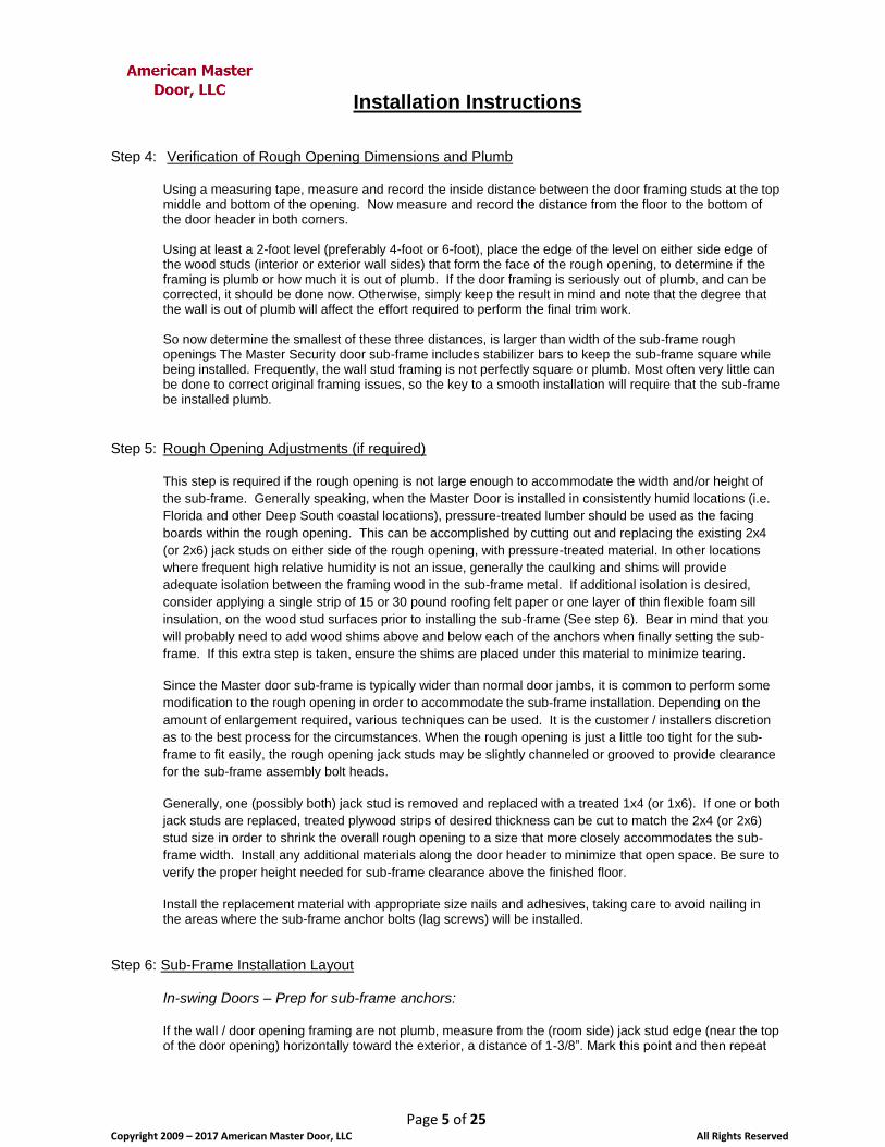
Install a piece of treated 1x3” or PVC board beneath where the recessed section of the sill plate will fit when installed (see photos – coming). This board will provide support for the sill plate. To ensure proper placement of the 1x3”, first cut the board to fit. Measure the width of metal sill plate recessed space and cut the board to easily fit in the recess under the sill plate (cut the board roughly 1/8” narrower than the space under the sill plate). Dry fit the board in the underside recess of the sill plate. Ensure the sill plate is attached to the finish frame, then temporarily install the finish frame to the sub-frame (see instructions below). (If desired, include the 1x3” piece beneath the sill plate to confirm fit and location). Mark the width and ends of the sill plate on the sub-sill or flashing / concrete. Then remove the finish frame with attached sill plate (and 1x3” piece). Place the 1x3” in the space where the sill plate will cover this support board (between the marks made for the width and ends of the sill plate). Ensure the ends of the 1x3” are positioned for the sill plate to be placed over top of this board. Mark the final position for installation. Caulk the bottom of the 1x3” board and the area of flashing or sub-sill nosing where the 1x3” will be installed. Position 1x3” board and attach to the subfloor or concrete floor through the sub-sill plate or flashing. Countersink holes in the 1x3” to accommodate the screw heads, if used. If concrete fasteners are used, ensure the heads are flush with the support board. Use three (3) to four (4) fasteners of Installer’s desired type, length and size. Finish Frame Attachment to Sub-Frame: Locate the 8 Finish frame connector clips and 8 black connector bolts in the Hardware box. Install the Finish frame mounting clips in the slots on the sub-frame. Orient the angled part of the clip toward the wall. A small piece of tape (not required, but may ease aligning the bolts with the clips) may be added to the clip to keep it from dropping completely into the slot.
Installation of Finish Frame Connector Clips (Front view)
Installation Instructions
Page 14 of 25 Copyright 2009 – 2017 American Master Door, LLC All Rights Reserved
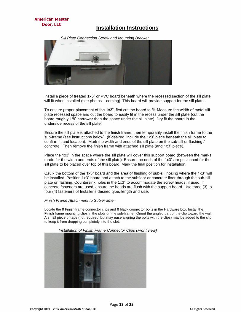
Insert all the connector clips, then set the finish frame over the sub-frame. Ensure when the finish frame is ready to be bolted, that it is properly aligned so the sill plate, if used, sits properly over the installed 1x3” support board. Begin installing the connector bolts. You may need to probe slightly with the bolt to capture and engage the connector clip hole. Then hand-tighten until nearly seated. Install all connector bolts in this manner. Verify plumb for the finish frame. Some minor adjustments can be made here with the connector bolts. Finally, tighten the connector bolts (avoid over torqueing) in an alternating pattern, side to side and top to bottom.
Finish Frame Connector Bolt
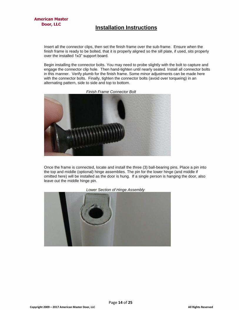
Once the frame is connected, locate and install the three (3) ball-bearing pins. Place a pin into the top and middle (optional) hinge assemblies. The pin for the lower hinge (and middle if omitted here) will be installed as the door is hung. If a single person is hanging the door, also leave out the middle hinge pin.
Lower Section of Hinge Assembly

Installation Instructions
Page 15 of 25 Copyright 2009 – 2017 American Master Door, LLC All Rights Reserved
Lower Section of Hinge Assembly – Pin Inserted
Locate the bag in the handle hardware box that contains 5 (10-for a double door) rectangular, plastic, hole insert plugs. Push these recess plugs into the open rectangular spaces on the hinge side of the frame. These spaces accommodate the hinge side control bolts. When completed, the Finish frame edge should generally be flush with the finished wall on the interior of the room (in-swing door only).
Installed Control Pin Recess Plug
Installation Instructions
Page 16 of 25 Copyright 2009 – 2017 American Master Door, LLC All Rights Reserved
Completed Sill on Top of Nosing
Step 9: Installing the Door
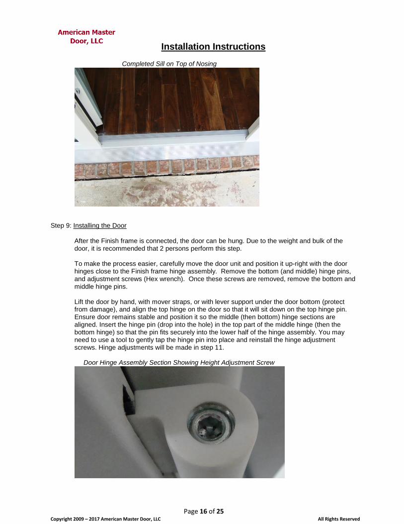
After the Finish frame is connected, the door can be hung. Due to the weight and bulk of the door, it is recommended that 2 persons perform this step. To make the process easier, carefully move the door unit and position it up-right with the door hinges close to the Finish frame hinge assembly. Remove the bottom (and middle) hinge pins, and adjustment screws (Hex wrench). Once these screws are removed, remove the bottom and middle hinge pins. Lift the door by hand, with mover straps, or with lever support under the door bottom (protect from damage), and align the top hinge on the door so that it will sit down on the top hinge pin. Ensure door remains stable and position it so the middle (then bottom) hinge sections are aligned. Insert the hinge pin (drop into the hole) in the top part of the middle hinge (then the bottom hinge) so that the pin fits securely into the lower half of the hinge assembly. You may need to use a tool to gently tap the hinge pin into place and reinstall the hinge adjustment screws. Hinge adjustments will be made in step 11. Door Hinge Assembly Section Showing Height Adjustment Screw

Installation Instructions
Page 17 of 25 Copyright 2009 – 2017 American Master Door, LLC All Rights Reserved
Hinge Adjustment Screw Removed
Hinge Pin Inserted in Top of Hinge Assembly
Step 10: Installing the Lock, Handle Set and Spy Eye (if applicable) Hardware
Installing the Handle Hardware:
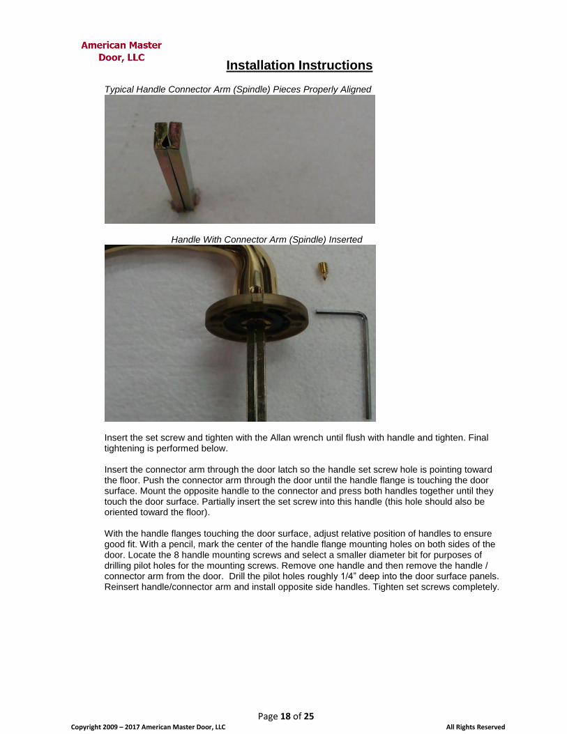
In the Master box containing the handle Hardware set, locate the small plastic bag containing 4 set screws, 1 small Allan wrench and the 2 metal pieces that make up the handle connector arm. Hold the connector arm pieces together so that they form a triangle shape opening as shown in the photo below. Position one of the handles with the set screw hole facing up (see photo). Insert the connector arm in the handle with the open triangle space positioned up. The set screw will penetrate into this space on the connector arm.
Installation Instructions
Page 18 of 25 Copyright 2009 – 2017 American Master Door, LLC All Rights Reserved
Typical Handle Connector Arm (Spindle) Pieces Properly Aligned
Handle With Connector Arm (Spindle) Inserted
Insert the set screw and tighten with the Allan wrench until flush with handle and tighten. Final tightening is performed below. Insert the connector arm through the door latch so the handle set screw hole is pointing toward the floor. Push the connector arm through the door until the handle flange is touching the door surface. Mount the opposite handle to the connector and press both handles together until they touch the door surface. Partially insert the set screw into this handle (this hole should also be oriented toward the floor). With the handle flanges touching the door surface, adjust relative position of handles to ensure good fit. With a pencil, mark the center of the handle flange mounting holes on both sides of the door. Locate the 8 handle mounting screws and select a smaller diameter bit for purposes of drilling pilot holes for the mounting screws. Remove one handle and then remove the handle / connector arm from the door. Drill the pilot holes roughly 1/4” deep into the door surface panels. Reinsert handle/connector arm and install opposite side handles. Tighten set screws completely.

Installation Instructions
Page 19 of 25 Copyright 2009 – 2017 American Master Door, LLC All Rights Reserved
Handle Flange Mounting Holes
Installing the Lock Hardware:
The photo below shows an older version of the lock cover plate. Note that the current version of the lock
faceplate (photos pending) includes a protector for the key cylinder, and a trim ring.
This version of the faceplate is installed over the lock cylinder with the slot aligned with the cylinder.
Inside of Lock Cover Plate (Older Version)
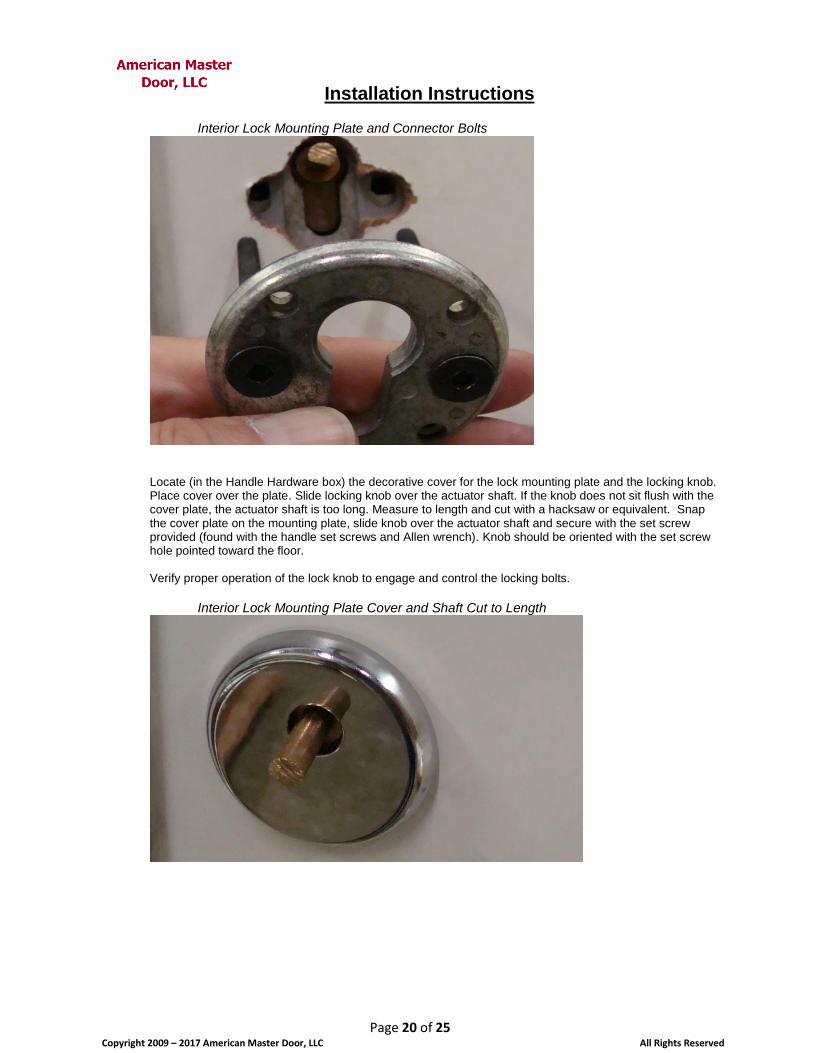
Insert the interior side lock mounting plate and connector bolts through the holes on the interior side of the door and align bolts into the holes in the front cover plate. Tighten securely (avoid over tightening).
Installation Instructions
Page 20 of 25 Copyright 2009 – 2017 American Master Door, LLC All Rights Reserved
Interior Lock Mounting Plate and Connector Bolts
Locate (in the Handle Hardware box) the decorative cover for the lock mounting plate and the locking knob. Place cover over the plate. Slide locking knob over the actuator shaft. If the knob does not sit flush with the cover plate, the actuator shaft is too long. Measure to length and cut with a hacksaw or equivalent. Snap the cover plate on the mounting plate, slide knob over the actuator shaft and secure with the set screw provided (found with the handle set screws and Allen wrench). Knob should be oriented with the set screw hole pointed toward the floor. Verify proper operation of the lock knob to engage and control the locking bolts.
Interior Lock Mounting Plate Cover and Shaft Cut to Length
Installation Instructions
Page 21 of 25 Copyright 2009 – 2017 American Master Door, LLC All Rights Reserved
Locking Knob Installed on Actuator Shaft
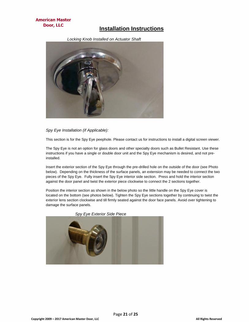
Spy Eye Installation (if Applicable):
This section is for the Spy Eye peephole. Please contact us for instructions to install a digital screen viewer.
The Spy Eye is not an option for glass doors and other specialty doors such as Bullet Resistant. Use these
instructions if you have a single or double door unit and the Spy Eye mechanism is desired, and not pre-
installed.
Insert the exterior section of the Spy Eye through the pre-drilled hole on the outside of the door (see Photo
below). Depending on the thickness of the surface panels, an extension may be needed to connect the two
pieces of the Spy Eye. Fully insert the Spy Eye interior side section. Press and hold the interior section
against the door panel and twist the exterior piece clockwise to connect the 2 sections together.
Position the interior section as shown in the below photo so the little handle on the Spy Eye cover is
located on the bottom (see photos below). Tighten the Spy Eye sections together by continuing to twist the
exterior lens section clockwise and till firmly seated against the door face panels. Avoid over tightening to
damage the surface panels.
Spy Eye Exterior Side Piece

Installation Instructions
Page 22 of 25 Copyright 2009 – 2017 American Master Door, LLC All Rights Reserved
Spy Eye Interior Side Piece
Spy Eye Interior Side – Proper Alignment
Step 11: Hinge Adjustments
The Master door can be adjusted in height up or down, and laterally side to side with the adjustable hinge system. Each hinge is adjusted when a height correction is needed. Typically either 2 or 3 hinges are adjusted to correct for plumb and latching issues.
Height Adjustments: The door height corrections are made using the hinge adjustment screw shown below. Typically when the door is first hung, one of the hinges will be supporting more of the door weight than the others. Using an appropriate size Allen wrench, test each hinge by turning the adjustment screw clockwise. The clockwise motion will attempt to raise the door height. One adjustment screw may appear harder to turn than the others and will indicate the hinge that corrections should start with. If the door is at the correct height, turn the adjustment screws of the other hinges clockwise until apparently equal turning resistant is felt. If the door height is too high, begin with the tightest adjustment screw and turn it counter-clockwise until it turns easily. Move to next tightest screw and repeat the process. Repeat the entire sequence for all screws until the desired height is reached. Then tighten all screws to an equal resistance.

Installation Instructions
Page 23 of 25 Copyright 2009 – 2017 American Master Door, LLC All Rights Reserved
Hinge Height Adjustment Screw
Lateral Hinge Adjustments: Lateral adjustments are made to correct minor plumb issues or to change the clearance at the door latch. Remove the lower hinge covers (slide down) to expose the hinge mounting bolts.
Hinge Cover Partially Removed to Expose Mounting Bolts
There are 2 mounting bolts for each hinge. To move the door left or right, loosen 5 of the 6 total bolts, leaving either the very top or bottom bolt tight. Caution: Consider inserting a tapered wedge to restrict movement of the door until the bolts are loosened
and you are ready to control the desired movement. Move the door left or right the desired distance and retighten the very top or bottom hinge bolts that were loosened, leaving the center hinge bolts loose. Now loosen the remaining hinge single remaining (top or bottom) bolt that was not loosened. Plumb the door, secure from moving by tightening 1 of the remaining loose bolts. Tighten all remaining bolts and verify all hinge bolts are securely tight.
Adjust Latch Striker Plate: If the door does not latch properly or you can shake the door and get movement around the latch (with door unlocked), then the latch strike plate needs to be adjusted.

Installation Instructions
Page 24 of 25 Copyright 2009 – 2017 American Master Door, LLC All Rights Reserved
Locate the latch adjustment plate release screw on the Finish frame next to the latch and locking bolt holes. Use an Allen wrench to loosen this screw. Turn counter-clockwise to loosen the plate.
Latch adjustment plate release screw
The main door latch adjustment plate is located in the Finish frame space opposite the door latch. Notice that the latch plate is tapered around the circumference. When the adjustment screw is loosened, turn the plate with your fingers to the desired thickness. Retighten the adjustment screw and test the latching process. Repeat as needed to obtain a secure, tight and consistent latch when the door is closed.
Adjustable Latching Plate
Note: If you are installing a Double or French door, or a single door with a top edge locking bolt, there are
additional top bolt latching devices that may need adjustment. The adjustment process for those devices follows is the same as above.
Step 12: Finish Trim
Your door is now operable and ready to trim out. Please contact us if you have questions, or would like suggestions or guidance regarding the trim out process. Typically, an inward swing door will have the finish frame aligned flush with the interior finished wall. The interior trim molding can then be installed against the edge of the finish frame. The exterior side of the door is where the jamb is manually constructed. PVC trim material is a recommended material to build the jamb, if the right conditions apply. If the door is an outward swing, then the trim requirements are based on actual positioning of the door. Self-tapping metal screws (2 inch or less) can be used to attach the base (hidden) jamb material to the door sub-frame (if needed). We recommend use of select treated lumber for the base jamb material, and smooth or wood grain PVC boards on the exposed surface areas of the door jamb. We also recommend

Installation Instructions
Page 25 of 25 Copyright 2009 – 2017 American Master Door, LLC All Rights Reserved
replacing the original exterior side door trim molding with PVC molding that matches the original trim (i.e. Brick mold, or other design).
Completed Installation of Sill Plate and Nosing
Step 13: Cleanup
Remove the clear protective plastic film from the door panels, if applied, and the white protective film from the decorative sill cover, if applied. Clean non-wood door panels, Finish frame and plastic hinge covers with a non-abrasive, non-corrosive type purpose cleaner using a clean soft rag or paper towels. Wood panels may be cleaned with a non-abrasive, non-residue wood cleaner and soft cloth. Remove and dispose of all excess / non-salvaged materials and scrap components. Perform final cleaning of the interior and exterior work space.