Embed Size (px)
Citation preview

440 01 2024 04 Dec. 2010Specifications are subject to change without notice.
INSTALLATION INSTRUCTIONS90+ Two−Stage & Two−Stage, Variable
Category IV, Gas FurnaceC9MVX, H9MVX, T9MVX, C9MPV, H9MPV,
T9MPV, C9MPT, H9MPT, T9MPT(Upflow/Downflow/Horizontal)
These instructions must be read and understood completely before attempting installation.
Safety Labeling and Signal WordsDANGER, WARNING, CAUTION, and NOTEThe signal words DANGER, WARNING,CAUTION, and NOTE are used to identify levels ofhazard seriousness. The signal word DANGER isonly used on product labels to signify an immediatehazard. The signal words WARNING, CAUTION,and NOTE will be used on product labels andthroughout this manual and other manual that mayapply to the product.
DANGER − Immediate hazards which will result insevere personal injury or death.
WARNING − Hazards or unsafe practices whichcould result in severe personal injury or death.
CAUTION − Hazards or unsafe practices whichmay result in minor personal injury or product orproperty damage.
NOTE − Used to highlight suggestions which willresult in enhanced installation, reliability, oroperation.
! WARNING
Signal Words in Manuals
The signal word CAUTION is used throughoutthis manual in the following manner:
! CAUTIONSignal Words on Product LabelingSignal words are used in combination withcolors and/or pictures or product labels.
The signal word WARNING is used throughoutthis manual in the following manner:
Safety−alert symbolWhen you see this symbol on the unit and ininstructions or manuals, be alert to thepotential for personal injury.
TABLE OF CONTENTSStart-up Check Sheets 3. . . . . . . . . . . . . . . . . . . . . . . . . . . . . . . . .Safety considerations 5. . . . . . . . . . . . . . . . . . . . . . . . . . . . . . . . . . .Safe Installation Requirements 5. . . . . . . . . . . . . . . . . . . . . . . . . . . . .Installation 7. . . . . . . . . . . . . . . . . . . . . . . . . . . . . . . . . . . . . . . . . . .Combustion & Ventilation Air 11. . . . . . . . . . . . . . . . . . . . . . . . . . . . . .Vent and Combustion Air Piping 15. . . . . . . . . . . . . . . . . . . . . . . . . . . .Concentric Vent Termination 32. . . . . . . . . . . . . . . . . . . . . . . . . . . . . . .Gas Supply and Piping 33. . . . . . . . . . . . . . . . . . . . . . . . . . . . . . . . . .Electrical Wiring 37. . . . . . . . . . . . . . . . . . . . . . . . . . . . . . . . . . . . . . .Ductwork and Filter 39. . . . . . . . . . . . . . . . . . . . . . . . . . . . . . . . . . . . .Checks and Adjustments 43. . . . . . . . . . . . . . . . . . . . . . . . . . . . . . . . .Furnace Maintenance 46. . . . . . . . . . . . . . . . . . . . . . . . . . . . . . . . . . .Sequence of Operation & Diagnostics (*9MPT) 47. . . . . . . . . . . . . . . . .Wiring Diagram *9MPT (Two-Stage Heating with PSC Motor) 49. . . . . . .Sequence of Operation & Diagnostics (*9MPV, *9MVX) 50. . . . . . . . . . .Wiring Diagram *9MPV, *9MVX (Variable Speed Blower Motor) 52. . . . . .Thermostat Wiring Guide 53. . . . . . . . . . . . . . . . . . . . . . . . . . . . . . . . .
Use of the AHRI Certified TM Mark indicates amanufacturer’s participation in the program.For verification of certification for individualproducts, go to www.ahridirectory.org .
International Comfort Products, LLCLewisburg, TN 37091 U.S.A.
www.icpusa.com
! WARNINGPERSONAL INJURY, AND/OR PROPERTYDAMAGE HAZARDFailure to carefully read and follow this warning couldresult in equipment malfunction, property damage,personal injury and/or death.Installation or repairs made by unqualified persons couldresult in equipment malfunction, property damage,personal injury and/or death.The information contained in this manual is intended foruse by a qualified service technician familiar with safetyprocedures and equipped with proper tools and testinstruments.Installation must conform with local building codes andwith the Natural Fuel Gas Code (NFCG) NFPA 54/ANSIZ223.1, and National standards of CanadaCAN/CSA−B149.1 and .2 Natural Gas and PropaneInstallation Codes.
INSTALLER: Affix these instructions on or adjacent to thefurnace.CONSUMER: Retain these instructions for futurereference.
Portions of the text and tables are reprinted from NFPA 54 /ANSI Z223.1−2009©, with permission of National Fire Protection Association, Quincy, MA 02269 and American Gas Association, Washington, DC20001. This reprinted material is not the complete and official position of the NFPA or ANSI, on the referenced subject, which is represented only by the standard in its entirety.

2 440 01 2024 04Specifications are subject to change without notice.
Required Notice for Massachusetts Installations
ImportantThe Commonwealth of Massachusetts requires compliance with regulation 248 CMR as follows:
5.08: Modifications to NFPA−54, Chapter 10
2) Revise 10.8.3 by adding the following additional requirements:
(a) For all side wall horizontally vented gas fueled equipment installed in every dwelling, building or structure used in whole or in part for residentialpurposes, including those owned or operated by the Commonwealth and where the side wall exhaust vent termination is less than seven (7) feetabove finished grade in the area of the venting, including but not limited to decks and porches, the following requirements shall be satisfied:
1. INSTALLATION OF CARBON MONOXIDE DETECTORS. At the time of installation of the side wall horizontal vented gas fueled equipment, theinstalling plumber or gasfitter shall observe that a hard wired carbon monoxide detector with an alarm and battery back−up is installed on thefloor level where the gas equipment is to be installed. in addition, the installing plumber or gasfitter shall observe that a battery operated or hardwired carbon monoxide detector with an alarm is installed on each additional level of the dwelling, building or structure served by the side wallhorizontal vented gas fueled equipment. It shall be the responsibility of the property owner to secure the services of qualified licenseprofessionals for the installation of hard wired carbon monoxide detectors.
a. In the event that the side wall horizontally vented gas fueled equipment is installed in a crawl space or an attic, the hard wired carbonmonoxide detector with alarm and battery back−up may be installed on the next adjacent floor level.
b. In the event that the requirements of this subdivision can not be met at the time of completion of installation, the owner shall have a periodof thirty (30) days to comply with the above requirement; provided, however, that during said thirty (30) day period, a battery operatedcarbon monoxide detector with an alarm shall be installed.
2. APPROVED CARBON MONOXIDE DETECTORS. Each carbon monoxide detector as required in accordance with the above provisions shallcomply with NFPA 720 and be ANSI/UL 2034 listed and IAS certified.
3. SIGNAGE. A metal or plastic identification plate shall be permanently mounted to the exterior of the building at a minimum height of eight (8)feet above grade directly in line with the exhaust vent terminal for the horizontally vented gas fueled heating appliance or equipment. The signshall read, in print size no less than one−half (1/2) inch in size, “GAS VENT DIRECTLY BELOW. KEEP CLEAR OF ALL OBSTRUCTIONS”.
4. INSPECTION. The state of local gas inspector of the side wall horizontally vented gas fueled equipment shall not approve the installationunless, upon inspection, the inspector observes carbon monoxide detectors and signage installed in accordance with the provisions of 248CMR 5.08(2)(a) 1 through 4.
(b) EXEMPTIONS: The following equipment is exempt from 248 CMR 5.08(2)(a) 1 through 4:
1. The equipment listed in Chapter 10 entitled “Equipment Not Required To Be Vented” in the most current edition of NFPA 54 as adopted by theBoard; and
2. Product Approved side wall horizontally vented gas fueled equipment installed in a room or structure separate from the dwelling, building orstructure used in whole or in part for residential purposes.
(c) MANUFACTURER REQUIREMENTS − GAS EQUIPMENT VENTING SYSTEM PROVIDED. When the manufacturer of Product Approved side wallhorizontally vented gas equipment provides a venting system design or venting system components with the equipment, the instructions provided bythe manufacturer for installation of the equipment and the venting system shall include:
1. Detailed instructions for the installation of the venting system design or the venting system components; and
2. A complete parts list for the venting system design or venting system.
(d) MANUFACTURER REQUIREMENTS − GAS EQUIPMENT VENTING SYSTEM NOT PROVIDED. When the manufacturer of a Product Approvedside wall horizontally vented gas fueled equipment does not provide the parts for venting the flue gases, but identifies “special venting systems”, thefollowing requirements shall be satisfied by the manufacturer:
1. The referenced “special venting system” instructions shall be included with the appliance or equipment installation instructions; and
2. The “special venting systems” shall be Product Approved by the Board, and the instructions for that system shall include a parts list and detailedinstallation instructions.
(e) A copy of all installation instructions for all Product Approved side wall horizontally vented gas fueled equipment, all venting instructions, all parts listsfor venting instructions, and/or all venting design instructions shall remain with the appliance or equipment at the completion of the installation.
For questions regarding these requirements, please contact the Commonwealth of Massachusetts Board of State Examiners of Plumbers and Gas
Fitters, 239 Causeway Street, Boston, MA 02114. 617−727−9952

3Specifications are subject to change without notice.440 01 2024 04
START−UP CHECK SHEETFor PSC Models *9MPT
(This sheet is optional. Keep for future reference.)
Date of Start−Up:
Dealer Name:
Address:
City, State(Province), Zip or Postal Code:
Phone:
Owner Name:
Address:
City, State(Province), Zip or Postal Code:
Model Number:
Serial Number:
Setup Checks
Check the box when task is complete.
All Electrical Connections Tight?
Have hoses been relocated for furnace U/D/H
application?
Condensate Drain Connected?
Condensate Drain Trapped?
Manual Gas Shut−off Upstream of Furnace/Drip Leg
Gas Valve turned ON?
Type of Gas: Natural: Propane: Filter Type and Size:
Shade in Heating Fan “Time OFF” Setting and ThermostatType setting:
Calculated Input (BTU) Rate: (See Checks and
Adjustments Section).
Heating Check
Measured Line Pressure During High Heat:
Measured Manifold Pressure: High Heat
Low Heat
Temperature of Supply Air: High Heat
Low Heat
Temperature of Return Air:
Temperature Rise (Supply − Return): High Heat
Low Heat
In Rise Range (see furnace rating plate)?
Static Pressure (Ducts) High Heat: Supply
Return
The Blower Speed Tap used for: High Heat
Low Heat
Optional Check: CO?
CO2?
Cooling Check
Temperature of Supply Air:
Temperature of Return Air:
Temperature Difference:
Static Pressure (Ducts) Cooling: Supply
Return
The Blower Speed Tap used for: Cooling
Dealer Comments:

4 440 01 2024 04Specifications are subject to change without notice.
START−UP CHECK SHEETFor Variable Speed Models *9MPV, *9MVX
(This sheet is optional. Keep for future reference.)
Date of Start−Up:
Dealer Name:
Address:
City, State(Province), Zip or Postal Code:
Phone:
Owner Name:
Address:
City, State(Province), Zip or Postal Code:
Model Number:
Serial Number:
Setup Checks
Check the box when task is complete.
All Electrical Connections Tight?
Have hoses been relocated for furnace U/D/H
application?
Condensate Drain Connected?
Condensate Drain Trapped?
Manual Gas Shut−off Upstream of Furnace/Drip Leg
Gas Valve turned ON?
Type of Gas: Natural: Propane: Filter Type and Size:
Shade in Final Furnace Settings Below:
Calculated Input (BTU) Rate: (See Checks and
Adjustments Section).
Heating Check
Measured Line Pressure During High Heat:
Measured Manifold Pressure: High Heat
Low Heat
Temperature of Supply Air: High Heat
Low Heat
Temperature of Return Air:
Temperature Rise (Supply − Return): High Heat
Low Heat
In Rise Range (see furnace rating plate)?
Static Pressure (Ducts) High Heat: Supply
Return
Optional Check: CO?
CO2?
Cooling Check
Temperature of Supply Air:
Temperature of Return Air:
Temperature Difference:
Static Pressure (Ducts) Cooling: Supply
Return
Dealer Comments:

5440 01 2024 04 Specifications are subject to change without notice.
SAFETY CONSIDERATIONSImproper instal lat ion, adjustment, al terat ion, serv ice,maintenance, or use can cause explosion, fire, electrical shock,or other conditions which may cause death, personal injury, orproperty damage. Consult a qualified installer, service agency,or your distributor or branch for information or assistance. Thequalified installer or agency must use factory−authorized kits oraccessories when modifying this product. Refer to the individualinstructions packaged with the kits or accessories wheninstalling.
Follow all safety codes. Wear safety glasses, protectiveclothing, and work gloves. Use quenching cloth forbrazing operations. Have fire extinguisher available.Read these instructions thoroughly and fol low allwarnings or cautions included in literature and attachedto the unit. Consult local building codes, the currenteditions of the National Fuel Gas Code (NFCG) NFPA54/ANSI Z223.1, and the National Electrical Code (NEC)NFPA 70.
In Canada refer to the current editions of the Nationalstandards of Canada CAN/CSA−B149.1 and .2 NaturalGas and Propane Installation Codes, and CanadianElectrical Code CSA C22.1.Recognize safety information. This is the safety−alert
symbol . When you see this symbol on the unit and ininstructions or manuals, be alert to the potential forpersonal injury. Understand these signal words;DANGER, WARNING, and CAUTION. These words areused with the safety−alert symbol. DANGER identifies themost serious hazards which will result in severe personalinjury or death. WARNING signifies hazards which couldresult in personal injury or death. CAUTION is used toidentify unsafe practices which may result in minorpersonal injury or product and property damage. NOTE isused to highlight suggestions which will result inenhanced installation, reliability, or operation.
ELECTRICAL SHOCK HAZARD
Failure to follow this warning could cause personalinjury or death.
Before performing service or maintenance operationson unit, always turn off main power switch to unit andinstall lockout tag. Unit may have more than onepower switch.
! WARNING
CARBON MONOXIDE POISONING AND FIREHAZARD
Failure to follow safety warnings could result inpersonal injury, death, and/or property damage.
This furnace is not designed for use in mobile homes,trailers or recreational vehicles.
! WARNING
CUT HAZARD
Failure to follow this caution may result in damagepersonal injury.
Sheet metal parts may have sharp edges or burrs.Use care and wear appropriate protective clothing,safety glasses and gloves when handling parts andservicing furnaces.
CAUTION!
Safe Installation Requirements
FIRE, EXPLOSION, AND CARBON MONOXIDEPOISONING HAZARD
Improper adjustment, alteration, service, maintenance or installation could cause personalinjury, death and/or property damage.
Installation or repairs made by unqualified personscould result in hazards to you and others.Installation MUST conform with local codes or, inthe absence of local codes, with codes of allgovernmental authorities having jurisdiction.
The information contained in this manual isintended for use by a qualified service agency thatis experienced in such work, is familiar with allprecautions and safety procedures required insuch work, and is equipped with the proper toolsand test instruments.
! WARNING
NOTE: This furnace is design−certified by the CSA International(formerly AGA and CGA) for installation in the United States andCanada. Refer to the appropriate codes, along with this manual, forproper installation.
• Use only the Type of gas approved for this furnace (seeRating Plate on unit). Overfiring will result in failure of heatexchanger and cause dangerous operation. (Furnacescan be converted to Propane gas with approved kit.)
• Install this furnace only in a location and position asspecified in “Installation” of these instructions.
• Provide adequate combustion and ventilation air to thefurnace as specified in “Combustion and Ventilation Air” ofthese instructions.
• Combustion products must be discharged outdoors.Connect this furnace to an approved vent system only, asspecified in “Combustion and Ventilation Air, HorizontalVenting and Masonry Chimney Venting” of theseinstructions.
• Never test for gas leaks with an open flame. Use acommercially available soap solution made specifically forthe detection of leaks to check all connections, asspecified in “Gas Supply and Piping, Final Gas PipingCheck” of these instructions.
• Always install furnace to operate within the furnace’sintended temperature−rise range with a duct system whichhas an external static pressure within the allowable range,as specified in “Technical Support Manual” of theseinstructions. See furnace rating plate.

6 Specifications are subject to change without notice. 440 01 2024 04
• When a furnace is installed so that supply ducts carry aircirculated by the furnace to areas outside the spacecontaining the furnace, the return air shall also be handledby a duct(s) sealed to the furnace casing and terminatingoutside the space containing the furnace.
• A gas−fired furnace for installation in a residential garagemust be installed as specified in “InstallationRequirements” of these instructions.
• This furnace is not to be used for temporary heating ofbuildings or structures under construction.
• This furnace is NOT approved for installation inmobile homes, trailers or recreation vehicles.
• Seal around supply and return air ducts.
• Install correct filter type and size.
• Unit MUST be installed so electrical components areprotected from direct contact with water.
Safety RulesYour unit is built to provide many years of safe and dependableservice providing it is properly installed and maintained. However,abuse and/or improper use can shorten the life of the unit andcreate hazards for you, the owner.
A. The U.S. Consumer Product Safety Commission encouragesinstallation of carbon monoxide alarms. There can be varioussources of carbon monoxide in a building or dwelling. Thesources could be gas−fired clothes dryers, gas cookingstoves, water heaters, furnaces, gas−fired fireplaces, woodfireplaces.
Carbon monoxide can cause serious bodily injury and/ordeath. Carbon monoxide or “CO” is a colorless and odorlessgas produced when fuel is not burned completely or when theflame does not receive sufficient oxygen.
Therefore, to help alert people of potentially dangerous carbonmonoxide levels, you should have a commercially availablecarbon monoxide alarm that is listed by a nationallyrecognized testing agency in accordance with UnderwritersLaboratories Inc. Standard for Single and Multiple StationCarbon Monoxide Alarms, ANSI/UL 2034 or the CSA 6.19−01Residential Carbon Alarming Devices installed andmaintained in the building or dwelling concurrently with thegas−fired furnace installation (see Note below). The alarmshould be installed as recommended by the alarmmanufacturer’s installation instructions.
B. There can be numerous sources of fire or smoke in a buildingor dwelling. Fire or smoke can cause serious bodily injury,death, and/or property damage. Therefore, in order to alertpeople of potentially dangerous fire or smoke, you should havefire extinguisher and smoke alarms listed by UnderwritersLaboratories installed and maintained in the building ordwelling (see Note below).
Note: The manufacturer of your furnace does not test any alarmsand makes no representations regarding any brand or typeof alarms.
C. To ensure safe and efficient operation of your unit, you shoulddo the following:
1. Thoroughly read this manual and labels on the unit. Thiswill help you understand how your unit operates and thehazards involved with gas and electricity.
2. Do not use this unit if any part has been under water.Immediately call a qualified service technician to inspect theunit and to replace any part of the control system and any gascontrol which has been under water.
3. Never obstruct the vent grilles, or any ducts that provideair to the unit. Air must be provided for proper combustionand ventilation of flue gases.
Frozen Water Pipe Hazard
WATER DAMAGE TO PROPERTY HAZARD
FaiIure to follow this caution may result in propertydamage.
Do not leave your home unattended for long periodsduring freezing weather without turning off watersupply and draining water pipes or otherwiseprotecting against the risk of frozen pipes andresultant damage.
! CAUTION
Your furnace is designed solely to provide a safe and comfortableliving environment. The furnace is NOT designed to ensure thatwater pipes will not freeze. It is equipped with several safetydevices that are designed to turn the furnace off and prevent it fromrestarting in the event of various potentially unsafe conditions.
If your furnace remains off for an extended time, the pipes in yourhome could freeze and burst, resulting in serious water damage.
If the structure will be unattended during cold weather you shouldtake these precautions.
1. Turn off the water supply to the structure and drain the waterlines if possible and add an antifreeze for potable water todrain traps and toilet tanks. Open faucets in appropriateareas.
−or−
2. Have someone check the structure frequently during coldweather to make sure it is warm enough to prevent pipesfrom freezing. Instruct them on a service agency to call toprovide service, if required.
−or−
3. Install a reliable remote sensing device that will notifysomebody of freezing conditions within the home.
Winter ShutdownIf you go away during the winter months and do not leave the heaton in your home, the plastic transition box and the condensate trapon the furnace must be protected from freeze damage.(SeeFigure 11 trough Figure 20)
1. Disconnect the 5/8″ (15.9mm) OD rubber hose from the ventdrain fitting that is located downstream of the combustionblower. Insert a funnel into the hose and pour four(4) ouncesof sanitary type (RV) antifreeze into the condensate trap.Reconnect the 5/8″ (15.9mm) OD rubber hose to the stub onthe vent drain fitting. Secure with the hose clamp.
2. Disconnect the 3/4″ (19.1mm) OD rubber hose from thecondensate trap. Insert a funnel into the hose and and pourfour(4) ounces of sanitary type (RV) antifreeze into theplastic Transition box. Squeeze the hose together near theend and quickly reconnect the 3/4″ (19.1mm) OD rubberhose to the stub on the condensate trap. Secure with thehose clamp.
When you return home, your furnace will be ready to start, as it isnot necessary to drain the antifreeze from the furnace.

7440 01 2024 04 Specifications are subject to change without notice.
Installation
CARBON MONOXIDE POISONING HAZARD
Failure to follow this warning could result inpersonal injury or death.
This furnace can NOT be common vented orconnected to any type B, BW or L vent or ventconnector, nor to any portion of a factory−built ormasonry chimney. If this furnace is replacing apreviously common-vented furnace, it may benecessary to resize the existing vent and chimneyto prevent oversizing problems for the otherremaining appliance(s). See Venting andCombustion Air Check in the Combustion &Ventilation Air section. This furnace MUST bevented to the outside.
! WARNING
Installation PositionsThis furnace can be installed in an upflow, horizontal (either left orright) or downflow airflow position. DO NOT install this furnace onits back. For the upflow position, the return air ductwork can beattached to either the left or right side panel and/or the bottom. Forhorizontal and downflow positions, the return air ductwork must beattached to the bottom. The return air ductwork must never beattached to the back of the furnace.
Location and Clearances1. Refer to Figure 1 or Figure 2 for typical installation and
basic connecting parts required. Refer to Figure 3 fortypical horizontal direct vent installation and basicconnecting parts required. Supply and return air plenumsand duct are also required.
2. If furnace is a replacement, it is usually best to install thefurnace where the old one was. Choose the location orevaluate the existing location based upon the minimumclearance and furnace dimensions (Figure 4).
CARBON MONOXIDE POISONING HAZARD.
Failure to follow this warning could result inpersonal injury or death.
Do NOT operate furnace in a corrosive atmospherecontaining chlorine, fluorine or any other damagingchemicals, which could shorten furnace life.
Refer to Combustion & Ventilation Air section,Contaminated Combustion Air for combustion airevaluation and remedy.
! WARNING
FROZEN AND BURST WATER PIPE HAZARD
FaiIure to follow this caution may result in propertydamage.
Special precautions MUST be made if installingfurnace in an area which may drop below freezing.This can cause improper operation or damage toequipment. If furnace environment has thepotential of freezing, the drain trap and drainlinemust be protected. The use of electric heat tape orRV antifreeze is recommended for theseinstallations. (See “Condensate Trap FreezeProtection Section”)
! CAUTION
Vent Pipes MUST besupported Horizontally and Vertically
*8″ (203.2mm) Min.20′ (6.1m) Max.in same atmospheric zone
*8″ (203.2mm) Min.20′ (6.1m) Max.in same atmospheric zone
Coupling on ends ofexhaust pipe. Totalpipe & coupling outside structure = 8″(203.2mm)
Figure 1 Typical Upflow InstallationAluminum or non-rusting shield recommended.(See Vent Termination Shielding for dimensions).
* Increase minimum from 8� (203.2mm) to 18� (457.2mm) for cold climates (sustained temperatures 0��F (-17��C) and below for 24 or more consecutive hours).
DISC
HARG
E A
IR
25−23−33
Inlet Pipe(not used onSingle Pipemodel)
*8″ (203.2mm) Min.20′ (6.1m) Max. insame atmospheric zone
Figure 2 Typical Downflow Installation
Vent Pipes MUSTbe supported Horizontally and Vertically
* Increase minimum from 8� (203.2mm) to 18� (457.2mm) for cold climates (sustained temperatures 0��F (-17��C) and below for 24 or more consecutive hours).
See Vent TerminationShielding in Vent Section.
*8″ (203.2mm) Min.20′ (6.1m) Max.in same atmospheric zone
8″ Min.
Coupling on insideand outside of wall torestrain vent pipe
25−23−33a
Inlet Pipe(not used onSingle Pipe model)

8 Specifications are subject to change without notice. 440 01 2024 04
Installation Requirements1. Install furnace level.2. This furnace is NOT to be used for temporary heat of
buildings or structures under construction.3. Install furnace as centralized as practical with respect to the
heat distribution system.4. Install the vent pipes as short as practical, and in
accordance to these instructions. (See Vent andCombustion Air Piping section).
5. Maintain clearance for fire safety and servicing. A frontclearance of 24″ (609.6mm) required and 30″ (762mm)recommended for access to the burner, controls and filter.See clearance requirements in Figure 4.
6. Use a raised base for upflow furnace if the floor is damp orwet at times.
7. For downflow installations, non combustible subbase mustbe used under the furnace unless installation is on a noncombustible floor surface. This requirement applies evenwhen a coil box or cabinet is used.
8. For horizontal installations, line contact is permissible onlybetween lines formed by intersection of back and two sidesof furnace jacket, and building joists, studs or framing.
9. Residential garage installations require:
• Burners and ignition sources installed at least 18″(457.2mm) above the floor.
• Located or physically protected from possible damage bya vehicle.
10. Local codes may require a drain pan under the entirefurnace and condensate trap when the furnace is installed inattic application.
This furnace may be used for construction heat provided that all thefollowing conditions are met:
• The furnace is permanently installed with all electricalwiring, piping, venting and ducting installed according tothese installation instructions. A return air duct is provided,sealed to the furnace casing, and terminated outside thespace containing the furnace. This prevents a negativepressure condition as created by the circulating air blower,causing a flame rollout and/or drawing combustion productsinto the structure.
• The furnace is controlled by a thermostat. It may not be “hotwired” to provide heat continuously to the structure withoutthermostatic control.
• Clean outside air is provided for combustion. This is tominimize the corrosive effects of adhesives, sealers andother construction materials. It also prevents theentrainment of drywall dust into combustion air, which cancause fouling and plugging of furnace components.
• The temperature of the return air to the furnace ismaintained between 55° F (13° C) and 80° F (27° C) , with noevening setback or shutdown. The use of the furnace whilethe structure is under construction is deemed to beintermittent operation per our installation instructions.
• The air temperature rise is within the rated rise range on thefurnace rating plate, and the firing rate has been set to therating plate value.
• The filters used to clean the circulating air during theconstruction process must be either changed or thoroughlycleaned prior to occupancy.
• The furnace, ductwork and filters are cleaned as necessaryto remove drywall dust and construction debris from allHVAC system components after construction is completed.
• After construction is complete, verify furnace operatingconditions including ignition, input rate, temperature riseand venting according to these instructions.
CARBON MONOXIDE POISONING HAZARD
FaiIure to follow this warning could result inpersonal injury or death.
Do NOT operate furnace in a corrosive atmospherecontaining chlorine, fluorine or any other damagingchemicals, which could shorten furnace life.
Refer to Combustion & Ventilation Air section,Contaminated Combustion Air for combustion airevaluation and remedy.
! WARNING
Furnace Installation ConsiderationsThe installation of the furnace for a given application will dictate theposition of the furnace, the airflow, ductwork connections, vent andcombustion air piping. Consideration must be given to thefollowing:
Condensate Trap and Drain LinesThe supplied condensate trap must be attached to the furnace sidepanel on either the left or right side. For horizontal installations, thedrain trap is vertically attached to the side panel below the furnace.A minimum clearance of 6″ (152.4mm) below the furnace isrequired for the condensate trap. Downward slope of thecondensate drain line from the condensate trap to the drainlocation must be provided. Adequate freeze protection of the draintrap and the drain line must be provided. See “Condensate DrainTrap” section for further details.
LevelingProper leveling of the furnace must be provided to insure properdrainage of the condensate from the furnace. The furnace must belevel to within 1/4″ (6.4mm) from front to back and from side to sidefor upflow and downflow installations or top to bottom for horizontalinstallations.
Vent and Combustion Air ConnectionsFor venting information literature, call 931.270.4100 with thecomplete model and serial number of the furnace.Special Venting Requirements for Installations in CanadaInstallation in Canada must conform to the requirements of CSAB149 code. Vent systems must be composed of pipe, fittings,cements, and primers listed to ULC S636. The special vent fittingsand accessory concentric vent termination kits and accessoryexternal drain trap have been certified to ULC S636 for use withthose Royal Pipe and IPEX PVC vent components which havebeen certified to this standard. In Canada, the primer and cementmust be of the same manufacturer as the vent system – GVS-65Primer (Purple) for Royal Pipe or IPEX System 636, PVC/CPVCPrimer, Purple Violet for Flue Gas Venting and GVS-65 PVCSolvent Cement for Royal Pipe or IPEX System 636(1)�, PVCCement for Flue Gas Venting, rated Class IIA, 65 deg C. must beused with this venting system - do not mix primers and cementsfrom one manufacturer with a vent system from a differentmanufacturer. Follow the manufacturer’s instructions in the use ofprimer and cement and never use primer or cement beyond itsexpiration date.The safe operation, as defined by ULC S636, of the vent system isbased on following these installation instructions, the vent systemmanufacturer’s installation instructions, and proper use of primerand cement. All fire stop and roof flashing used with this systemmust be UL listed material. Acceptability under Canadianstandard CSA B149 is dependent upon full compliance with allinstallation instructions. Under this standard, it is recommendedthat the vent system be checked once a year by qualified servicepersonnel.The authority having jurisdiction (gas inspection authority,municipal building department, fire department, etc) should beconsulted before installation to determine the need to obtain apermit.(1) System 636 is a trademark of IPEX Inc.

9440 01 2024 04 Specifications are subject to change without notice.
Consignes spéciales pour l’installation de ventillation auCanada
L’installation faite au Canada doit se conformer aux exigences ducode CSA B149. Ce systême de ventillation doit se composer detuyaux, raccords, ciments et apprêts conformes au ULC S636. Latuyauterie de ventillation des gaz, ses accessoires, le terminalconcentrique mural ainsi que l’ensemble du drain de condensatextérieur ont été certifiés ULCS 636 pour l’application descomposantes Royal Pipe, IPEX PVC qui sont certifiées à cestandard. Au Canada, l’apprêt et le ciment doivent être du mêmefabricant que le système d’évacuation. L’apprêt GVS-65 (Purple)et le ciment-solvant GVS-65 doivent être utilisé avec les RoyalPipe. Système IPEX 636, apprêt PVC/CPVC, Purple pourévacuation des gaz de combustion et système IPEX 636(1)�,ciment PVC pour évacuation des gaz de combustion, coté classeIIA, 65 deg C. doivent être utilisés avec le système d’évacuationIPEX 636 – Ne pas combiner l’apprêt et le ciment d’unmanufacturier avec un système d’évacuation d’un manufacturierdifférent.Bien suivre les indications du manufacturier lors de l’utilisation del’apprêt et du ciment et ne pas utiliser ceux-ci si la date d’expirationest atteinte.L’opération sécuritaire, tel que définit par ULC S636, du systèmede ventilation est basé sur les instructions d’installation suivantes,ainsi que l’usage approprié de l’apprêt et ciment. Tout arrët feu etsolin de toit utilisés avec ce système doivent être des matériauxlistés UL. L’acceptation du standard Canadien CSA B419 estdirectement relié à l’installation conforme aux instructions ci- hautmentionnées. Le standard Canadien recommande l’inspectionpar un personel qualifié et ce, une fois par année.Les autoritées ayant juridiction (inspecteurs de gas, inspecteursen bâtiments, département des incendies, etc) devraient êtreconsultées avant l’installation afin de déterminer si un permis estrequis.On the Dual Certified furnace, the vent and combustion air pipesattach to the furnace through the top panel for the upflow andhorizontal installations. For the downflow installation, the vent andcombustion air pipes attach to the furnace through the alternatelocations on the furnace side panels.
Note: On the Direct Vent furnace, the vent pipe attaches to thefurnace through the side panels. The combustion air pipe attachesto the top panel or to the alternate location on the side panel. On the Single Pipe furnace, the vent pipe attaches to the furnacethrough the furnace side panels.
Note: Repositioning of the combustion blower is required for thevent pipe connection to the furnace through the “right side” panel.See “Vent and Combustion Air Piping” section for further details.
Horizontal Furnace Installation
Inlet Pipe (not used on Single Pipe model)
Typical Horizontal InstallationFigure 3
VentPipe
CondensateTrap
NOTE: 5″ (127mm) bottom clearance required for condensate trap.
25−23−34
This furnace can be installed horizontally in an attic, basement,crawl space, alcove, or suspended from a ceiling in a basement orutility room (See Figure 3). Do not install furnace on its back or inthe reverse airflow positions as safety control operation will beadversely affected.
If the furnace is to be suspended from the floor joists in a crawlspace or the rafters in an attic, it is necessary to use steel pipestraps or an angle iron frame to rigidly attach the furnace to preventmovement. These straps should be attached to the furnace bottomside with sheet metal screws and to the rafters or joists with bolts.The preferred method is to use an angle iron frame bolted to therafters or joists.
If the furnace is to be installed in a crawl space, consult local codes.A suitable concrete pad or blocks are recommended for crawlspace installation on the ground.
NOTE: 6″ (152.4mm) bottom clearance required for condensatetrap.
24″ (609.6mm) inches between the front of the furnace andadjacent construction or other appliances MUST be maintained forservice clearance. [30″ (762mm) inches is required to removefurnace].
Keep all insulating materials clear from louvered door. Insulatingmaterials may be combustible.
The horizontal furnaces may be installed directly on combustiblewood flooring or supports as long as all required furnaceclearances are met. See Figure 3.This furnace MUST NOT be installed directly on carpeting or tile orother combustible material other than wood flooring or supports.
For horizontal installation over a finished living space. A fieldfabricated auxiliary drain pan with drain pipe is required to preventdamage by overflow due to blocked condensate drain.

25−23−36b
Figure 4 Dimensions and Clearances
AIR INTAKE
VENT
H
G
E
F
TOP
AIR INTAKE (KO)(ALTERNATE)
LEFT SIDE
VENT
721/4
611/1611/4
ELECTRICAL
413/16
11/16
111/16
175/16
241/16
1913/16
283/4
297/8
TRAP (KO)UPFLOW/HORIZONTAL
17/8
215/8
24
131/4
47/8
TRAP (KO) (COUNTERFLOW)
1311/16
3111/16
13/8
THERMOSTAT
GAS
A
FRONT
B
D
231/8C
BOTTOM
37/8AIR INTAKE (KO) (ALTERNATE)
RIGHT SIDE
VENT (KO)
7
11/4
ELECTRICAL (KO)
281/2
TRAP (KO)UPFLOW/HORIZONTAL
TRAP (KO)(COUNTERFLOW)
13/16
THERMOSTAT
GAS (KO)
181/23/4TYPE
27/845/16
40
23/811/16
413/16
11/16
111/16
175/16
215/8
21/4
131/4
2447/8 215/8 17/8
297/8
273/16
913/16
3311/16
Drawing is representative, but some models may vary
NOTE: Evaporator “A” coil drain pan dimensions mayvary from furnace duct opening size. Always consultevaporator specifications for duct size requirements.
Furnace is designed for bottom return or side return.
Return air through back of furnace is NOT allowed.
(KO)
(KO)
KO = KnockOut
ALL DIMENSIONS: in (mm)
(34.9)
(503.2)
(347.7)
(804.9)(758.8)
(730.3)
(611.2)
(439.7)
(42.9)
(123.8)
(609.6)
(549.3)
(47.6 )
(336.6)
(57.2)
(122.2)
(27)
(318)(177.5)
(609.6)
(30.2)
(249.2)
(177.8)
(31.7)
(73)
(549.3)
(27)
(109.5)
(122.2)
(758.8)
(690.6)
(549.3)
(855.7)(439.7)
(42.9)
(123.8)
(177.8)
(47.6)
(469.9)
(723.9)
(57.2)
(336.6)
(60.3 )
(27)
(1016)
(19.1)
(587.4) (98.4)
10 Specifications are subject to change without notice. 440 01 2024 04
MINIMUM CLEARANCES TO COMBUSTIBLEMATERIALS FOR ALL UNITS − in (mm)
REAR 0
FRONT (combustion air openings infurnace and in structure)
3″ (76.2)
Required For Service *24″ (609.6)
ALL SIDES Of SUPPLY PLENUM 1″ (25.4)
SIDES 0
VENT 0
TOP OF FURNACE 1″ (25.4)
*30″ (762mm) clearance recommended for furnace removal.
Horizontal position: Line contact is permissible only between lines formed by intersections of top and two sides of furnace jacket, and building joists, studs or framing.
UnitCapacity
Cabinet Bottom Top
A B C D E F G H
*9MPT050F12 191/8(485.8)
175/8(477.7)
21/8(54)
143/4(374.7)
43/8(111.1)
41/2(114.3)
21/2(63.5)
91/2(241.3)
*9MPT075F14 191/8(485.8)
175/8(477.7)
21/8(54)
143/4(374.7)
43/8(111.1)
41/2(114.3)
21/2(63.5)
91/2(241.3)
*9MPT100J16 223/4(577.9)
211/4(539.8)
115/16(49.2)
183/4(476.3)
43/8(111.1)
41/2(114.3)
25/8(66.7)
113/8(288.9)
*9MPT125L20 241/2(622.3)
23(584.2)
7/16(11.1)
23(584.2)
43/8(111.1)
41/2(114.3)
21/4(57.2)
121/4(311.2)
*9MPV050F12 191/8(485.8)
175/8(447.7)
21/8(54)
143/4(374.7)
43/8(111.1)
41/2(114.3)
21/2(63.5)
91/2(241.3)
*9MPV075F12 191/8(485.8)
175/8(447.7)
21/8(54)
143/4(374.7)
43/8(111.1)
41/2(114.3)
21/2(63.5)
91/2(241.3)
*9MPV100J20 223/4(577.9)
211/4(539.8)
115/16(49.2)
183/4(476.3)
43/8(111.1)
41/2(114.3)
25/8(66.7)
113/8(288.9)
*9MPV125L20 241/2(622.3)
23(584.2)
7/16(11.1)
23(584.2)
43/8(111.1)
41/2(114.3)
21/4(57.2)
121/4(311.2)
*9MVX040F12 191/8(485.8)
175/8(447.7)
21/8(54)
143/4(374.7)
43/8(111.1)
41/2(114.3)
21/2(63.5)
91/2(241.3)
*9MVX060F12 191/8(485.8)
175/8(447.7)
21/8(54)
143/4(374.7)
43/8(111.1)
41/2(114.3)
21/2(63.5)
91/2(241.3)
*9MVX080J20 223/4(577.9)
211/4(539.8)
115/16(49.2)
183/4(476.3)
43/8(111.1)
41/2(114.3)
25/8(66.7)
113/8(288.9)
*9MVX100L20 241/2(622.3)
23(584.2)
7/16(11.1)
23(584.2)
43/8(111.1)
41/2(114.3)
21/4(57.2)
121/4(311.2)
* Denotes Brand

11440 01 2024 04 Specifications are subject to change without notice.
Knock Outs
CUT HAZARD
Failure to follow this caution may result inpersonal injury.
Sheet metal parts may have sharp edges or burrs.Use care and wear appropriate clothing, safetyglasses and gloves when handling parts andservicing furnaces.
! CAUTION
Use a hammer and screwdriver to strike a sharp blow (seeFigure 5) directly to the knockout tie points or use a hammer in theupper left corner of the desired knockout. Remove any burrs andsharp edges.
Hammer and Screwdriver Usedfor Knockout
Figure 5
25-40-06
NOTE: If a knockout does not come out after two sharp blows, pulland snip as needed to remove the knockout.
Combustion & Ventilation AirFor Single Pipe Installation(Non−Direct Vent)
CARBON MONOXIDE POISONING HAZARD
Failure to follow this warning may result inpersonal injury or death.
Provide adequate combustion and ventilation air.
Use methods described here to providecombustion and ventilation air.
! WARNING
Furnaces require ventilation openings to provide sufficient air forproper combustion and ventilation of flue gases. All duct oropenings for supplying combustion and ventilation air must complywith National Fuel Gas Code, NFPA54/ANSI Z223.1, 2009 (orcurrent edition) and applicable provisions of local building codes.
Note: The Combustion & Ventilation Air Section in this document,uses tables and information from the ANSI Z223.1/NFPA54. For use in Canada, use CSA B149.1 for this information.
1. Section 9.3, Air for Combustion and Ventilation, of theNational Fuel Gas Code, National Fuel Gas Code (NFGC),ANSI Z223.1/NFPA 54−2009 in the U.S.,
2. Sections 8.2, 8.3, 8.5, 8.6, 8.7, and 8.8 of National Standard ofCanada, Natural Gas and Propane Installation Code(NSCNGPIC), CSA B149.1−05 in Canada,
3. Applicable provisions of the local building code.
This furnace can NOT be common vented or connected to any typeB, BW or L vent or vent connector, nor to any portion of afactory−built or masonry chimney. Multistory venting is NOTpermitted. If this furnace is replacing a previously common-ventedfurnace, it may be necessary to resize the existing vent andchimney to prevent oversizing problems for the other remainingappliance(s). See “Venting and Combustion Air Check” in thissection. This furnace MUST be vented to the outside.
When the installation is complete, check that all appliances haveadequate combustion air and are venting properly. See VentingAnd Combustion Air Check in “Gas Vent Installation” Section in thismanual.
Outdoor Combustion Air MethodA space having less than 50 cubic feet per 1,000 BTUH (4.8 cubicmeters per kW) input rating for all gas appliances installed in thespace requires outdoor air for combustion and ventilation.
Air Openings and Connecting Ducts1. Total input rating for all non direct vent gas appliances
MUST be considered when determining free area ofopenings.
2. Connect ducts or openings directly to outside.
3. When screens are used to cover openings, they MUST beno less than 1/4″ (6.4mm) mesh.
4. The minimum dimension of rectangular air ducts MUSTNOT be less than 3″ (76.2mm).
5. When sizing grille or louver, use the free area of opening. Iffree area is NOT stamped or marked on grill or louver,assume a 20% free area for wood and 60% for metal.
Confined Space InstallationNOTE: A confined space is defined as an area with less than 50cubic feet per 1,000 BTUH (4.8 cubic meters per kW) input ratingfor all gas appliances installed in the area.
Requirements1. Provide confined space with sufficient air for proper
combustion and ventilation of flue gases using horizontal orvertical ducts or openings.
2. Figure 6 illustrate how to provide combustion andventilation air. A minimum of two permanent openings, oneinlet and one outlet, are required.
a. One opening MUST commence within 12″ (304.8mm) ofthe floor and the second opening MUST commencewithin 12″ (304.8mm) of the ceiling.
b. Size openings and ducts per Table 1.c. Horizontal duct openings require 1 square inch of free
area per 2,000 BTUH (11 cm2/kW) of combined input forall gas appliances in the space (see Table 1).
d. Vertical duct openings or openings directlycommunicating with the outdoors require 1 square inchof free area per 4,000 BTUH (5.5 cm2/kW) for combinedinput of all gas appliances in the space (see Table 1).

12 Specifications are subject to change without notice. 440 01 2024 04
Soffit VentÉÂÂÂÂÂÂÂÂÂÂÂÂÂÂÂÂÂÂÂÂ
ÉÉ
Gas VentGable Vent
Ventilated Attic
Top Above Insulation
InletAir (1)
OutletAir (1)
Outside Air (This is ONLY a guide. Subject to codes of country having jurisdiction.)Figure 6
This installation NOT approved in Canada
Soffit Vent
ÉÉÉÉ
ÉÉÉÉÂÂÂÂÂÂÂÂÂ
OutletAir (1)
InletAir (1)
OutletAir (2)
InletAir (2)
Gas Vent
InletAir (2)
Minimum One Inlet and One Outlet Air Supply is RequiredMay be in any Combination Shown
Inlet Air Opening Must be Within12″ (304.8mm) of floor
Outlet Air Opening Must be Within12″ (304.8mm) of ceiling
(1) 1 Square Inch per 4000 BTUH
(2) 1 Square Inch per 2000 BTUH
ÁÁÁÁÁÁÁÁÁÁÁÁÁÁÁÁÁÁÁÁÁÁÁÁÁÁÁ
ÉÉÉÉ
ÂÂÂÂÂÂÂÂÂ
Gas Vent
Gable Vent
Ventilated AtticTop Above Insulation
Alternate Inlet Air (1)
Ventilated Crawl Space
Outlet Air (1)
Alternate Inlet Air (1)
3. One opening MUST be within 12″ (304.8mm) of the floorand the second opening within 12″ (304.8mm) of the ceiling.
a. 1 sq. in of free area per 3,000 BTUH (7 cm2/kW) forcombined input of all gas appliances in the space (seeTable 1) and
b. not less than the sum of the areas of all vent connectorsin the space.
The opening shall commence within 12″ (304.8mm) of the top ofthe enclosure. Appliances shall have clearances of at least 1″(25.4mm) from the sides and back and 6″ (152.4mm) from thefront. The opening shall directly communicate with the outdoors orshall communicate through a vertical or horizontal duct to theoutdoors or spaces (crawl or attic) that freely communicate with theoutdoors.
4. Size openings and ducts per Table 1.
a. Indoor openings that comply with the IndoorCombustion Air Method below and
b. Outdoor openings located as required in the OutdoorCombustion Air Method above and
c. Outdoor openings sized as follows.
1) Calculate the Ratio of all Indoor Space volume divided by required volume for Indoor CombustionAir Method.
2) Outdoor opening size reduction Factor is 1 minusthe Ratio in 1) above.
3) Minimum size of Outdoor openings shall be the sizerequired in Outdoor Combustion Air Methodabove multiplied by reduction Factor.
5. Horizontal duct openings require 1 square inch of free areaper 2,000 BTUH of combined input for all gas appliances inarea (see Table 1).
6. Vertical duct openings or openings directly to outsiderequire 1 square inch of free area per 4,000 BTUH (5.5cm2/kW) for combined input of all gas appliances in area(see Table 1).
Table 1 Free Area
BTUH (kW)Input Rating
Minimum Free Area Required for Each Opening or Duct to Outdoors
Two Horizontal DuctsBTUH (kW)
sq. in./2,000(1 cm2/.09)
Single OpeningBTUH (kW)
sq. in./3,000 (1 cm2/.135)
Two Vertical Ducts or OpeningsBTUH (kW)
sq. in./4,000(1 cm2/.18)
Round DuctBTUH (kW)
sq. in./4,000(6.5cm2/.18)
40,000 (11.72) 20 sq. in. (129 cm2) 13.34 sq. in. (86 cm2) 10 sq. in. (65 cm2) 4″ (101.6mm)
50,000 (14.65) 25 sq. in. (161 cm2) 16.7 sq. in. (108 cm2) 12.5 sq. in. (81 cm2) 4″ (101.6mm)
60,000 (17.58) 30 sq. in. (194 cm2) 20 sq. in. (129 cm2) 15 sq. in. (97 cm2) 5″ (127mm)
75,000 (21.98) 37.5 sq. in. (242 cm2) 25 sq. in. (161 cm2) 18.75 sq. in. (121 cm2) 5″ (127mm)
80,000 (23.45) 40 sq. in. (258 cm2) 26.7 sq. in. (172 cm2) 20 sq. in. (129 cm2) 5″ (127mm)
100,000 (29.31) 50 sq. in. (322 cm2) 33.3 sq. in. (215 cm2) 25 sq. in. (161 cm2) 6″ (152.4mm)
125,000 (36.63) 62.50 sq. in. (403 cm2) 41.7 sq. in. (269 cm2) 31.25 sq. in. (202 cm2) 7″ (177.8mm)
EXAMPLE: Determining Free Area
Furnace100,00029.31
Furnace100,00029.31
+
+
Water Heater30,000
8.8Water Heater
30,0008.8
=
=
Total Input(130,000 ÷ 4,000)
(38.11 ÷ .18)Total Input
(130,000 ÷ 2,000)(38.11 ÷ .09)
= 32.5 Sq. In. Vertical= 210 cm2 Vertical
= 65 Sq. In. Horizontal= 423 cm2 Horizontal

13440 01 2024 04 Specifications are subject to change without notice.
Indoor Combustion Air (Unconfined Space)Standard and Known-Air-Infiltration Rate Methods� NFPA & AGAIndoor air is permitted for combustion and ventilation, if theStandard or Known−Air−Infiltration Rate Method is used.
!
CARBON MONOXIDE POISONING HAZARDFailure to this warning could result in personalinjury or death.Most homes will require additional air fromoutdoors for combustion and ventilation. A spacewith at least 50 cubic feet per 1,000 BTUH (4.8 cubicmeters per kW) input rating or homes with tightconstruction may need outdoor air, suppliedthrough ducts, to supplement air infiltration forproper combustion and ventilation of flue gases.
WARNING
The Standard Method may be used, if the space has no lessvolume than 50 cubic feet per 1,000 BTUH (4.8 cubic meters perkW) of the maximum input ratings for all gas appliances installed inthe space. The standard method permits indoor air to be used forcombustion and ventilation air.The Known Air Infiltration Rate Method shall be used if theinfiltration rate is known to be less than 0.40 air changes per hour
(ACH) and equal to or greater than 0.10 ACH. Infiltration ratesgreater than 0.60 ACH shall not be used. The minimum requiredvolume of the space varies with the number of ACH and shall bedetermined per Table 2 or Equations 1 and 2. Determine theminimum required volume for each appliance in the space, andadd the volumes together to get the total minimum requiredvolume for the space.
CARBON MONOXIDE POISONING HAZARD
Failure to follow this warning could result inpersonal injury or death.
An unconfined space or homes with tightconstruction may not have adequate air infiltrationfor proper combustion and ventilation of flue gases.
Most homes will require additional air.
! WARNING
The Known Air Infiltration Rate Method shall be used if theinfiltration rate is known to be less than 0.40 air changes per hour(ACH) and equal to or greater than 0.10 ACH. Infiltration ratesgreater than 0.60 ACH shall not be used. The minimum requiredvolume of the space varies with the number of ACH and shall bedetermined per Table 2 or Equations 1 and 2. Determine theminimum required volume for each appliance in the space, andadd the volumes together to get the total minimum requiredvolume for the space.
Table 2MINIMUM SPACE VOLUME FOR 100% COMBUSTION AND VENTILATION AIR FROM INDOORS
Other Than Fan-Assisted Total Fan-assisted Total
ACH
30,000 BTU(8,790 kW)
40,000 BTU(11,720 kW)
50,000 BTU(14,650 kW)
50,000 BTU(14,650 kW)
75,000(21,975 kW)
100,000 BTU(29,300 kW)
125,000 BTU(36,625 kW)
ft3 (m3)0.60 1,050 (29.7) 1,400 (39.2) 1,750 (49) 1,250 (35) 1,875 (52.5) 2,500 (70) 3,125 (87.5)
0.50 1,260 (35.3) 1,680 (47.04) 2,100 (58.8) 1,500 (42) 2,250 (63) 3,000 (84) 3,750 (105)
0.40 1,575 (44.1) 2,100 (58.8) 2,625 (73.5) 1,875 (52.5) 2,813 (78.8) 3,750 (105) 4,688 (131.3)
0.30 2,100 (58.8) 2,800 (78.4) 3,500 (98) 2,500 (70) 3,750 (105) 5,000 (140) 6,250 (175)
0.20 3,150 (88.2) 4,200 (117.6) 5,250 (147) 3,750 (105) 5,625 (157.5) 7,500 (210) 9,375 (262.5)
0.10 6,300 (176.4) 8,400 (235.2) 10,500 (294) 7,500 (210) 11,250 (315) 15,000 (420) 18,750 (525)
0.00 NP NP NP NP NP NP NP
ACH = Air Changes per HourNP = Not PermittedTable 2 Minimum Space Volumes were determined by using thefollowing equations from the National Fuel Gas Code ANSIZ223.1/NFPA 54−2009, 9.3.2.2:
1. For appliances other than fan−assisted appliances (suchas a draft hood−equipped water heater), calculate using thefollowing equation:
1000 BTUH
21 ft3 ( I other )Required Volume other �ACH
.293 kW
59 m3 ( I other )Required Volume other �ACH
2. For fan−assisted appliances (such as this furnace),calculate using the following equation:
1000 BTUH
15 ft3 ( I fan )Required Volume fan � ACH
.293 kW
.42 m3 ( I fan )Required Volume fan � ACH
where:I other = all appliances other than fan−assisted input in BTUH
I fan = fan−assisted appliance input in BTUH
ACH = air change per hour (percent of volume of spaceexchanged per hour, expressed as a decimal)

14 Specifications are subject to change without notice. 440 01 2024 04
The following requirements apply to the Standard Method and tothe Known Air Infiltration Rate Method.• Adjoining rooms can be considered part of a space, if there
are no closable doors between rooms.• An attic or crawl space may be considered a space that freely
communicates with the outdoors provided there are adequateventilation openings directly to outdoors. Openings MUSTremain open and NOT have any means of being closed off.Ventilation openings to outdoors MUST be at least 1 squareinch of free area per 4,000 BTUH (5.5 cm2/kW) of total inputrating for all gas appliances in the space.
• Combining spaces on the same floor level. Each openingshall have a free area of at least 1 in2/1,000 BTUH(22cm2/kW) of the total input rating of all gas appliances in thespace, but not less than 100 in2 (645 cm2). One opening shallcommence within 12″ (304.8 mm) of the top and one openingshall commence within 12″ (304.8mm) of the bottom of theenclosure. The minimum dimension of air openings shall be atleast 3″ (76.2 mm).
• Combining spaces on different floor levels. The volumes ofspaces on different floor levels shall be consideredcommunicating spaces if connected by one or morepermanent openings in doors or floors having a free area of atleast 2 in2/1,000 Btuh (44 cm2/kW) of total input rating of allgas appliances.
• In spaces that use the Indoor Combustion Air Method,infiltration should be adequate to provide air for combustion,ventilation and dilution of flue gases. However, in buildingswith unusually tight construction, additional air MUST beprovided using the methods described in section titledOutdoor Combustion Air Method:
• Unusually tight construction is defined as Construction with1. Walls and ceilings exposed to the outdoors have a
continuous, sealed vapor barrier. Openings aregasketed or sealed and
2. Doors and openable windows are weather stripped and3. Other openings are caulked or sealed. These include
joints around window and door frames, between soleplates and floors, between wall−ceiling joints, betweenwall panels, at penetrations for plumbing, electrical andgas lines, etc.
Ventilation AirSome provincial codes and local municipalities require ventilationor make−up air be brought into the conditioned space asreplacement air. Whichever method is used, the mixed return airtemperature across the heat exchanger MUST not fall below 60°so that flue gases will not condense excessively in the heatexchanger. Excessive condensation will shorten the life of the heatexchanger and possibly void your warranty.
Venting and Combustion Air CheckNOTE: If this installation replaces an existing furnace from acommonly vented system, the original venting system may nolonger be sized to properly vent the attached appliances. Animproperly sized venting system may cause the formation ofcondensate in the vent and the leakage or spillage of vent gases.To make sure there is adequate combustion air for all appliances,MAKE THE FOLLOWING CHECK.
Vent Check
Draft HoodVent Pipe
MatchTypical GasWater Heater
Figure 7
If flame pulls towards draft hood, this indicates sufficient venting.
The following information is supplied to allow the installer to makeadjustments to the setup of existing appliances, IF REQUIRED,based on good trade practices, local codes, and good judgementof the installer. Manufacturer does NOT take responsibility formodifications made to existing equipment.
CARBON MONOXIDE POISONING HAZARD
Failure to follow the steps outlined below for eachappliance connected to the venting system being placedinto operation, could result in carbon monoxidepoisoning or death:
The following steps shall be followed for each applianceconnected to the venting system being placed intooperation, while all other appliances connected to theventing system are not in operation:
1. Seal any unused openings in the venting system.
2. Inspect the venting system for proper size and horizontalpitch, as required in the National Fuel Gas Code, ANSIZ223.1/NFPA 54 or CSA B149.1, Natural Gas and Pro-pane Installation Code and these instructions. Determinethat there is no blockage or restriction, leakage, corrosionand other deficiencies which could cause an unsafe con-dition.
3. As far as practical, close all building doors and windowsand all doors between the space in which the appliance(s)connected to the venting system are located and otherspaces of the building.
4. Close fireplace dampers.
5. Turn on clothes dryers and any appliance not connectedto the venting system. Turn on any exhaust fans, such asrange hoods and bathroom exhausts, so they are operat-ing at maximum speed. Do not operate a summer exhaustfan.
6. Follow the lighting instructions. Place the appliance beinginspected into operation. Adjust the thermostat so ap-pliance is operating continuously.
7. Test for spillage from draft hood equipped appliances atthe draft hood relief opening after 5 minutes of main burn-er operation. Use the flame of a match or candle.(Figure 7)
8. If improper venting is observed, during any of the abovetests, the venting system must be corrected in accor-dance with the National Fuel Gas Code, ANSIZ223.1/NFPA 54 and/or CSA B149.1, Natural Gas andPropane Installation Code.
9. After it has been determined that each appliance con-nected to the venting system properly vents when testedas outlined above, return doors, windows, exhaust fans,fireplace dampers and any other gas−fired burning ap-pliance to their previous conditions of use.
! WARNING

15440 01 2024 04 Specifications are subject to change without notice.
For Two Pipe Installation(Direct Vent)This furnace can NOT be common vented or connected to any typeB, BW or L vent or vent connector, nor to any portion of a
factory−built or masonry chimney. If this furnace is replacing apreviously common-vented furnace, it may be necessary to resizethe existing vent and chimney to prevent oversizing problems forthe other remaining appliance(s). See “Venting and CombustionAir Check” in this section. This furnace MUST be vented to theoutside.
Vent and Combustion Air Piping
CARBON MONOXIDE POISONING HAZARD
Failure to follow this warning could result inpersonal injury or death.
Use methods described here to provide combustionand ventilation air.
! WARNING
Dual Certified (*9MPT, *9MPV, *9MVX Models)Direct or Non-Direct VentThis furnace is certified as a Category IV furnace. This furnace canbe installed as a direct vent furnace using outside air forcombustion or the furnace can use air from inside the structure forcombustion. The INLET air pipe is optional. If combustion aircomes from inside the structure, adequate make up air MUST beprovided to compensate for oxygen burned. See Confined SpaceInstallation in the Combustion and Ventilation Air chapter. Ifcombustion air is drawn from outside the structure, it MUST betaken from the same atmospheric pressure zone as the vent pipe.
Contaminated Combustion AirInstallations in certain areas or types of structures will increase theexposure to chemicals or halogens that may harm the furnace.
The following areas or types of structures may contain or haveexposure to the substances listed below. The installation must beevaluated carefully as it may be necessary to provide outside air forcombustion.
• Commercial buildings.
• Buildings with indoor pools.
• Furnaces installed in laundry rooms.
• Furnaces installed in hobby or craft rooms.
• Furnaces installed near chemical storage areas.
• Permanent wave solutions for hair.
• Chlorinated waxes and cleaners.
• Chlorine based swimming pool chemicals.
• Water softening chemicals.
• De−icing salts or chemicals.
• Carbon tetrachloride.
• Halogen type refrigerants.
• Cleaning solvents (such as perchloroethylene).
• Printing inks, paint removers, varnishes, etc.
• Hydrochloric acid.
• Sulfuric Acid.
• Solvent cements and glues.• Antistatic fabric softeners for clothes dryers.
• Masonry acid washing materials.
Vent and Combustion Air Piping GuidelinesThis furnace is approved for venting with Schedule 40 PVC, CPVC,ABS fittings, and Cellular Core and SDR−26 PVC pipe.
Applicable ASTM Standards for Vent Materials
MaterialsSch. 40
PipeSDRPipe
CellCorePipe
Fittings PrimerSolv.
Cement
ABS D1527 __ F628D2468
&D2661
−− D2235
PVC D1785 D2241 F891D2466
&D2665
F656 D2564
CPVC F441 F442 −− F438 −− F493
ABS toPVC −− −− −− −− −− D3138
NOTE: 1) In Canada, all pipe, fittings & cements mustconform to applicable CSA standards or to local codes havingjurisdiction.
2) Only use solvent cements that are marked for usewith the specific venting material.
3) ABS to PVC transition joints REQUIRE a specialsolvent cement that meets the requirements of ASTM D3138.
4) Refer to ASTM D2855 for general procedure touse for cementing plastic pipe and fittings.NOTE: In order to create a seal that allows future removal of pipe,RTV sealant MUST be used on the inlet pipe where it joins to thefurnace.NOTE: All vent piping MUST be installed in compliance with localcodes or ordinances, these instructions, good trade practices, andcodes of country having jurisdiction.
1. Determine the best routing and termination for the vent pipeand air inlet pipe by referring to all of the instructions andguidelines in this Section.
2. Determine the size required for the vent pipe and air inletpipe.
3. Loosely assemble all venting parts without adhesive (pipejoint cement) for correct fit before final assembly.
4. Furnace shall be installed so as to prevent the accumulationof condensate.
5. Use of vertical piping is preferred because there will besome moisture in the flue gases that may condense as itleaves the vent pipe (See Instructions For HorizontalVents).
6. The vertical vent pipe MUST be supported so that no weightis allowed to rest on the combustion blower.
7. Exhaust vent piping or air inlet piping diameter MUST NOTbe reduced.
8. All exhaust vent piping from the furnace to terminationMUST slope upwards. A minimum of 1/4″ (6.4mm) per foot(304.8mm) of run is required to properly return condensateto the furnace drain system.
9. Use DWV type long radius elbows whenever possible, asthey provide for the minimum slope on horizontal runs andthey provide less resistance in the vent system. If DWVelbows cannot be used, use two, 45° elbows when possible.On horizontal runs the elbows can be slightly misaligned toprovide the correct slope.

16 Specifications are subject to change without notice. 440 01 2024 04
10. All horizontal pipe runs MUST be supported at leastevery five feet with galvanized strap or other rustresistant material. NO sags or dips are permitted.
11. All vertical pipe runs MUST be supported every six feet(1.8m) where accessible.
12. The maximum pipe length is 40′ (12.2m) total in the inlet oroutlet side of the system. Up to five, 90° elbows can be usedon the inlet or the outlet. With the Concentric VentTermination Kits (NAHA001CV or NAHA002CV), themaximum pipe length is 35′ (10.7m) with four 90° elbows. Ifmore elbows are required, reduce the length of both the inletand exhaust pipes 5′ (1.5m) for each additional elbow used.(See Table 3 or Table 4).
13. The minimum vent length is 5′ (1.5m) of PVC.14. The piping can be run in the same chase or adjacent to
supply or vent pipe for water supply or waste plumbing. Itcan also be run in the same chase with a vent from another90+ furnace. NOTE: In NO case can the piping be run in a chase wheretemperatures can exceed 140° F (60° C). or where radiatedheat from adjacent surfaces would exceed 140° F(60° C).
15. The vent outlet MUST be installed to terminate in the sameatmospheric pressure zone as the combustion air inlet.
16. The vent system can be installed in an existing unusedchimney provided that:
• Both the exhaust vent and air intake run the length of thechimney.
• No other gas fired appliance or fireplace (solid fuel) isvented into the chimney.
• The top of the chimney MUST be sealed flush or crownedup to seal against rain or melting snow so ONLY the pipingprotrudes.
• The termination clearances shown in Figure 8 aremaintained.
17. Furnace applications with vertical vents requiring ventdiameter increaser fittings must have increaser fittingsinstalled in vertical portion of the vent. Condensate will betrapped in the vent if the vent diameter is increased prior tohaving an elbow turned upward. This could cause nuisancetripping of the pressure switch.
Combustion Air and Vent Piping InsulationGuidelinesNOTE: Use closed cell, neoprene insulation or equivalent. IfFiberglass or equivalent insulation is used it must have a vaporbarrier. Use R values of 7 up to 10′ (3.1m), R−11 if exposureexceeds 10′ (3.1m). If Fiberglass insulation is used, exterior to thestructure, the pipe MUST be boxed in and sealed against moisture.
1. When the vent or combustion air pipe height above the roofexceeds 30″ (76.2mm), or if an exterior vertical riser is usedon a horizontal vent to get above snow levels, the exteriorportion MUST be insulated.
2. When combustion air inlet piping is installed above asuspended ceiling, the pipe MUST be insulated withmoisture resistant insulation such as Armaflex or otherequivalent type of insulation.
3. Insulate combustion air inlet piping when run in warm,humid spaces.
Sizing Combustion Air and Vent PipeConsult Table 3 or Table 4 to select the proper diameter exhaustand combustion air piping. Exhaust and combustion air piping issized for each furnace Btuh size based on total lineal vent length(on inlet or outlet side), and number of 90° elbows required.
1. Double Pipe Installation−If installing as a direct−ventappliance, consult Table 4 to select the proper diameterexhaust and combustion air piping. Exhaust andcombustion air piping is sized for each furnace Btuh sizebased on total lineal vent length (on inlet or outlet side), andnumber of 90° elbows required.
2. Single Pipe Installation−If installing as a non−direct ventappliance, (single outlet pipe and no inlet pipe) refer toTable 3. The table shows the maximum number of elbowsallowed with any given pipe diameter and length of run.
3. Use of Elbows−Two 45° elbows can be substituted for one90° elbow. The elbow or elbows used for vent terminationoutside the structure ARE counted, including elbowsneeded to bring termination above expected snow levels.
Table 3Pipe Diameter TableSingle Piping ONLY
40,000, 50,000, 60,000 & 75,000 Btuh Furnaces40� (12.2m) & (5) 90° elbows with 2″ (50.8mm) PVC pipe
80,000 & 100,000 Btuh Furnace40� (12.2m) & (5) 90° elbows with 3″ (76.2mm) PVC pipe
125,000 Btuh Furnace40� (12.2m) & (5) 90° elbows with 3″ (76.2mm) PVC pipe
The minimum vent length is 5� (1.5m) of PVC. Elbows areDWV Long Radius Type for 2″ (50.8mm) and 3″ (76.2mm)vents.
If more than five elbows are required, reduce the length of boththe inlet and exhaust pipes 5′ (1.5m) for each additional elbowused. If less than five elbow are required, the length can beINCREASED by 5′ (1.5m) for each additional elbow NOT used.NOTE: It is allowable to use larger diameter pipe and fitting thanshown in the tables but not smaller diameters than shown.
Table 4Pipe Diameter TableDual Piping ONLY
40,000, 50,000, 60,000 & 75,000 Btuh Furnaces40� (12.2m) & (5) 90° elbows with 2″ (50.8mm) PVC pipe
80,000 & 100,000 Btuh Furnace40′ (12.2m) & (5) 90° elbows with 3″ (76.2mm) PVC pipe
125,000 Btuh Furnace40′ (12.2m) & (5) 90° elbows with 3″ (76.2mm) PVC pipe
The minimum vent length is 5� (1.5m) of PVC. Elbows areDWV Long Radius Type for 2″ (50.8mm) and 3″ (76.2mm)vents.
If more than five elbows are required, reduce the length of boththe inlet and exhaust pipes 5′ (1.5m) for each additional elbowused. If less than five elbow are required, the length can beINCREASED by 5′ (1.5m) for each additional elbow NOT used.* Feet (meters) of pipe is whichever pipe run is the longest,either inlet or outlet side.For concentric vent pipe diameter see ConcentricTermination tables in this manual.
Vent Termination Clearances
CARBON MONOXIDE POISONING HAZARD
Failure to follow this warning could result in deathpersonal injury or death.
Inlet and outlet pipes may NOT be vented directlyabove each other.
! WARNING
1. Determine termination locations based on clearancesspecified in following steps and as shown in Figure 8,Figure 9, Figure 22, through Figure 30.
For concentric vent termination clearances, refer toConcentric Termination Kit instructions.
2. This furnace is Dual Certified and can be installed as asingle pipe appliance (all combustion from inside thestructure) or as a direct vent appliance where allcombustion air is taken from outside the structure.
3. For Single Pipe installation refer to Figure 9 for venttermination clearances.
4. For Direct Vent installation, refer to Figure 8 for venttermination.

17440 01 2024 04 Specifications are subject to change without notice.
Figure 8 Direct Vent Termination Clearance
V
V
Item Clearance Description Canadian Installation (1) U.S. Installation (2)
A Clearance above grade, veranda, porch, deck, balcony, oranticipated snow level
12″ (30cm) # 12″ (30 cm)
B Clearance to a window or door that may be opened 12″ (30 cm) for appliances � 10,000 Btuh (3 kW) and �100,000 Btuh (30 kW), 36″ (91 cm) for appliances � 100,000Btuh (30 kW)
9″ (23 cm) for appliances � 10,000 Btuh (3 kW) and � 50,000Btuh (14.7 kW), 12″ (30 cm) for appliances � 50,000 Btuh (14.7kW)
C Clearance to a permanently closed window * *D Vertical clearance to a ventilated soffit located above the
terminal within a horizontal distance of 2′ (61cm) from thecenterline of the terminal
* *
E Clearance to an unventilated soffit * *F Clearance to an outside corner * *G Clearance to an inside corner * *H Clearance to each side of the centerline extended above
electrical meter or gas service regulator assembly3′ (91 cm) within 15′ (4.5 m) above the meter/regulator assembly
*
I Clearance to service regulator vent outlet 3′ (91 cm) *J Clearance to non-mechanical air supply inlet to building or
the combustion air inlet to any other appliance12″ (30 cm) for appliances � 10,000 Btuh (3 kW) and �100,000 Btuh (30 kW), 36″ (91 cm) for appliances � 100,000Btuh (30 kW)
9″ (23 cm) for appliances � 10,000 Btuh (3 kW) and � 50,000Btuh (15 kW), 12″ (30 cm) for appliances � 50,000 Btuh (14.7kW)
K Clearance to a mechanical air supply inlet 6′ (1.83 m) 3′ (91 cm) above if within 10′ (3m) horizontally
L Clearance under a veranda, porch, deck, or balcony 12″ (30 cm) + *M Clearance to each side of the centerline extended above or
below vent terminal of the furnace to a dryer or water heatervent, or other appliance's direct vent intake or exhaust.
12″ (30 cm) 12″ (30 cm)
N Clearance to the vent terminal of a dryer vent, water heatervent, or other appliances direct vent intake or exhaust.
3′ (91 cm) 3′ (91 cm)
O Clearance from a plumbing vent stack 3′ (91 cm) 3′ (91 cm)
P Clearance above a paved sidewalk or paved driveway located on public property.
7′ (2.13 m) ** *
� greater than, � greater than or equal to, � less than, � less than or equal to(1.) In accordance with the current CSA B149.1, Natural Gas and Propane Installation Code(2.) In accordance with the current ANSI Z223.1/NFPA 54, National Fuel Gas Code# 18″ (46 cm) above roof surface+ Permitted only if veranda, porch, deck, or balcony is fully open on a minimum of two sides beneath the floor.* For clearances not specified in ANSI Z223.1/NFPA 54 or CSA B149.1, clearances shall be in accordance with local installation codes and
the requirements of the gas supplier and the manufacture's installation instructions.** A vent shall not terminate directly above a sidewalk or paved driveway that is located between two single family dwellings and serves both dwellings.Notes:
1. The vent for this appliance shall not terminatea. Over public walkways; orb. Near soffit vents or crawl space vents or other areas where condensate or vapor could create a nuisance or hazard or property damage; orc. Where condensate vapor could cause damage or could be detrimental to the operation of regulators, relief valves, or other equipment.
2. When locating vent terminations, consideration must be given to prevailing winds, location, and other conditions which may cause recirculation of the combustion products of adjacent vents. Recirculation can cause poor combustion, inlet condensate problems, and accelerated corrosion of the heat exchangers.
3. Avoid venting under a deck or large overhang. Recirculation could occur and cause performance or system problems.

18 Specifications are subject to change without notice. 440 01 2024 04
Figure 9 Other than Direct Vent Termination Clearance
V
V
Item Clearance Descriptions Canadian Installation (1) U.S. Installation (2)
A Clearance above grade, veranda, porch, deck, balcony, oranticipated snow level
12″ (30cm) # 12″ (30 cm)
B Clearance to a window or door that may be opened 12″ (30 cm) for appliances � 10,000 Btuh (3 kW) and �100,000 Btuh (30 kW), 36″ (91 cm) for appliances � 100,000Btuh (30 kW)
4′ (1.2 m) below or to the side of the opening. 1′ (30 cm) abovethe opening.
C Clearance to a permanently closed window * *D Vertical clearance to a ventilated soffit located above the
terminal within a horizontal distance of 2′ (61cm) from thecenterline of the terminal
* *
E Clearance to an unventilated soffit * *F Clearance to an outside corner * *G Clearance to an inside corner * *H Clearance to each side of the centerline extended above
electrical meter or gas service regulator assembly3′ (91 cm) within 15′ (4.5 m) above the meter/regulator assembly
3′ (91 cm) within 15′ (4.5 m) above the meter/regulator assembly
I Clearance to service regulator vent outlet 3′ (91 cm) *J Clearance to non-mechanical air supply inlet to building or
the combustion air inlet to any other appliance12″ (30 cm) for appliances � 10,000 Btuh (3 kW) and �100,000 Btuh (30 kW), 36″ (91 cm) for appliances �100,000 Btuh (30 kW)
4′ (1.2 m) below or to the side of opening: 1′ (30 cm) aboveopening.
K Clearance to a mechanical air supply inlet 6′ (1.83 m) 3′ (91 cm) above if within 10′ (3m) horizontally
L Clearance under a veranda, porch, deck, or balcony 12″ (30 cm)+ *M Clearance to each side of the centerline extended above or
below vent terminal of the furnace to a dryer or water heatervent, or other appliance's direct vent intake or exhaust.
* *
N Clearance to the vent terminal of a dryer vent, water heatervent, or other appliances direct vent intake or exhaust.
* *
O Clearance from a plumbing vent stack * *P Clearance above a paved sidewalk or paved driveway lo
cated on public property.7′ (2.13 m) ** 7′ (2.13 m)
� greater than, � greater than or equal to, � less than, � less than or equal to(1.) In accordance with the current CSA B149.1, Natural Gas and Propane Installation Code(2.) In accordance with the current ANSI Z223.1/NFPA 54, National Fuel Gas Code# 18″ (46 cm) above roof surface+ Permitted only if veranda, porch, deck, or balcony is fully open on a minimum of two sides beneath the floor.* For clearances not specified in ANSI Z223.1/NFPA 54 or CSA B149.1, clearances shall be in accordance with local installation codes and the requirements of the gas supplier and the manufacture's installation
instructions.** A vent shall not terminate directly above a sidewalk or paved driveway that is located between two single family dwellings and serves both dwellings.Notes:
1. The vent for this appliance shall not terminatea. Over public walkways; orb. Near soffit vents or crawl space vents or other areas where condensate or vapor could create a nuisance or hazard or property damage; orc. Where condensate vapor could cause damage or could be detrimental to the operation of regulators, relief valves, or other equipment.
2. When locating vent terminations, consideration must be given to prevailing winds, location, and other conditions which may cause recirculation of the combustion products of adjacent vents. Recirculation can cause poor combustion, inlet condensate problems, and accelerated corrosion of the heat exchangers.
3. Avoid venting under a deck or large overhang. Recirculation could occur and cause performance or system problems.

19440 01 2024 04 Specifications are subject to change without notice.
Condensate Drain TrapThis furnace removes both sensible and latent heat from theproducts of combustion. Removal of the latent heat results incondensation of the water vapor. The condensate is removed fromthe furnace through the drains in the plastic transition and the ventfitting. The drains connect to the factory installed internallymounted condensate drain trap on the left or right side of thefurnace.
The startup of a new furnace will involve a cycle or two of thefurnace to properly prime the condensate trap with water. Until thetrap is fully primed, some condensate will be pulled into thecombustion blower. The furnace may cycle on the pressure switchconnected to the plastic transition box due to condensate buildup.After the trap is primed, the condensate will start draining from thefurnace. The combustion blower will clear out any remainingcondensate in the blower housing through the vent fittingdownstream of the blower. Note that the condensate trap can alsobe primed by pouring water into the 1/2″ (12.7mm) drain hose.Remove the1/2″ (12.7mm) ID drain hose from either the gutter orthe white PVC tee trap. Using a funnel pour eight (8) ounces (257mL) of water into 1/2″ (12.7mm) ID drain hose. Water will flowthrough the drain hose and into the condensate drain trap. This willprime both the vent and the transition sides of the trap. Reconnectthe 1/2″ (12.7mm) ID drain hose to the original component, eitherthe gutter or the PVC tee trap.
The condensate drain trap supplied with the furnace MUST beused. The drain connection on the condensate drain trap is sizedfor 3/4″ (19.1mm) PVC or CPVC pipe, however alternate 1/2″(12.7mm) CPVC [nominal 5/8″ (15.9mm) O.D.] or vinyl tubing with aminimum inner diameter (I.D.) of 5/8″ (15.9mm) may also be used,as allowed by local codes. Alternate drain pipes and hoses may beused as allowed by local codes.
The drain line must maintain a 1/4″ (6.4mm) per foot (304.8mm)downward slope toward the drain. 1/4″ (6.4mm) per foot (304.8mm)is recommended. Installation of an overflow line is recommendedwhen the 1/4″ (6.4mm) per foot (304.8mm) slope to the condensatedrain cannot be maintained. A drain tube clip is included in thefurnace to prevent kinking/buckling of the drain tube. The clipshould remain in the furnace (between the door switch plate andthe blower shelf, Figure 10) during operation. See Figure 20 forproper routing and installation of the overflow.
Figure 10 Drain Tube Clip Location
Drain TubeClip
DoorSwitch
BlowerShelf
Representative drawing only, some models may vary in appearance.
DO NOT trap the drain line in any other location than at thecondensate drain trap supplied with the furnace.
If possible, DO NOT route the drain line where it may freeze. Thedrain line must terminate at an inside drain to prevent freezing ofthe condensate and possible property damage.
1. A condensate sump pump MUST be used if required bylocal codes, or if no indoor floor drain is available. Thecondensate pump must be approved for use with acidiccondensate.
2. A plugged condensate drain line or a failed condensatepump will allow condensate to spill. If the furnace is installedwhere a condensate spill could cause damage, it isrecommended that an auxiliary safety switch be installed toprevent operation of the equipment in the event of pumpfailure or plugged drain line. If used, an auxiliary safetyswitch should be installed in the R circuit (low voltage)ONLY.
3. If the auxiliary switch in the condensate pump is used, thefurnace may shut down due to a blocked condensate line orfailed pump. To prevent frozen water pipes see the “FrozenWater Pipe Hazard” section of this manual.
PROPERTY DAMAGE HAZARD
Failure to follow this caution may result in burstwater pipes and/or property damage.
If a condensate pump is installed, a pluggedcondensate drain or a failed pump may cause thefurnace to shut down. Do not leave the homeunattended during freezing weather without turningoff water supply and draining water pipes orotherwise protecting against the risk of frozenpipes.
! CAUTION
Condensate Drain Trap Freeze ProtectionSpecial precautions MUST be made if installing furnace in an areawhich may drop below freezing. This can cause improperoperation or damage to the equipment. If the the furnaceenvironment has the potential of freezing, the drain trap and drainline must be protected. Use 3 to 6 watt per foot at 115 volt, 40° F(4°C) self−regulating shielded and waterproof heat tape. Wrap thedrain trap and drain line with the heat tape and secure with the ties.Follow the heat tape manufacturer’s recommendations. Prime thetrap before furnace operation.

20 Specifications are subject to change without notice. 440 01 2024 04
Drain TubeCorrugated 5/8� (15.9mm) ID &Clamps
INL
ET
EX
HA
US
T
IN
ON
OFF
VENT
Drain TubeBlack Rubber 1/2� (12.7mm) ID &Clamps
AIR
FLO
W
Figure 11 Upflow Installations Top Vent
Street Elbow1/2� (12.7mm) CPVC(Loose parts bag)
Casing GrommetBlack Rubber5/8� (15.9mm) ID(Loose parts bag)
Drain Tee
Drain Connector Black PVC3/4� (18.1mm) PVC X 1/2�(12.7mm) CPVC (Looseparts bag)
Drain Line Vent Tee 3/4�(18.1mm) PVC or 1/2� (12.7mm)CPVC (Field supplied)
Relief Tube Black Rubber 3/16�(4.8mm) ID
Coupling & Clamps(Optional)
25−24−67
Single Pressure Switch
Dual Pressure Switch Detail
Drain Tube Black Rubber 5/8� (15.9mm) ID &Clamps, Cut length to fit (Loose parts bag)
On Some ModelsONLY
Plastic Caps (2)Yellow or black
Vent Drain& Clamps
Representative drawing only, some models may vary in appearance.
Upflow Installations Top Vent (See Figure 11)Remove knockout from the side of the furnace casing where draintube will exit.
Install casing grommet [black rubber 5/8″ (15.9mm) ID grommet −in loose parts bag].
Install the 1/2″ (12.7mm) CPVC street elbow on discharge of trap
Install the black PVC tube connector [ 3/4″ (18.1mm) PVC x 1/2″(12.7mm) CPVC from loose parts bag] as shown in the illustrationabove.
Cut the black drain tube [5/8″ (15.9mm) ID − in loose parts bag] tolength to fit between trap and tube connector through grommet.
Clamp both ends of the drain tube using clamps provided.
Glue the CPVC street elbow to the trap using appropriate cleanerand solvent cement.
The field supplied 3/4″ (18.1mm) PVC or 1/2″ (12.7mm) CPVCdrain line vent tee must vent outside the furnace cabinet (seeexploded view above).
Note: It is recommended that all PVC piping and fittingconnections be fit up and inspected before final cementing. Trapmust be primed before operation. Verify all condensate drainconnections are securely clamped. A coupling and clamps (inloose part bag) may be installed as shown for future servicing ofthe vent system.
NOTE: “PVC” is used as a generic term. Pipe and fitting materials used must be acceptable to the local code officials havingjurisdiction.

21440 01 2024 04 Specifications are subject to change without notice.
Plastic CapYellow or black
Vent Drain& Clamps
INL
ET
EX
HA
US
T
IN
ON
OFF
VENT
Figure 12 Upflow Installations Vent through Left Side
Casing GrommetBlack Rubber5/8� (15.9mm) ID(Loose parts bag)
Drain Connector Black PVC3/4� (19.1mm) PVC X 1/2�(12.7mm) CPVC(Loose parts bag)
Drain TubeCorrugated 5/8� (15.9mm) ID& Clamps
Coupling & Clamps(Optional)
25−24−67a
Single Pressure Switch
Dual Pressure Switch Detail
Tee Trap White PVC(loose parts bag)
2� (50.8mm) PVCCoupling
On Some ModelsONLY
Rotate downward5� to 10�
NOTE: Built-in channel will be angled 5° to 10° also.
SIDE VIEW
Either: The PVCDrain Tee or a fieldsupplied 2�(50.8mm) PVC Tee
AIR
FLO
WA
IRF
LOW
Relief Tube Black Rubber 3/16�(4.8mm) ID
Drain TubeBlack Rubber 1/2� (12.7mm) ID& Clamps
Representative drawing only, some models may vary in appearance.
Drain Line Vent Tee 3/4� (18.1mm) PVC or 1/2�(12.7mm) CPVC (Field supplied)
Upflow Installations Vent through Left−Side (See Figure 12)Remove drain tee from inducer discharge and remove black draintube 1/2″ (12.7mm) ID from bottom of drain tee. (*9MPT, *9MPV or*9MVX models only)
Install Vent Pipe grommet in side of casing.
Cut an appropriate length of 2″ (50.8mm) PVC pipe long enoughto exit the cabinet and connect the vent drain to either:
• A 2″ (50.8mm) PVC coupling fastened onto the drain tee(*9MPT, *9MPV or *9MVX models)
Install tee trap into bottom of tee.
Remove knockout from the side of the furnace casing where draintube will exit.
Install the 1/2″ (12.7mm) CPVC street elbow on discharge of trap
Install the black PVC drain connector [3/4″ (19.1mm) PVC x 1/2″CPVC from loose parts bag] as shown in the illustration above.
Cut the black drain tube [5/8″ (15.9mm) ID − in loose parts bag] tolength to fit between trap and tube connector through grommet.
Clamp both ends of the drain tube using clamps provided.
Glue the CPVC street elbow to the trap using appropriate cleanerand solvent cement.
Connect the tee trap and the main drain line exiting the casing asshown in Figure 20.
Note: It is recommended that all PVC piping and fittingconnections be fit up and inspected before final cementing. Boththe internal trap and the external tee trap must be primedbefore operation. Verify all condensate drain connections aresecurely clamped. A coupling and clamps (in loose part bag) maybe installed as shown for future servicing of the vent system.

22 Specifications are subject to change without notice. 440 01 2024 04
EX
HA
US
T
AIR
FL
OW
INL
ET
IN
ON
OFF
VENT
Figure 13 All Models Vent through Right−Side
Casing GrommetBlack Rubber 5/8� (15.9mm) CPVC(Loose parts bag)
Drain Connector Black PVC3/4� (19.1mm) PVC X 1/2�(12.7mm) CPVC(Loose parts bag)
25−24−68
Single Pressure Switch Details
Dual Pressure Switch
Tee Trap White PVC(loose parts bag)
2� (50.8mm)PVC Coupling
Barbed Coupling, 1/2� (12.7mm) OD (loose parts bag)
Rotate downward5� to 10�
NOTE: Built-in channel will be angled 5° to 10° also.
SIDE VIEW
Plastic CapYellow or black
Vent Drain& Clamps
On Some ModelsONLY
Either: The PVC DrainTee or a field supplied2� (50.8mm) PVC TeeRelief Tube
Black Rubber 3/16� �4.8mm) ID
Elbow Tubes (2) Black Rubber 1/2� (12.7mm) ID & Clamps(loose parts bag)
Drain TubeCorrugated5/8� (15.9mm) ID &Clamps
Drain Line Vent Tee 3/4�(18.1mm) PVC or 1/2�(12.7mm) CPVC (Field supplied)
All Models Vent through Right−Side (See Figure 13)Disconnect the black drain tube between the drain vent and thetrap.
Rotate the inducer 180° for a right side vent after loosening the four(4) inducer attachment screws. Reinstall and retighten the inducerscrews to 20″ pounds torque.
Using the 1/2″ (12.7mm) OD barbed coupling in the loose parts bagconnect together with the two short 1/2″ (12.7mm) ID elbow tubesand connect the lower discharge port of the vent drain to the trap.Secure all connections with clamps.
Install the vent pipe grommet into the casing
Cut an appropriate length of 2″ (50.8mm) PVC pipe long enoughto exit the cabinet and connect the vent drain to either:
• A 2″ (50.8mm) PVC coupling fastened onto the drain tee
Install tee trap into bottom section of tee.
Remove knockout from the side of the furnace casing where draintube will exit.
Install casing grommet black rubber [5/8″ (15.9mm) ID grommet− in loose parts bag]
Install the 1/2″ (12.7mm) CPVC street elbow on discharge of trap.
Install the black PVC tube connector [3/4″ (19.1mm) PVC x 1/2″(12.7mm) CPVC from loose parts bag] as shown in the illustrationabove.
Cut the black drain tube [5/8″ (15.9mm) ID − in loose parts bag] tolength to fit between trap and tube connector through grommet.
Clamp both ends of the drain tube using clamps provided.
Glue the CPVC street elbow to the trap using appropriate cleanerand solvent cement.
Connect the tee trap and the main drain line exiting the casing asshown in Figure 20.
Note: It is recommended that all PVC piping and fittingconnections be fit up and inspected before final cementing. Boththe internal trap and the external tee trap must be primedbefore operation. Verify all condensate drain connections aresecurely clamped. A coupling and clamps (in loose part bag) maybe installed as shown for future servicing of the vent system.

23440 01 2024 04 Specifications are subject to change without notice.
Elbow Tube Black Rubber 1/2�(12.7mm) ID & Clamps (LooseParts Bag)
AIR
FLO
W
OFF
ON
AIR
FLO
W
Figure 14 Downflow Left−Side Vent and Trap
25−24−69
Single Pressure Switch DetailDual Pressure Switch
Tee Trap White PVC(loose parts bag)
Flexible Tubing Connector, 3/16�(4.8mm) OD (loose parts bag)
EXHA
UST
Cut Here
Drain Tube Black, 5/8� (15.9mm) IDCorrugated Cut at straight section
Leave room for clamp
WARNINGMove Caps totop of trap
Relief Tube, Extension BlackRubber, 3/16� (4.8mm) ID Cut tofit (loose parts bag)
INLET
On Some ModelsONLY
Either: The PVCDrain Tee or a fieldsupplied 2�(50.8mm) PVC Tee
Plastic CapYellow or black
Vent Drain& Clamps
Rotate downward5� to 10�
NOTE: Built-in channel will be angled 5° to 10° also.
SIDE VIEW
Coupling & Clamps(Optional)
Trap Connection“Clamp ears”Pointed OUT
Preassemble &insert into furnace
2� (50.8mm) PVCCoupling
Relief Tube Black Rubber 3/16� (4.8mm) ID
Drain Tube Black Rubber 1/2�(12.7mm) ID & Clamps
Barbed Coupling 1/2� (12.7mm)OD (loose parts bag)
Representative drawing only, some models may vary in appearance.
AlternateINLET*
Downflow Left−Side Vent and Trap (See Figure 14)Remove the inducer mounting screws, rotate the inducer 180°and retighten the inducer screws to 20″ pounds torque.
Disconnect the hoses from the trap assembly, and remove trapand trap mounting bracket from the blower compartment. Usingcover plate and gasket provided in the loose parts bag, cover thehole from the burner compartment to the blower compartment andsecure with screws.
Move the caps to the top of the trap and mount the trap externallyto the left side of the unit using the two(2) screws provided.
Cut the 5/8″ (15.9mm) ID corrugated hose as shown above andfasten the 90° bend end to the trap and fasten the straight end tothe transition drain. Secure both connections with clamps.
Reconnect the 1/2″ (12.7mm) ID drain hose from the vent drain tothe trap and secure with a clamp. In some cases, additional lengthwill be required for this hose. Use the Black plastic 1/2″ (12.7mm)OD barbed coupling and a suitable section of 1/2″ (12.7mm) IDhose to make the connection. Secure all connections with clamps
Connect the 3/16″ (4.8mm) ID relief tube from the small port on thetrap to the top port of the transition as shown in the picture. In some
cases, additional hose length will be needed. Use the clear plastic3/16″ (4.8mm) OD flexible tubing connector and a suitable lengthof extra 3/16″ (4.8mm) ID hose to make this connection.
Install the vent pipe grommet into the casing
Cut an appropriate length of 2″ (50.8mm) PVC pipe long , enoughto exit the cabinet and connect the vent drain to either:
• A 2″ (50.8mm) PVC coupling fastened onto the drain tee
Install tee trap into bottom section of tee and glue pipe.
Remove knockout from the side of the furnace casing where draintube will exit.
Connect the tee trap and the main drain line exiting the casing asshown in Figure 20.
Note: It is recommended that all PVC piping and fittingconnections be fit up and inspected before final cementing. Boththe external trap and the external tee trap must be primedbefore operation. Verify all condensate drain connections aresecurely clamped. A coupling and clamps (in loose part bag) maybe installed as shown for future servicing of the vent system.

24 Specifications are subject to change without notice. 440 01 2024 04
AIR
FLO
W
OFF
ON
Figure 15 Downflow Right−Side Vent and Trap
Drain Connector BlackPVC 3/4� (19.1mm)PVC X 1/2� (12.7mm)CPVC (Loose partsbag)
Trap Connection“Clamp ears”Pointed OUT
Preassemble &insert into furnace
25−24−69b
Single Pressure Switch Detail
Dual Pressure Switch
Tee Trap White PVC(loose parts bag)
Drain Tube Corrugated Black,5/8� (15.9mm) ID & Clamps
WARNINGMove Caps totop of trap
Drain Tube) Black Rubber, 5/8�(15.9mm) ID Cut to fit & Clamps(loose parts bag)
AIR
FLO
W
Barbed Coupling1/2� (12.7mm) OD(Loose Parts Bag) Drain Hose
Black Rubber1/2� (12.7mm) IDCut to Fit &Clamps
Either: The PVCDrain Tee or a fieldsupplied 2�(50.8mm) PVC Tee
Rotate downward5� to 10�
NOTE: Built-in channel will be angled 5° to 10° also.
SIDE VIEW
Plastic CapYellow or black
Vent Drain& Clamps
INLE
T
On SomeModels ONLY
2� (50.8mm) PVCCoupling
Coupling & Clamps(Optional)
Relief Tube Black Rubber 3/16� (4.8mm) ID
Elbow Tube Black Rubber 1/2� (12.7mm) ID & Clamps(Loose Parts Bag)
Representative drawing only, some models may vary in appearance.
Downflow Right−Side Vent and Trap (See Figure 15)Remove the drain tee if installed.
Disconnect the hoses from the trap assembly, and remove trapand trap mounting bracket from the blower compartment. Usingcover plate and gasket provided in the loose parts bag, cover thehole from the burner compartment to the blower compartment andsecure with screws.
Move the caps to the top of the trap and mount the trap externallyto the right side of the unit using the two(2) screws provided.
Connect the corrugated drain tube from the transition box to thetrap as shown. If an extension is required, use the black PVC tubeconnector and the black 5/8″ (15.9mm) ID drain tube in the looseparts bag. Cut tube to length. Secure all connections with clamps.
Connect the drain hose from the Vent Drain to the trap. If anextension is required, use the black 1/2″ (12.7mm) OD barbedcoupling, connect a black 1/2″ (12.7mm) ID elbow tube and asuitable section of a 1/2″ (12.7mm) ID drain tube to makeconnection from the vent drain to the trap. Secure all connectionswith clamps.
Install the vent pipe grommet into the casing
Cut an appropriate length of 2″ (50.8mm) PVC pipe long , enoughto exit the cabinet and connect the vent drain to either:
• A 2″ (50.8mm) PVC coupling fastened onto the drain tee
Install tee trap into bottom section of tee and glue pipe.
Remove knockout from the side of the furnace casing where draintube will exit.
Connect the tee trap and the main drain line exiting the casing asshown in Figure 20.
Note: It is recommended that all PVC piping and fittingconnections be fit up and inspected before final cementing. Boththe external trap and the external tee trap must be primedbefore operation. Verify all condensate drain connections aresecurely clamped. A coupling and clamps (in loose part bag) maybe installed as shown for future servicing of the vent system.

25440 01 2024 04 Specifications are subject to change without notice.
AIRFLOW
OF
F
ON
Figure 16 Horizontal Left through Top
Plastic CapsYellow or black
Vent Drain& Clamps Trap Connection
“Clamp ears”Pointed OUT
Preassemble &insert into furnace
25−24−70
Single Pressure Switch Detail
Dual Pressure Switch
Tee Trap White PVC(loose parts bag)
Cap and ClampOpen End
Flexible tubing connector3/16� (4.8mm) OD (LooseParts Bag)
EXHA
UST
Alternate Orientation
Field Supplied Tee
Cut Here
Cut at straight section
Leave room for clamp
Relief Tube ExtensionBlack Rubber 3/16� (4.8mm) IDCut to Fit (Loose Parts Bag)
AIRFLOW
Coupling & Clamps(Optional)
Relief Tube Black Rubber3/16� (4.8mm) ID
Drain Tube Black Rubber 1/2� (12.7mm) ID& Clamps
Drain Tube Corrugated5/8� (15.9mm) ID & Clamps
Representative drawing only, some models may vary in appearance.
Remove KO beforemounting Trap
Horizontal Left through Top (See Figure 16)Disconnect the hoses from the trap assembly, and remove trapand trap mounting bracket from the blower compartment. Usingcover plate and gasket provided in the loose parts bag, cover thehole from the burner compartment to the blower compartment andsecure with screws.Remove knockout from the side of the furnace casing where draintube will exit.Mount the trap externally to the bottom side of the unit using thetwo screws provided in the location shown.Cut the corrugated tube as shown in the illustration above.Connect the corrugated hose from the transition to the trap.Secure connections with clamps.Remove the black 1/2″ (12.7mm) ID drain tube from the drain tee.Install a yellow cap and clamp over the open drain port of the draintee.Connect the black 1/2″ (12.7mm) ID drain tube from the Vent Drainto the trap. Secure connections with clamps.
Connect the 3/16″ (4.8mm) ID relief tube to the middle port on thetrap. If an extension is required, use the 3/16″ (4.8mm) OD flexibletubing connector and the black 3/16″ (4.8mm) ID relief tube in theloose parts bag. Cut tube to length. Secure all connections withclamps.Cut an appropriate length of 2″ (50.8mm) PVC pipe, long enoughto exit the cabinet and connect the vent drain to either:
• A 2″ (50.8mm) PVC coupling fastened onto the drain teeInstall tee trap into bottom section of tee and glue pipe.Connect the tee trap and the main drain line exiting the casing asshown in Figure 20.Note: It is recommended that all PVC piping and fittingconnections be fit up and inspected before final cementing. Boththe external trap and the external tee trap must be primedbefore operation. Verify all condensate drain connections aresecurely clamped. A coupling and clamps (in loose part bag) maybe installed as shown for future servicing of the vent system.
26 Specifications are subject to change without notice. 440 01 2024 04
AIR FLOW
OF
F
ON
Figure 17 Horizontal Left−Side Vent
25−24−70a
Single Pressure Switch Detail
Dual Pressure Switch
Tee Trap White PVC(loose parts bag)
WARNINGMove Caps totop of trap
Flexible Tube Connector 3/16�(4.8mm) OD (Loose Parts Bag)
Elbow Tube Black Rubber 1/2� (12.7mm)ID & Clamps (Loose Parts Bag)
EXHA
UST
Alternate Orientation
Field Supplied Tee
Cut Here
Cut at straight section
Leave room for clamp
Relief Tubing ExtensionBlack Rubber 3/16� (4.8mm) IDCut to Fit (Loose Parts Bag)
Yellow or black Plastic Cap
Vent Drain& Clamps
Drain Tube Corrugated5/8� (15.9mm) ID & Clamps
Level or Sloped towards Tee
INLE
T
On SomeModels ONLY
Relief Tube Black Rubber 3/16� (4.8mm) ID
Drain Tube Black Rubber 1/2� (12.7mm) ID & Clamps
Barbed Coupling 1/2� (12.7mm) OD(Loose Parts Bag)
Representative drawing only, some models may vary in appearance.
Horizontal Left−Side Vent (See Figure 17)Remove the drain tee from the Vent Drain if installed (*9MPDmodels only)Rotate the inducer 180° for a side vent after loosening the 4inducer attachment screws. Reinstall and retighten the inducerscrews to 20″ pounds torque.Disconnect the hoses from the trap assembly, and remove trapand trap mounting bracket from the blower compartment. Usingcover plate and gasket provided in the loose parts bag, cover thehole from the burner compartment to the blower compartment andsecure with screws.Remove knockout from the side of the furnace casing where draintube will exit.Mount the trap externally to the bottom side of the unit using thetwo screws provided in the location shown.Cut the corrugated tube as shown in the illustration above.Connect the corrugated hose from the transition to the trap.Secure connections with clamps.Connect the black 1/2″ (12.7mm) ID drain tube from the Vent Drainto the trap. If an extension is required, use the black 1/2″ (12.7mm)OD flexible tubing connector and the black 1/2″ (12.7mm) ID draintube in the loose parts bag. Cut tube to length. Secureconnections with clamps.
Connect the 3/16″ (4.8mm) ID relief tube to the middle port on thetrap. If an extension is required, use the 3/16″ (4.8mm) OD flexibletubing connector and the black 3/16″ (4.8mm) ID relief tube in theloose parts bag. Cut tube to length.
Cut an appropriate length of 2″ (50.8mm) PVC pipe, fittings andextension pipe long enough to exit the cabinet and connect thevent drain to either:
• A 2″ (50.8mm) PVC coupling fastened onto the drain tee
Install tee trap into bottom section of tee and glue pipe.
Important: The pipe to the tee trap must be level or sloping towardsthe tee trap
Connect the tee trap and the main drain line exiting the casing asshown in Figure 20.
Note: It is recommended that all PVC piping and fittingconnections be fit up and inspected before final cementing. Boththe external trap and the external tee trap must be primedbefore operation. Verify all condensate drain connections aresecurely clamped. A coupling and clamps (in loose part bag) maybe installed as shown for future servicing of the vent system.

27440 01 2024 04 Specifications are subject to change without notice.
OF
F
ON
AIRFLOW
Figure 18 Horizontal Right through Top
3/16� (4.8mm) ID Rubber Tube
25−24−70b
Single Pressure Switch Detail
Dual Pressure Switch
Tee Trap White PVC(loose parts bag)
WARNINGAdd Cap and Clamp
Drain Tube Black Rubber1/2� (12.7mm) ID & Clamps
EXHA
UST
Alternate Orientation
Field Supplied Tee
Cut Here
Drain Tube Corrugated 5/8� (15.9mm) ID &Clamps Cut at straight section
Leave room for clamp
Flexible Tubing Connector3/16� (4.8mm) OD (LooseParts Bag)
Plastic CapYellow or black
Vent Drain& Clamps
INLET
On Some ModelsONLY
Coupling & Clamps(Optional)
Relief Tube Black Rubber 3/16� (4.8mm) ID
Drain Tube BlackRubber 1/2� (12.7mm)ID & Clamps
Relief Tube ExtensionBlack Rubber 3/16� (4.8mm) IDCut to Fit (Loose Parts Bag)
Barbed Coupling 1/2� (12.7mm)OD (Loose Parts Bag)
Representative drawing only, some models may vary in appearance.
Remove KO beforemounting Trap
Trap Connection
“Clamp ears”Pointed OUT
Preassemble &insert into furnace
Horizontal Right through Top (See Figure 18)Disconnect the hoses from the trap assembly, and remove trapand trap mounting bracket from the blower compartment. Usingcover plate and gasket provided in the loose parts bag, cover thehole from the burner compartment to the blower compartment andsecure with screws.
Remove knockout from the side of the furnace casing where draintube will exit.
Mount the trap externally to the bottom side of the unit using thetwo(2) screws provided in the location shown.
Cut the corrugated tube as shown in the illustration above.Connect the corrugated hose from the transition to the trap.Secure connections with clamps.
Connect the black 1/2″ (12.7mm) ID drain tube from the Vent Drainto the trap. If an extension is required, use the black 1/2″ (12.7mm)OD barbed coupling and the black 1/2″ (12.7mm) ID drain tube inthe loose parts bag. Cut tube to length. Secure connections withclamps.
Connect the 3/16″ (4.8mm) ID relief tube to the middle port on thetrap. If an extension is required, use the clear 3/16″ (4.8mm) ODflexible tubing connector and the black 3/16″ (4.8mm) ID relief tubein the loose parts bag. Cut tube to length.
Cut an appropriate length of 2″ (50.8mm) PVC pipe, fittings andextension pipe long enough to exit the cabinet and connect thevent drain to a standard field supplied 2″ (50.8mm) PVC tee
• A 2″ (50.8mm) PVC coupling fastened onto the drain tee
Install tee trap into bottom section of tee and glue pipe.
Connect the tee trap and the main drain line exiting the casing asshown in Figure 20.
Note: It is recommended that all PVC piping and fittingconnections be fit up and inspected before final cementing. Boththe external trap and the external tee trap must be primedbefore operation. Verify all condensate drain connections aresecurely clamped. A coupling and clamps (in loose part bag) maybe installed as shown for future servicing of the vent system.

28 Specifications are subject to change without notice. 440 01 2024 04
OF
F
ON
AIRFLOW
Coupling & Clamps(Optional)
Figure 19 Horizontal Right−Side Vent
25−24−70c
Single Pressure Switch Detail
Dual Pressure Switch
Tee Trap White PVC (loose parts bag)
Flexible Tubing Connector 3/16�(4.8mm) OD (Loose Parts Bag)
Barbed Coupling 1/2� (12.7mm)OD (Loose Parts Bag)
EXHA
UST
Alternate Orientation
Field Supplied Tee
Cut Here
Drain Tube Black, 5/8� (15.9mm) ID & ClampsCorrugated Cut at straight section
Leave room for clamp
Relief Tube ExtensionBlack Rubber 3/16� (4.8mm) IDCut to Fit (Loose Parts Bag)
Plastic CapYellow or black
Vent Drain& Clamps
Level or Sloped towards Tee
INLET
On Some ModelsONLY
Elbow Tube Black Rubber1/2� (12.7mm) ID & Clamps(Loose Parts Bag)
Relief Tube Black Rubber 3/16�(4.8mm) ID
Drain Tube Black Rubber 1/2� (12.7mm) ID& Clamps
Representative drawing only, some models may vary in appearance.
Remove KO beforemounting Trap
Trap Connection
“Clamp ears”Pointed OUT
Preassemble &insert into furnace
Horizontal Right−Side Vent (See Figure 19)Disconnect drain tee if installed
Disconnect the hoses from the trap assembly, and remove trapand trap mounting bracket from the blower compartment. Usingcover plate and gasket provided in the loose parts bag, cover thehole from the burner compartment to the blower compartment andsecure with screws.
Remove knockout from the side of the furnace casing where draintube will exit.
Mount the trap externally to the bottom side of the unit using thetwo(2) screws provided in the location shown.
Cut the corrugated tube as shown in the illustration above.Connect the corrugated hose from the transition to the trap.Secure connections with clamps.
Connect the black 1/2″ (12.7mm) ID drain tube from the Vent Drainto the trap. If an extension is required, use the 1/2″ (12.7mm) ODbarbed coupling and the black 1/2″ (12.7mm) ID drain tube in theloose parts bag. Cut tube to length. Secure connections withclamps.
Connect the 3/16″ (4.8mm) ID relief tube to the middle port on thetrap. If an extension is required, use the clear 3/16″ (4.8mm) OD
splice connector and the black 3/16″ (4.8mm) ID relief tube in theloose parts bag. Cut tube to length.
Cut an appropriate length of 2″ (50.8mm) PVC pipe, fittings andextension pipe long enough to exit the cabinet and connect thevent drain to either:
• A 2″ (50.8mm) PVC coupling fastened onto the drain tee
Install tee trap into bottom section of tee and glue pipe.
Important: The pipe to the tee trap must be level or sloping towardsthe tee trap
Connect the tee trap and the main drain line exiting the casing asshown in Figure 20.
Note: It is recommended that all PVC piping and fittingconnections be fit up and inspected before final cementing. Boththe external trap and the external tee trap must be primedbefore operation. Verify all condensate drain connections aresecurely clamped. A coupling and clamps (in loose part bag) maybe installed as shown for future servicing of the vent system.

29440 01 2024 04 Specifications are subject to change without notice.
INL
ETE
XH
AU
ST
IN ON
OFF
VENT
Figure 20 Connecting Tee Trap to CondensateTrap and Main Drain Line
Open Tee
Tee Trap
Condensate Trap
Evaporator CoilDrain Line (Optional)
MainDrainLine
Representative drawing only, some models may vary in appearance.
The tee trap must be connected to the main condensate drain lineas conceptually shown above. Different installations may requireslightly different orientations. The following steps apply to allinstallations.
1. The tee trap should be installed as close to the side or top ofthe furnace as practical. Minimize the distance between theinducer and the tee trap as much as possible.
2. An open tee is to be used at the tee trap discharge. The topend of the tee should be open to the atmosphere toeliminate potential air lock problems.
3. The drain line from the tee trap is to be connected to thefurnace condensate trap drain line as shown above.
4. Condensate drain lines from a cooling coil may beconnected downstream of the connection point of the teetrap and furnace condensate trap.
Important: Prime both traps with water before operation.Failure to prime the traps may result in discharge of flue gases fromthe condensate drain line and open tee for a period of time, andmay result in temporary lockout of the furnace upon start up. Maindrain line construction is left to the discretion of the installer. It maybe made of either ridged pipe or flexible tube. Tube ID should NOTbe less than 1/2″ (12.7mm).
Connecting Vent and Combustion Air Piping
CARBON MONOXIDE POISONING HAZARD
Failure to follow this warning could result inpersonal injury or death.
Cement or mechanically seal all joints, fittings, etc.to prevent leakage of flue gases.
! WARNING
Refer to Figure 11 through Figure 19 that corresponds to theinstallation position of the furnace for the application.Preassemble the vent and combustion air piping from the furnaceto the vent termination. Do not cement the pipe joints until the pipepreassembly process is complete.
Combustion Air Pipe Connection (Direct Vent)Install the air intake coupling and gasket to the furnace with thefour(4) screws.Note: The air intake coupling and gasket can be installed to the toppanel to the alternate air intake locations on either the left or rightside panels of the furnace.For downflow installation, the air intake coupling and gasket mustbe installed to the alternate air intake location on either the left orright side panels. Remove the 3″ (76.2mm) hole plug from thefurnace accessory bag and relocate to the open hole in the furnacepanel. Use four screws to seal the four mounting holes in the toppanel next to the hole plug. Drill four 7/64″ (2.8mm) diameter holesin the casing using the air intake coupling as the template.The air intake coupling is sized for 2″ (50.8mm) PVC pipe.Install the combustion air pipe to the air intake coupling using RTVsealant to provide for future serviceability.
Vent Pipe ConnectionInstall the vent pipe grommet to the furnace panel. Locate thegrommet in the furnace panel at a location directly away from thevent fitting on the combustion blower. The grommet snaps into the3″ (76.2mm) hole from the furnace panel. NOTE: Depending on theinstallation position, the vent pipe grommet will be installed to thetop panel or to the alternate location on the side panels. If needed,remove the 3″ (76.2mm) hole plug from the loose parts bag andinstall it in the open hole in the furnace panel. (See Figure 11 orFigure 20)Install the vent pipe to the rubber coupling, the vent fitting or thePVC vent extension pipe. Securely attach using the clamp or PVCcement as required.Note: The vent fitting MUST be installed with the air flowmarking arrow pointed toward the vent pipe. (See Figure 21)Some installations require the vent fitting to be installed witha 5� to 10� downward slope. (See Figure 11 thru Figure 20)
Rubber Coupling & Clamps
Drain Tee
CombustionBlower
Vent Fitting& Clamps
25-24-14a
Vent ExtensionPipe (Side PanelExit)
Vent Pipe(Top Panel Exit)
Vent Pipe
Rotate downward5� to 10�
NOTE: Built-in channel will be angled 5° to 10° also.
SIDE VIEW
Tee Trap
Figure 21Proper Sealing Procedure for
Combustion Blower

30 Specifications are subject to change without notice. 440 01 2024 04
Joining Pipe and FittingsSEE VENT AND COMBUSTION AIR PIPING, Vent andCombustion Air Piping Guidelines in this manual for applicableASTM Standards for vent materials.
CARBON MONOXIDE POISONING HAZARD
Failure to follow this warning could result inpersonal injury or death.
Do NOT use solvent cement that has becomecurdled, lumpy or thickened and do NOT thin.Observe precautions printed on containers. Forapplications below 32°F(0°C), use only lowtemperature type solvent cement. Poor joints maylead to disconnected or leaking vent pipe jointsallowing carbon monoxide to enter the living space.
! WARNING
1. Cut pipe end square, remove ragged edges and burrs.Chamfer end of pipe, then clean fitting, socket and pipe jointof all dirt, grease, or moisture.
NOTE: Stir the solvent cement frequently while using. Use anatural bristle brush or the dauber supplied with the cement. Theproper brush size is one inch.
2. After checking pipe and socket for proper fit, wipe socketand pipe with cleaner-primer. Apply a liberal coat of primerto inside surface of socket and outside of pipe. Do NOTallow primer to dry before applying cement.
3. Apply a thin coat of cement evenly in the socket. Quicklyapply a heavy coat of cement to the pipe end and insert pipeinto fittings with a slight twisting movement until it bottomsout.
NOTE: Cement MUST be fluid while inserting pipe. If NOT, recoatpipe.
4. Hold the pipe in the fitting for 30 seconds to prevent thetapered socket from pushing the pipe out of the fitting.
5. Wipe all excess cement from the joint with a rag. Allow 15minutes before handling. Cure time varies according to fit,temperature and humidity.
Connecting Vent Pipes and TerminationNOTE: Combustion air intake and vent MUST terminate in thesame atmospheric pressure zone. If installation is in a cold climate (sustained temperatures 0°F (−17°C) and below for 24 or moreconsecutive hours), increase the minimum distance between ventpipe and air intake from 8″ (203.2mm) to 18″(457.2mm).
CARBON MONOXIDE POISONING HAZARD
Failure to follow this warning could result inpersonal injury or death.
Maintain a minimum of 36″ (914.4mm) betweencombustion air inlet and clothes dryer vent.Terminate the combustion air intake as far aspossible from any air conditioner, heat pump,swimming pool, swimming pool pumping,chlorinator or filtration unit.
! WARNING
1. Install all couplings, nipples and elbows using properprocedures for Joining Pipe and Fittings and maintainspacing between vent and combustion air piping asindicated in Figure 22 through Figure 30.
Figure 22Sidewall Termination 12″ (304.8mm) orMore Above Snow Level or Grade Level
8” (203.2mm)* MIN. 20’ (6.1m) MAX
8” (203.2mm) MIN.
*18� (457.2mm) Minimum forcold climates [sustained 0�F(-17�C) and below for 24 ormore consecutive hours]
25-00-05F
GRADE LEVELOR
SNOW LEVEL
12 ” (304.8mm) MIN.
Horizontal Termination1. Cut two holes. 21/2″ (63.5mm) for 2″ (50.mm) pipe, 3″
(76.2mm) for 21/2″ (63.5mm) pipe, or 31/2″ (88.9mm) for 3″(76.2mm) pipe. Do NOT make the holes oversized, or it willbe necessary to add a sheet metal or plywood plate on theoutside with the correct size hole in it.
2. Check hole sizes by making sure it is smaller than thecouplings or elbows that will be installed on the outside. Thecouplings or elbows MUST prevent the pipe from beingpushed back through the wall.
3. Extend vent pipe and combustion air pipe through the wall3/4″ (19.1mm) to 1″ (25.4mm) and seal area between pipeand wall.
4. Install the couplings, nipple and termination elbows asshown and maintain spacing between vent and combustionair piping as indicated in Figure 22 and Figure 23.
A metal shield is recommended 18″ x 18″ (457.2mm x 457.2mm)min. or 18″ (457.2mm) min. diameter around the vent terminationat the exterior wall to protect the house exterior materials from flueproduct or condensation (freezing) damage.
Using Exterior Risers1. Install elbows and pipe to form riser as shown in Figure 23.
2. Secure vent pipe to wall with galvanized strap or other rustresistant material to restrain pipe from moving.
3. Insulate pipe with Armaflex or equivalent moisture resistantclosed cell foam insulation or Fiberglass insulation if boxedin and sealed against moisture.
Vertical Termination1. Figure 25 shows the proper installation and clearances for
vertical vent termination. The vertical roof terminationshould be sealed with a plumbing roof boot or equivalentflashing. The inlet of the intake pipe and end of the exhaustvent must be terminated no less than 12″ (307.8mm) abovethe roof or snow accumulation level, and 12″ (307.8mm)away from a vertical wall or other protrusion.

31440 01 2024 04 Specifications are subject to change without notice.
2. If the vent system is installed in an existing chimney makesure clearances shown in Figure 25 are maintained.Horizontal section before the termination elbow can beextended on the inlet air to provide necessary clearance.
Figure 23Sidewall Termination with Exterior Risers to Get Above Snow Level or GradeLevel
12 ” (304.8mm)MIN.
8” (203.2mm)* MIN. 20’ (6.1m) MAX
25-00-04F
8” (203.2mm)MIN.
GRADE LEVEL
SNOW LEVELOR
*18� (457.2mm) Minimum forcold climates [sustained 0�F(-17�C) and below for 24 ormore consecutive hours]
Figure 24Recommended Alternate Installationfor Sustained Cold Weather [0� F(-17�C) & below for 24hours or more consecutive hours]
OVERHANG
12� (304.8mm) MIN. GroundLevel OR Snow Level
INLET
EXHAUST
90�
Same Joist Space
FRONT VIEW SIDE VIEW
25-23-73
12� (304.8mm) MIN.
12� (304.8mm) MIN.
Figure 25 Rooftop Termination
25−00−06
A
A
B
A = 12″ (304.8mm) Above roof or snow accumulation levelB = 8″ (203.2mm) Min., 20′ (6.1m) Maximum, except in areaswith extreme cold temperatures [sustained 0°F(−17°C) andbelow for 24 or more consecutive hours], the 18″ (457.2mm)Min.
Vent Termination ShieldingUnder certain wind conditions some building materials may beaffected by flue products expelled in close proximity to unprotectedsurfaces. Sealing or shielding of the exposed surfaces with acorrosion resistant material (such as aluminum sheeting) may berequired to prevent staining or deterioration. The protectivematerial should be attached and sealed (if necessary) to thebuilding before attaching the vent terminal.
Multi Vent Termination ClearancesWhen two (2) or more furnaces are vented near each other, eachfurnace must be individually vented.
Two (2) vent terminations may be installed as shown in Figure 26,Figure 27, Figure 28, Figure 29, and Figure 30 but the next venttermination must be at least 36″ (914.4mm) away from first twoterminations. It is important that vent terminations be made asshown to avoid recirculation of flue gases.
Figure 26 Concentric Vent and Combustion−AirRoof Termination
CombustionAir
Exhaust
12� (304.8mm)Min. Grade orSnow Level
36” Min2” (50.8mm) Max
36”Min
OR
(914.4mm)
(914.4mm)

32 Specifications are subject to change without notice. 440 01 2024 04
Figure 27 Concentric Vent and Combustion−AirSidewall Termination
“A”
Vent
Dimension “A” is touching or 2″ (50.8mm) maximum separation.
25-22-02dVent
Combustion Air1� (25.4mm)Maximum
Exhaust
12� (304.8mm) Min.Grade or Snow Level
8� (457.2mm) Min.20� (6.1m) Max.
“A”
“A”
Figure 28 Sidewall Inlet Vent and Exhaust−Air Termination
Exhaust
Inlet
Dimension “A” is touching or 2″ (50.8mm) maximum separation.
18� (457.2mm) Min. for Cold Climates[Sustained 0�F(-17�C) and below for24 hours or more consecutive hours]
8� Min.
Figure 29 Sidewall Inlet Vent and Exhaust−Air Termination with Exterior Risers
Exhaust
8� (203.2mm) Min.
Inlet
“A”
“A”
Dimension “A” is touching or 2″ (50.8mm) maximum separation.
12� (457.2mm)Min. Grade orSnow Level
18� (457.2mm) Min. for Cold Climates[Sustained 0�F(-17�C) and below for24 hours or more consecutive hours]
8� (203.2mm) Min.20� (6.1m) Max.
Figure 30 Rooftop Inlet Vent and Exhaust−Air Termination
12� (304.8mm)Min. Grade orSnow Level
Exhaust
8� (203.2mm) Min.20� (6.1m) Max.
25-22-43
Inlet
18� (457.2mm) Min. for Cold Climates[Sustained 0�F(-17�C) and below for24 hours or more consecutive hours]
Concentric Vent Termination
CARBON MONOXIDE POISONING, FIRE AND EXPLOSION HAZARDFailure to follow this warning could result inpersonal injury, death and/or property damage.Inlet and outlet pipes may NOT be vented directlyabove each other (standard vent terminals).
! WARNING
Concentric Vent Termination Kit # NAHA001CV & NAHA002CVFor Concentric Vent Termination information call 931.270.4100with the complete model and serial number of the furnace.Refer to Special Venting Requirements for Installations in Canadain the Vent and Combustion Air Connections Section.These kits are for vertical or horizontal termination of thecombustion air inlet and the exhaust vent pipes on Category IVgas−fired condensing furnaces. The NAHA001CV kit can be usedfor 3″ (76.2mm) diameter pipe systems. The NAHA002CV kit canbe used for 2″ (50.8mm) diameter pipe system. Refer to Table 5for the correct pipe size for the furnace. Both the combustion airinlet and the exhaust vent pipes must attach to the termination kit.The termination kit must terminate outside the structure and mustbe installed per the instructions outlined below for vertical or
horizontal termination. Vertical termination is preferred. Fieldsupplied pipe and fittings are required to complete the installation.
Table 5Concentric Termination Kit
NAHA001CV & NAHA002CV VentingTable Dual Piping ONLY
40,000, 50,000, 60,000, & 75,000 Btuh FurnacesNAHA002CV − 35� (10.7m) & (4) 90° elbows
with 2″ (50.8mm) PVC pipe
80,000, 100,000 & 125,000 Btuh FurnacesNAHA001CV − 35′ (10.7m) & (4) 90° elbows
with 3″ (76.2mm) PVC pipe
1. Do not include the field supplied 45° elbow in the totalelbow count.
2. If more than four elbows are required, reduce the lengthof both the inlet and the exhaust pipes five feet for each additional elbow used.
3. Elbows are DWV long radius type for 2″ (50.8mm) and 3″ (76.2mm) vents.
NOTE: The minimum vent length is 5� (1.5m) of PVC. Feet ofpipe is whichever pipe run is the longest, either inlet oroutlet side.
If more than four elbows are required, reduce the length ofboth the inlet and exhaust pipes 5′ (1.5m)for each additionalelbow used.
33440 01 2024 04 Specifications are subject to change without notice.
Gas Supply and Piping
FIRE AND EXPLOSION HAZARD
Failure to follow this warning could result inpersonal injury, death and/or property damage.
Models designated for Natural Gas are to be usedwith Natural Gas ONLY, unless properly converted touse with Propane gas.
! WARNING
NOTE: The rating plate is stamped with the model number, gastype and gas input rating.
Gas Supply Requirements
FIRE HAZARD
Failure to follow this could result in personal injury,death, and/or property damage.
Do NOT set input rating above that shown on ratingplate.
! WARNING
Gas supply pressure should be within minimum and maximumvalues listed on rating plate. Pressures are usually set by gassuppliers.
(See Propane Gas Conversion Kit instruction manual for furnacesconverted to Propane gas)
• Use only the Type of gas approved for this furnace. Seerating plate for approved gas type.
• A 1/8″ NPT plugged tapping, accessible for a test gaugeconnection,must be installed immediately upstream of thegas supply connection to furnace.
• Gas supply pressure should be within minimum andmaximum values listed on rating plate. Pressures areusually set by gas suppliers.
• Gas input must not exceed the rated input shown on therating plate. Overfiring will result in failure of heat exchangerand cause dangerous operation.
• Do not allow minimum supply pressure to vary downward.Doing so will decrease input to furnace. Refer to Table 6 forGas supply. Refer to Table 7, Table 8, Table 9 andTable 10 for manifold pressures.
Table 6 Gas Pressures
Gas Type Supply Pressure
Recommended Max. Min.
Natural 7 in wc(1744 Pa)
14 in wc(3487 Pa)
4.5 in wc(1121 Pa)
Propane 11 in wc(2740 Pa)
14 in wc(3487 Pa)
11 in wc(2740 Pa)
Gas Piping RequirementsNOTE: The gas supply line must be installed by a qualified servicetechnician in accordance with all building codes.
NOTE: In the state of Massachusetts.
a. Gas supply connections MUST be performed by alicensed plumber or gas fitter.
b. When flexible connectors are used, the maximum lengthshall not exceed 36″ (915 mm).
c. When lever handle type manual equipment shutoffvalves are used, they shall be T−handle valves.
d. The use of copper tubing for gas piping is NOT approvedby the state of Massachusetts.
1. Install gas piping in accordance with local codes, or in theabsence of local codes, the applicable national codes. Referto NFPA 54/ANSI Z223.1 for proper gas pipe size.
2. It is recommended that a manual equipment shutoff valve beinstalled in the gas supply line outside the furnace. Locatevalve as close to the furnace as possible where it is readilyaccessible. Refer to Figure 31.
3. Use black iron or steel pipe and fittings or other pipe approvedby local code.
4. Use pipe thread compound which is resistant to natural andPropane gases.
5. Use ground joint unions and install a drip leg no less than 3″(76.2mm) long to trap dirt and moisture before it can enter gascontrol valve inside furnace.
6. Use two pipe wrenches when making connections to preventgas valve from turning.
7. Install a manual shut−off valve external to furnace casing andtighten all joints securely.
8. If local codes allow the use of flexible gas applianceconnectors, always use a new listed connector. Do not use a connector which has previously servicedanother gas appliance.
9. Flexible corrugated metal gas connector may NOT be usedinside the furnace or be secured or supported by the furnaceor ductwork.
10. Properly size gas pipe to handle combined appliance load orrun gas pipe directly from gas meter or Propane gas regulator.
NOTE: Refer to Figure 31 or Figure 32 for the general layout atthe furnace. The rules listed apply to natural and Propane gas pipeinstallations.
NOTE: On the Dual Certified or Direct Vent models, install the gaspipe grommet to the furnace side panel with the gas pipe entry. Ifneeded, remove the 2″ (50.8mm) hole plug from the plasticaccessory bag and relocate to the open hole in the furnace sidepanel.
FIRE OR EXPLOSION HAZARD
Failure to follow this warning could result inpersonal injury, death, and/or property damage.
A flexible corrugated metal gas connector must beproperly installed, shall not extend through the sideof the furnace,and shall not be used inside thefurnace.
Black iron pipe shall be installed at the furnace gascontrol valve and extend a minimum of 2� (50.8mm)outside furnace casing.
! WARNING
11. Install correct pipe size for run length and furnace rating.
12. Measure pipe length from gas meter or Propane secondstage regulator to determine gas pipe size.

34 Specifications are subject to change without notice. 440 01 2024 04
Manual shut-offvalve
Use elbows and 3� (76.2mm) pipe nippleto connect valve to piping when usingright side gas pipe entry.
* Union may be installed inside the cabinet when necessary because of clearances.
Figure 31 Typical Gas Piping for Upflow
Drip Leg and Union, Union* should be outside thecabinet. Manual shut−off valve MUST be upstream ofdripleg, union, and furnace.
Propane low pressure switch.
Vent Pipe Grommet(Single Pipe)
3� (76.2mm)pipe nipple
25−25−45
Alternativeinstallation
Representative drawing only, some models may vary in appearance.
Use elbows and 3� (76.2mm) pipe nipple to connectvalve to piping when using left side gas pipe entry.
*Union may be installed inside the cabinet when necessary because of clearances.
Figure 32 Typical Gas Piping for Downflow
Drip Leg and Union, Union* should be outside the cabinet.Manual shut−off valve MUST be upstream of dripleg, union,and furnace.
Propane Low pressureswitch. OptionalPropane conversion.
Vent Pipe Grommet(Single Pipe)
Manual shut-offvalve
Alternativeinstallation
Representative drawing only, some models may vary in appearance.
Additional Propane Connection Requirements1. Have a licensed Propane gas dealer make all connections
at storage tank and check all connections from tank tofurnace.
2. If copper tubing is used, it MUST comply with limitation set inNational Fuel Gas Code or CGA codes.
3. Two−stage regulation of Propane gas is recommended.
Propane ConversionAn accessory kit shall be used to convert to propane gas use, seethe furnace rating plate for the Propane conversion accessory kitpart number.
FIRE, EXPLOSION HAZARD
Failure to follow this warning could result in death,property damage and/or personal injury.
A propane conversion accessory kit is requiredwhen operating the furnace with Propane gas.
! WARNING

35440 01 2024 04 Specifications are subject to change without notice.
General Derating Rules1. These furnaces may be used at full input rating when
installed at altitudes up to 2,000′ (609.6m). When installedabove 2,000′ (609.6m), the input must be decreased 2%(Natural) or 4% (Propane) for each 1000′ above sea level inthe USA. In Canada, the input rating must be derated 5%(Natural Gas) and 10% (Propane Gas) for altitudes 2000′ to4500′ (609.6 to 1371.6m) above sea level.
2. For operation with natural gas at altitudes above 2,000′(609.6m), orifice change and/or manifold pressureadjustments may be required for the gas supplied. Firstconsult your local gas supplier, then refer to Table 7 orTable 8 for required pressure change and/or orifice changefor high altitudes.
3. For operation with Propane gas, gas orifices MUST bechanged and manifold pressure MUST be maintained asper Table 9 and Table 10. Orifices can be ordered throughour distributor. (See Figure 33)
* Based on mid−range of elevation.
4. In cases where Table 7 or Table 8 is not applicable, eg.alternate input rate application, refer to above table forrequired high altitude input rate.
High Altitude Input Rate = Nameplate Sea Level Input Rate x (Multiplier) *�
Elevationft (m)
High Altitude Multiplier
Natural Gas Propane Gas
2001′ - 3000′(609.9 − 914.4)� 0.95 0.90
3001′ - 4000′(914.7 − 1219.2) 0.93 0.86
4001′ - 5000′(1219.5 − 1524) 0.91 0.82
5001′ - 6000′(1524.3 − 1828.8) 0.89 0.78
6001′ - 7000′(1829.1 − 2133.6) 0.87 0.74
7001′ - 8000′(2133.9 − 2438.4) 0.85 0.70
High Altitude Air Pressure SwitchAltitudes over 4,000′ (1219.2m) may require a different airpressure switch than the one installed at the factory. Check partslist for pressure switch and consult your distributor for part numberand availability. In Canada, provincial codes may governinstallation of switch. Check with governing authorities.* In the USA, derating of these furnaces at 2% (Natural Gas)
and 4% (Propane Gas) has been tested and design−certified by CSA.
� In Canada, the input rating must be derated 5% (Natural Gas)and 10% (Propane Gas) for altitudes of 2,000 to 4,500 (609.6 to 1371.6m) above sea level. Use the 2001 to 3000 (609.9 to 914.4m) column in Table 7, Table 8, Table 9, and Table 10.
MANIFOLD PRESSURE AND ORIFICE SIZE FOR HIGH ALTITUDE APPLICATIONS
Table 7NATURAL GAS MANIFOLD PRESSURE (in wc)
MEAN ELEVATION ABOVE SEA LEVEL ft(m)
HEATING VALUE atALTITUDE
BTU/CU. FT.
0 to 2000(0 to 609.6)
2001 to 3000�(609.9 to 914.4)�
3001 to 4000(914.7 to 1219.2)
4001 to 5000(1219.5 to 1524)
5001 to 6000(1524.3 to 1828.8)
6001 to 7000(1829.1 to 2133.6)
7001 to 8000(2133.9 to 2438.4)
Orifice
No.
Mnfld Pressure Orifice
No.
Mnfld Pressure Orifice
No.
Mnfld Pressure Orifice
No.
Mnfld Pressure Orifice
No.
Mnfld Pressure
Orifice
No.
Mnfld Pressure
Orifice
No.
Mnfld Pressure
HI LO HI LO HI LO HI LO HI LO HI LO HI LO 700 −− −− −− −− −− −− −− −− −− −− −− −− −− −− −− −− −− −− 41 3.7 1.8
725 −− −− −− −− −− −− −− −− −− −− −− −− −− −− −− 41 3.7 1.8 41 3.4 1.7
750 −− −− −− −− −− −− −− −− −− −− −− −− −− −− −− 41 3.5 1.7 42 3.6 1.7
775 −− −− −− −− −− −− −− −− −− −− −− −− 41 3.6 1.7 42 3.6 1.8 42 3.3 1.6
800 −− −− −− −− −− −− −− −− −− 41 3.6 1.8 42 3.7 1.8 42 3.4 1.7 42 3.1 1.5
825 −− −− −− −− −− −− 41 3.7 1.8 41 3.4 1.7 42 3.5 1.7 42 3.2 1.6 43 3.6 1.8
850 −− −− −− −− −− −− 41 3.5 1.7 42 3.6 1.7 42 3.3 1.6 43 3.7 1.8 43 3.4 1.7
875 −− −− −− 41 3.6 1.7 42 3.6 1.8 42 3.4 1.6 42 3.1 1.5 43 3.5 1.7 43 3.2 1.6
900 −− −− −− 42 3.7 1.8 42 3.4 1.7 42 3.2 1.6 43 3.6 1.7 43 3.3 1.6 44 3.5 1.7
925 41 3.7 1.8 42 3.5 1.7 42 3.3 1.6 43 3.7 1.8 43 3.4 1.7 43 3.1 1.5 44 3.3 1.6
950 41 3.5 1.7 42 3.3 1.6 42 3.1 1.5 43 3.5 1.7 43 3.2 1.6 44 3.4 1.7 44 3.1 1.5
975 42 3.7 1.8 42 3.2 1.6 43 3.6 1.8 43 3.3 1.6 44 3.5 1.7 44 3.2 1.6 45 3.6 1.7
1000 42 3.5 1.7 43 3.7 1.8 43 3.4 1.7 43 3.1 1.5 44 3.3 1.6 45 3.7 1.8 45 3.4 1.7
1050 42 3.2 1.6 43 3.3 1.6 43 3.1 1.5 44 3.3 1.6 45 3.6 1.8 −− −− −− −− −− −−
1100 43 3.6 1.7 44 3.5 1.7 44 3.2 1.6 45 3.6 1.8 −− −− −− −− −− −− −− −− −−Conversion: 1 in wc = 249 PaNOTE: Natural gas data is based on 0.60 specific gravity. For fuels with different specific gravity consult the National Fuel Gas Code ANSIZ223.1/NFPA 54−2009 or National Standard of Canada, Natural Gas and Propane Installation Code CSA B149.1−05.
In the USA, derating of these furnaces at 2% (Natural Gas) and 4% (Propane Gas) has been tested and design−certified by CSA.� In Canada, the input rating must be derated 5% (Natural Gas) and 10% (Propane Gas) for altitudes of 2,000 to 4,500 (609.6 to
1371.6m) above sea level. Use the 2001 to 3000 (609.9 to 914.4m) column in Table 7, Table 8, Table 9, and Table 10.

36 Specifications are subject to change without notice. 440 01 2024 04
Table 8NATURAL GAS MANIFOLD PRESSURE (in wc) 20,000 BTU per burner
MEAN ELEVATION ABOVE SEA LEVEL ft(m)
HEATING VALUE atALTITUDE
BTU/CU. FT.
0 to 2000(0 to 609.6)
2001 to 3000�(609.9 to 914.4)�
3001 to 4000(914.7 to 1219.2)
4001 to 5000(1219.5 to 1524)
5001 to 6000(1524.3 to 1828.8)
6001 to 7000(1829.1 to 2133.6)
7001 to 8000(2133.9 to 2438.4)
Orifice
No.
Mnfld Pressure
Orifice
No.
Mnfld Pressure
Orifice
No.
Mnfld Pressure
Orifice
No.
Mnfld Pressure
Orifice
No.
Mnfld Pressure
Orifice
No.
Mnfld Pressure
Orifice
No.
Mnfld Pressure
HI LO HI LO HI LO HI LO HI LO HI LO HI LO700 −− −− −− −− −− −− −− −− −− −− −− −− −− −− −− −− −− −− 44 3.7 1.8725 −− −− −− −− −− −− −− −− −− −− −− −− −− −− −− 44 3.7 1.8 44 3.4 1.7750 −− −− −− −− −− −− −− −− −− −− −− −− −− −− −− 44 3.5 1.7 44 3.2 1.6775 −− −− −− −− −− −− −− −− −− −− −− −− 44 3.5 1.7 44 3.2 1.6 46 3.8 1.9800 −− −− −− −− −− −− −− −− −− 44 3.6 1.8 44 3.3 1.6 45 3.7 1.8 46 3.6 1.7825 −− −− −− −− −− −− 44 3.7 1.8 44 3.4 1.7 45 3.8 1.8 46 3.6 1.8 47 3.8 1.9850 −− −− −− −− −− −− 44 3.5 1.7 44 3.2 1.6 46 3.7 1.8 46 3.4 1.7 47 3.6 1.7875 −− −− −− 44 3.5 1.7 44 3.3 1.6 46 3.8 1.9 46 3.5 1.7 47 3.7 1.8 48 3.8 1.9900 −− −− −− 44 3.3 1.6 45 3.7 1.8 46 3.6 1.8 47 3.8 1.8 47 3.5 1.7 48 3.6 1.8925 44 3.7 1.8 44 3.2 1.5 46 3.7 1.8 46 3.4 1.7 47 3.6 1.8 48 3.7 1.8 48 3.4 1.7950 44 3.5 1.7 45 3.6 1.8 46 3.5 1.7 47 3.7 1.8 47 3.4 1.7 48 3.5 1.7 49 3.8 1.9975 44 3.3 1.6 46 3.6 1.8 47 3.8 1.9 47 3.5 1.7 48 3.7 1.8 48 3.4 1.6 49 3.6 1.81000 44 3.2 1.6 46 3.4 1.7 47 3.6 1.8 48 3.8 1.8 48 3.5 1.7 49 3.8 1.8 49 3.4 1.71050 46 3.6 1.8 47 3.5 1.7 48 3.7 1.8 48 3.4 1.7 49 3.7 1.8 −− −− −− −− −− −−1100 47 3.8 1.8 48 3.7 1.8 48 3.4 1.7 49 3.7 1.8 −− −− −− −− −− −− −− −− −−
Conversion: 1 in wc = 249 PaBold− indicates factory orifice size.NOTE: Propane data is based on 1.53 specific gravity. For fuels with different specific gravity consult the National Fuel Gas Code ANSIZ223.1/NFPA 54−2009 or National Standard of Canada, Natural Gas and Propane Installation Code CSA B149.1−05.
In the USA, derating of these furnaces at 2% (Natural Gas) and 4% (Propane Gas) has been tested and design−certified by CSA.� In Canada, the input rating must be derated 5% (Natural Gas) and 10% (Propane Gas) for altitudes of 2,000 to 4,500 (609.6 to
1371.6m) above sea level. Use the 2001 to 3000 (609.9 to 914.4m) column in Table 7, Table 8, Table 9, and Table 10.
Table 9 *9MPT & *9MPV PROPANE GAS MANIFOLD PRESSURE (in wc)
MEAN ELEVATION ABOVE SEA LEVEL ft(m)
HEATING VALUEat ALTITUDEBTU/CU. FT.
0 to 2000(0 to 609.6)
2001 to 3000�(609.9 to 914.4)�
3001 to 3999(914.7 to 1219.2)
4001 to 5000(1219.5 to 1524)
5001 to 6000(1524.3 to 1828.8)
6001 to 7000(1829.1 to 2133.6)
7001 to 8000(2133.9 to 2438.4)
HI LO HI LO HI LO HI LO HI LO HI LO HI LO 2500 10.0 4.9 10.0 4.9 9.0 4.4 10.0 4.9 9.4 4.6 8.5 4.2 10 4.9
Orifice Size #54 #54 #54 #55 #55 #55 #56Conversion: 1 in wc = 249 PaNOTE: Propane data is based on 1.53 specific gravity. For fuels with different specific gravity consult the National Fuel Gas Code ANSIZ223.1/NFPA 54−2009 or National Standard of Canada, Natural Gas and Propane Installation Code CSA B149.1−05. In the USA, derating of these furnaces at 2% (Natural Gas) and 4% (Propane Gas) has been tested and design−certified by CSA.� In Canada, the input rating must be derated 5% (Natural Gas) and 10% (Propane Gas) for altitudes of 2,000 to 4,500 (609.6 to
1371.6m) above sea level. Use the 2001 to 3000 (609.9 to 914.4m) column in Table 7, Table 8, Table 9, and Table 10.
Table 10 *9MVX PROPANE GAS MANIFOLD PRESSURE (in wc) 20,000 BTU per burner
MEAN ELEVATION FEET ABOVE SEA LEVEL ft(m)
HEATING VALUEat ALTITUDEBTU/CU. FT.
0 to 2000(0 to 609.6)
2001 to 3000�(609.9 to 914.4)�
3001 to 3999(914.7 to 1219.2)
4001 to 5000(1219.5 to 1524)
5001 to 6000(1524.3 to 1828.8)
6001 to 7000(1829.1 to 2133.6)
7001 to 8000(2133.9 to 2438.4)
Hi Lo Hi Lo Hi Lo Hi Lo Hi Lo Hi Lo Hi Lo 2500 10.0 4.9 8.9 4.4 8.4 4.1 10.0 4.9 10.0 4.9 10.0 4.9 10.0 4.9
Orifice Size #55 #55 #55 #56 #56 #56 #56Conversion: 1 in wc = 249 PaNOTE: Propane data is based on 1.53 specific gravity. For fuels with different specific gravity consult the National Fuel Gas Code ANSIZ223.1/NFPA 54−2009 or National Standard of Canada, Natural Gas and Propane Installation Code CSA B149.1−05. In the USA, derating of these furnaces at 2% (Natural Gas) and 4% (Propane Gas) has been tested and design−certified by CSA.� In Canada, the input rating must be derated 5% (Natural Gas) and 10% (Propane Gas) for altitudes of 2,000 to 4,500 (609.6 to
1371.6m) above sea level. Use the 2001 to 3000 (609.9 to 914.4m) column in Table 7, Table 8, Table 9, and Table 10.

37440 01 2024 04 Specifications are subject to change without notice.
The burner orifice part nos. are as follows:
Orifice Part # Orifice Part #41 1096942 42 101135143 1011377 44 101135245 1011353 46 101174447 1011378 48 111320149 1113202 54 101137655 1011354 56 1011355
Changing Orifices for High Altitude
ELECTRICAL SHOCK, FIRE OR EXPLOSION HAZARD
Failure to this warning could result in personalinjury, death, and/or property damage.
Turn OFF electric power at disconnect, lockout,and gas supply at manual valve in gas line and tagswitch with a suitable warning label wheninstalling orifices. Installation of orifices requires aqualified service technician.
! WARNING
NOTE: Main burner orifices can be changed for high altitudes.1. Disconnect gas line from gas valve.2. Remove manifold from furnace.3. Remove the orifices from the manifold and replace them
with properly sized orifices.4. Tighten orifices so it is seated and gas tight. (See
Figure 33)
Figure 33 Changing Orifices
Measure from face of ori-fice to the back side of the manifold.
1.11″ (28.2mm)1.21″ (30.8mm)
5. Reinstall manifold. Ensure burners do NOT bind on neworifices.
Final Gas Piping Check1. The furnace and the equipment shut off valve must be
disconnected from the gas supply piping system during anypressure testing of that system at test pressures in excessof 1/2″ PSIG. Close the manual shut−off valve before testingat such pressures.
2. The furnace must be isolated from the gas supply system byclosing the equipment shut off valve during any pressuretesting of the gas supply system at test pressure equal to orless than 1/2″ PSI.
3. When installation is complete, test all pipe connections forleaks with the gas pressure less than 1/2″ PSIG to the gasvalve.
4. Apply a commercial soap solution to all joints to test forleaks. Correct any leaks indicated by bubbles.
5. Correct even the smallest leak at once.
6. Check for leaks at gas valve and orifice connections to theburner manifold along with the pilot tube connections to thevalve and pilot assembly while the furnace is operating.
FIRE OR EXPLOSION HAZARD
Failure to follow this warning could result inpersonal injury, death and/or property damage.
Never test for gas leaks with an open flame. Use acommercially available soap solution madespecifically for the detection of leaks to check allconnections. A fire or explosion could resultcausing property damage, personal injury and/orloss of life.
! WARNING
RISQUE D‘INDENDIE OU D‘EXPLOSION
Le non−respect des avertissements de sécuritépourrait d‘entrainer des blessures graves, la mortou des dommages matériels.
Ne jamais utiliser une flamme nue por vérifier laprésence des fuites de gaz. Pour la vérification detous les joints, utiliser plutôt une solutionsavonneuse commerciale fabriquéespécifiquement pur la détection des fuites de gaz.Un incendie ou une explosion peut entrainer desdommages matériels, des blessures ou la mort.
! AVERTISSEMENT
Electrical Wiring
ELECTRICAL SHOCK HAZARD
Failure to follow this warning could result inpersonal injury or death.
Turn OFF electrical power at fuse box or servicepanel, lockout, and tag switch with a suitablewarning label, before making any electricalconnections and ensure a proper groundconnection is made before connecting linevoltage.
! WARNING Power Supply WiringThe furnace MUST be electrically wired and grounded inaccordance with local codes, or in the absence of local codes withthe latest edition of The National Electric Code, ANSI NFPA 70and/or The Canadian Electric Code CSA C22.1.
Field wiring connections must be made inside the furnaceconnection box. A suitable strain relief should be used at the pointthe wires exit the furnace casing.
NOTE: Furnace will not have normal operation is line polarity isreversed. Check ALL field and control connections prior tooperation.
Copper conductors shall be used. Line voltage wires shouldconform to temperature limitation of 35° C rise and be sized for the
38 Specifications are subject to change without notice. 440 01 2024 04
unit maximum amps stated on the rating plate. Add the full loadamps for potential field−installed accessories such as electronicair cleaners and humidifiers that would receive power from thefurnace control board. The furnace control board is rated for amaximum of 1.0 amps combined for EAC and HUM. Consult NECor local codes for proper wire and circuit sizing.
Junction Box (J-Box) RelocationThe J−Box is installed on left side of casing. An alternate J−Box location on right side can be used.
1. Remove bag containing two hole plugs and two self tappingscrews from loose parts bag in blower compartment.
2. Remove two screws holding J−Box to casing.
3. Install large hole plug from loose furnace accessory bag intothe left J−Box location.
4. Clip wire tie holding J−Box wires.
5. Move J−Box to alternate location and attach using two self tapping screws from bag.
6. Apply two hole plugs from bag at left J−Box location.
ThermostatHeatingThe two−stage furnace control board will operate with either asingle stage or a two−stage heating thermostat and will providetwo−stage heating operation.
For single−stage thermostat installations, the R and W wires fromthe thermostat connect to the R and W1 connections on thefurnace control board. (See Figure 34 and wiring diagram)
Note: The TT (Thermostat Type) SW1 DIP switch #3 should be inthe OFF position for the furnace to operate properly with asingle−stage thermostat. Failure to change DIP switch withsingle−stage thermostat will result in Low Heat operation ONLY.
During operation, the furnace will operate on Low Heat for up to12minutes. If the heat request exists for more than 12 minutes, thefurnace will automatically shift to the High Heat mode for theremaining duration of the heating cycle.
For two−stage thermostat installations, the R, W1 and W2 wiresfrom the thermostat connect to the R, W1 and W2 connections onthe furnace control board. Set TT SW1 DIP switch #3 to ONposition. During operation, the furnace will shift from Low Heat toHigh Heat as requested by the thermostat. (See Figure 34 andwiring diagram)
When using a non−electronic thermostat, the thermostat heatanticipator must be set to match the amp draw of the electricalcomponents in R − W1 circuit. Accurate amp draw readings can beobtained at thermostat subbase terminals R to W1. For anelectronic thermostat, set cycle rate for 3 cycles per hour.
Measure heat anticipator current in series from R to W1 at thethermostat. If 24VAC humidifier is wired up to control, humidifiermust be energized. Allow furnace to operate for two minutes beforerecording the AC amperage reading. Set anticipator on thermostatto recorded value.
Thermostat location has an important effect on the operation of thefurnace. Follow instructions included with thermostat for correctmounting and wiring.
Low voltage connections to furnace must be made on terminalboard to furnace control board. (See Figure 35)
Cooling*9MPTIf cooling is used, the Y and G from the thermostat must beconnected to the control board Y/Y2 and G to energize coolingblower speed.NOTE: MPT models are not two−stage cooling compatible.
*9MPV, *9MVXIf single−speed cooling is used, the Y and G from the thermostatmust be connected to the control board Y/Y2 and G to energizecooling blower speed.If two−stage cooling is used, the Y1, Y2, G of the thermostat mustbe connected to Y1 of tap select interface board for low cooling,Y/Y2 of the furnace control board for high cooling and G of thefurnace control board for continuous fan speed.
Optional EquipmentAll wiring from furnace to optional equipment MUST conform tolocal codes or, in the absence of local codes with the latest editionof The National Electric Code, ANSI NFPA 70 and/or TheCanadian Electric Code CSA C22.1. Install wiring in accordancewith manufacturer’s instructions. The wiring MUST have aminimum temperature rating of 105° C.
Humidifier/Electronic Air CleanerThe furnace is wired for humidifier and/or electronic air cleanerconnection.
HUMIDIFIER − The HUM (24V) terminal is energized when thelow pressure switch closes on a call for heat. The HUM (115V)is energized when the inducer is energized.ELECTRONIC AIR CLEANER − EAC terminal is energizedwhen there is a blower speed call, except it is NOT energizedwhen blower operates in the hard−wired continuous fan mode.
!
REDUCED FURNACE LIFE HAZARD
Failure to follow this caution may result in reducedfurnace life.
Do NOT exceed 115V/1.0 amp. maximum currentload for both the EAC terminal and the HUMterminal combined.
CAUTION
Furnace Control BoardThe furnace control board has a fixed blower ON delay of 30seconds for High Heat calls and 45 seconds for Low Heat calls. Theblower OFF timing is factory preset at 140 seconds. If desired, thefan OFF delay can be reset to obtain the longest delay times whilestill maintaining comfort levels. See “Furnace Wiring Diagram”.
Dehumidification - Variable Speed ONLY (*9MPV, *9MVX)The furnace control board has a dehumidification feature whichreduces cooling airflow by 20% when the DEHUM terminal (1/4”male quick connect) is energized by 24VAC and there is a coolingcall. DEHUM may be operated by a thermostat dehumidify (24VACfor dehumidify) command or a dehumidistat (switch closes on callfor dehumidification) with one terminal connected to (Y1 fortwo−stage cooling or Y/Y2 for single−speed cooling applications)and the other terminal connected to DEHUM.

39440 01 2024 04 Specifications are subject to change without notice.
Figure 34 Electrical Connections
25−24−78a
C
W2
R
W1
G
C
Y/Y2
W2
R
W1
G
Y/Y2
W2
NOTE: Junction Box can be mounted to either the left or right side.
* Permissible limits of voltage at which unit will operate satisfactorily
ConnectionBox
NE
UT.
HO
T
Ground
115V. 60 Hz.
G
R W1
G
G
TerminalBoardLowVoltage
ThermostatTwoStage
Operatingvoltagerange*:127VACmax,104VACmin.NOTE:115VAC/60Hz/single−−phase
ThermostatSingleStageR
W
TerminalBoard
LowVoltage
BKW
Furnace Control FuseThe 24V circuit contains a 5−amp, automotive−type fuse locatedon furnace control board. (See Figure 35) Any electrical shorts of24V wiring during installation, service, or maintenance may causefuse to blow. If fuse replacement is required, use only a fuse ofidentical size (5 amp.)
Tap Select Interface Board (*9MPV, *9MVX)The Tap Select Interface Board is used with the Variable Speedmotor. There are DIP switches (SW2) for continuous blower adjust,heating blower adjust, cooling blower adjust and cooling on/offdelay profiles. There is a jumper (J1) for slight blower adjustment,increase (+)/no change (NOM)/decrease (−). There is a jumper(J2) for airflow selection of Heat Pump EFFICIENCY orCOMFORT. (EFFICIENCY provides no airflow reduction in airflowwhether O is energized or not. COMFORT provides a 10%reduction in airflow when O is not energized with a cooling call).
The O terminal is available for use for Heat Pump applications, ifdesired.
The Y1 terminal (if a two−stage Air Conditioner or two−stage HeatPump is used) will provide low cooling blower speed whenenergized. (Only Y/Y2 on the furnace control board is used if asingle−stage Air Conditioner or Heat Pump is installed)
Control ConnectionsFigure 35
Dip Switch See “WiringDiagram” for switch settings
FUSE
25−24−74
115VACHUM
DEHUM
Diagnostic Light
24 VACHUM
EAC
Ductwork and Filter
CARBON MONOXIDE POISONING HAZARD
Failure to properly seal duct could result inpersonal injury or death.Do NOT draw return air from inside a closet orutility room. Return air duct MUST be sealed tofurnace casing.
! WARNING
InstallationNOTE: Design and install the air distribution system to comply withAir Conditioning Contractors of America manuals and/or NFPApamphlets 90A and 90B or other approved methods that conformto local codes and good trade practices.
1. When furnace supply ducts carry air outside furnace area,seal return air duct to furnace casing and terminate ductoutside furnace space.
2. Install air conditioning cooling coil (evaporator) on outletside of furnace.
3. For furnaces installed without a cooling coil, it isrecommended that the outlet duct be provided with a
removable access panel. This panel should be accessiblewhen the furnace is installed so the exterior of the heatexchanger can be viewed for inspections. The access panelMUST be sealed to prevent leaks.
4. If separate evaporator and blower units are used, installgood sealing dampers for air flow control. Chilled air goingthrough the furnace could cause condensation and shortenthe furnace life.
NOTE: Dampers (field supplied) can be either automatic ormanual. Manually operated dampers MUST be equipped with ameans to prevent furnace or air conditioning operation unlessdamper is in the full heat or cool position.
CARBON MONOXIDE POISONING HAZARD
Failure to follow this warning could result inpersonal injury or death.Cool air passing over heat exchanger can causecondensate to form resulting in heat exchangerfailure.
! WARNING
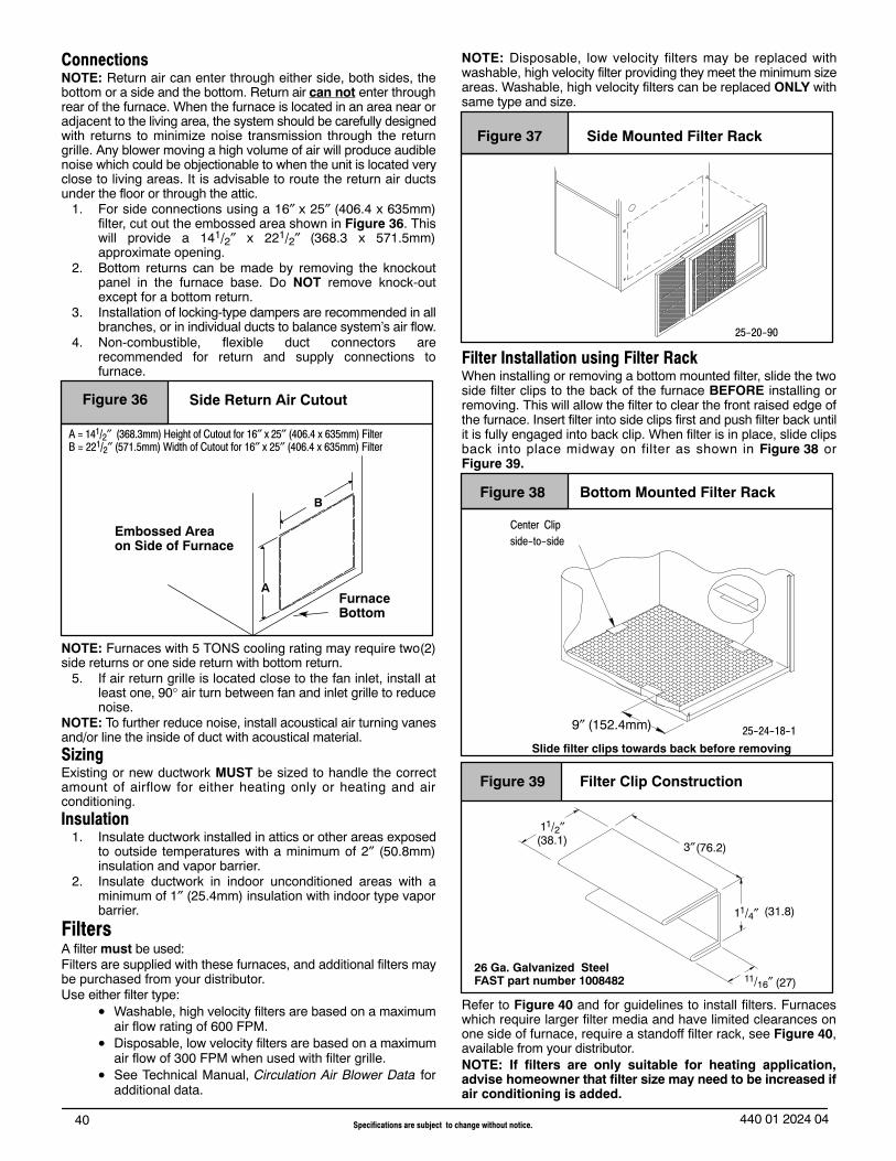
40 Specifications are subject to change without notice. 440 01 2024 04
ConnectionsNOTE: Return air can enter through either side, both sides, thebottom or a side and the bottom. Return air can not enter throughrear of the furnace. When the furnace is located in an area near oradjacent to the living area, the system should be carefully designedwith returns to minimize noise transmission through the returngrille. Any blower moving a high volume of air will produce audiblenoise which could be objectionable to when the unit is located veryclose to living areas. It is advisable to route the return air ductsunder the floor or through the attic.
1. For side connections using a 16″ x 25″ (406.4 x 635mm)filter, cut out the embossed area shown in Figure 36. Thiswill provide a 141/2″ x 221/2″ (368.3 x 571.5mm)approximate opening.
2. Bottom returns can be made by removing the knockoutpanel in the furnace base. Do NOT remove knock-outexcept for a bottom return.
3. Installation of locking-type dampers are recommended in allbranches, or in individual ducts to balance system’s air flow.
4. Non-combustible, flexible duct connectors arerecommended for return and supply connections tofurnace.
Figure 36 Side Return Air Cutout
Embossed Areaon Side of Furnace
A = 141/2″ (368.3mm) Height of Cutout for 16″ x 25″ (406.4 x 635mm) FilterB = 221/2″ (571.5mm) Width of Cutout for 16″ x 25″ (406.4 x 635mm) Filter
AFurnaceBottom
B
NOTE: Furnaces with 5 TONS cooling rating may require two(2)side returns or one side return with bottom return.
5. If air return grille is located close to the fan inlet, install atleast one, 90° air turn between fan and inlet grille to reducenoise.
NOTE: To further reduce noise, install acoustical air turning vanesand/or line the inside of duct with acoustical material.SizingExisting or new ductwork MUST be sized to handle the correctamount of airflow for either heating only or heating and airconditioning.Insulation
1. Insulate ductwork installed in attics or other areas exposedto outside temperatures with a minimum of 2″ (50.8mm)insulation and vapor barrier.
2. Insulate ductwork in indoor unconditioned areas with aminimum of 1″ (25.4mm) insulation with indoor type vaporbarrier.
FiltersA filter must be used:Filters are supplied with these furnaces, and additional filters maybe purchased from your distributor.Use either filter type:
• Washable, high velocity filters are based on a maximumair flow rating of 600 FPM.
• Disposable, low velocity filters are based on a maximumair flow of 300 FPM when used with filter grille.
• See Technical Manual, Circulation Air Blower Data foradditional data.
NOTE: Disposable, low velocity filters may be replaced withwashable, high velocity filter providing they meet the minimum sizeareas. Washable, high velocity filters can be replaced ONLY withsame type and size.
Figure 37 Side Mounted Filter Rack
25-20-90
Filter Installation using Filter RackWhen installing or removing a bottom mounted filter, slide the twoside filter clips to the back of the furnace BEFORE installing orremoving. This will allow the filter to clear the front raised edge ofthe furnace. Insert filter into side clips first and push filter back untilit is fully engaged into back clip. When filter is in place, slide clipsback into place midway on filter as shown in Figure 38 orFigure 39.
Figure 38 Bottom Mounted Filter Rack
Slide filter clips towards back before removing
25-24-18-1
Center Clipside-to-side
9″ (152.4mm)
Figure 39 Filter Clip Construction
3″
11/4″
11/2″
11/16″26 Ga. Galvanized SteelFAST part number 1008482
(38.1)
(31.8)
(76.2)
(27)
Refer to Figure 40 and for guidelines to install filters. Furnaceswhich require larger filter media and have limited clearances onone side of furnace, require a standoff filter rack, see Figure 40,available from your distributor.NOTE: If filters are only suitable for heating application,advise homeowner that filter size may need to be increased ifair conditioning is added.
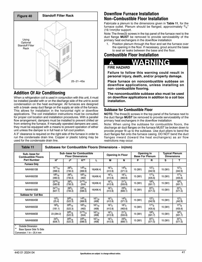
41440 01 2024 04 Specifications are subject to change without notice.
Figure 40 Standoff Filter Rack
25−21−45a
UsingOptional
Standoff FilterRack
Addition Of Air ConditioningWhen a refrigeration coil is used in conjunction with this unit, it mustbe installed parallel with or on the discharge side of the unit to avoidcondensation on the heat exchanger. All furnaces are designedwith a break−away duct flange on the supply air side of the furnace.This allows for installation in the horizontal right or downflowapplications. The coil installation instructions must be consultedfor proper coil location and installation procedures. With a parallelflow arrangement, dampers must be installed to prevent chilled airfrom entering the furnace. If manually operated dampers are used,they must be equipped with a means to prevent operation of eitherunit unless the damper is in full heat or full cool position.A 3″ clearance is required on the right side of the furnace in order torun the condensate drain line. Copper or plastic tubing may beused for the condensate drain line.
Downflow Furnace InstallationNon-Combustible Floor InstallationFabricate a plenum to the dimensions given in Table 11, for thefurnace outlet. Plenum should be flanged, approximately 3/4″(19.1mm)for support.Note: The three(3) screws in the top panel of the furnace next to theduct flange MUST be removed to provide serviceability of theprimary heat exchangers in the downflow installation
1. Position plenum through the floor and set the furnace overthe opening in the floor. If necessary, grout around the baseto seal air leaks between the base and the floor.
Combustible Floor Installation
FIRE HAZARD
Failure to follow this warning could result inpersonal injury, death, and/or property damage.
Place furnace on noncombustible subbase ondownflow applications, unless installing onnon−combustible flooring.
The noncombustible subbase also must be usedon downflow applications in addition to a coil boxinstallation.
! WARNING
Subbase for Combustible FloorNOTE: The three(3) screws in the top panel of the furnace next tothe duct flange MUST be removed to provide serviceability of theprimary heat exchangers in the downflow installationNote: When using the subbase for combustible floors, thedischarge air duct flanges on the furnace MUST be broken down toprovide proper fit up to the subbase. Use duct pliers to bend theduct flanges flat onto the furnace casing. DO NOT bend the ductflanges inward (toward the heat exchangers) as air flowrestrictions may occur.
Table 11 Subbases for Combustible Floors Dimensions − in(mm)
Sub−base for Combustible Floors
Part Number
Sub−base for CombustibleFloor Dimensions Opening In Floor
Opening InBase For Plenum
Typical PlenumDimensions
H* J* K** L M N P R S TFurnace Only
NAHH001SB1511/16(398.5)
283/4(730.3)
149/16(369.9)
16(406.4)161/4
(412.8)145/8
(371.5)15 (381)
131/2(342.9)
15 (381)131/2
(342.9)
NAHH002SB195/16(490.5)
283/4(730.3)
183/16(462)
16(406.4)161/4
(412.8)181/4
(463.6)15 (381)
171/8(435.6)
15 (381)171/8
(435.6)
NAHH003SB 2215/16(582.6)
283/4(730.3)
2113/16(554) 16(406.4) 161/4
(412.8)217/8
(555.6) 15 (381) 193/4(501.7) 15 (381) 193/4
(501.7)
NAHH010SB 2411/16(627.1)
283/4(730.3)
239/16(598.5) 16(406.4) 161/4
(412.8)235/8
(600.1) 15 (381) 221/2(571.5) 15 (381) 221/2
(571.5)
Subbase for Coil Box
NAHH004SB 153/4(25.4)
209/16(522.3)
149/16(369.9)
161/16(408)
161/4(412.8)
145/8(371.5) 15 (381) 131/2
(342.9) 15 (381) 131/2(342.9)
NAHH005SB193/8
(181.1)209/16(522.3)
183/16(462)
161/16(408)
161/4(412.8)
181/4(463.6)
15 (381)171/8
(435.6)15 (381)
171/8(435.6)
NAHH006SB 23 (284.2) 209/16(522.3)
2113/16(554)
161/16(408)
161/4(412.8)
217/8(555.6) 15 (381) 193/4
(501.7) 15 (381) 193/4(501.7)
NAHH009SB 243/4(628.7)
209/16(522.3)
239/16(598.5)
161/16(408)
161/4(412.8)
235/8(600.1) 15 (381) 221/2
(571.5) 15 (381) 221/2(571.5)
* Outside Dimension** Base Spacer Side To SideConversion: 1 in = 25.4 mm

42 Specifications are subject to change without notice. 440 01 2024 04
The Subbase for Combustible Floors MUST be used when adownflow furnace is set on a combustible floor, even when thefurnace is installed on a coil box.
1. Cut the opening in the floor according to Table 11. The holein the floor must be cut to the dimensions listed in Table 11since the base is equipped with locating tabs that center thebase over the opening.
The opening in the base is 11/4″ (31.8mm) shorter and 11/8″(28.6mm) narrower than the recommended size of the opening inthe floor. This is done to maintain clearance between the floor andthe plenum.
2. Fabricate the plenum to the dimensions given in Table 11.Note that the dimensions given are outside dimensions.
3. Set the base over the opening in the floor, centering it overthe opening. Fasten the base to the floor with screws ornails. See Figure 41, Figure 42 and Figure 43.
4. Drop the plenum through the opening in the base. Theflange of the plenum should rest on top of the subbase.
Figure 41
A = 4 1/4” (108mm) Minimum clearance from back of holeto wall or other obstruction.
A
Hole inFloor
MN
25-20-46
L
R
H
K
2″ (50.8mm)
2″(50.8mm)
1″ (25.4mm)
J
P
Exploded View of Sub−Base forFurnace ONLY
Plenum
ST
5. Position furnace or coil cabinet and furnace on subbase so italigns between the locating tabs.
Figure 42 Exploded View of Base for Downflow Cased Coil
21/2″ (63.5mm)
11/2″ (38.1mm)
Furnace
Plenum
Wood Floor
Installation ofCombustibleFloor Base
25−20−46a
Figure 43 Setting the Subbase
This subbase for combustible floors has been designed so that theheight of the subbase raises the downflow coil off the floor to alloweasy installation of the condensate drain. See Figure 44.
Condensate Line Raised by BaseFigure 44
25−20−52

43440 01 2024 04 Specifications are subject to change without notice.
Checks and AdjustmentsNOTE: Verify the input rate of the furnace.
FIRE OR EXPLOSION HAZARDFailure to follow this warning could result inpersonal injury, death and/or property damage.Turn OFF gas at shut off before connectingmanometer.
! WARNING
StartupNOTE: Refer to the start−up procedures in the “User’s InformationManual” or to the “Operating Instructions Label” on the furnace.
!
FIRE OR EXPLOSION HAZARD
Failure to follow this warning could result inpersonal injury, death, and/or property damage.
If any sparks, odors or unusual noises occur,immediately shut OFF power to furnace. Check forwiring errors or obstruction to blower.
WARNING
Gas Supply PressureGas supply pressure should be within minimum and maximumvalues listed on rating plate. Pressures are usually set by gassuppliers.
Manifold Gas Pressure Adjustments (High and Low Heat)NOTE: Make adjustment to manifold pressure with burnersoperating.
FIRE OR EXPLOSION HAZARDFailure to follow this warning could result inpersonal injury, death and/or property damage.Turn OFF gas at shut off before connectingmanometer.
! WARNING
1. With gas OFF, connect manometer to manifold pressure tapon the outlet of gas control valve. See Figure 45. Use amanometer with a 0 to 12 inches of water column range.
2. Turn gas ON. Operate the furnace on High Heat by using ajumper wire on the R to W1 & W2 thermostat connections onthe furnace control board.
3. Remove manifold pressure adjustment screw cap onfurnace gas control valve. Turn adjusting screw using 3/32hex wrench, counterclockwise to decrease the manifoldpressure and clockwise to increase pressure. SeeFigure 45.
NOTE: Adjustment screw cover MUST be replaced on gas controlvalve before reading manifold pressure and operating furnace.
Typical Gas Control Valve HoneywellFigure 45
ON
OFF
HILO
25-24-98a
HONEYWELL
INLETPressureTap − 1/8
OUTLETPressureTap − 1/8
RegulatorAdjustment Under Cap
4. Set manifold pressure to value shown in Table 7, Table 8,Table 9 or Table 10.
5. Operate the furnace on Low Heat by using a jumper wire onthe R to W1 thermostat connections on the furnace controlboard.Note: The SW1 DIP switch #3 should be in the ON positionto set the Low Heat manifold pressure. (See wiringdiagram.)
6. Repeat steps 3 and 4 for Low Heat operation.7. When the manifold pressures are properly set, replace the
adjustment screw covers on the gas control valve.8. Remove the jumper wires from the thermostat connections
on the furnace control board. Remove manometerconnection from manifold pressure tap, and replace plug ingas valve.
9. Return SW1 DIP switch #3 to previous setting.10. Check for leaks at plug.
Natural Gas Input Rating CheckNOTE: The gas meter can be used to measure input to furnace.Rating is based on a natural gas BTU content of 1,000 BTU’s percubic foot. Check with gas supplier for actual BTU content.
1. Turn OFF gas supply to all appliances and start furnace.Use jumper wire on R to W1 and W2 for High Heat.
2. Time how many seconds it takes the smallest dial on the gasmeter to make one complete revolution. Refer to Example.
3. Repeat steps 1 and 2 with jumper wire on R to W1 for LowHeat.NOTE: If meter uses a 2 cubic foot dial, divide results(seconds) by two.NOTE:SW1 DIP switch #3 must be in ON position. (SeeFurnace Wiring Diagram). Return SW1 DIP switch #3 toprevious setting after check.
Example (BTUH)Natural GasBTU Contentper cu. foot
No. of SecondsPer Hour
Time Per Cubic Foot in
Seconds
BTU PerHour
1,000 3,600 48 75,000
1,000 x 3,600 ÷ 48 = 75,000 BTUH
To Determine the appliance kW input rate from a .05m3 test dial thathas been clocked at 80 seconds for one complete revolution.

44 Specifications are subject to change without notice. 440 01 2024 04
Example (kW)
Number ofseconds per
hour
Number ofseconds per
completerotation
Size of test dial(.05m3) kW m3/h
3,600 80 .05 2.25
3,600 ÷ 80 x .05 = 7.2 m3/h
2.25m3/h x 10.35 kWh/m3 = 23.28 kW
23.28 x 3.412 = 79,431 BTU
4. Remove jumper wire from R to W1 and W2.
5. Relight all appliances and ensure all pilots are operating.
Main Burner Flame CheckAllow the furnace to run approximately 10 minutes then inspect themain burner and pilot flames. See Figure 46.Check for the following (Figure 46):
• Stable and blue flames. Dust may cause orange tips orwisps of yellow, but flames MUST NOT have solid, yellowtips.
• Flames extending directly from burner into heatexchanger.
• Flames do NOT touch sides of heat exchanger.If any problems with main burner flames are noted, it may benecessary to adjust gas pressures, or check for drafts.
Main Burner
Burner Face
10−10−78
Figure 46
NOTE: For Ignitor location see Figure 47.
Ignitor Location in(mm)Figure 47
NOTE: Flame sensor has a different orientation in all 040 & 050 models.
21/16(52.4)
5/16(8) 1/4(6.4)
Temperature Rise CheckThe blower speed MUST be set to give the correct air temperaturerise through the furnace as marked on the rating plate for both HighHeat and Low Heat operation. Temperature rise is the differencebetween supply and return air temperatures.
To check temperature rise,use the following procedure:
1. Place thermometers in supply and return air registers asclose to furnace as possible, avoiding direct radiant heatfrom heat exchangers.
2. Operate furnace on High Heat for 10 minutes with all theregisters and duct dampers open by using a jumper wire onR to W1 and W2 thermostat connections on the furnacecontrol board.Note: The SW1 DIP switch #3 should be in the on position.(See furnace wiring diagram)
3. Take readings and compare with range specified on ratingplate.
4. If the temperature rise is not in the correct range, the blowerspeed must be changed. A higher blower speed will lowerthe temperature rise. A lower blower speed will increase thetemperature rise.
5. Repeat steps 2 thru 4 with the furnace operating on LowHeat for 10 minutes by using a jumper wire on the R to W1thermostat connections on the furnace control board.
6. Remove the jumper wire after the adjustments arecomplete. Return SW1 DIP switch #3 to previous setting.
Blower Adjustments (*9MPT)Changing Blower Speed
ELECTRICAL SHOCK HAZARD
Failure to follow this warning could result inpersonal injury or death.
Turn OFF power, lockout, and tag switch with asuitable warning label, to furnace beforechanging speed taps.
! WARNING
NOTE: The speed taps that the manufacturer sets from the factoryfor this product are based on a nominal 400 CFM (189 L/s) per toncooling and the basic mid range on the temperature rise forheating.
Since the manufacturer cannot establish the static pressurethat will be applied to the unit, it is the responsibility of theinstaller dealer/contractor to select the proper speed taps forthe application when the unit is installed.
If it is necessary to change speeds, refer to steps below.
!
REDUCED FURNACE LIFE HAZARDFailure to follow this caution may result in reducedfurnace life.Use ONLY the blower motor speed taps insertindicated in the Circulation Air Blower Data forsetting air temperature rise.
CAUTION
1. Refer to Furnace Wiring Diagram for location of the heatingand cooling speed taps located on the furnace control boardas well as location of unused blower motor speed leads.Use the chart (Table 12) to determine the blower motorspeed settings.
Table 12 Blower Speed ChartWire Color Motor Speed
Black HighOrange* Med−High
Blue MediumRed Low
* Med−High speed may not be provided on all models.
45440 01 2024 04 Specifications are subject to change without notice.
2. Change the heat or cool blower motor speed by removing themotor lead from the “HI HEAT or LO HEAT” or “COOL”terminal and replace it with the desired motor speed lead fromthe “M1” or “M2” location. Connect the wire previouslyremoved from the “HI HEAT or LO HEAT” or “COOL” terminalto the vacated “M1” or “M2” terminal.
3. If the same speed must be used for both heating and cooling,remove the undesired motor speed lead from the “HI HEAT orLO HEAT” or “Cool” terminal and connect that lead to theopen terminal at “M1” or “M2” location or tape off. Attach ajumper between the “HI HEAT or LO HEAT” and “Cool”terminals and the remaining motor speed lead.
Note: When using the same speed on motors with (4) speedleads, it will be necessary to tape off the terminal of the motorspeed lead removed from the “HI HEAT or LO HEAT” or“Cool” terminal with electrical tape since an open terminal willnot be available at the “M1” or “M2” location.
Continuous-Fan using “G”Energizing the ”G” terminal on the furnace control board providescontinuous fan operation. This is done by connecting the Gterminal of the thermostat to the G terminal on the furnace controlboard. When the FAN switch is turned from auto to ON the fan willoperate continuously at ”LO HEAT” speed. EAC will be energizedin this mode.
NOTE: In heating, the fan will turn off during furnace ignition andwarm up then restart at heating speed.
Hard-Wired Continuous FanA terminal is provided on the furnace control board located in thecirculating air blower compartment for operation of the continuousfan option. This connection is intended for the low speed motor tap,and has a lower contact rating (8 amps) than the heat and cool taps.When the low speed blower lead is connected to this terminal, it willprovide low speed blower operation whenever the other threespeeds (“HI HEAT or LO HEAT” or COOL) are not energized.
Thoroughly check the system after modification to ensure theproper operation of the circulating air blower in all modes ofoperation.
Separate Speed Selections for Low Heat, High Heat,Cool, and Continuous-FanConnect low speed lead from circulating air motor to the “CONT”terminal at the furnace control board. The appropriate motor leadsshould already be connected to the “HI HEAT and LO HEAT” and“COOL” terminals.
Heating and Continuous-Fan Speed the SameIf it is necessary to operate the Low Heat speed andcontinuous−fan speed using the same blower speed, connect ajumper between the “LO HEAT” and “CONT FAN” terminals onthe furnace control board.
Note: There should be only ONE motor lead going to the “LOHEAT” and “CONT FAN” terminals.
Blower Adjustments (*9MPV, *9MVX)Changing Blower Speed
ELECTRICAL SHOCK HAZARD
Failure to follow the warning could result inpersonal injury or death.
Turn OFF power, lockout, and tag switch with asuitable warning label, to furnace before changingblower speed.
! WARNING
NOTE: The blower speeds that the manufacturer sets from thefactory for this product are based on a nominal 400 CFM (189 L/s)per ton cooling and the mid range on the temperature rise forheating.
Since the manufacturer cannot predict the static pressurethat will be applied to the furnace, it is the responsibility of theinstalling dealer/contractor to select the proper speeds forthe application when the furnace is installed.
If it is necessary to change speeds, refer to steps below.
1. The 115 VAC power supply to the furnace must be turnedOFF before making adjustments to the motor.
NOTE: Allow at least 1 minute before restoring power to thefurnace after making Blower Control changes.
2. The heating, cooling and continuous blower speeds can beadjusted by changing the SW2 DIP switch settings that arelocated on the Tap Select Interface Board (see Figure 48).
* Switches #1 and #2 adjust the continuous blower speeds.Switches #3 and #4 adjust the heating speed.Switches #5 and #6 adjust the cooling speed.Switches #7 and #8 adjust the cooling speed on/off delayprofiles. See the “Technical Support Manual” for the switchsettings for the desired airflow rates for the installation.The jumper J1 is used to slightly increase (+) or decrease(−) or not change (NOM) the blower speed selected fromSW2. J1 effects BOTH cooling and heating airflow.
* To set continuous blower to run in high cooling speed for alllow cooling (Y1) calls, DIP switch settings #1 to 1=ON and#2 to 0=OFF or DIP switches #1 to 1=ON and #2 to 1=ON.
* To set continuous blower to operate normally in low cooling(Y1), DIP switch settings #1 to 0=OFF and #2 to 0=OFF or#1 to 0=OFF and #2 to 1=ON.
Continuous-Fan using “G”Energizing the ”G” terminal on the furnace control board providescontinuous fan operation. This is done by connecting the Gterminal of the thermostat to the G terminal on the furnace controlboard. When the FAN switch is turned from auto to ON the fan willoperate continuously at airflow selected by DIP SW2 switch #1 andDIP SW2 switch #2. EAC will be energized in this mode.
NOTE: In heating, the fan will not turn off during furnace ignitionand warm up.
Hard Wired Continuous Fan OperationNot available for variable speed models.

46 Specifications are subject to change without notice. 440 01 2024 04
ON = 1
1 8
OFF = 0
Variable Speed (*9MPV, *9MVX) Tap Select Interface Board (TSIB)Figure 48
Furnace Maintenance
FIRE, EXPLOSION, OR CARBON MONOXIDEHAZARDS
Failure to have the furnace inspected andmaintained could result in personal injury, death,and/or property damage.
It is recommended that the furnace be inspectedand serviced on an annual basis (before the heatingseason) by a qualified service technician.
See “User’s Information Manual”.
! WARNING
See “User’s Information Manual”.
ELECTRICAL SHOCK, FIRE OR EXPLOSION HAZARD
Failure to follow this warning could result inpersonal injury, death, and/or property damage.
• Before servicing, disconnect all electrical power to furnace.
• When servicing controls, label all wires prior todisconnecting. Reconnect wires correctly.
• Verify proper operation after servicing.
! WARNING

47440 01 2024 04 Specifications are subject to change without notice.
Sequence of Operation & Diagnostics (*9MPT)The following is the normal operating sequence at factory default settings (SW1 OFF/ON/OFF)
Cooling (Y) Request:24VAC signals applied to Y/Y2 & G terminals of FCB (furnace control board).• Cool motor speed is energized after 5 second Cool Fan On Delay time.
Y/Y2 & G signals removed from FCB• Cool motor speed is de−energized after 90 second Cool Fan Off Delay time.
NOTE: DEHUM not available on the *9MPT models.
Continuous Circulating Fan (G) Request:24VAC signal applied to G terminal of FCB.• Low−Heat motor speed is energized without delay.
G signal removed from FCB.• Low−Heat motor speed is de−energized after 5 second delay.
NOTE 1) Furnace de−energizes the fan during the heat exchanger warm−up period on a call for Heating that occurs during a G requestunless a blower motor lead is connected to the CONT FAN terminal on the FCB, in which case see NOTE 2)NOTE 2) Heating or Cooling requests received during a Fan request cause the fan speed to change to the appropriate heat or cool speedafter the Fan On Delay time expires. The fan returns to continuous circulating speed after the selected Fan Off Delay time expires followingloss of the Heating or Cooling request.
Continuous Circulating Fan Hard-Wired (Cont) Request:Field selected low speed motor tap installed on ”CONT FAN” terminal. • Low speed is energized when power applied to furnace. Operates at this speed continuously while there are no other blower demands from furnace control board. Fan demands from furnace control board for heat, cool or ”G” will override hard−wiredspeed tap.
NOTE 3) EAC is NOT active for hard−wired mode but IS active for fan demands from furnace control board for heat, cool and “G”.
Heating (W1) Request (single stage thermostat operation, SW1 DIP switch #3 must be in OFFposition) (see furnace wiring diagram):
24VAC signal applied to W1 terminal of FCB.• Inducer motor turns on at high speed.• Following a 15 second prepurge delay after the low pressure switch closes, the ignitor begins a 17 second warm up.• The gas valve is energized, the main burners light at Low Heat rate and flame is sensed.• The ignitor is de−energized, and the inducer drops to low speed after the main burners ignite.• The FCB will delay Low Heat blower operation for the 45−second Low Heat Fan On Delay time, timed from
the opening of the gas valve.• If the W1 request is still present after 12 minutes, timed from the opening of the gas valve, the inducer switches to high speed,
closing the high pressure switch, then the High Heat solenoid energizes, and the fan switches to High Heat speed.
W1 signal removed from FCB.• The gas valve de−energizes and the main burners go out.• The inducer runs at its present speed for a 15 second postpurge period.• The fan runs at its present speed.• The fan de−energizes after the selected Heat Fan Off Delay time expires, timed from the gas valve de−energizing.
NOTE 4) If a new Heating request arrives while the control is waiting in the Heat Fan Off Delay time, the FCB will wait for the selected HeatFan Off Delay then start a new heating cycle as long as the heat call remains.
Heating Request (W1 & W2) (two-stage thermostat operation, SW1 DIP switch #3 must be in ONposition) (see furnace wiring diagram):
24VAC signal applied to W1 terminal of FCB.• Same response as single stage thermostat operation (fan uses Low Stage Heat On Delay) described above except the control
will not go to High Heat rate, and High Heat Fan speed unless a W2 signal is applied.
24VAC signal applied to W1 and W2 terminals of FCB.• Same light−off routine as described for the signal stage thermostat operation except main burners light at High Heat rate, the
inducer remains on high speed after ignition, and the FCB will delay blower operation at the High Heat Fan speed for 30 second On Delay time.
NOTE 5) The FCB responds without delay to the presence or loss of W2 (with W1 constant). W1 & W2 result in high inducer, High Heatrate, and High Heat Fan speed. W1 only results in low inducer, Low Heat rate, and Low Heat Fan speed.

48 Specifications are subject to change without notice. 440 01 2024 04
Heating Request with Gas Shut Off:24 VAC signal applied to W1 terminal of FCB.The FCB will attempt 4 cycles for ignition then go to soft lockout for 3 hours, and then try for ignition again as long as the heat callremains. Power reset will clear lockout.• Inducer motor turns on at high speed.• Following a 15 second prepurge delay, the ignitor begins warm up.• The ignitor glows red−hot for 22 seconds, then turns off. The FCB flashes error code 6.• The ignitor stays off for 17 seconds, then begins to warm up again.• The ignitor glows red hot for 22 seconds then turns off. The FCB continues flashing error code 6.• The ignitor stays off for 17 seconds, then begins to warm up again.• The ignitor glows red hot for 22 seconds then turns off. The FCB continues flashing error code 6.• The ignitor stays off for 17 seconds, then begins to warm up again.• The ignitor glows red hot for 22 seconds then turns off. The FCB proceeds to soft lockout. Stops flashing
error code 6, and begins flashing error code 6 + 1.· The inducer motor de−energizes after a 15 second post purge.
Furnace Control Board Diagnostic Codes (See Figure 49):OFF = 24VAC or 115VAC is off, fuse is openHeartbeat = Normal operation or no previous Diagnostic CodeON SOLID = Soft Lockout − Furnace Control Error (1 hr delay) If code repeats immediately following power reset then replace control1 Flash = Not used2 Flashes = Pressure switch(es) closed when should be open3 Flashes = Low pressure switch open when should be closed4 Flashes = Limit or flame roll−out switch open (less than 2 minutes)5 Flashes = Flame sensed out of sequence6 Flashes = Failure to ignite or flame sense lost while running6 + 1 Flashes = Soft Lockout − Max of four trials for ignition reached (3hr delay) 7 Flashes = Soft Lockout − Limit or flame roll−out switch open longer than 2 minutes (1 hr delay)
(roll−out switch requires manual reset)8 Flashes = Permanent Lockout − Gas valve relay contact stuck closed or miswired gas valve (power reset only)9 Flashes = High pressure switch open when should be closed10 Flashes = Line voltage polarity or improper transformer phasing on twinned applications
NOTE: The 6 + 1 designation indicates a combination of flashcodes.
* If status code recall is needed, briefly (2−3 seconds) remove thenreconnect one limit switch wire (main or rollout) to display laststored status code. Do not remove power or blower door beforeinitiating status code recall or code will be lost. Code isautomatically cleared after 72 hours or upon power reset.
* Proper flame sense microamps: 0.7 microamps D.C. minimum,2.0 − 4.0 microamps nominal
Figure 49 Control Board
DIP Switch See “WiringDiagram” for switch settings
FUSE
25−24−74
115VACHUM
DEHUM
Diagnostic Light
24 VACHUM
EAC
HUMIDIFIER − The 24VAC HUM is energized when the low pressure switch closes on a call for heat. The 115V HUM (called HUM onControl) is energized when the inducer is energized.
ELECTRONIC AIR CLEANER − EAC is energized when there is a blower speed call. It is NOT energized when blower operates in thehard−wired continuous fan mode.

49440 01 2024 04 Specifications are subject to change without notice.
Wiring Diagram *9MPT (Two−Stage Heating with PSC Motor)

50 Specifications are subject to change without notice. 440 01 2024 04
Sequence of Operation & Diagnostics (*9MPV, *9MVX)The following is the normal operating sequence at factory default settings (SW1 OFF/ON/OFF, SW2 all OFF)
NOTE: SW1 DIP switches (G, Y/Y2, W1, W2 thermostat terminals) and DEHUM (1/4” male quick connect terminal) are located on the FCB. SW2 DIP switches and Y1 and O thermostat terminals are located on the TSIB.
Low Cooling (Y1) Request:24VAC signals applied to Y1 & G terminals of TSIB (Tap Select Interface Board) and FCB (Furnace Control Board), respectively. • Low Cooling motor speed is energized after 5 second Cool Fan On Delay time.Y1 & G signals removed from TSIB and FCB• Low Cooling motor speed is de−energized after 90 second Cool Fan Off Delay time.Cooling (Y1) and dehumidification (DEHUM) requests:• 24 VAC signals applied to Y1, DEHUM & G terminals of TSIB and FCB.
• Same operation as the cooling (Y1) request, except the cooling airflow is reduced 20% to compensate for highhumidity conditions during cooling operation. The low cooling airflow returns to the normal setting after the DEHUM signal isremoved.
High Cooling (Y1 & Y/Y2) or (Y/Y2) Request:24VAC signals applied to Y1 & Y/Y2 & G or Y/Y2 & G terminals of FCB (Furnace Control Board).• High Cooling motor speed is energized after 5 second Cool Fan On Delay time.Y1 & Y/Y2 & G or Y/Y2 & G signals removed from TSIB and FCB• High Cooling motor speed is de−energized after 90 second Cool Fan Off Delay time.High Cooling (Y1 & Y/Y2 or Y/Y2) and dehumidification (DEHUM) requests:• 24 VAC signals applied to Y1 & Y/Y2 or Y/Y2, DEHUM, & G terminals of TSIB and FCB.
• Same operation as the high cooling (Y1 & Y/Y2 or Y/Y2) request, except the cooling airflow is reduced 20% to compensate for highhumidity conditions during cooling operation. The high cooling airflow returns to the normal setting after the DEHUM signal isremoved.
Low or high cooling and O terminal (Heat Pump mode):• If the J2 jumper is in the AC/HP EFFICIENCY position, there will be no change in blower airflow regardless of the O terminal being
energized or de−energized.
• If the J2 jumper is in the HP COMFORT position, then there will be a 10% reduction in airflow when the O terminal is de−energized(HP heating) and no airflow reduction when O is energized (HP cooling).
NOTE 1) The motor has been set up to recognize the O terminal as energized during cooling calls (reversing valve energized for cooling).
Continuous Circulating Fan (G) Request:24VAC signal applied to G terminal of FCB.• Continuous fan speed is energized without delay.G signal removed from FCB.• Continuous fan speed is de−energized after 5 second delay.
NOTE 2) Heat or Cooling requests received during a Fan request, cause the fan speed to change to the appropriate heat or cool speed afterthe Fan On Delay time expires. The fan returns to continuous circulating speed after the selected Fan Off Delay time expires following lossof the Heating or Cooling request.NOTE 3) Hard−wire option not available for variable speed models.NOTE 4) Continuous blower selection DIP 10 and 11 will cause the blower to run in high cooling speed for all low cooling (Y1) calls.Continuous blower DIP settings of 00 and 01 will allow low cooling (Y1) calls to operate normally.
Heating (W1) Request (single stage thermostat operation, SW1 DIP switch #3 on the FCB mustbe in OFF position) (see furnace wiring diagram):
24VAC signal applied to W1 terminal of FCB.• Inducer motor turns on at high speed.• Following a 15 second prepurge delay after the low pressure switch closes, the ignitor begins a 17 second warm up.• The gas valve is energized, the main burners light at Low Heat rate.• The ignitor is de−energized, and the inducer drops to low speed after the main burners ignite.• The FCB will delay Low Heat blower operation for the 45−second Low Heat Fan On Delay time timed from the opening of the gas
valve.• If the W1 request is still present after 12 minutes, timed from the opening of the gas valve, the inducer switches to high speed,
closing the high pressure switch, then the High Heat solenoid energizes, and the fan switches to High Heat speed.
W1 signal removed from FCB.• The gas valve de−energizes and the main burners go out.• The inducer runs at its present speed for a 15 second postpurge period.

51440 01 2024 04 Specifications are subject to change without notice.
• The fan runs at its present speed.• The blower de−energizes after the selected Heat Fan Off Delay time expires timed from the gas valve de−energizing.
NOTE 5) If a new Heating request arrives while the control is waiting for the Heat Fan Off Delay time to expire, the FCB will wait for theselected Heat Fan Off Delay, and then start a new heating cycle.
Heating (W1 & W2) Request (two-stage thermostat operation, SW1 DIP switch #3 must be in ONposition) (see furnace wiring diagram):
24VAC signals applied to W1 terminal of FCB.• Same response as single stage thermostat operation described above except the burners, inducer, and blower will not go to high
heat rate, and High Heat Fan speed unless a W2 signal is applied.
24VAC signal applied to W1 and W2 terminals of FCB.• Same light−off routine as described for the signal stage thermostat operation except burners light at High Heat rate, the inducer
remains on high speed after ignition, and the FCB will delay High Heat blower operation for the 30−second High Heat FanOn Delay.
NOTE 6) The FCB responds without delay to the presence or loss of W2 (with W1 constant). W1 & W2 result in high inducer, High Heatrate, and High Heat Fan speed. W1 only results in low speed inducer, Low Heat rate, and Low Heat Fan speed.
Heating Request with Gas Shut Off:24 VAC signals applied to W1 terminal of FCB.The FCB will attempt 4 cycles for ignition then go to soft lockout for 3 hours, and then try for ignition again as long as the heat callremains. Power reset will clear lockout.• Inducer motor turns on at high speed.• Following a 15 second prepurge delay after the low pressure switch closes, the ignitor begins warm up.• The ignitor glows red−hot for 22 seconds, then turns off. The FCB flashes error code 6.• The ignitor stays off for 17 seconds, then begins to warm up again.• The ignitor glows red hot for 22 seconds then turns off. The FCB continues flashing error code 6.• The ignitor stays off for 17 seconds, then begins to warm up again.• The ignitor glows red hot for 22 seconds then turns off. The FCB continues flashing error code 6.• The ignitor stays off for 17 seconds, then begins to warm up again.• The ignitor glows red hot for 22 seconds then turns off. The FCB proceeds to soft lockout. Stops flashing
error code 6, and begins flashing error code 6 + 1.• The inducer motor de−energizes 15 seconds after error code 6 + 1 starts flashing.
Furnace Control Board Diagnostic Codes (See Figure 49):OFF = 24VAC or 115VAC is off, fuse is openHeartbeat = Normal operation or no previous Diagnostic CodeON SOLID = Soft Lockout − Furnace Control Error (1 hr delay) If code repeats immediately following power reset then replace control1 Flash = Not used2 Flashes = Pressure switch(es) closed when should be open3 Flashes = Low pressure switch open when should be closed4 Flashes = Limit or flame roll−out switch open (less than 2 minutes)5 Flashes = Flame sensed out of sequence6 Flashes = Failure to ignite or flame sense lost while running6 + 1 Flashes = Soft Lockout − Max of four trials for ignition reached (3 hr delay) 7 Flashes = Soft Lockout − Limit or flame roll−out switch open longer than 2 minutes (1 hr delay)
(roll−out switch requires manual reset)8 Flashes = Permanent Lockout − Gas valve relay contact stuck closed or miswired gas valve (power reset only)9 Flashes = High pressure switch open when should be closed10 Flashes = Improper transformer phasing on twinned applications or improper line voltage polarity.* If status code recall is needed, briefly (2−3 seconds) remove then reconnect one limit switch wire (main or rollout) to display last storedstatus code. Do not remove power or blower door before initiating status code recall or code will be lost. Code is automatically cleared after72 hours or upon power reset.* Proper flame sense microamps: 0.7 microamps D.C. minimum, 2.0 − 4.0 microamps nominalNOTE 7) Continuous blower selection DIP 10 and 11 will cause the blower to run in high cooling speed for all low cooling (Y1) calls.Continuous blower DIP settings of 00 and 01 will allow low cooling (Y1) calls to operate normally.
HUMIDIFIER − The 24VAC HUM is energized when the low pressure switch closes on a call for heat. The 115V HUM (called HUM onControl) is energized when the inducer is energized.
ELECTRONIC AIR CLEANER − EAC is energized when there is a blower speed call. It is NOT energized when blower operates in thehard−wired continuous fan mode.

52 Specifications are subject to change without notice. 440 01 2024 04
Wiring Diagram *9MPV, *9MVX (Variable Speed Blower Motor)
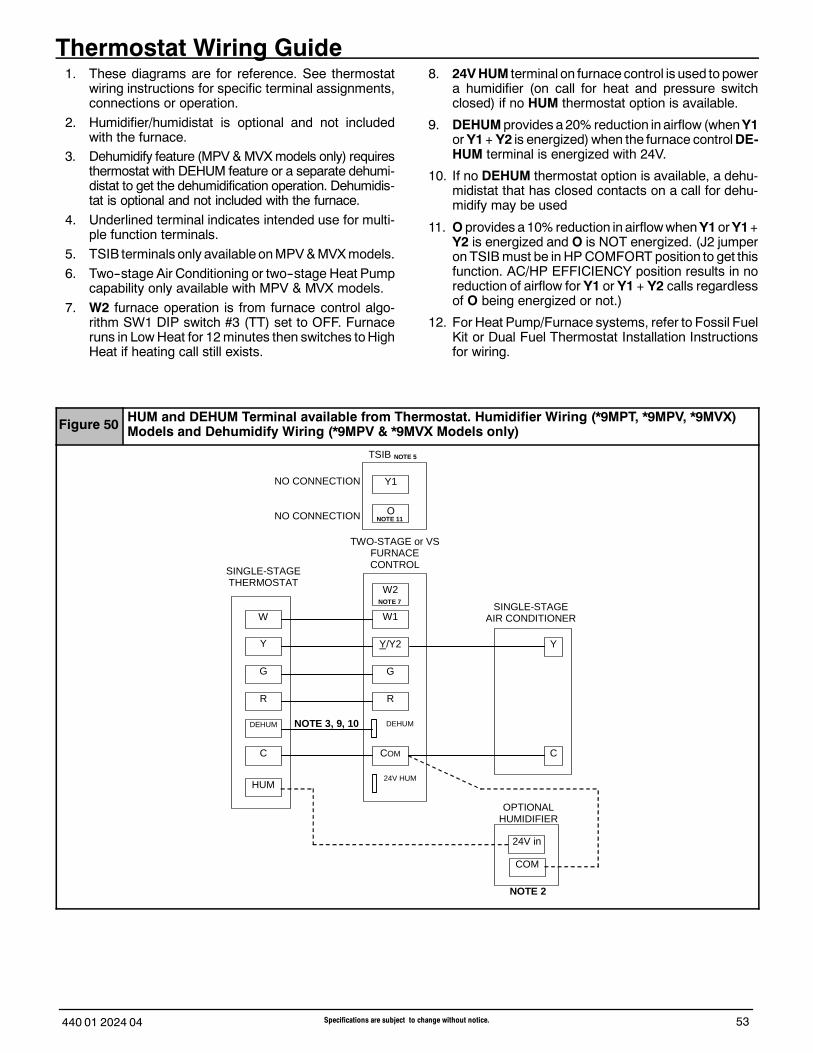
53Specifications are subject to change without notice.440 01 2024 04
Thermostat Wiring Guide1. These diagrams are for reference. See thermostat
wiring instructions for specific terminal assignments,connections or operation.
2. Humidifier/humidistat is optional and not includedwith the furnace.
3. Dehumidify feature (MPV&MVXmodels only) requiresthermostat with DEHUM feature or a separate dehumi-distat to get the dehumidification operation. Dehumidis-tat is optional and not included with the furnace.
4. Underlined terminal indicates intended use for multi-ple function terminals.
5. TSIB terminals only available onMPV&MVXmodels.
6. Two--stage Air Conditioning or two--stage Heat Pumpcapability only available with MPV & MVX models.
7. W2 furnace operation is from furnace control algo-rithm SW1 DIP switch #3 (TT) set to OFF. Furnaceruns in LowHeat for 12minutes then switches toHighHeat if heating call still exists.
8. 24V HUM terminal on furnace control is used to powera humidifier (on call for heat and pressure switchclosed) if no HUM thermostat option is available.
9. DEHUM provides a20% reduction in airflow (whenY1orY1+ Y2 is energized)when the furnace controlDE-HUM terminal is energized with 24V.
10. If no DEHUM thermostat option is available, a dehu-midistat that has closed contacts on a call for dehu-midify may be used
11. O provides a10% reduction in airflowwhenY1orY1+Y2 is energized and O is NOT energized. (J2 jumperon TSIBmust be in HPCOMFORT position to get thisfunction. AC/HP EFFICIENCY position results in noreduction of airflow for Y1 or Y1 + Y2 calls regardlessof O being energized or not.)
12. For Heat Pump/Furnace systems, refer to Fossil FuelKit or Dual Fuel Thermostat Installation Instructionsfor wiring.
Figure 50 HUM and DEHUM Terminal available from Thermostat. Humidifier Wiring (*9MPT, *9MPV, *9MVX)Models and Dehumidify Wiring (*9MPV & *9MVX Models only)
NOTE 3, 9, 10
Y
W
G
R
W1
Y/Y2
G
R
C COM
TWO-STAGE or VS FURNACE CONTROL
SINGLE-STAGE AIR CONDITIONER
Y
C
SINGLE-STAGE THERMOSTAT
W2
24V in
COM
OPTIONAL HUMIDIFIER
DEHUM
HUM 24V HUM
DEHUM
NO CONNECTION
NO CONNECTION
NOTE 2
NOTE 11
NOTE 7
Y1
O
TSIB NOTE 5
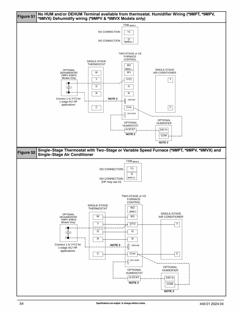
440 01 2024 0454 Specifications are subject to change without notice.
Figure 51 No HUM and/or DEHUM Terminal available from thermostat. Humidifier Wiring (*9MPT, *9MPV,*9MVX) Dehumidify wiring (*9MPV & *9MVX Models only)
Y
W
G
R
W1
Y/Y2
G
R
C COM
TWO-STAGE or VS FURNACE CONTROL
SINGLE-STAGE AIR CONDITIONER
Y
C
SINGLE-STAGE THERMOSTAT W2
OPTIONAL HUMIDISTAT
H-STAT 24V in
COM
OPTIONAL HUMIDIFIER
OPTIONAL DEHUMIDISTAT
(*MPV Models Only)
Connect 1 to Y/Y2 for 1-stage AC/ HP
applications
1 2
24V HUM
DEHUM
Y1
O
TSIB NOTE 5
NO CONNECTION
NO CONNECTION
NOTE 3
NOTE 2
NOTE 2
NOTE 11
NOTE 7OPTIONAL
DEHUMIDISTAT(*MPV &*MVXModels Only)
Figure 52 Single--Stage Thermostat with Two--Stage or Variable Speed Furnace (*9MPT, *9MPV, *9MVX) andSingle--Stage Air Conditioner
Y
W
G
R
W1
Y/Y2
G
R
C COM
TWO-STAGE or VS FURNACE CONTROL
SINGLE-STAGE AIR CONDITIONER
Y
C
SINGLE-STAGE THERMOSTAT W2
NOTE 7
Y1
O
TSIB NOTE 5
OPTIONAL HUMIDISTAT
H-STAT 24V in COM
OPTIONAL HUMIDIFIER
Connect 1 to Y/Y2 for 1-stage AC/ HP
applications
1 2
NO CONNECTION
NO CONNECTION (HP may use O)
DEHUM
24V HUM
NOTE 3
NOTE 2
NOTE 2
OPTIONAL DEHUMIDISTAT
(*MPV Models Only)
NOTE 11
OPTIONALDEHUMIDISTAT(*MPV &*MVXModels Only)

55Specifications are subject to change without notice.440 01 2024 04
Figure 53 Two--Stage Thermostat with Two--Stage Furnace or Variable Speed Furnace (*9MPT, *9MPV, *9MVXModels) and Single--Stage Air Conditioner
OPTIONAL DEHUMIDISTAT
(*MPV Models Only) If no DEHUM from
thermostat available
Y1
W1
Y/Y2
G
R
24V HUM
COM
VS FURNACE CONTROL
SINGLE STAGE AIR CONDITIONER
Y
C
TWO-STAGE THERMOSTAT
W2
Y1
Y2
G
R
C
W2
NOTE 3, 9, 10
O
W1
TSIB NOTE 5
DEHUM
HUM 24V in COM
OPTIONAL HUMIDIFIER
Connect 1 to Y1 for 2-stage AC-HP applications.
OR Connect 1 to Y/Y2 for
1-stage AC- HP applications
1 2
DEHUM
NOTE 2
NOTE 11
NOTE 7
OPTIONALDEHUMIDISTAT(*MPV &*MVXModels Only)
Figure 54 Two--Stage Thermostat with Variable Speed Furnace (*9MPV & *9MVX Models only)and Two--Stage Air Conditioner
OPTIONAL DEHUMIDISTAT
(*MPV Models Only) If no DEHUM from
thermostat available
Y1
W1
Y/Y2
G
R
24V HUM
COM
VS FURNACE CONTROL
TWO-STAGE AIR CONDITIONER
Y2
C
Y1
TWO-STAGE THERMOSTAT
W2
Y1
Y2
G
R
C
W2
NOTE 3, 9, 10
O
W1
TSIB NOTE 5
DEHUM
HUM 24V in COM
OPTIONAL HUMIDIFIER
Connect 1 to Y1 for 2-stage AC-HP applications.
OR Connect 1 to Y/Y2 for
1-stage AC- HP applications
1 2
DEHUM
NOTE 11
NOTE 2
OPTIONALDEHUMIDISTAT(*MPV &*MVXModels Only)
International Comfort Products, LLC
Lewisburg, Tennessee 37091 USA