Embed Size (px)
Citation preview
Fire
Loop
ed_I
nsG
_F00
4_1-
08,C
opyr
ight
©20
08U
pono
r,In
c.Pr
inte
din
the
Uni
ted
Stat
es
Uponor, Inc.5925 148th Street WestApple Valley, MN 55124 USATel: (800) 321-4739Fax: (952) 891-1409Web: www.uponor-usa.com
Uponor Ltd.655 Park StreetRegina, SK S4N 5N1 CANADATel: (888) 994-7726Fax: (800) 638-9517Web: www.uponor.ca
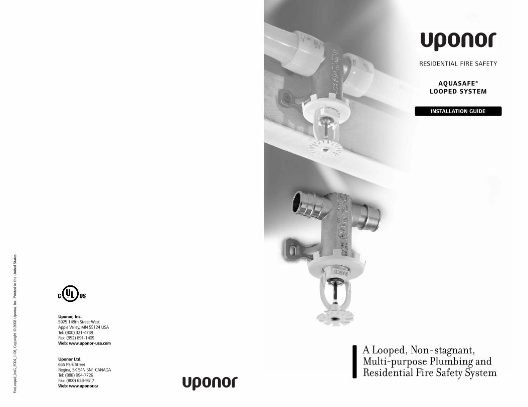
INSTALLATION GUIDE
RESIDENTIAL FIRE SAFETY
AQUASAFE®LOOPED SYSTEM
A Looped, Non-stagnant,Multi-purpose Plumbing andResidential Fire Safety System
This installation guide is published for architects, engineers, building officials, plumbing professionals and Authorities Having Jurisdiction (AHJ) interested in Uponor fire safety systems. This guide describes therecommendations for installing the system in one- and two-family dwellings.
The Uponor AQUASAFE® Looped System includes Wirsbo AQUAPEX®tubing and Wirsbo AQUAPEX plus tubing. Both Wirsbo AQUAPEX tubingand Wirsbo AQUAPEX plus tubing carry the NSF-pw seal for use in hot and cold potable water plumbing systems and are listed by UnderwritersLaboratories Inc. in accordance with UL 1821 and ULC/ORD C199P whenintended for use in an Uponor fire safety system.
Note: For readability, this document will refer to both Wirsbo AQUAPEXtubing and Wirsbo AQUAPEX plus tubing as Wirsbo AQUAPEX tubing when information applies to both.
Uponor took reasonable efforts in collecting, preparing and providing quality information and material in this document. However, systemenhancements may result in modification of features or specifications without notice. For the most current technical information, go to theUponor website at www.uponor-usa.com.
Uponor is not liable for installation practices that deviate from this document or are not acceptable practices within the mechanical trades.
Refer to the Uponor Professional Plumbing Installation Guide or theUponor Radiant Floor Heating Installation Guide to install WirsboAQUAPEX tubing in plumbing or hydronic radiant heating applications.
Please direct any questions regarding the suitability of an application or aspecific design to a local Uponor representative by calling (800) 321-4739(U.S.) or (888) 994-7726 (Canada).
Note: Some information within this installation guide may still be pendingformal documentation from Underwriters Laboratories (UL).
Uponor AQUASAFE® Looped System Installation GuidePublished by Uponor, Inc.5925 148th Street WestApple Valley, MN 55124 USATel: (800) 321-4739Fax: (952) 891-1409www.uponor-usa.com
© 2008 Uponor, Inc.All Rights Reserved.
First Printing, January 2008Printed in the United States of America
iUponor AQUASAFE® Looped System Installation Guidewww.uponor-usa.com • www.uponor.ca
Table of Contents
Section 1 — AQUASAFE® Looped SystemSystem Overview . . . . . . . . . . . . . . . . . . . . . . . . . . . . . . . . . . . . . . . . . . 1System Features and Benefits . . . . . . . . . . . . . . . . . . . . . . . . . . . . . . . . 2Material Standards, Ratings and Certifications . . . . . . . . . . . . . . . . . . . 2Model Code Approvals, Material Standards and Certifications . . . . . . . 3Listing Requirements and Handling Guidelines . . . . . . . . . . . . . . . . . . . 3Necessary Parts and Tools . . . . . . . . . . . . . . . . . . . . . . . . . . . . . . . . . . . 5Tubing Identification . . . . . . . . . . . . . . . . . . . . . . . . . . . . . . . . . . . . . . . 5System Design Program . . . . . . . . . . . . . . . . . . . . . . . . . . . . . . . . . . . . . 5
Section 2 — Working With Wirsbo AQUAPEX®Tubing
Reforming Kinked Tubing . . . . . . . . . . . . . . . . . . . . . . . . . . . . . . . . . . . 7Storing and Handling PEX . . . . . . . . . . . . . . . . . . . . . . . . . . . . . . . . . . . 8Bending PEX . . . . . . . . . . . . . . . . . . . . . . . . . . . . . . . . . . . . . . . . . . . . . 8Uncoiling PEX . . . . . . . . . . . . . . . . . . . . . . . . . . . . . . . . . . . . . . . . . . . . 8
Section 3 — Sprinkler OptionsConcealed Sprinklers . . . . . . . . . . . . . . . . . . . . . . . . . . . . . . . . . . . . . . . 9Recessed Pendent Sprinklers . . . . . . . . . . . . . . . . . . . . . . . . . . . . . . . . 10Recessed Horizontal Sidewall Sprinklers . . . . . . . . . . . . . . . . . . . . . . . 10
Section 4 — The Uponor Sprinkler AdapterFitting
Installing the Fitting . . . . . . . . . . . . . . . . . . . . . . . . . . . . . . . . . . . . . . 11
Section 5 — Making the ProPEX® FittingMaking ProPEX Connections . . . . . . . . . . . . . . . . . . . . . . . . . . . . . . . . 15Important Tips for a Proper ProPEX Connection . . . . . . . . . . . . . . . . . 17Making 3⁄8" ProPEX Connections . . . . . . . . . . . . . . . . . . . . . . . . . . . . . 18Using the ProPEX® Auto Rotation Adapter . . . . . . . . . . . . . . . . . . . . . 18Disconnecting a ProPEX Brass Fitting . . . . . . . . . . . . . . . . . . . . . . . . . 20Troubleshooting ProPEX Connections . . . . . . . . . . . . . . . . . . . . . . . . . 20Cold-weather Expansions . . . . . . . . . . . . . . . . . . . . . . . . . . . . . . . . . . 22Proper Expander Tool and Head Maintenance . . . . . . . . . . . . . . . . . . . 22Handling Guidelines for Engineered Plastic (EP) Fittings . . . . . . . . . . 23
iiiii www.uponor-usa.com • www.uponor.ca Uponor AQUASAFE® Looped System Installation Guide
Section 6 — Extreme Temperature InstructionsCold-weather Expansions . . . . . . . . . . . . . . . . . . . . . . . . . . . . . . . . . . 25Hot- and Cold-weather Installation Instructions . . . . . . . . . . . . . . . . . 26
Section 7 — Tubing Supports and FittingsTubing Support Guidelines . . . . . . . . . . . . . . . . . . . . . . . . . . . . . . . . . 27Tubing Support Spacing . . . . . . . . . . . . . . . . . . . . . . . . . . . . . . . . . . . 28ProPEX Fittings . . . . . . . . . . . . . . . . . . . . . . . . . . . . . . . . . . . . . . . . . . 29
Section 8 — Pressure TestingPressure Testing Uponor AQUASAFE Looped Systems . . . . . . . . . . . . . 31Bypass Instructions . . . . . . . . . . . . . . . . . . . . . . . . . . . . . . . . . . . . . . . 32Backflow Prevention Requirements . . . . . . . . . . . . . . . . . . . . . . . . . . . 32
Section 9 — Flow Verification Featuring FlowMeter
Flow-verification Kit . . . . . . . . . . . . . . . . . . . . . . . . . . . . . . . . . . . . . . 33Performing a Flow-verification Test . . . . . . . . . . . . . . . . . . . . . . . . . . . 34Troubleshooting Flow Problems . . . . . . . . . . . . . . . . . . . . . . . . . . . . . . 35
Appendix A — The Uponor Design PrintoutReading Flow Charts . . . . . . . . . . . . . . . . . . . . . . . . . . . . . . . . . . . . . . 37Flow Chart Example . . . . . . . . . . . . . . . . . . . . . . . . . . . . . . . . . . . . . . . 38Design Example . . . . . . . . . . . . . . . . . . . . . . . . . . . . . . . . . . . . . . . . . . 39Basic Sprinkler Spacing Guidelines . . . . . . . . . . . . . . . . . . . . . . . . . . . 39
Section 1
AQUASAFE® Looped System
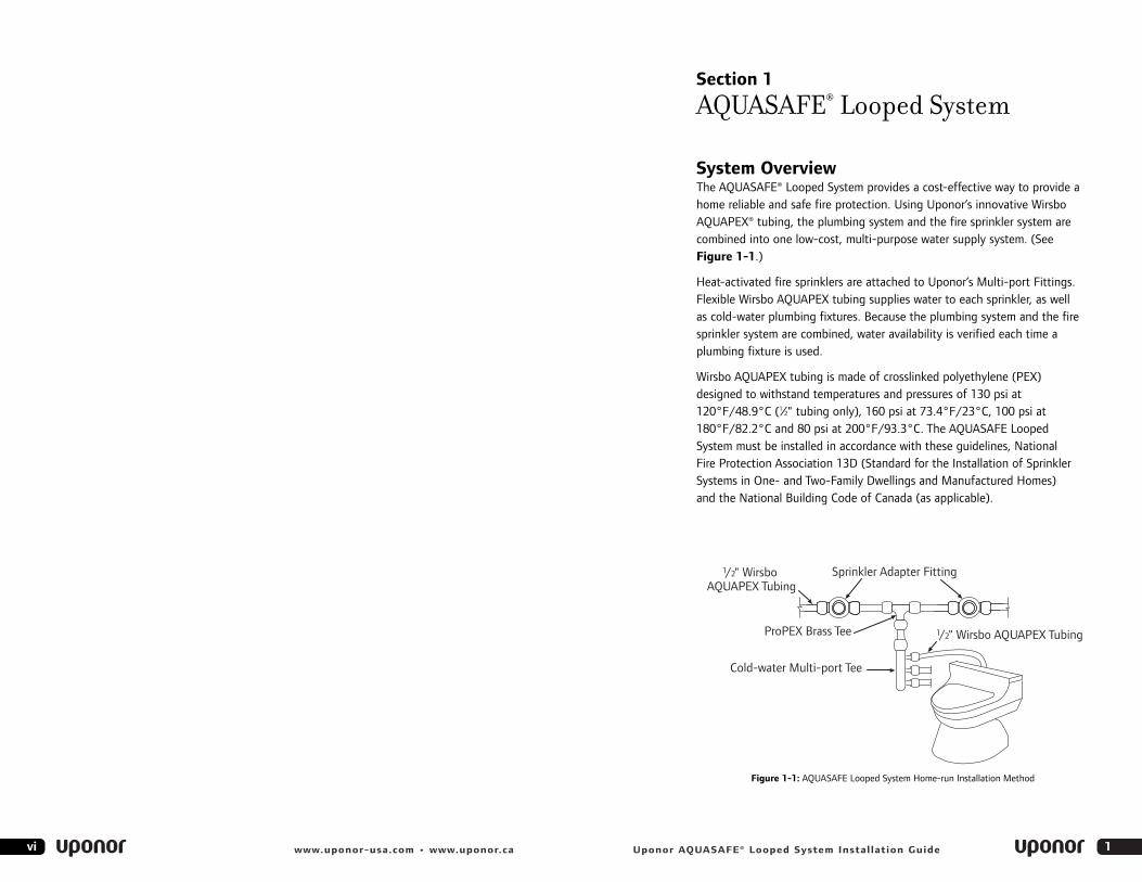
System OverviewThe AQUASAFE® Looped System provides a cost-effective way to provide ahome reliable and safe fire protection. Using Uponor’s innovative WirsboAQUAPEX® tubing, the plumbing system and the fire sprinkler system arecombined into one low-cost, multi-purpose water supply system. (SeeFigure 1-1.)
Heat-activated fire sprinklers are attached to Uponor’s Multi-port Fittings.Flexible Wirsbo AQUAPEX tubing supplies water to each sprinkler, as well as cold-water plumbing fixtures. Because the plumbing system and the firesprinkler system are combined, water availability is verified each time aplumbing fixture is used.
Wirsbo AQUAPEX tubing is made of crosslinked polyethylene (PEX)designed to withstand temperatures and pressures of 130 psi at120°F/48.9°C (1⁄2" tubing only), 160 psi at 73.4°F/23°C, 100 psi at180°F/82.2°C and 80 psi at 200°F/93.3°C. The AQUASAFE Looped System must be installed in accordance with these guidelines, National Fire Protection Association 13D (Standard for the Installation of SprinklerSystems in One- and Two-Family Dwellings and Manufactured Homes) and the National Building Code of Canada (as applicable).
1vi www.uponor-usa.com • www.uponor.ca Uponor AQUASAFE® Looped System Installation Guide
Figure 1-1: AQUASAFE Looped System Home-run Installation Method
Cold-water Multi-port Tee
1/2" WirsboAQUAPEX Tubing
1/2" Wirsbo AQUAPEX Tubing
Sprinkler Adapter Fitting
ProPEX Brass Tee
• Wirsbo AQUAPEX tubing is listed to NSF International Standard 14, which defines requirements for ingredients, materials, products, qualityassurance and marking.
• Wirsbo AQUAPEX tubing and the Uponor sprinkler assembly are listed to NSF International Standard 61, which defines requirements for toxicity.
• Wirsbo AQUAPEX tubing and fittings are certified to be in compliancewith the Canadian Standards Association Standard CAN/CSA B137.5M,“Crosslinked Polyethylene (PEX) Tubing Systems for Pressure Applications.”
• Wirsbo AQUAPEX tubing is UL-listed in accordance with UL 1821, and C-UL-listed in accordance with ULC/ORD C199P.
Model Code Approvals, Material Standards and Certifications for Wirsbo AQUAPEX Tubingand Fittings• UL • NSF • UPC • C-UL • CSA • IPC
Note: Due to limited space on the fittings, affected Uponor fittings carry the following UL and C-UL designation: . Please see UL’s website, www.ul.com/database, for UL documentation for the Uponor system.
UL and C-UL Listing Requirements and Handling GuidelinesAlthough not comprehensive, the following highlights the most commonguidelines and listing requirements when handling Uponor tubing andUponor fire safety system components:
• Install Uponor systems according to the manufacturer’s installationinstructions. Failure to follow the instructions and installation guidelinesin the installation guide can result in the failure of Uponor systems.
• Do not store sprinkler assemblies or cover plates in areas subject toextreme temperatures (over 100°F/37.7°C).
• Do not use Uponor PEX where temperatures and pressures exceed ratings. Uponor PEX used in Uponor fire safety systems must not exceed 130 psi at 120°F/48.9°C.
• Ensure the ambient temperature where Uponor PEX is installed does not exceed 120°F/48.9°C.
• In accordance with the UL and C-UL-listings, do not use or store Wirsbo AQUAPEX tubing where it will be exposed to direct sunlight for more than 15 days.
3
Using a stainless-steel Multi-port Fitting with ProPEX® outlets, individuallines from cold-water ProPEX manifolds supply water to the residential fire sprinklers, as well as cold-water fixtures. Hot-water ProPEX manifoldssupply hot water directly to necessary plumbing fixtures throughout thehouse in a separate system.
System Features and Benefits• 25-year warranty on Wirsbo AQUAPEX tubing when
used with ProPEX fittings*• 25-year warranty on ProPEX fittings and Uponor Multi-port
fittings when used with Wirsbo AQUAPEX tubing**• Easily integrates into the plumbing system• Improves water pressure at all fixtures• Quickly installed using ProPEX fitting connections• System verifies fresh water is available to the sprinklers each
time an occupant uses a cold-water plumbing fixture
* When installed by an Uponor-trained, licensed contractor
** When used with Wirsbo AQUAPEX tubing
Material Standards, Ratings and Certifications • Wirsbo AQUAPEX tubing and fittings are Underwriters Laboratories (UL)
and Canadian Underwriters Laboratories (C-UL) listed for use in multi-purpose piping systems of residential occupancies as defined in theStandard for Installation of Sprinkler Systems in One- and Two-familyDwellings and Manufactured Homes, NFPA 13D. Uponor’s UL listing wasissued in June 2000.
• Wirsbo AQUAPEX tubing is manufactured to ASTM F876, ASTM F877,ASTM F1960 and ASTM F2023 as certified by NSF International.
• Wirsbo AQUAPEX tubing carries the following maximum pressure andtemperature ratings:- 80 psi at 200°F/93.3°C- 100 psi at 180°F/82.2°C- 130 psi at 120°F/48.9°C (1⁄2" tubing only, in accordance with UL 1821
and ULC/ORD C199P)- 160 psi at 73.4°F/23°C
• The tubing and fittings are intended for use in multi-purpose systems not equipped with a fire department connection and having a workingpressure not greater than 130 psi.
• The tubing and fittings are intended for use in areas where the maximumambient temperature does not exceed 120°F/48.9°C.
• Wirsbo AQUAPEX tubing carries a standard grade rating recommended by the Plastics Pipe Institute (PPI).
2 Uponor AQUASAFE® Looped System Installation Guidewww.uponor-usa.com • www.uponor.ca
Necessary Parts and ToolsIn addition to Uponor parts, use the following tools for the installation:
• Two 1⁄2" right-angle drills
• Two 3⁄4" electrician drill bits
• #10 x 11⁄4" coarse thread screws (or similar fasteners) and washer
• Two 3⁄8" cordless drills (90-degree drills work best)
• Ladders
• Hammers
• Teflon® tape
Tubing Identification The labeling (print line) on Wirsbo AQUAPEX tubing reads as follows:WIRSBO AQUAPEX® PEX 1006 1⁄2IN SDR9/ B137.5 POTABLE /130PSI 120°F UL1821/ULC-ORD C199P( ASTM F876/F877/F2023)(ASTM F1960/F1807/F2098/F2080) /ICCSR-1099/ ICBO ES ER4407/HUD MR1269b(WHI-LISTED CAN/US FS25/SD50)/160PSI 73.4°F/100PSI180°F/80PSI 200°F WIRSBO-PEX-a TUBING *UN04950127 **xxxxxx
*USA, Material Type, Extruder No., Year, Month, Day**Footage marking in increments of three
System Design ProgramAll Uponor fire safety systems are designed using custom design software. Uponor designers use the program to create systems that providereliable fire sprinkler protection. The program specifies the proper locationfor sprinklers, as well as necessary flow rates. The program is designed tocomply with national fire codes and standards and meets the requirementsof NFPA 13D Standard and the National Building Code of Canada (asapplicable). For more information about Uponor’s design capabilities,contact your local manufacturer representative.
Note: Uponor supplies all fire safety system designs.
5
Handling Guidelines, (cont.)• Do not weld, glue or use adhesives or adhesive tape with
Wirsbo AQUAPEX tubing.
• Do not apply open flame to Wirsbo AQUAPEX tubing.
• Do not install Wirsbo AQUAPEX tubing within six inches of any gas appliance vents, with the exception of B vents.
• Do not install Wirsbo AQUAPEX tubing within 12 inches of any recessedlight fixtures, unless the PEX line is insulated.
• Do not solder within 18 inches of Wirsbo AQUAPEX tubing in the same water line. Make sweat connections prior to making the ProPEX connection.
• Do not use Wirsbo AQUAPEX tubing to convey natural gas.
• Do not use Wirsbo AQUAPEX tubing for an electrical ground.
• Do not spray on or allow organic chemicals, strong acids or strong basesto come into contact with Wirsbo AQUAPEX tubing. Verify firestop compatibility with firestop manufacturing.
• Do not install tubing or fitting outdoors.
• Do not use petroleum or solvent-based paints on Wirsbo AQUAPEX tubing.
• Use only approved and appropriate firestop materials with WirsboAQUAPEX tubing. Verify firestop compatibility with the firestop manufacturer.
• Do not allow rodents, insects or other pests to come into contact with Uponor PEX tubing.
• Do not subject Wirsbo AQUAPEX tubing to impact.
• Do not install Wirsbo AQUAPEX tubing in plenums or within 24 inches of air return grills or other openings in the ceiling.
• During remodeling or ceiling repair, implement appropriate precautions to protect the tubing and sprinklers from damage.
• Wirsbo AQUAPEX tubing and ProPEX fittings are intended for use in hydronic pipe systems only.
4 Uponor AQUASAFE® Looped System Installation Guidewww.uponor-usa.com • www.uponor.ca
Section 2
Working With Wirsbo AQUAPEX Tubing
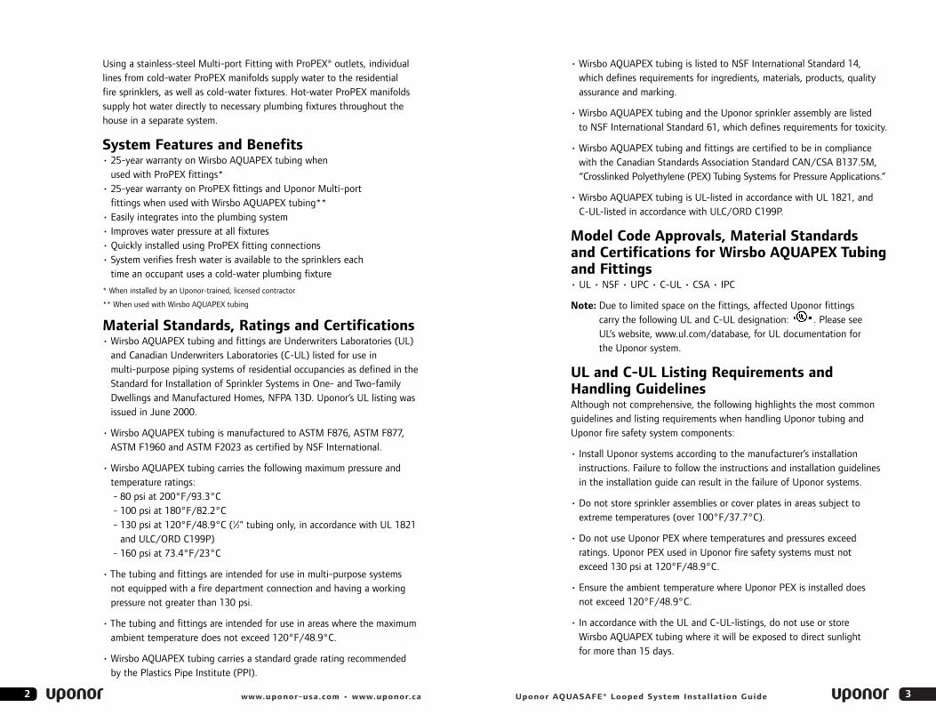
Wirsbo AQUAPEX tubing is a workable and installation-friendly construction material. Its flexibility eliminates many of the joints necessarywith a rigid piping system. The following procedures are recommended tosimplify installation:
Reforming Kinked TubingIf the tubing kinks and hinders flow, repairs can be made easily by performing the following:
1. Straighten the kinked portion of the tubing.
2. Heat the kinked area to approximately 265°F/129.4°C with an electricheat gun (approximately 450 watts of power). Apply the heat evenly until the tubing returns to its original size and shape. Do not use an open flame.
Caution: Heat the Wirsbo AQUAPEX tubing just long enough to remove the kink. Remove the heat source from the tubing as soon as possible; excessive heat may harm the outer polyethylene layer. Damage to the outer layer is only aesthetic; it does not affect the performance of the tubing.
3. Let the repaired Wirsbo AQUAPEX tubing cool undisturbed to room temperature. When the tubing returns to its original appearance, the repair is complete.
Caution: The tubing’s surface temperature must not exceed 338°F/170°C. Do not apply direct flame to Wirsbo AQUAPEX tubing.
Wirsbo AQUAPEX tubing repaired according to these recommendations will return to its original shape and strength. If Wirsbo AQUAPEX tubing is sliced, punctured or otherwise damaged beyond the capacity of thecrosslinked memory, it is necessary to remove and replace the entiresection. PEX cannot be welded or repaired with adhesives.
Caution: When reforming kinked tubing, protect sprinklers and cover plates from excessive heat. These devices are heatsensitive. Excessive temperatures may cause the sprinkler’s glassbulb to burst, activating discharge.
7Uponor AQUASAFE® Looped System Installation Guide6 www.uponor-usa.com • www.uponor.ca
Uponor CompactSelect Uncoiler
Section 3
Sprinkler Options
Only National Sanitation Foundation (NSF)-listed residential fire sprinklersare compatible with the AQUASAFE Looped System.
Note: Ensure all sprinklers are installed within their listing limitations.Additionally, ensure that the Uponor sprinkler cabinet that remains in the home contains sprinklers identical to those installed in the system.
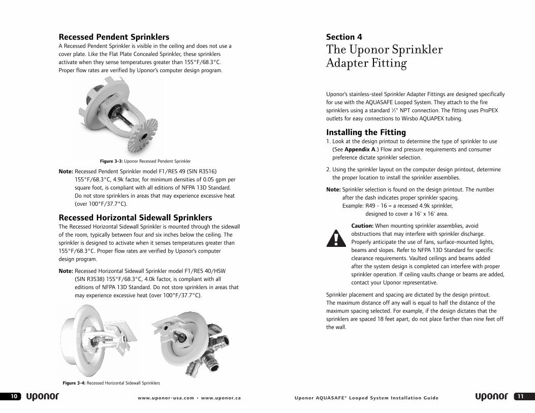
Concealed SprinklersThe Concealed Sprinkler is not visible in theceiling because it is covered by a special plate.This plate drops away from the sprinkler at135°F/57.2°C. The sprinkler is designed toactivate when it senses temperatures greaterthan 165°F/73.9°C. Proper flow rates areverified by Uponor’s computer design program.
Caution: Do not paint cover plates. Paint coverage may interfere with theheat sensitivity of the sprinkler.Custom-painted cover plates areavailable from Uponor. Contact your arearepresentative for information.
Note: Concealed Sprinkler modelRFC43 (SIN RA0612),165°F/73.9°C, 4.3k factor,for minimum densities of 0.05 gpm per square foot, is compliant with all editions of NFPA 13D Standard. Do not store sprinklers in areas that may experience excessive heat (over 100°F/37.3°C).
9Uponor AQUASAFE® Looped System Installation Guide
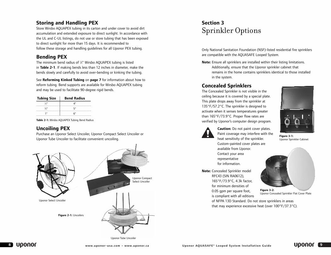
Storing and Handling PEXStore Wirsbo AQUAPEX tubing in its carton and under cover to avoid dirt accumulation and extended exposure to direct sunlight. In accordance withthe UL and C-UL listings, do not use or store tubing that has been exposedto direct sunlight for more than 15 days. It is recommended to follow these storage and handling guidelines for all Uponor PEX tubing.
Bending PEXThe minimum bend radius of 1⁄2" Wirsbo AQUAPEX tubing is listed in Table 2-1. If making bends less than 12 inches in diameter, make thebends slowly and carefully to avoid over-bending or kinking the tubing.
See Reforming Kinked Tubing on page 7 for information about how toreform tubing. Bend supports are available for Wirsbo AQUAPEX tubing and may be used to facilitate 90-degree rigid bends.
Uncoiling PEXPurchase an Uponor Select Uncoiler, Uponor Compact Select Uncoiler orUponor Tube Uncoiler to facilitate convenient uncoiling.
8 www.uponor-usa.com • www.uponor.ca
Uponor Select Uncoiler
Tubing Size Bend Radius1⁄2" 4"3⁄4" 5"
1" 6"
Table 2-1: Wirsbo AQUAPEX Tubing Bend Radius
Uponor Tube Uncoiler
Figure 2-1: Uncoilers
Figure 3-1:Uponor Sprinkler Cabinet
Figure 3-2:Uponor Concealed Sprinkler Flat Cover Plate
Section 4
The Uponor Sprinkler Adapter Fitting
Uponor’s stainless-steel Sprinkler Adapter Fittings are designed specificallyfor use with the AQUASAFE Looped System. They attach to the firesprinklers using a standard 1⁄2" NPT connection. The fitting uses ProPEXoutlets for easy connections to Wirsbo AQUAPEX tubing.
Installing the Fitting1. Look at the design printout to determine the type of sprinkler to use
(See Appendix A.) Flow and pressure requirements and consumer preference dictate sprinkler selection.
2. Using the sprinkler layout on the computer design printout, determinethe proper location to install the sprinkler assemblies.
Note: Sprinkler selection is found on the design printout. The number after the dash indicates proper sprinkler spacing. Example: R49 - 16 = a recessed 4.9k sprinkler,
designed to cover a 16' x 16' area.
Caution: When mounting sprinkler assemblies, avoid obstructions that may interfere with sprinkler discharge. Properly anticipate the use of fans, surface-mounted lights,beams and slopes. Refer to NFPA 13D Standard for specificclearance requirements. Vaulted ceilings and beams added after the system design is completed can interfere with propersprinkler operation. If ceiling vaults change or beams are added,contact your Uponor representative.
Sprinkler placement and spacing are dictated by the design printout. The maximum distance off any wall is equal to half the distance of themaximum spacing selected. For example, if the design dictates that thesprinklers are spaced 18 feet apart, do not place farther than nine feet offthe wall.
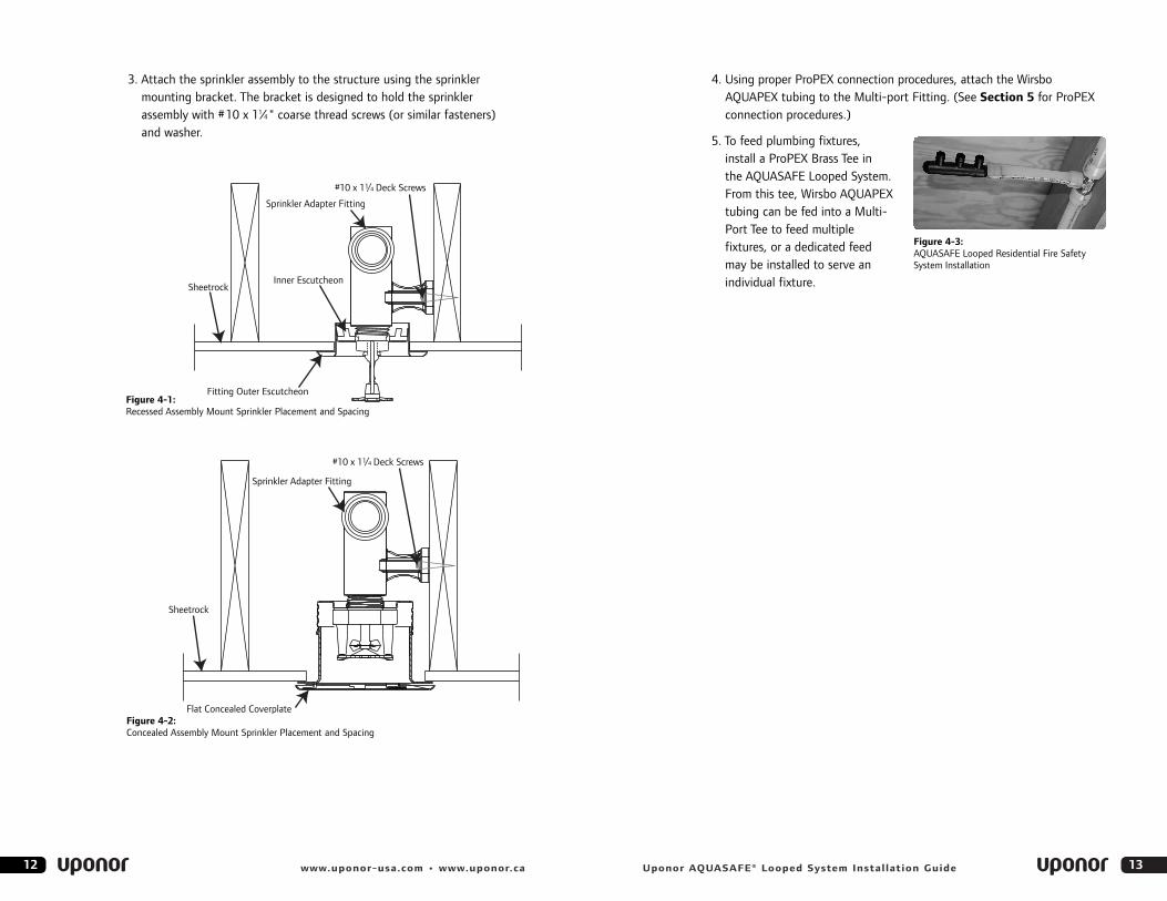
Recessed Pendent SprinklersA Recessed Pendent Sprinkler is visible in the ceiling and does not use acover plate. Like the Flat Plate Concealed Sprinkler, these sprinklersactivate when they sense temperatures greater than 155°F/68.3°C. Proper flow rates are verified by Uponor’s computer design program.
Note: Recessed Pendent Sprinkler model F1/RES 49 (SIN R3516)155°F/68.3°C, 4.9k factor, for minimum densities of 0.05 gpm persquare foot, is compliant with all editions of NFPA 13D Standard. Do not store sprinklers in areas that may experience excessive heat(over 100°F/37.7°C).
Recessed Horizontal Sidewall SprinklersThe Recessed Horizontal Sidewall Sprinkler is mounted through the sidewallof the room, typically between four and six inches below the ceiling. Thesprinkler is designed to activate when it senses temperatures greater than155°F/68.3°C. Proper flow rates are verified by Uponor’s computer design program.
Note: Recessed Horizontal Sidewall Sprinkler model F1/RES 40/HSW (SIN R3538) 155°F/68.3°C, 4.0k factor, is compliant with alleditions of NFPA 13D Standard. Do not store sprinklers in areas thatmay experience excessive heat (over 100°F/37.7°C).
1110 www.uponor-usa.com • www.uponor.ca Uponor AQUASAFE® Looped System Installation Guide
Figure 3-3: Uponor Recessed Pendent Sprinkler
Figure 3-4: Recessed Horizontal Sidewall Sprinklers
4. Using proper ProPEX connection procedures, attach the Wirsbo AQUAPEX tubing to the Multi-port Fitting. (See Section 5 for ProPEXconnection procedures.)
5. To feed plumbing fixtures, install a ProPEX Brass Tee in the AQUASAFE Looped System. From this tee, Wirsbo AQUAPEXtubing can be fed into a Multi-Port Tee to feed multiple fixtures, or a dedicated feed may be installed to serve anindividual fixture.
13Uponor AQUASAFE® Looped System Installation Guide12 www.uponor-usa.com • www.uponor.ca
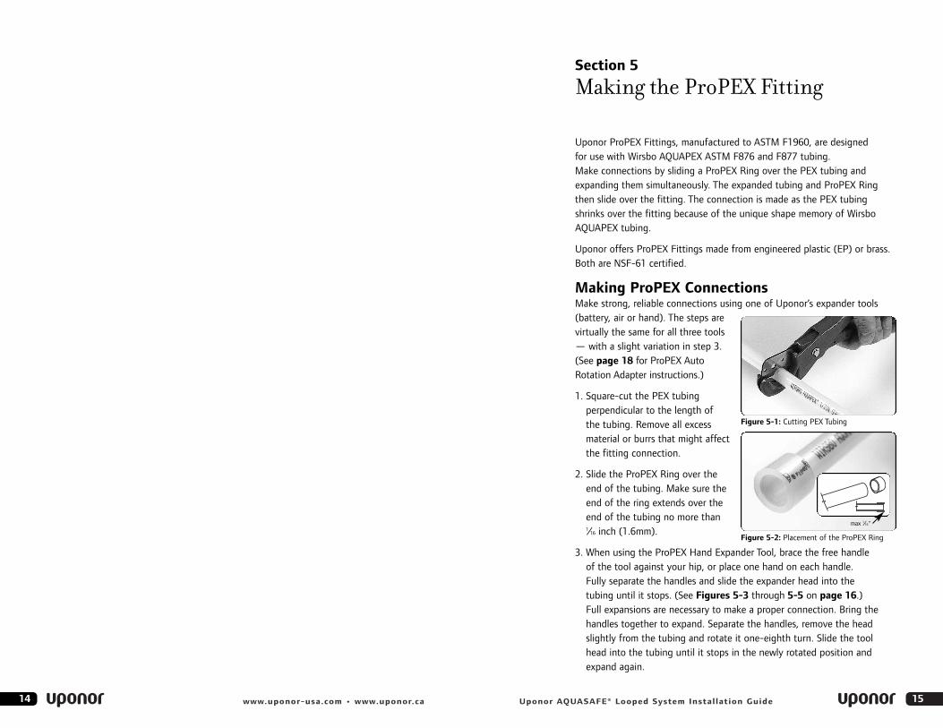
3. Attach the sprinkler assembly to the structure using the sprinkler mounting bracket. The bracket is designed to hold the sprinkler assembly with #10 x 11⁄4 " coarse thread screws (or similar fasteners) and washer.
#10 x 11/4 Deck Screws
Sprinkler Adapter Fitting
Flat Concealed Coverplate
Sheetrock
#10 x 11/4 Deck Screws
Sprinkler Adapter Fitting
Inner Escutcheon
Fitting Outer Escutcheon
Sheetrock
Figure 4-2:Concealed Assembly Mount Sprinkler Placement and Spacing
Figure 4-1:Recessed Assembly Mount Sprinkler Placement and Spacing
Figure 4-3:AQUASAFE Looped Residential Fire SafetySystem Installation
14 www.uponor-usa.com • www.uponor.ca
Section 5
Making the ProPEX Fitting
Uponor ProPEX Fittings, manufactured to ASTM F1960, are designed for use with Wirsbo AQUAPEX ASTM F876 and F877 tubing. Make connections by sliding a ProPEX Ring over the PEX tubing andexpanding them simultaneously. The expanded tubing and ProPEX Ringthen slide over the fitting. The connection is made as the PEX tubingshrinks over the fitting because of the unique shape memory of WirsboAQUAPEX tubing.
Uponor offers ProPEX Fittings made from engineered plastic (EP) or brass.Both are NSF-61 certified.
Making ProPEX ConnectionsMake strong, reliable connections using one of Uponor’s expander tools(battery, air or hand). The steps arevirtually the same for all three tools— with a slight variation in step 3.(See page 18 for ProPEX AutoRotation Adapter instructions.)
1. Square-cut the PEX tubing perpendicular to the length of the tubing. Remove all excessmaterial or burrs that might affectthe fitting connection.
2. Slide the ProPEX Ring over theend of the tubing. Make sure theend of the ring extends over theend of the tubing no more than 1⁄16 inch (1.6mm).
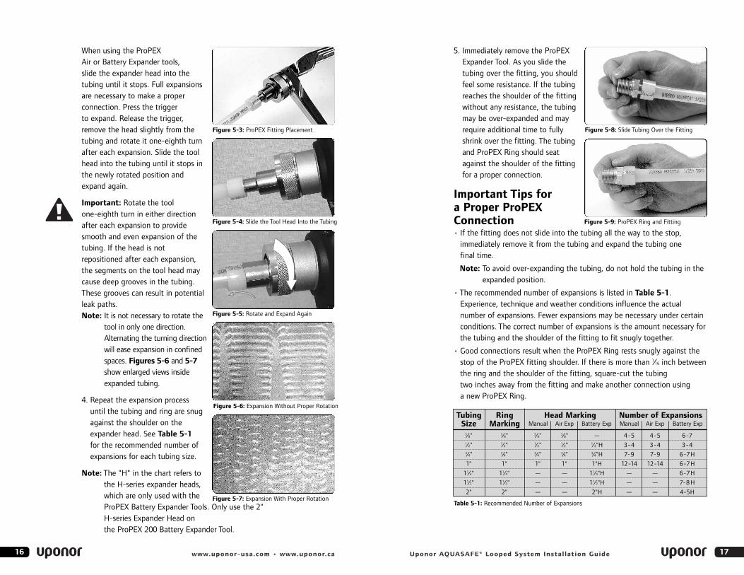
3. When using the ProPEX Hand Expander Tool, brace the free handle of the tool against your hip, or place one hand on each handle. Fully separate the handles and slide the expander head into the tubing until it stops. (See Figures 5-3 through 5-5 on page 16.)Full expansions are necessary to make a proper connection. Bring thehandles together to expand. Separate the handles, remove the headslightly from the tubing and rotate it one-eighth turn. Slide the toolhead into the tubing until it stops in the newly rotated position andexpand again.
15Uponor AQUASAFE® Looped System Installation Guide
max 1⁄16"
Figure 5-1: Cutting PEX Tubing
Figure 5-2: Placement of the ProPEX Ring
5. Immediately remove the ProPEXExpander Tool. As you slide the tubing over the fitting, you shouldfeel some resistance. If the tubingreaches the shoulder of the fittingwithout any resistance, the tubingmay be over-expanded and mayrequire additional time to fully shrink over the fitting. The tubingand ProPEX Ring should seatagainst the shoulder of the fittingfor a proper connection.
Important Tips for a Proper ProPEXConnection• If the fitting does not slide into the tubing all the way to the stop,
immediately remove it from the tubing and expand the tubing one final time.
Note: To avoid over-expanding the tubing, do not hold the tubing in theexpanded position.
• The recommended number of expansions is listed in Table 5-1.Experience, technique and weather conditions influence the actualnumber of expansions. Fewer expansions may be necessary under certainconditions. The correct number of expansions is the amount necessary forthe tubing and the shoulder of the fitting to fit snugly together.
• Good connections result when the ProPEX Ring rests snugly against the stop of the ProPEX fitting shoulder. If there is more than 1⁄16 inch betweenthe ring and the shoulder of the fitting, square-cut the tubing two inches away from the fitting and make another connection using a new ProPEX Ring.
Table 5-1: Recommended Number of Expansions
17Uponor AQUASAFE® Looped System Installation Guide
When using the ProPEX Air or Battery Expander tools, slide the expander head into thetubing until it stops. Full expansionsare necessary to make a properconnection. Press the trigger to expand. Release the trigger,remove the head slightly from thetubing and rotate it one-eighth turnafter each expansion. Slide the toolhead into the tubing until it stops inthe newly rotated position andexpand again.
Important: Rotate the tool one-eighth turn in either directionafter each expansion to providesmooth and even expansion of thetubing. If the head is notrepositioned after each expansion,the segments on the tool head maycause deep grooves in the tubing.These grooves can result in potentialleak paths.Note: It is not necessary to rotate the
tool in only one direction.Alternating the turning directionwill ease expansion in confinedspaces. Figures 5-6 and 5-7show enlarged views insideexpanded tubing.
4. Repeat the expansion process until the tubing and ring are snugagainst the shoulder on theexpander head. See Table 5-1for the recommended number ofexpansions for each tubing size.
Note: The "H" in the chart refers tothe H-series expander heads,which are only used with theProPEX Battery Expander Tools. Only use the 2" H-series Expander Head on the ProPEX 200 Battery Expander Tool.
16 www.uponor-usa.com • www.uponor.ca
Tubing Ring Head Marking Number of ExpansionsSize Marking Manual Air Exp Battery Exp Manual Air Exp Battery Exp
3⁄8" 3⁄8" 3⁄8" 3⁄8" — 4-5 4-5 6-71⁄2" 1⁄2" 1⁄2" 1⁄2" 1⁄2"H 3-4 3-4 3-43⁄4" 3⁄4" 3⁄4" 3⁄4" 3⁄4"H 7-9 7-9 6-7H
1" 1" 1" 1" 1"H 12-14 12-14 6-7H
11⁄4" 11⁄4" — — 11⁄4"H — — 6-7H
11⁄2" 11⁄2" — — 11⁄2"H — — 7-8 H
2" 2" — — 2"H — — 4-5HFigure 5-7: Expansion With Proper Rotation
Figure 5-6: Expansion Without Proper Rotation
Figure 5-3: ProPEX Fitting Placement Figure 5-8: Slide Tubing Over the Fitting
Figure 5-9: ProPEX Ring and FittingFigure 5-4: Slide the Tool Head Into the Tubing
Figure 5-5: Rotate and Expand Again
Tubing Size
Ring Marking Manual Air Exp Bat Exp
3⁄8" 3⁄8" 4-5 4-5 4-51⁄2" 1⁄2" 3-4 3-4 3-45⁄8" 5⁄8" 6-7 6-7 6-73⁄4" 3⁄4" 7-9 7-9 7-91" 1" 12-14 12-14 12-14
Number of Expansions
Making 3⁄8" ProPEX ConnectionsThe 3⁄8" ProPEX Ring is smaller and thicker than the ProPEX Rings used forother tubing sizes. The 3⁄8" ProPEX Ring must be expanded once on eachside to properly fit over the tubing. Expansion of the ProPEX Ring is only necessary for 3⁄8" Wirsbo AQUAPEX® tubing.
1. Square-cut the 3⁄8" Wirsbo AQUAPEX tubing perpendicular to the length of the tubing.
2. Expand each side of 3⁄8" ProPEX Ring with the ProPEX® Expander Tool once.
3. Slide the expanded 3⁄8" ring over the end of the tubing. Make sure theend of the ring extends over the end of the tubing no more than 1⁄16 inch(1.6mm). Once the 3⁄8" ProPEX Ring is properly expanded on the tubing,refer to Steps 3 to 5 (pages 15 to 17) for further instruction.
4. When the temperature is above 40ºF/4.4ºC, ProPEX connections to 3⁄8" Wirsbo AQUAPEX tubing require four to five expansions. When thetemperature is below 40ºF/4.4ºC, only four expansions are necessary.
5. The thicker ProPEX Ring used for 3⁄8" ProPEX connections shrinks over the fitting faster than other size rings.
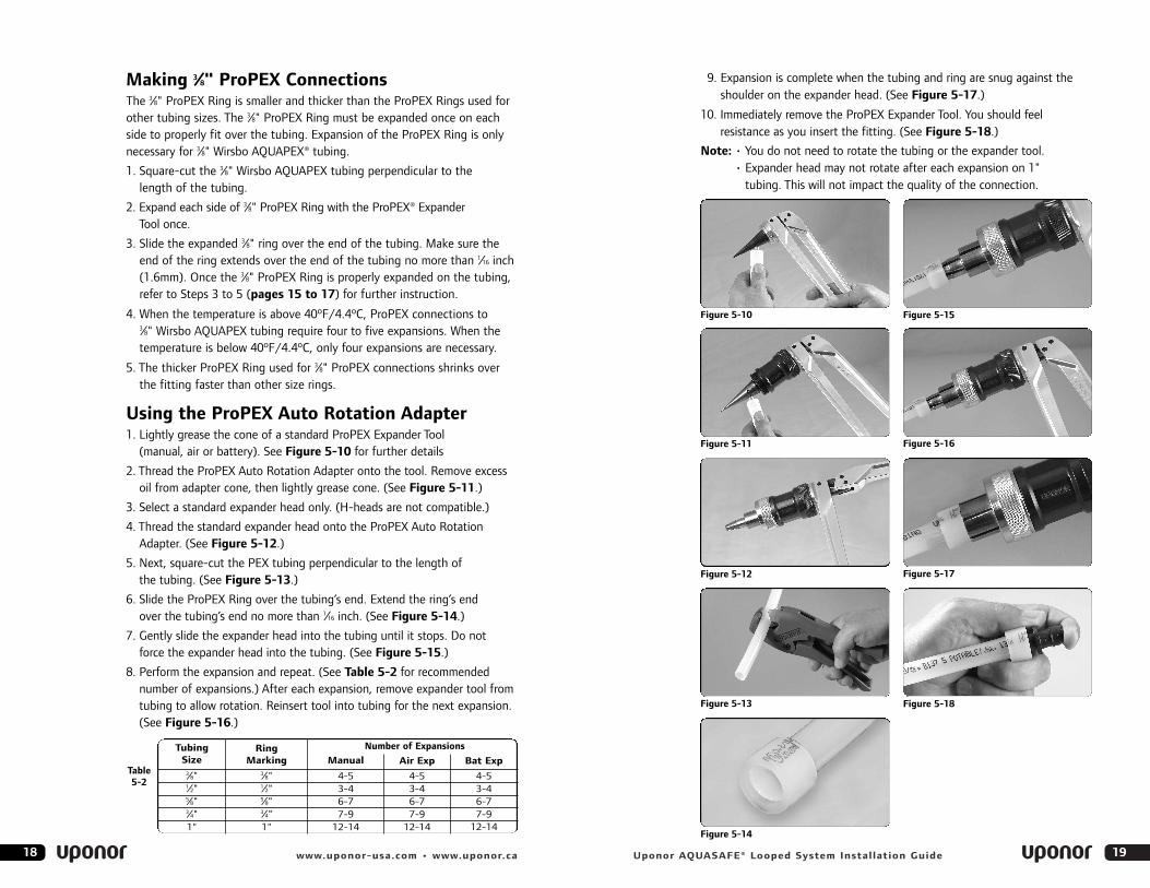
Using the ProPEX Auto Rotation Adapter1. Lightly grease the cone of a standard ProPEX Expander Tool
(manual, air or battery). See Figure 5-10 for further details
2. Thread the ProPEX Auto Rotation Adapter onto the tool. Remove excessoil from adapter cone, then lightly grease cone. (See Figure 5-11.)
3. Select a standard expander head only. (H-heads are not compatible.)
4. Thread the standard expander head onto the ProPEX Auto RotationAdapter. (See Figure 5-12.)
5. Next, square-cut the PEX tubing perpendicular to the length ofthe tubing. (See Figure 5-13.)
6. Slide the ProPEX Ring over the tubing’s end. Extend the ring’s end over the tubing’s end no more than 1⁄16 inch. (See Figure 5-14.)
7. Gently slide the expander head into the tubing until it stops. Do not force the expander head into the tubing. (See Figure 5-15.)
8. Perform the expansion and repeat. (See Table 5-2 for recommendednumber of expansions.) After each expansion, remove expander tool fromtubing to allow rotation. Reinsert tool into tubing for the next expansion. (See Figure 5-16.)
1918 www.uponor-usa.com • www.uponor.ca Uponor AQUASAFE® Looped System Installation Guide
Figure 5-10 Figure 5-15
Figure 5-11 Figure 5-16
Figure 5-12
Table 5-2
Figure 5-17
Figure 5-13
Figure 5-14
Figure 5-18
9. Expansion is complete when the tubing and ring are snug against theshoulder on the expander head. (See Figure 5-17.)
10. Immediately remove the ProPEX Expander Tool. You should feel resistance as you insert the fitting. (See Figure 5-18.)
Note: • You do not need to rotate the tubing or the expander tool.• Expander head may not rotate after each expansion on 1"
tubing. This will not impact the quality of the connection.
21Uponor AQUASAFE® Looped System Installation Guide20 www.uponor-usa.com • www.uponor.ca
Disconnecting a ProPEX Brass FittingProPEX Brass Fittings are manufactured connections and can be concealedin walls, ceilings and floors. However, when necessary, ProPEX BrassFittings can be disconnected. (EP fittings cannot be reclaimed or reused.)
To Disconnect a ProPEX Brass Fitting:1. Make sure the system is not pressurized.
2. Use a heat gun to heat one side of the ProPEX Ring. When the ring isclear, use a utility knife to carefully cut through the ring. Care should be taken to cut only the ring and not the tubing. This will protect the fitting from being gouged by the knife. Remove the ProPEX Ring fromthe tubing with pliers or another tool to avoid touching the hot ring.
Note: Do not gouge the fitting when cutting the ProPEX Ring. Nicks andgouges in the fitting may result in leaks. If gouged, discard the fitting.
3. When the ProPEX Ring is removed, apply heat directly around the fitting and tubing connection. Gently work the tubing back and forthwhile pulling slightly away from the fitting until the tubing separatesfrom the fitting.
4. When the tubing is removed from the fitting, square-cut the tubing two inches (minimum) from the end of the tubing.
5. Use a new ProPEX Ring and follow the steps to make a new ProPEX connection.
Note: Allow the fitting to cool before attempting to make another connection.
Troubleshooting ProPEX ConnectionsTrouble-free ProPEX installations begin with a ProPEX Expander Tool that is maintained in proper working condition. If the tool’s conical or segmentfingers are damaged, it is very difficult to make a proper connection. Thefollowing troubleshooting suggestions are designed to assist with problemsin the field.
For Fittings That Will Not Seal:• Make sure the expander head is securely screwed onto the tool
(hand-tightened).
• Make sure the expander head segment fingers are not bent. If the headdoes not completely close when the battery tool’s drive unit is fullyretracted or the handles of the manual tool are open, replace the head.
• Examine the tool for excess grease on the conical or expander headsegment fingers. Remove excess grease prior to making ProPEX connections.
• Examine the fitting for any damage. Sharp nicks and gouges on the fitting will cause the fitting to leak.
• Make sure the internal driver cone is not damaged or bent.
• Make sure the last expansion is not held in the expanded position before the fitting is inserted. The longer the tubing and ProPEX Ring are held in the expanded position, the greater the chance for a leak (due to over-expansion).
• Be sure to rotate the tool one-eighth turn after each expansion.
If Expansion is Difficult:• Make sure the internal cone is properly greased.
If the Expansion Head Slips out of the Tubing When Making Expansions:• Ensure the tubing and ProPEX Ring are dry.
• Make sure that grease is not getting into the tubing.
• Examine the expander head segment fingers to make sure that none are bent.
If the ProPEX Ring Slides Down the Tubing During Expansion:• Ensure your hands are clean while handling the tubing. Any sweat or
oils on your hands can act as a lubricant. Due to the smoothness of PEX,any form of lubricant can cause the ProPEX Ring to slide across thetubing during expansion.
• If you anticipate the ring may possibly slide down, position the ProPEX Ring slightly farther over the end of the tubing and make thefirst couple of expansions slowly. Once the ring and the tubing begin to expand together, you can continue with the normal number and typeof expansions.
• Place your thumb against the ProPEX Ring to help support it and feel forany movement. If caught early, you can slide the ring up the tubing andexpand as described in the previous bullet point.
Caution: Excessive lubrication may result in improperconnections. Only use a small amount of lubrication to keep the tool working properly.
• Once a month, soak the heads in degreasing agent to remove any greasefrom between the segments. Clean the cone using a clean dry cloth.
• Store the tool and expander heads in the case. Store the tool with anexpansion head in place to protect the cone.
• Store the tool in a dry location to prevent rust.
Handling Guidelines for Engineered Plastic (EP) FittingsAlthough not comprehensive, the following highlights the most common EPfitting guidelines:
• Do not solder within 18 inches of any EP fittings in the same water line.Sweat connections must be made prior to making the ProPEX connection.
• Do not subject EP fittings to impact.
• Do not use adhesives or adhesive tape with Uponor EP fittings.1
• Do not expose EP fittings to open flame.
• Do not allow solder, flux, pipe dope, solvents or urethane foams to comein contact with EP fittings as immediate damage may result.
• Never pull or drag tubing by the installed EP fittings.
• Do not expose EP fittings to excessive bending loads (greater than 100 pounds).
• Do not use EP fittings where temperatures and pressures exceed ratings.
• Do not spray on or allow organic chemicals, strong acids or strong basesto come into contact with EP fittings.
• Do not use petroleum or solvent-based paints on EP fittings.
• Do not allow rodents, insects or other pests to come into contact with EP fittings.
Note: EP Fittings are not listed to UL 1821 and may not be installed intoportions of the AQUASAFE Looped System. EP fittings are permittedto be installed to facilitate connections to cold-water potableplumbing fixtures as described in Sections 1 and 4 of this guide.
1 You may temporarily affix adhesive tape to EP fittings during installation. However, to protect theintegrity of the system, the tape should not be permanent. Remove the tape and residual adhesiveafter completing the installation.
23Uponor AQUASAFE® Looped System Installation Guide22 www.uponor-usa.com • www.uponor.ca
If More Than the Recommended Number of Expansions are Needed to Make a Connection:• Make sure that the head is hand-tightened to the expander tool.
• Examine the expander head segment fingers to make sure that none are bent.
• Be sure to completely cycle the tool on each expansion (i.e., close the manual tool handle or release the battery expander tool trigger).
Cold-weather Expansions• Temperature affects the time required for the tubing and ring to
shrink onto the fitting. The colder the temperature, the slower the contraction time.
• Warming ProPEX fittings and ProPEX Rings reduces contraction time. Putfittings and rings in your pockets prior to installation to keep them warm.
• ProPEX connections must be made at temperatures above 5ºF/-15ºC.
• Fewer expansions are necessary in temperatures below 40ºF/4.4°C.
Proper Expander Tool and Head MaintenanceThe ProPEX Expander Tools are sturdy, but must be handled with care toprevent possible damage to the cone and the expander heads.
• Remove and clean the segment fingers as needed.
• Remove the segments from the attachment ring by pushing the segmentfinger down toward the opening in the ring. Once the first segment isremoved, the rest follow easily.
• Place the segments on a flat surface with the ridges facing up. The fingers should lay flat without any curve in the middle. If the segmentsare bent, replace the head immediately.
• To reassemble, replace the segment fingers one at a time to the attachment ring by sliding the grooved portion of the segment fingersover the spring in the attachment ring. The narrow end of the segmentfingers point away from the solid side of the attachment ring. Hold these segment fingers in place with your thumb as the remaining segment fingers are inserted.
• Once the expander head is cleaned and reassembled, use a lint-free cloth to apply a light coat of lubricant to the cone prior to making anyProPEX connections.
• Apply the lubricant daily if used regularly.
• Keep all other parts of the tool free from lubricant.
• The Hand Expander Tool handles will open and close smoothly if the toolis properly lubricated.
• Failure to properly lubricate the tool may result in improper connections.
2524 www.uponor-usa.com • www.uponor.ca
Section 6
Extreme TemperatureInstructions
Cold-weather Expansions• Cold temperatures affect the time it takes for the tubing and ProPEX
Ring to shrink onto the fitting. The colder the temperature, the slowerthe contraction time.
• Warming up ProPEX fittings and rings speed up contraction time. Puttingfittings and rings in your pockets prior to installation is a simple way tokeep them warm.
• In temperatures below 40°F/4.4°C, do not hold the tubing in the expanded position.
• Fewer expansions may be necessary in cold weather.
• The correct number of expansions is the number it takes to getthe tubing and the shoulder of the fitting snug against each other.
• Rotate the tool after each expansion.
Note: At colder temperatures (below 40°F/4.4°C), it will take longer forProPEX connections to seal under pressure. If air leaks are foundduring pressure tests in cold weather, use a heat gun to gently warmup connections all the way around the circumference of the tubingfor about 15 seconds so that the tubing becomes warm to the touch.Do not let the tubing get hot enough so that it damages the outerpolyethylene layer. Even in cold weather, a heat gun is normally not required.
Caution: When warming connections, protect sprinklers and cover plates from excessive heat. Temperatures greater than155°F/68.3°C will cause the sprinkler’s glass bulb to burst, activating discharge.
Uponor AQUASAFE® Looped System Installation Guide
27Uponor AQUASAFE® Looped System Installation Guide26 www.uponor-usa.com • www.uponor.ca
Section 7
Tubing Supports and Fittings
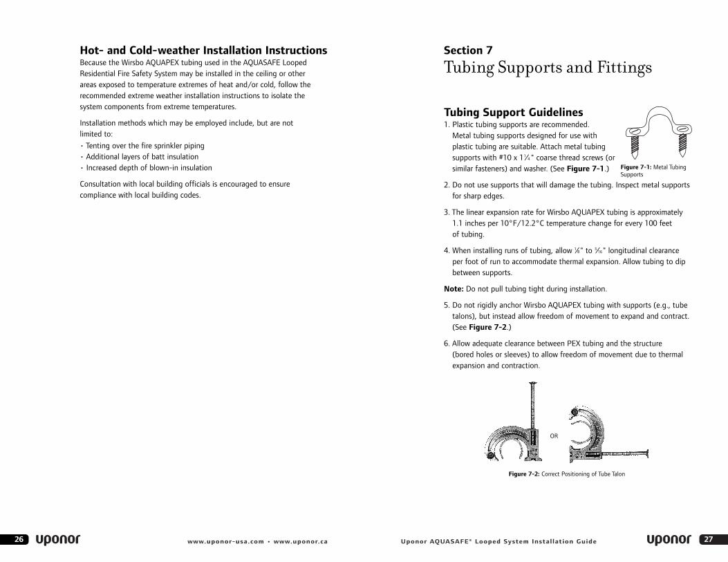
Tubing Support Guidelines1. Plastic tubing supports are recommended.
Metal tubing supports designed for use withplastic tubing are suitable. Attach metal tubingsupports with #10 x 11⁄4 " coarse thread screws (orsimilar fasteners) and washer. (See Figure 7-1.)
2. Do not use supports that will damage the tubing. Inspect metal supportsfor sharp edges.
3. The linear expansion rate for Wirsbo AQUAPEX tubing is approximately 1.1 inches per 10°F/12.2°C temperature change for every 100 feet of tubing.
4. When installing runs of tubing, allow 1⁄8" to 3⁄16" longitudinal clearanceper foot of run to accommodate thermal expansion. Allow tubing to dipbetween supports.
Note: Do not pull tubing tight during installation.
5. Do not rigidly anchor Wirsbo AQUAPEX tubing with supports (e.g., tubetalons), but instead allow freedom of movement to expand and contract.(See Figure 7-2.)
6. Allow adequate clearance between PEX tubing and the structure(bored holes or sleeves) to allow freedom of movement due to thermalexpansion and contraction.
Figure 7-2: Correct Positioning of Tube Talon
OR
Hot- and Cold-weather Installation InstructionsBecause the Wirsbo AQUAPEX tubing used in the AQUASAFE LoopedResidential Fire Safety System may be installed in the ceiling or other areas exposed to temperature extremes of heat and/or cold, follow the recommended extreme weather installation instructions to isolate the system components from extreme temperatures.
Installation methods which may be employed include, but are not limited to:
• Tenting over the fire sprinkler piping• Additional layers of batt insulation• Increased depth of blown-in insulation
Consultation with local building officials is encouraged to ensure compliance with local building codes.
Figure 7-1: Metal TubingSupports
2928 www.uponor-usa.com • www.uponor.ca Uponor AQUASAFE® Looped System Installation Guide
Note: In accordance with UL and C-UL listings, ensure protection is provided for the tubing and fittings. The minimum protection should consist of either:
• One layer of 3⁄8" (9.5mm) gypsum wallboard
• A suspended membrane ceiling with lay-in panels or tiles weighinggreater than 0.35 lbs. per square foot (1.7kg per square meter)when installed with metallic support grids
• 1⁄2" (13mm) plywood soffits
• One layer of 1⁄2" (13mm) plywood
Note: Do not rough-in the tubing and leave it exposed.
ProPEX FittingsPlease refer to the Uponor Product Catalog for a current listing of ProPEX Brass Couplings, Brass Elbows, Brass Tees, Brass Reducing Tees, Brass Male Threaded Adapters, Brass Female Threaded Adapters and BrassSweat Adapters.
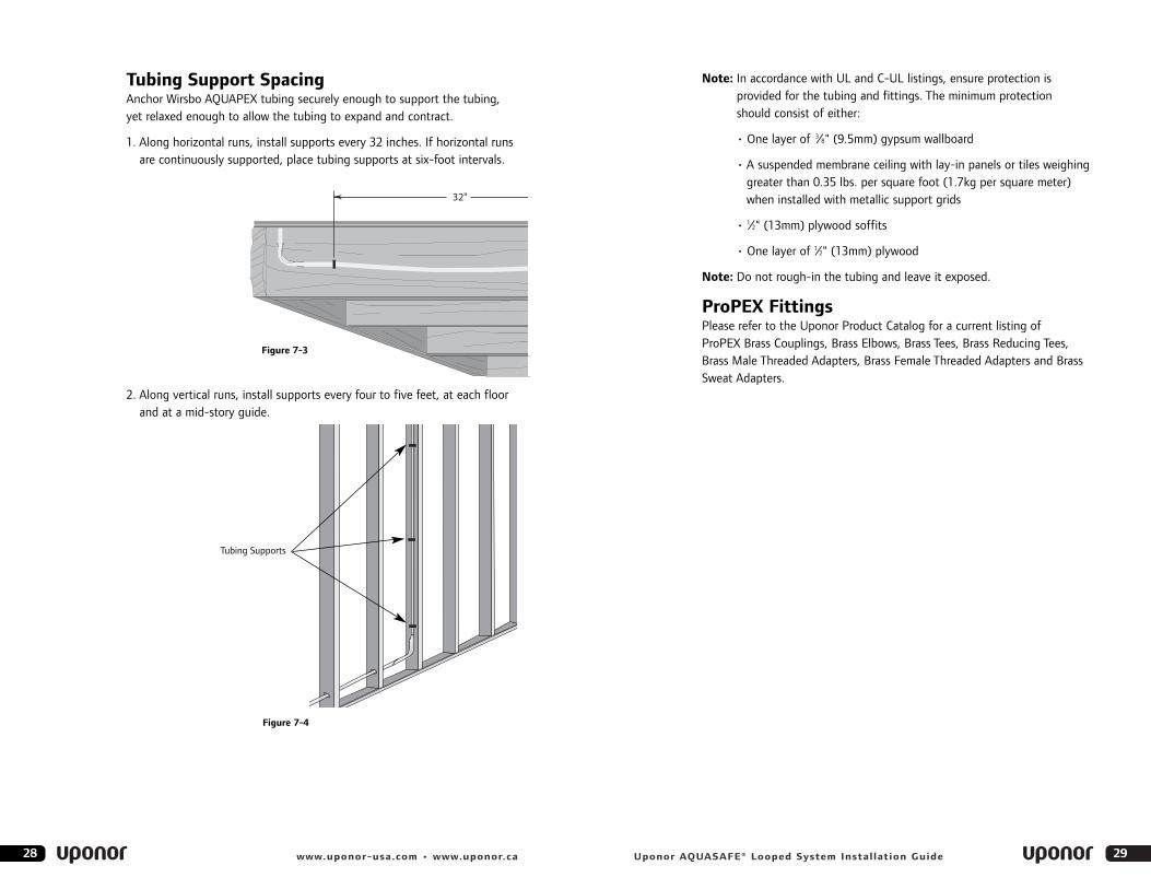
Tubing Support SpacingAnchor Wirsbo AQUAPEX tubing securely enough to support the tubing,yet relaxed enough to allow the tubing to expand and contract.
1. Along horizontal runs, install supports every 32 inches. If horizontal runsare continuously supported, place tubing supports at six-foot intervals.
2. Along vertical runs, install supports every four to five feet, at each floorand at a mid-story guide.
Tubing Supports
Figure 7-3
Figure 7-4
3130 www.uponor-usa.com • www.uponor.ca
Section 8
Pressure Testing
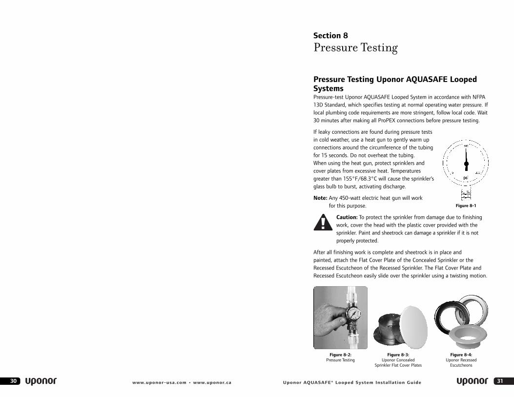
Pressure Testing Uponor AQUASAFE LoopedSystemsPressure-test Uponor AQUASAFE Looped System in accordance with NFPA13D Standard, which specifies testing at normal operating water pressure. Iflocal plumbing code requirements are more stringent, follow local code. Wait30 minutes after making all ProPEX connections before pressure testing.
If leaky connections are found during pressure tests in cold weather, use a heat gun to gently warm upconnections around the circumference of the tubingfor 15 seconds. Do not overheat the tubing. When using the heat gun, protect sprinklers andcover plates from excessive heat. Temperaturesgreater than 155°F/68.3°C will cause the sprinkler’sglass bulb to burst, activating discharge.
Note: Any 450-watt electric heat gun will work for this purpose.
Caution: To protect the sprinkler from damage due to finishingwork, cover the head with the plastic cover provided with thesprinkler. Paint and sheetrock can damage a sprinkler if it is notproperly protected.
After all finishing work is complete and sheetrock is in place and painted, attach the Flat Cover Plate of the Concealed Sprinkler or theRecessed Escutcheon of the Recessed Sprinkler. The Flat Cover Plate andRecessed Escutcheon easily slide over the sprinkler using a twisting motion.
Uponor AQUASAFE® Looped System Installation Guide
Figure 8-3: Uponor Concealed
Sprinkler Flat Cover Plates
Figure 8-4: Uponor Recessed
Escutcheons
Figure 8-2: Pressure Testing
Figure 8-1
33Uponor AQUASAFE® Looped System Installation Guide
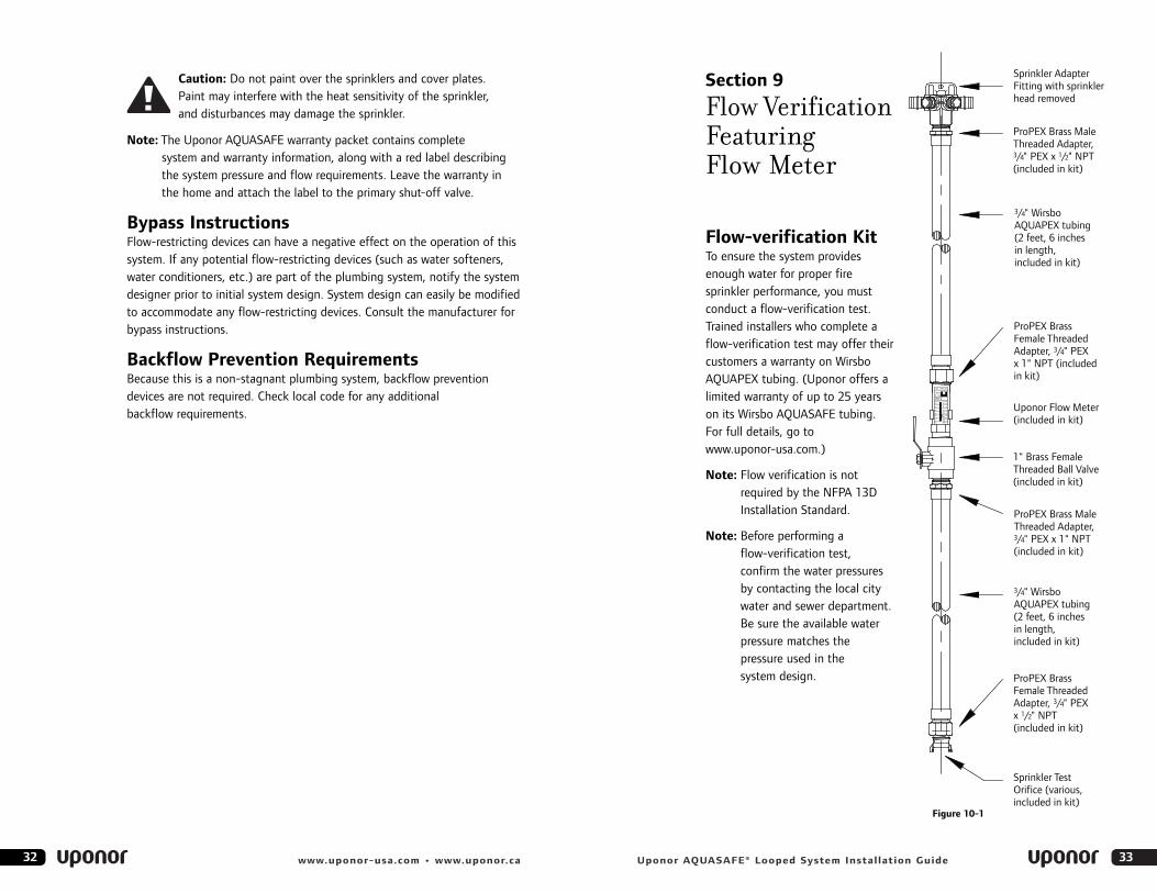
Section 9
Flow VerificationFeaturing Flow Meter
Flow-verification KitTo ensure the system provides enough water for proper fire sprinkler performance, you mustconduct a flow-verification test.Trained installers who complete aflow-verification test may offer theircustomers a warranty on WirsboAQUAPEX tubing. (Uponor offers alimited warranty of up to 25 yearson its Wirsbo AQUASAFE tubing.For full details, go towww.uponor-usa.com.)
Note: Flow verification is notrequired by the NFPA 13D Installation Standard.
Note: Before performing a flow-verification test, confirm the water pressuresby contacting the local citywater and sewer department.Be sure the available waterpressure matches thepressure used in thesystem design.
Sprinkler AdapterFitting with sprinklerhead removed
ProPEX Brass MaleThreaded Adapter,3/4" PEX x 1/2" NPT(included in kit)
3/4" WirsboAQUAPEX tubing(2 feet, 6 inchesin length,included in kit)
ProPEX BrassFemale ThreadedAdapter, 3/4" PEXx 1" NPT (includedin kit)
Uponor Flow Meter(included in kit)
1" Brass FemaleThreaded Ball Valve(included in kit)
ProPEX Brass MaleThreaded Adapter,3/4" PEX x 1" NPT(included in kit)
3/4" WirsboAQUAPEX tubing(2 feet, 6 inchesin length,included in kit)
ProPEX BrassFemale ThreadedAdapter, 3/4" PEXx 1/2" NPT(included in kit)
Sprinkler TestOrifice (various,included in kit)
250PSIMAX250F
WATERVKPF–100
GPM
242016128
4
0
Figure 10-1
32 www.uponor-usa.com • www.uponor.ca
Caution: Do not paint over the sprinklers and cover plates. Paint may interfere with the heat sensitivity of the sprinkler, and disturbances may damage the sprinkler.
Note: The Uponor AQUASAFE warranty packet contains completesystem and warranty information, along with a red label describingthe system pressure and flow requirements. Leave the warranty inthe home and attach the label to the primary shut-off valve.
Bypass InstructionsFlow-restricting devices can have a negative effect on the operation of thissystem. If any potential flow-restricting devices (such as water softeners,water conditioners, etc.) are part of the plumbing system, notify the systemdesigner prior to initial system design. System design can easily be modifiedto accommodate any flow-restricting devices. Consult the manufacturer forbypass instructions.
Backflow Prevention RequirementsBecause this is a non-stagnant plumbing system, backflow preventiondevices are not required. Check local code for any additional backflow requirements.
35Uponor AQUASAFE® Looped System Installation Guide34 www.uponor-usa.com • www.uponor.ca
9. Record the static pressure reading on the gauge near the manifold.
10. Open the valve until the plunger on the Flow Meter settles into position. This may take less than one minute. Using the markers on the Flow Meter, determine the flow through the test device. Record the residual pressure reading on the manifold gauge while the water is flowing.
11. Compare the results with the gallons per minute required on thesprinkler data sheet. Test results must equal or exceed required flow for proper operation and warranty coverage.
Note: If a two-sprinkler flow is required by the Authorities HavingJurisdiction (AHJ), two Flow Verification Kits are necessary.
12. Pull all Teflon® tape off detached sprinkler.
13. Apply new Teflon tape to the threads of the sprinkler (two to three wraps).
14. Screw the sprinkler back into the Multi-port Fitting using theappropriate sprinkler wrench. Approximately 10- to 25-foot pounds are required to secure the sprinkler in the fitting.
Note: The hydraulically most remote sprinkler or pair of sprinklers is indicated on the design printout in Appendix A. For testrequirements on other sprinklers, consult local code.
Note: It is a good idea to notify the fire inspector at least 24 hours prior toperforming a flow-verification test. This may speed up the inspectionprocess and eliminate the need to repeat the test for the inspector.
Troubleshooting Flow ProblemsIf the number of gallons that flow out of the sprinkler during a flow test isless than the number required by the manufacturer, check the following:
1. Verify the available water pressure.
2. Ensure the system is piped according to the design.
3. Verify that the proper test orifice was used for the flow test.
4. Check to see that all supply valves in the system are open.
5. Check to ensure that flow-restricting devices were not added after the design was complete.
6. Ensure that the water meter is sized in accordance with the drawing.
The Flow Verification Kit attaches to the Multi-port Fitting for proper flowmeasurement. The kit contains the following items:• Flow-control valve • Uponor Flow Meter• Four test orifices• 3⁄4" PEX x 1⁄2" FNPT• One 3⁄4" PEX x 1⁄2" MNPT• Two 3⁄4" PEX x 1" NPT
Performing a Flow-verification TestThe flow-verification test must be performed with all flow-restrictingdevices (water softener, etc.) in place.
1. Be sure the water is turned off. Carefully unscrew the sprinkler from the Multi-port Fitting. Place the sprinkler in a safe place to avoid any damage.
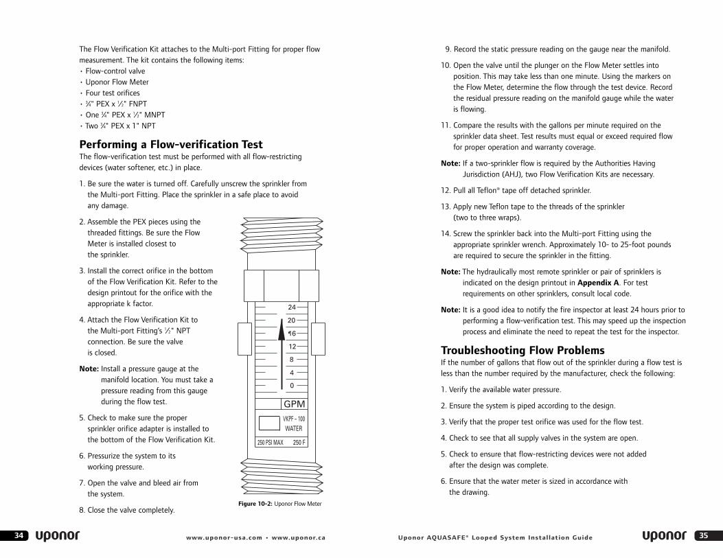
2. Assemble the PEX pieces using thethreaded fittings. Be sure the FlowMeter is installed closest tothe sprinkler.
3. Install the correct orifice in the bottomof the Flow Verification Kit. Refer to thedesign printout for the orifice with theappropriate k factor.
4. Attach the Flow Verification Kit tothe Multi-port Fitting’s 1⁄2" NPT connection. Be sure the valve is closed.
Note: Install a pressure gauge at themanifold location. You must take apressure reading from this gaugeduring the flow test.
5. Check to make sure the proper sprinkler orifice adapter is installed tothe bottom of the Flow Verification Kit.
6. Pressurize the system to its working pressure.
7. Open the valve and bleed air from the system.
8. Close the valve completely.
250 PSI MAX 250 F
WATER
0
4
8
12
16
20
24
GPM
VKPF – 100
Figure 10-2: Uponor Flow Meter
3736 www.uponor-usa.com • www.uponor.ca Uponor AQUASAFE® Looped System Installation Guide
Appendix A
The Uponor Design Printout
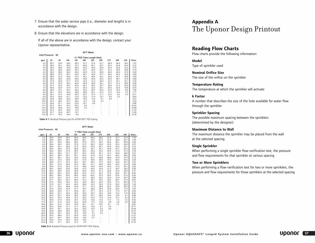
Reading Flow Charts Flow charts provide the following information:
ModelType of sprinkler used
Nominal Orifice SizeThe size of the orifice on the sprinkler
Temperature RatingThe temperature at which the sprinkler will activate
k FactorA number that describes the size of the hole available for water flowthrough the sprinkler
Sprinkler SpacingThe possible maximum spacing between the sprinklers (determined by the designer)
Maximum Distance to WallThe maximum distance the sprinkler may be placed from the wall at the selected spacing
Single SprinklerWhen performing a single sprinkler flow-verification test, the pressure and flow requirements for that sprinkler at various spacing
Two or More SprinklersWhen performing a flow-verification test for two or more sprinklers, thepressure and flow requirements for those sprinklers at the selected spacing
7. Ensure that the water service pipe (i.e., diameter and length) is in accordance with the design.
8. Ensure that the elevations are in accordance with the design.
If all of the above are in accordance with the design, contact yourUponor representative.
Inlet Pressure: 60
gpm 25 50 100 150 200 225 250 275 300 325 ft/sec
2.0 59.7 59.4 58.8 58.3 57.7 57.4 57.1 56.8 56.5 56.2 1.812.5 59.6 59.1 58.3 57.4 56.6 56.1 55.7 55.3 54.8 54.4 2.273.0 59.4 58.8 57.6 56.4 55.2 54.6 54.0 53.4 52.8 52.2 2.723.5 59.2 58.4 56.9 55.3 53.7 52.9 52.1 51.3 50.6 49.8 3.184.0 59.0 58.0 56.0 54.0 52.0 51.0 50.0 49.0 48.0 47.0 3.634.5 58.8 57.5 55.1 52.6 50.1 48.9 47.7 46.4 45.2 43.9 4.085.0 58.5 57.0 54.0 51.0 48.1 46.6 45.1 43.6 42.1 40.6 4.545.5 58.2 56.5 52.9 49.4 45.8 44.0 42.3 40.5 38.7 37.0 4.996.0 57.9 55.9 51.7 47.6 43.4 41.3 39.3 37.2 35.1 33.1 5.446.5 57.6 55.2 50.4 45.6 40.9 38.5 36.1 33.7 31.3 28.9 5.907.0 57.3 54.5 49.1 43.6 38.1 35.4 32.7 29.9 27.2 24.5 6.357.5 56.9 53.8 47.6 41.4 35.3 32.2 29.1 26.0 22.9 19.8 6.818.0 56.5 53.1 46.1 39.2 32.2 28.7 25.3 21.8 18.3 14.9 7.268.5 56.1 52.3 44.5 36.8 29.0 25.1 21.3 17.4 13.5 9.7 7.719.0 55.7 51.4 42.8 34.2 25.7 21.4 17.1 12.8 8.5 4.2 8.179.5 55.3 50.5 41.1 31.6 22.2 17.4 12.7 8.0 3.2 - 8.62
10.0 54.8 49.6 39.3 28.9 18.5 13.3 8.1 2.9 - - 9.0710.5 54.3 48.7 37.3 26.0 14.7 9.0 3.4 - - - 9.5311.0 53.8 47.7 35.4 23.0 10.7 4.6 - - - - 9.9811.5 53.3 46.7 33.3 20.0 6.6 - - - - - 10.4412.0 52.8 45.6 31.2 16.8 2.4 - - - - - 10.8912.5 52.2 44.5 29.0 13.5 - - - - - - 11.13.0 51.7 43.4 26.7 10.1 - - - - - - 11.13.5 51.1 42.2 24.4 6.6 - - - - - - 12.
3/4" PEX Tube Length (feet)
60oF Water
348025
Table 9-1: Residual Pressure (psi) for ASTM F877 PEX Tubing
Inlet Pressure: 60
gpm 25 50 100 150 200 250 275 300 325 350 ft/sec
3.0 59.8 59.6 59.3 58.9 58.6 58.2 58.0 57.8 57.7 57.5 1.653.5 59.8 59.5 59.1 58.6 58.1 57.6 57.4 57.2 56.9 56.7 1.924.0 59.7 59.4 58.8 58.2 57.6 57.0 56.7 56.4 56.1 55.8 2.204.5 59.6 59.3 58.5 57.8 57.0 56.3 55.9 55.5 55.2 54.8 2.475.0 59.6 59.1 58.2 57.3 56.4 55.5 55.1 54.6 54.2 53.7 2.755.5 59.5 58.9 57.9 56.8 55.7 54.7 54.1 53.6 53.1 52.5 3.026.0 59.4 58.8 57.5 56.3 55.0 53.8 53.2 52.5 51.9 51.3 3.306.5 59.3 58.6 57.1 55.7 54.2 52.8 52.1 51.4 50.6 49.9 3.577.0 59.2 58.4 56.7 55.1 53.4 51.8 51.0 50.1 49.3 48.5 3.857.5 59.1 58.1 56.3 54.4 52.6 50.7 49.8 48.8 47.9 47.0 4.128.0 59.0 57.9 55.8 53.7 51.6 49.6 48.5 47.5 46.4 45.4 4.408.5 58.8 57.7 55.3 53.0 50.7 48.4 47.2 46.0 44.9 43.7 4.679.0 58.7 57.4 54.8 52.3 49.7 47.1 45.8 44.5 43.2 41.9 4.959.5 58.6 57.2 54.3 51.5 48.6 45.8 44.4 42.9 41.5 40.1 5.22
10.0 58.4 56.9 53.8 50.6 47.5 44.4 42.8 41.3 39.7 38.2 5.5010.5 58.3 56.6 53.2 49.8 46.4 43.0 41.3 39.6 37.9 36.2 5.7711.0 58.2 56.3 52.6 48.9 45.2 41.5 39.7 37.8 36.0 34.1 6.0511.5 58.0 56.0 52.0 48.0 44.0 40.0 37.9 35.9 33.9 31.9 6.3212.0 57.8 55.7 51.3 47.0 42.7 38.4 36.2 34.0 31.9 29.7 6.6012.5 57.7 55.3 50.7 46.0 41.4 36.7 34.4 32.0 29.7 27.4 6.8713.0 57.5 55.0 50.0 45.0 40.0 35.0 32.5 30.0 27.5 25.0 7.1513.5 57.3 54.7 49.3 44.0 38.6 33.3 30.6 27.9 25.2 22.6 7.4214.0 57.1 54.3 48.6 42.9 37.1 31.4 28.6 25.7 22.9 20.0 7.7014.5 57.0 53.9 47.8 41.7 35.7 29.6 26.5 23.5 20.4 17.4 7.9715.0 56.8 53.5 47.1 40.6 34.1 27.7 24.4 21.2 17.9 14.7 8.2515.5 56.6 53.1 46.3 39.4 32.5 25.7 22.2 18.8 15.4 11.9 8.5216.0 56.4 52.7 45.5 38.2 30.9 23.7 20.0 16.4 12.8 9.1 8.8016.5 56.2 52.3 44.6 37.0 29.3 21.6 17.8 13.9 10.1 6.2 9.0717.0 55.9 51.9 43.8 35.7 27.6 19.5 15.4 11.4 7.3 3.3 9.3517.5 55.7 51.5 42.9 34.4 25.8 17.3 13.0 8.8 4.5 0.2 9.6218.0 55.5 51.0 42.0 33.0 24.1 15.1 10.6 6.1 1.6 - 9.9018.5 55.3 50.6 41.1 31.7 22.2 12.8 8.1 3.4 - - 10.1719.0 55.0 50.1 40.2 30.3 20.4 10.5 5.5 0.6 - - 10.4519.5 54.8 49.6 39.2 28.9 18.5 8.1 2.9 - - - 10.7220.0 54.6 49.1 38.3 27.4 16.6 5.7 0.3 - - - 11.0020.5 54.3 48.6 37.3 25.9 14.6 3.2 - - - - 11.2721.0 54.1 48.1 36.3 24.4 12.6 0.7 - - - - 11.5521.5 53.8 47.6 35.3 22.9 10.5 - - - - - 11.8222.0 53.6 47.1 34.2 21.3 8.4 - - - - - 12.10
60oF Water
1" PEX Tube Length (feet)
Table 9-2: Residual Pressure (psi) for ASTM F877 PEX Tubing
P
39Uponor AQUASAFE® Looped System Installation Guide38 www.uponor-usa.com • www.uponor.ca
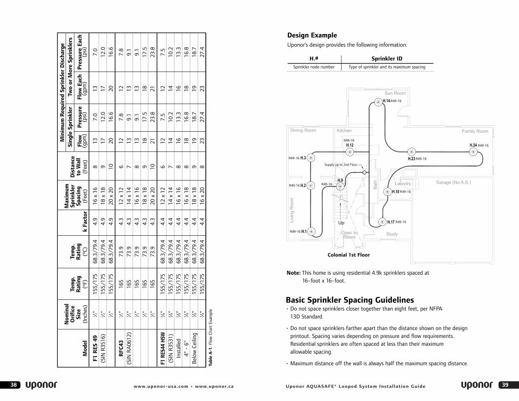
Basic Sprinkler Spacing Guidelines• Do not space sprinklers closer together than eight feet, per NFPA
13D Standard.
• Do not space sprinklers farther apart than the distance shown on the designprintout. Spacing varies depending on pressure and flow requirements.Residential sprinklers are often spaced at less than their maximum allowable spacing.
• Maximum distance off the wall is always half the maximum spacing distance.
Nom
inal
Max
imum
Ori
fice
Tem
p.Te
mp.
Spri
nkle
rD
ista
nce
Size
Rat
ing
Rat
ing
Spac
ing
toW
all
Flow
Pre
ssur
eFl
owEa
chP
ress
ure
Each
Mod
el(I
nche
s)(º
F)(º
C)k
Fact
or(F
eet)
(Fee
t)(g
pm)
(psi
)(g
pm)
(psi
)
F1R
ES49
1 ⁄2"15
5/17
568
.3/7
9.4
4.9
16x
168
137.
013
7.0
(SIN
R35
16)
1 ⁄2"15
5/17
568
.3/7
9.4
4.9
18x
189
1712
.017
12.0
1 ⁄2"15
5/17
568
.3/7
9.4
4.9
20x
2010
2016
.620
16.6
RFC
431 ⁄2"
165
73.9
4.3
12x
126
127.
812
7.8
(SIN
RA
0612
)1 ⁄2"
165
73.9
4.3
14x
147
139.
113
9.1
1 ⁄2"16
573
.94.
316
x16
813
9.1
139.
11 ⁄2"
165
73.9
4.3
18x
189
1817
.518
17.5
1 ⁄2"16
573
.94.
320
x20
1021
23.8
2123
.8
F1RE
S44
HSW
3 ⁄8"15
5/17
568
.3/7
9.4
4.4
12x
126
127.
512
7.5
(SIN
R35
31)
3 ⁄8"15
5/17
568
.3/7
9.4
4.4
14x
147
1410
.214
10.2
Inst
alle
d3 ⁄8"
155/
175
68.3
/79.
44.
416
x16
816
13.3
1613
.34"
-6"
3 ⁄8"15
5/17
568
.3/7
9.4
4.4
16x
188
1816
.818
16.8
Bel
owCe
iling
3 ⁄8"15
5/17
568
.3/7
9.4
4.4
18x
189
1918
.719
18.7
3 ⁄8"15
5/17
568
.3/7
9.4
4.4
16x
208
2327
.423
27.4
Tabl
eA
-1:F
low
Char
tEx
ampl
e
Min
imum
Req
uire
dSp
rink
ler
Dis
char
geSi
ngle
Spri
nkle
rTw
oor
Mor
eSp
rink
lers
Design ExampleUponor’s design provides the following information:
H.# Sprinkler IDSprinkler node number Type of sprinkler and its maximum spacing
R49-16
R49-16 R49-16
Colonial 1st Floor
R49-16
R49-16
R49-16
R49-16
R49-16
R49-16
R49-16
Supply up to 2nd Floor
Note: This home is using residential 4.9k sprinklers spaced at 16-foot x 16-foot.
Uponor AQUASAFE® Looped System Installation Guide40 www.uponor-usa.com • www.uponor.ca 41
Notes
42 www.uponor-usa.com • www.uponor.ca 43Uponor AQUASAFE® Looped System Installation Guide
Notes