Embed Size (px)
Citation preview
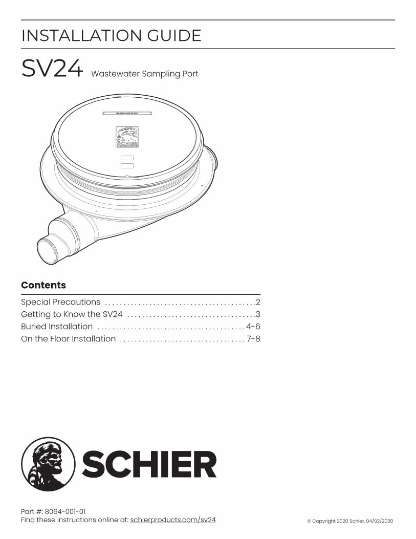
Part #: 8064-001-01Find these instructions online at: schierproducts.com/sv24
Contents
Special Precautions . . . . . . . . . . . . . . . . . . . . . . . . . . . . . . . . . . . . . . . . .2Getting to Know the SV24 . . . . . . . . . . . . . . . . . . . . . . . . . . . . . . . . . . .3Buried Installation . . . . . . . . . . . . . . . . . . . . . . . . . . . . . . . . . . . . . . . . 4-6On the Floor Installation . . . . . . . . . . . . . . . . . . . . . . . . . . . . . . . . . . 7-8
INSTALLATION GUIDE
SV24 Wastewater Sampling Port
© Copyright 2020 Schier, 04/02/2020
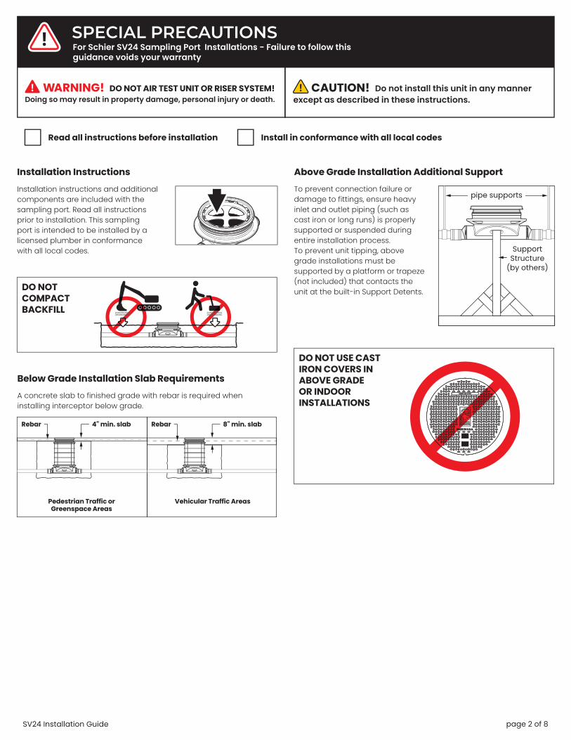
SPECIAL PRECAUTIONS
Installation Instructions
Do not install this unit in any manner
except as described in these instructions.Doing so may result in property damage, personal injury or death.
DO NOT AIR TEST UNIT OR RISER SYSTEM!
For Schier SV24 Sampling Port Installations - Failure to follow this guidance voids your warranty
Installation instructions and additional components are included with the sampling port. Read all instructions prior to installation. This sampling port is intended to be installed by a licensed plumber in conformance with all local codes.
Read all instructions before installation Install in conformance with all local codes
page 2 of 8SV24 Installation Guide
DO NOT COMPACT BACKFILL
To prevent connection failure or damage to fittings, ensure heavy inlet and outlet piping (such as cast iron or long runs) is properly supported or suspended during entire installation process.To prevent unit tipping, above grade installations must be supported by a platform or trapeze (not included) that contacts the unit at the built-in Support Detents.
Above Grade Installation Additional Support
pipe supports
Support Structure
(by others)
A concrete slab to finished grade with rebar is required when installing interceptor below grade.
Below Grade Installation Slab Requirements
Pedestrian Traffic or Greenspace Areas
Vehicular Traffic Areas
Rebar4" min. slab 8" min. slabRebar
DO NOT USE CAST IRON COVERS IN ABOVE GRADE OR INDOOR INSTALLATIONS

GETTING TO KNOW THE SV24
1. Pickable Cast Iron Cover (standard)
2. Cover Gasket
3. Safety Star
4. Safety Star Tether
5. Cover Adapter
6. Cover Adapter Gasket Assembly(x2) with Upper and Lower Stainless Steel Band Clamps
7. Sampling Port Body
8. Above Grade Support Detents (x2)
9. 6" Plain End Connection (achieved by cutting off the 4" connection at the trim line) (x2)
10. 4" Plain End Connection (standard) (x2)
11. Composite Cover Bolts and Washers (x4)
12. Bolted Composite Cover (optional)
13. 7/16" Nut Driver Bit
1
2
3
4
5
6
7
8
9
10
13
11
12
2
page 3 of 8SV24 Installation Guide

Special Precautions
BURIED INSTALLATION
Install sampling port as close as possible to and downstream from interceptor being served
1
Provide at least 16" clearance above unit for
routine maintenance.
2
16" min.
3 Risers (94") Max
4
Max Water LevelRisers are
not designed to retain water
5
3ODOR ALERT!
Interceptor is not a sewer gas trap. All upstream fixtures must
be trapped
page 4 of 8SV24 Installation Guide
Excavate hole at least 12" larger than sampling port on all sides and 6" deeper than port bottom.
Lay a level bed of well-packed, crushed aggregate (approximately 3/4" size rock or sand, with no fines) in the base of hole.
1a 1b
6" or more
12" 12"
6"
1 Excavate Burial Pit
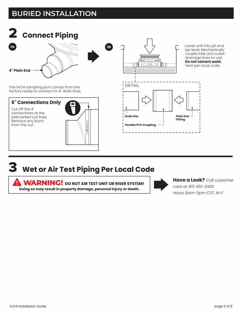
BURIED INSTALLATION
3 Wet or Air Test Piping Per Local Code
Doing so may result in property damage, personal injury or death.DO NOT AIR TEST UNIT OR RISER SYSTEM!
Have a Leak? Call customer
care at 913-951-3300
Hours 8am-5pm CST, M-F
4" Plain End
2b
2 Connect Piping2a Lower unit into pit and
set level. Mechanically couple inlet and outlet drainage lines to unit. Do not solvent weld. Vent per local code.
DETAIL
Flexible PVC Coupling
Plain End Fitting
The SV24 sampling port comes from the factory ready to connect to 4" drain lines.
6" Connections Only
Cut off the 4" connections at the premarked cut lines. Remove any burrs from the cut.
Drain line
page 5 of 8SV24 Installation Guide

BURIED INSTALLATION
4 Bring Cover Flush-to-Grade The SV24 is ready for burial depth of 16" from finished grade to bottom of unit (or 13-1/2" to centerline of inlet). Deeper burials will require extending the Cover Adapter and possibly adding risers.
Measure dimension X to determine riser height needed. 4a
Install riser(s) if required (see instructions included with FCR2).
4b
Riser Height RisersNeeded Required
0" - 4" None (use adapter)
>4" - 34" FCR2 (x1)
>34" - 64" FCR2 (x2)
>64" - 94" FCR2 (x3)
If required, Cover Adapter may now be tilted up to 10º in any direction using gasket flexibility.
4f
Adjust Cover Adapter height as needed. Maintain a minimum 2-1/2" insertion depth.
2-1/2" minimum
4d
Loosen the Cover Adapter Upper Band Clamp using 7/16" Nut Driver Bit.
4c
Tighten Upper Band Clamp to 5 -8 ft. lbs. of torque using 7/16" Nut Driver Bit.
4e
5 Backfill and Finished Grade
TOP VIEW 18"min
45º
18"min
18"min
18"min
Concrete Slab
Rebar
Pour concrete slab to finished grade.
5b
Vehicular Traffic Areas:Minimum 8" thick concrete slab with rebar required. Thickness of concrete around covers to be determined by specifying engineer. If traffic loading is required the concrete slab dimensions shown are for guideline purposes only. Concrete to be 28 day compressive strength to 4,000 PSI. Use No. 4 rebar (ø 1/2") grade 60 steel per ASTM A615: connected with tie wire. Rebar to be 2-1/2" from edge of concrete and spaced in a 12" grid with 4" spacing around access openings.
Pedestrian Traffic or Greenspace Areas:Minimum 4" thick concrete slab with rebar required.
5b1
Rebar
5a
Backfill evenly around tank using crushed aggregate (approximately 3/4" size rock or sand with no fines) or flowable fill. Do not compact backfill around unit.
page 6 of 8SV24 Installation Guide

Special PrecautionsInstall sampling port as close as
possible to and downstream from interceptor being served
1
Use composite cover C24H2 only for above grade installations
2
ON THE FLOOR INSTALLATION
ODOR ALERT!Sampling port is not a sewer gas trap. All
upstream fixtures must be trapped
4
1 Connect Piping1a
4" Plain End
The SV24 sampling port comes from the factory ready to connect to 4" drain lines.
6" Connections Only
Cut off the 4" connections at the premarked cut lines. Remove any burrs from the cut.
FLOOR BELOW INSTALLATION DETAIL
Mechanically couple inlet and outlet drainage lines to unit. Do not solvent weld.Ensure all upstream fixtures are trapped. Vent per local code.
1b
vent per local code
composite cover C24H2
DETAIL
Flexible PVC Coupling
Plain End Fitting
Drain line
ODOR ALERT!Do not install air gap on outlet side of sampling port.
3
Provide at least 16" clearance above unit for
routine maintenance.
16" min.
5
page 7 of 8SV24 Installation Guide

ON THE FLOOR INSTALLATION
2 Install Above Grade Support (by others)
3 Wet or Air Test Piping Per Local Code
Doing so may result in property damage, personal injury or death.DO NOT AIR TEST UNIT OR RISER SYSTEM!
Leak? Call customer care at 913-951-33008a – 5p M – F CST
To prevent tipping and damage to drain line connections, SV24 above grade installations must be supported by a structure (not included) built on-site. The support structure may be a platform or trapeze that contacts the sampling port at the built-in Above Grade Support Detents and is able to hold the weight of the unit.
SIDE VIEW FRONT VIEW
Support Structure (by others - 2x4 wood
framing shown)
Above Grade Support Detents
Composite Cover C24H2
page 8 of 8SV24 Installation Guide