Embed Size (px)
Citation preview
Installation GuideWiser Air™ Thermostat

Wiser Air Installation Guide www.wiserhome.com
English
Safety information
Read these instructions carefully and look at the equipment to become familiar with the device before trying to install, operate, service or maintain it. The following special messages may appear throughout this installation guide or on the equipment to warn of potential hazards or to call attention to information that clarifies or simplifies a procedure.
The addition of either symbol to a “Danger” or “Warning” safety label indicates that an electrical hazard exists which will result in personal injury if the instructions are not followed.
This is the safety alert symbol. It is used to alert you to potential personal injury hazards. Obey all safety messages that follow this symbol to avoid possible injury or death.
DANGER indicates a hazardous situation which, if not avoided, will result in death or serious injury.
WARNING indicates a hazardous situation which, if not avoided, could result in death or serious injury.
NOTICE is used to address practices not related to physical injury.
Please Note
Electrical equipment should be installed, operated, serviced, and maintained only by qualified personnel. No responsibility is assumed by Schneider Electric for anyconsequences arising out of the use of this material.
A qualified person is one who has skills and knowledge related to the construction, installation, and operation of electrical equipment and has received safety training to recognize and avoid the hazards involved.
DANGER
WARNING
NOTICE
1
English
© 2
015
Sch
neid
er E
lect
ric. A
ll rig
hts
rese
rved
.
Wiser Air Installation Guide www.wiserhome.com
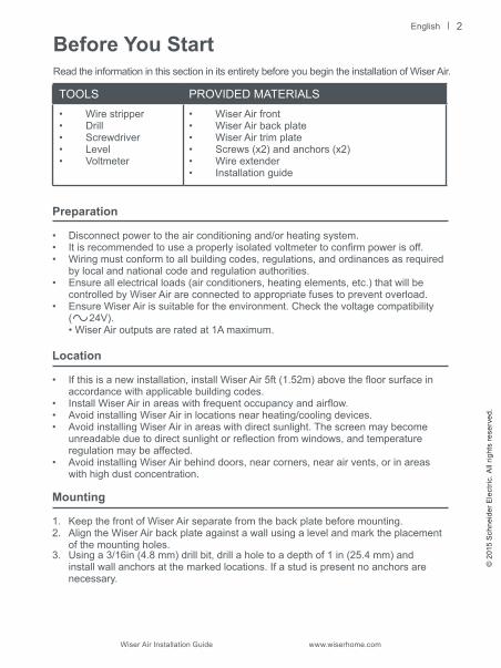
Before You StartRead the information in this section in its entirety before you begin the installation of Wiser Air.
TOOLS PROVIDED MATERIALS• Wire stripper• Drill• Screwdriver• Level• Voltmeter
• Wiser Air front• Wiser Air back plate• Wiser Air trim plate• Screws (x2) and anchors (x2)• Wire extender • Installation guide
2
Preparation
• Disconnect power to the air conditioning and/or heating system.• It is recommended to use a properly isolated voltmeter to confirm power is off. • Wiring must conform to all building codes, regulations, and ordinances as required
by local and national code and regulation authorities.• Ensure all electrical loads (air conditioners, heating elements, etc.) that will be
controlled by Wiser Air are connected to appropriate fuses to prevent overload.• Ensure Wiser Air is suitable for the environment. Check the voltage compatibility
( 24V). • Wiser Air outputs are rated at 1A maximum.
Location
• If this is a new installation, install Wiser Air 5ft (1.52m) above the floor surface in accordance with applicable building codes.
• Install Wiser Air in areas with frequent occupancy and airflow.• Avoid installing Wiser Air in locations near heating/cooling devices.• Avoid installing Wiser Air in areas with direct sunlight. The screen may become
unreadable due to direct sunlight or reflection from windows, and temperature regulation may be affected.
• Avoid installing Wiser Air behind doors, near corners, near air vents, or in areas with high dust concentration.
Mounting
1. Keep the front of Wiser Air separate from the back plate before mounting.2. Align the Wiser Air back plate against a wall using a level and mark the placement
of the mounting holes.3. Using a 3/16in (4.8 mm) drill bit, drill a hole to a depth of 1 in (25.4 mm) and
install wall anchors at the marked locations. If a stud is present no anchors are necessary.
Wiser Air Installation Guide www.wiserhome.com
English
Cleaning and care
• Use a soft, lint-free dry cloth for cleaning.• Avoid getting moisture in openings.• Do not use cleaning products or compressed air.• Never use tools directly on the touchscreen.• Never use paint on Wiser Air.• Do not drop or crush Wiser Air, or allow Wiser Air to come into contact with liquids.• Do not use a damaged device (such as one with a cracked screen).• Functionality guarantees are no longer valid if the glass on the screen is broken.
Wiser Air product supportThe Customer Care Center (CCC) is your single point of contact for information about your Wiser Air. Qualified personnel are available to answer your customer service and technical support questions.PHONE: 1-855-55WISER (1-855-559-4737)E-Mail: [email protected]: www.wiserhome.com/support
Installation Procedure
MERCURY HAZARD
If replacing an existing thermostat that uses a sealed tube of mercury, do not dispose of the tube in the trash. Contact local waste management authorities for information on the safe disposal or recycling of the mercury.
Failure to safely dispose of the mercury can result in exposure leading to serious health damage.
Optional trim plate mounting
If you are replacing an existing thermostat, you have the option of using the provided Wiser Air trim plate. If the hole left by the removal of the existing unit is larger than the back plate of the Wiser Air thermostat, use the optional trim plate. Run the wires and anchor the mounting screws through it while attaching the back plate to the wall (Fig. 2). Make sure to attach the trim plate with the central hole oriented upwards.
WARNING
3
English
© 2
015
Sch
neid
er E
lect
ric. A
ll rig
hts
rese
rved
.
Wiser Air Installation Guide www.wiserhome.com
Installing Wiser Air
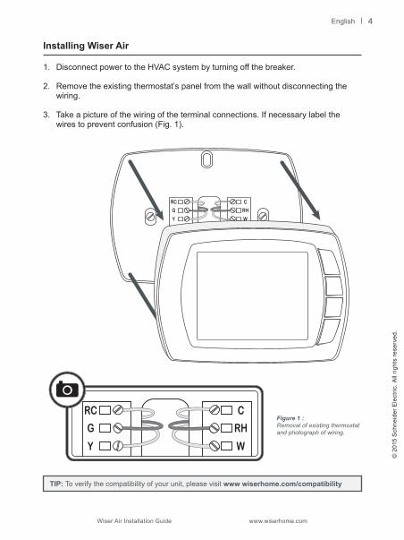
1. Disconnect power to the HVAC system by turning off the breaker.
2. Remove the existing thermostat’s panel from the wall without disconnecting the wiring.
3. Take a picture of the wiring of the terminal connections. If necessary label the wires to prevent confusion (Fig. 1).
Figure 1 : Removal of existing thermostat and photograph of wiring.
TIP: To verify the compatibility of your unit, please visit www wiserhome.com/compatibility
4
Wiser Air Installation Guide www.wiserhome.com
English
TIP: Before proceeding further determine if you require the optional trim plate.
TIP: Before proceeding further check if you require a wire extender (see Appendix).
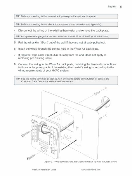
4. Disconnect the wiring of the existing thermostat and remove the back plate.
TIP: Acceptable wire gauge for use with Wiser Air is solid 18 to 22 AWG (0.33 to 0.82mm²). 5. Pull the wires 6in (15cm) out of the wall if they are not already pulled out.
6. Insert the wires through the central hole in the Wiser Air back plate.
7. If required, strip each wire 0.25in (0.6cm) from the end (does not apply to replacing pre-existing units).
8. Connect the wiring to the Wiser Air back plate, matching the terminal connections to those in the photograph of the existing thermostat’s wiring or according to the wiring requirements of your HVAC system.
TIP: See the Wiring terminals section (p.7) in this guide before going further, or contact the Customer Care Center for assistance if necessary.
Figure 2 : Wiring connection and back plate attachment (optional trim plate shown).
5
English
© 2
015
Sch
neid
er E
lect
ric. A
ll rig
hts
rese
rved
.
Wiser Air Installation Guide www.wiserhome.com
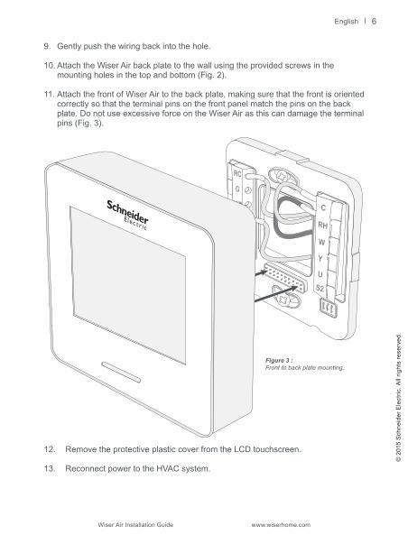
Figure 3 :Front to back plate mounting.
9. Gently push the wiring back into the hole.
10. Attach the Wiser Air back plate to the wall using the provided screws in the mounting holes in the top and bottom (Fig. 2).
11. Attach the front of Wiser Air to the back plate, making sure that the front is oriented correctly so that the terminal pins on the front panel match the pins on the back plate. Do not use excessive force on the Wiser Air as this can damage the terminal pins (Fig. 3).
12. Remove the protective plastic cover from the LCD touchscreen.
13. Reconnect power to the HVAC system.
6
Wiser Air Installation Guide www.wiserhome.com
English
RC
G
W2
Y2
O/B
S1
C
RH
W
Y
U
S2
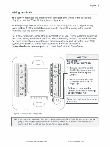
Wiring terminals
This section describes the procedure for connecting the wiring to the back plate.(Fig. 4) shows the Wiser Air backplate configuration.
When replacing an older thermostat, refer to the photograph of the original wiring taken in Step 3 of the installation procedure to connect the wiring to the correct terminals. See the caution below.
For a new installation, consult the documentation for your HVAC system to determine the correct wiring terminal connections. Match the wiring labels to the terminal labels. For more information or assistance in determining the correct wiring for your HVAC system, see the HVAC wiring help sections on the Wiser Air website (www.wiserhome.com/support) or contact the Customer Care Center.
Figure 4 : Wiring terminals and jumper.
7
Failure to remove this jumper can cause damage to your Wiser Air.
EQUIPMENT OPERATION HAZARD
• If a wire is connected to the RH terminal you must remove the backplate jumper.
• Never use any tools on screwless terminals of Wiser Air.
Save the backplate jumper for future use.
NOTICE
TIP: If you are unsure whether your wiring requires the use of the Wiser Air jumper, remove the jumper and test the system to see if the heating comes on. If it does, your installation is complete. If it does not, contact the Customer Care Center.

English
© 2
015
Sch
neid
er E
lect
ric. A
ll rig
hts
rese
rved
.
Wiser Air Installation Guide www.wiserhome.com
Troubleshooting
If you experience difficulties with your Wiser Air thermostat setup, proceed as follows:
• Disconnect power.• Check that the front plate of Wiser Air is properly connected to the back plate.• Check that the wires connected to the terminals on the back plate are properly
attached.
Terminal descriptions
RC Cool 24V power supply Required
G Fan relay
W2 Heating relay (Stage 2)
Y2 Compressor relay (Stage 2)
O/B Cool/Heat active reversing valve
S1 Outside air sensor
C Common Required
RH Heat 24V power supply Only if RC is connected
W Heating relay
Y Compressor relay
U Universal (W3)
S2 Outside air sensor
Connection Description Notes
8
Wiser Air Installation Guide www.wiserhome.com
English
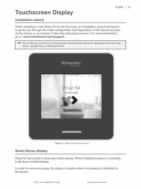
Touchscreen DisplayInstallation wizard
When installing a new Wiser Air for the first time, an installation wizard will launch to guide you through the initial configuration and registration of the device as soonas the device is connected. Follow the instructions shown. For more information,go to: www.wiserhome.com/support.
TIP: For on-the-go control of your thermostat, download the Wiser Air application from the App Store, Google Play or Microsoft Store.
Smart Sense display
Wiser Air has a built-in advanced motion sensor. When it detects a person in proximity,it will show a limited display.
In order to conserve energy, the display is inactive when no presence is detected by the sensor.
Figure 5 : Wiser Air welcome screen.
9
English
© 2
015
Sch
neid
er E
lect
ric. A
ll rig
hts
rese
rved
.
Wiser Air Installation Guide www.wiserhome.com
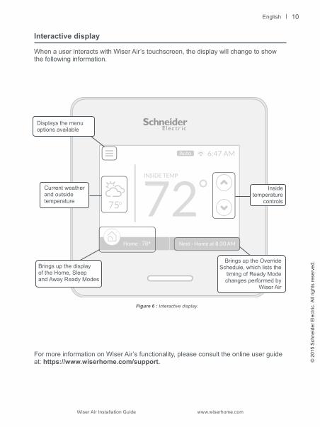
Interactive display
When a user interacts with Wiser Air’s touchscreen, the display will change to show the following information.
72INSIDE TEMP
6:47 AM
Next - Home at 8:30 AMHome - 78
75
Auto
For more information on Wiser Air’s functionality, please consult the online user guide at: https://www.wiserhome.com/support.
Figure 6 : Interactive display.
Brings up the displayof the Home, Sleepand Away Ready Modes
Brings up the Override Schedule, which lists the
timing of Ready Modechanges performed by
Wiser Air
Displays the menu options available
Insidetemperature
controls
Current weather and outside temperature
10

Wiser Air Installation Guide www.wiserhome.com
English
AppendixWiser Wire Extender KitIntroduction
The Wiser Wire Extender Kit is intended for use when a common wire (C) from the HVAC control board is not available. If you are unsure whether you have the HVAC wire present, refer to the picture taken in Step 3 of the Installation procedure for Wiser Air. The picture can also help you determine whether you have a 4 or 5-wire system.
The wire extender kit contains a diode pair and a Printed Circuit Board (PCB) assembly. To open the board, pinch and pull (Fig. 7).
Figure 7 : Wire Extender Kit.
WY
HAZARD OF ELECTRICAL SHOCK
The following installation procedure should be performed by qualified personnel:• Knowledgeable about and licensed in accordance with local electrical installation code requirements.• Able to read, interpret, and follow the instructions and precautions provided.• Trained on the operation and fundamentals of residential HVAC apparatus, and
familiar with the associated hazards.
Failure to follow these instructions can result in personal injury and/or damage to Wiser Air.
WARNING
11
English
© 2
015
Sch
neid
er E
lect
ric. A
ll rig
hts
rese
rved
.
Wiser Air Installation Guide www.wiserhome.com
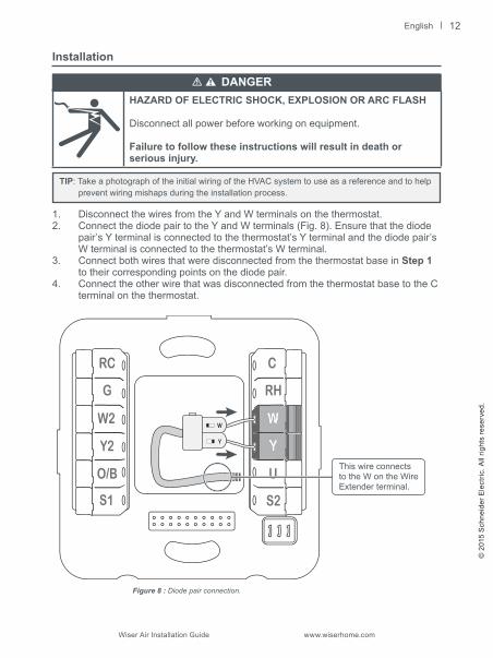
Installation
HAZARD OF ELECTRIC SHOCK, EXPLOSION OR ARC FLASH
Disconnect all power before working on equipment.
Failure to follow these instructions will result in death or serious injury.
TIP: Take a photograph of the initial wiring of the HVAC system to use as a reference and to help prevent wiring mishaps during the installation process.
1. Disconnect the wires from the Y and W terminals on the thermostat.2. Connect the diode pair to the Y and W terminals (Fig. 8). Ensure that the diode
pair’s Y terminal is connected to the thermostat’s Y terminal and the diode pair’s W terminal is connected to the thermostat’s W terminal.
3. Connect both wires that were disconnected from the thermostat base in Step 1 to their corresponding points on the diode pair.
4. Connect the other wire that was disconnected from the thermostat base to the C terminal on the thermostat.
RC
G
W2
Y2
O/B
S1
C
RH
U
S2
W
Y
Figure 8 : Diode pair connection.
This wire connectsto the W on the Wire Extender terminal.
DANGER
12
Wiser Air Installation Guide www.wiserhome.com
English
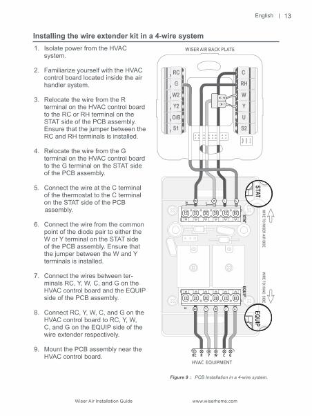
1. Isolate power from the HVAC system.
2. Familiarize yourself with the HVAC control board located inside the air handler system.
3. Relocate the wire from the R terminal on the HVAC control board
to the RC or RH terminal on the STAT side of the PCB assembly. Ensure that the jumper between the RC and RH terminals is installed.
4. Relocate the wire from the G terminal on the HVAC control board to the G terminal on the STAT side of the PCB assembly.
5. Connect the wire at the C terminal of the thermostat to the C terminal on the STAT side of the PCB
assembly.
6. Connect the wire from the common point of the diode pair to either the W or Y terminal on the STAT side of the PCB assembly. Ensure that the jumper between the W and Y terminals is installed.
7. Connect the wires between ter-minals RC, Y, W, C, and G on the HVAC control board and the EQUIP side of the PCB assembly.
8. Connect RC, Y, W, C, and G on the HVAC control board to RC, Y, W, C, and G on the EQUIP side of the wire extender respectively.
9. Mount the PCB assembly near the HVAC control board.
RC
RC R Y W C G
STATEQ
UIP
CRC Y
RH Y W C G
HVAC EQUIPMENT
RC
G
W2
Y2
O/B
S1
C
RH
W
Y
U
S2
WISER AIR BACK PLATEW
IRE TO H
VAC SIDEW
IRE TO W
ISER AIR SIDE
RH W C G
W
Y
Installing the wire extender kit in a 4-wire system
Figure 9 : PCB Installation in a 4-wire system.
13

English
© 2
015
Sch
neid
er E
lect
ric. A
ll rig
hts
rese
rved
.
Wiser Air Installation Guide www.wiserhome.com
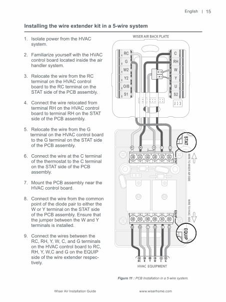
Installing the wire extender kit in a 5-wire system
In order to complete this procedure, ensure that the RC/RH jumper on the STAT side of the PCB is unscrewed and removed.
Figure 10 : Wire extender jumper removal.
14
Wiser Air Installation Guide www.wiserhome.com
English
STATEQ
UIP
GCY
RH Y W C G
RC R Y W C G
RH Y W C G
HVAC EQUIPMENT
RC
WIRE TO
HVAC SIDE
RC
G
W2
Y2
O/B
S1
C
RH
W
Y
U
S2
WISER AIR BACK PLATEW
IRE TO W
ISER AIR SIDE
W
Y
RH W C GRC
Figure 11 : PCB Installation in a 5-wire system.
Installing the wire extender kit in a 5-wire system
1. Isolate power from the HVAC system.
2. Familiarize yourself with the HVAC control board located inside the air handler system.
3. Relocate the wire from the RC terminal on the HVAC control
board to the RC terminal on the STAT side of the PCB assembly.
4. Connect the wire relocated from terminal RH on the HVAC control
board to terminal RH on the STAT side of the PCB assembly.
5. Relocate the wire from the G terminal on the HVAC control board
to the G terminal on the STAT side of the PCB assembly.
6. Connect the wire at the C terminal of the thermostat to the C terminal on the STAT side of the PCB assembly.
7. Mount the PCB assembly near the HVAC control board.
8. Connect the wire from the common point of the diode pair to either the W or Y terminal on the STAT side of the PCB assembly. Ensure that the jumper between the W and Y terminals is installed.
9. Connect the wires between the RC, RH, Y, W, C, and G terminals on the HVAC control board to RC, RH, Y, W,C and G on the EQUIP side of the wire extender respec-tively.
15
English
© 2
015
Sch
neid
er E
lect
ric. A
ll rig
hts
rese
rved
.
Wiser Air Installation Guide www.wiserhome.com
Electrical equipment should be installed, operated, serviced, and maintained only by qualified personnel. No responsibility is assumed by Schneider Electric for any consequences arising out of the use of this material.
© 2015 Schneider Electric. All rights reserved. Schneider Electric and Wiser are trademarks owned by Schneider Electric Industries SAS or its affiliated companies. All other trademarks are the property of their respective owners.
Wiser - IG-US-15.07.2015 V13.4
16
Español
© 2015 S
chneider Electric. Todos los derechos reservados.
Guía de instalación de Wiser Air www.wiserhome.com
Solo el personal calificado puede instalar, operar, reparar y mantener el equipo eléctrico.Schneider Electric no se hace responsable de ninguna consecuencia derivada del uso de este material.
© 2015 Schneider Electric. Todos los derechos reservados.Schneider Electric y Wiser son marcas registradas de Schneider Electric Industries SAS o de susempresas asociadas. Otras marcas registradas son propiedad de sus respectivos dueños.
Wiser - IG-US-15.07.2015 V13.4
16
Guía de instalación de Wiser Air www.wiserhome.com
Español
STAT
EQU
IP
G C Y
RHYWCG
RCRYWCG
RHYWCG
EQUIPO HVAC
RC
DE C
ABLE
A H
VAC
RC
G
W2
Y2
O/B
S1
C
RH
W
Y
U
S2
BASE DE CABLEADODE
CAB
LE A
WIS
ER A
IR
W
Y
RHWCG RC
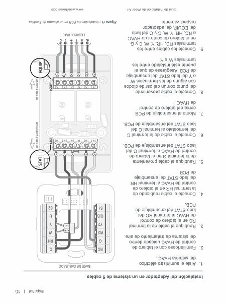
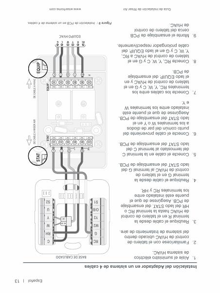
Figura 11 : Instalación del PCB en un sistema de 5 cables.
Instalación del Adaptador en un sistema de 5 cables
1. Aísle el suministro eléctrico del sistema HVAC .
2. Familiarícese con el tablero de control de HVAC ubicado dentro del sistema de tratamiento de aire.
3. Reubique el cable de la terminal RC en el tablero de control de HVAC al terminal RC del lado STAT del ensamblaje de
PCB. 4. Conecte el cable reubicado de la terminal HR en el tablero de control de HVAC al terminal HR del lado STAT del ensamblaje de PCB. 5. Reubique el cable proveniente de la terminal G en el tablero de control de HVAC al terminal G del lado STAT del ensamblaje de PCB.
6. Conecte el cable de la terminal C del termostato al terminal C del lado STAT del ensamblaje de PCB. 7. Monte el ensamblaje de PCB cerca del tablero de control de HVAC.
8. Conecte el cable proveniente del punto común del par de diodos con alguno de los terminales W o Y del lado STAT del ensamblaje de PCB. Asegúrese de que el puente esté instalado entre los terminales W e Y.
9. Conecte los cables entre los terminales RC, HR, Y, W, C y G en el tablero de control de HVAC a RC, HR, Y, W, C y G del lado del EQUIP. del adaptador respectivamente.
15
Español
© 2015 S
chneider Electric. Todos los derechos reservados.
Guía de instalación de Wiser Air www.wiserhome.com
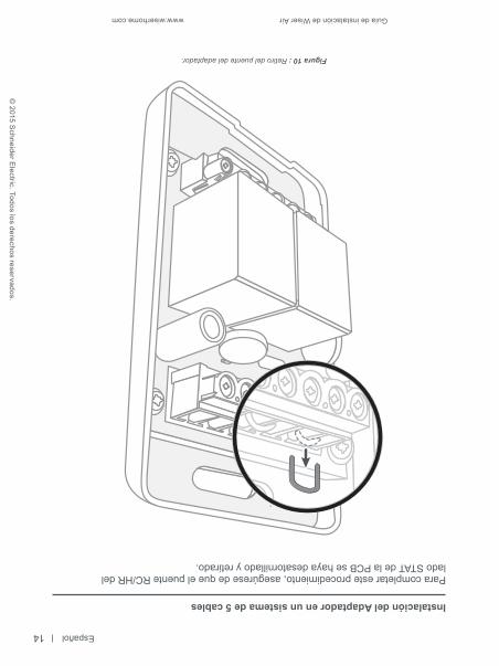
Instalación del Adaptador en un sistema de 5 cables
Para completar este procedimiento, asegúrese de que el puente RC/HR dellado STAT de la PCB se haya desatornillado y retirado.
Figura 10 : Retiro del puente del adaptador.
14
Guía de instalación de Wiser Air www.wiserhome.com
Español
1. Aísle el suministro eléctrico de sistema HVAC.
2. Familiarícese con el tablero de control de HVAC ubicado dentro del sistema de tratamiento de aire.
3. Reubique el cable desde la terminal R en el tablero de control de HVAC hasta la terminal RC o HR del lado STAT. del ensamblaje de PCB. Asegúrese de que el puente esté instalado entre los terminales RC y HR.
4. Reubique el cable desde la terminal G en el tablero de control de HVAC al terminal G del lado STAT del ensamblaje de PCB.
5. Conecte el cable en la terminal C del termostato al terminal C del lado STAT del ensamblaje de PCB.
6. Conecte el cable proveniente del punto común del par de diodos a los terminales W o Y en el lado STAT del ensamblaje de PCB. Asegúrese de que el puente esté instalado entre los terminales W e Y.
7. Conecte los cables entre los terminales RC, Y, W, C y G en el tablero de control de HVAC y en el lado EQUIP. del ensamblaje de PCB.
8. Conecte RC, Y, W, C y G en el tablero de control de HVAC a RC, Y, W, C y G en el lado EQUIP. del cable prolongador respectivamente.
9. Monte el ensamblaje de PCB cerca del tablero de control de HVAC.
RC
RCRYWCG
STAT
EQU
IP
C RCY
RHYWCG
RC
G
W2
Y2
O/B
S1
C
RH
W
Y
U
S2
RHWCG
W
Y
EQUIPO HVAC
DE C
ABLE
A H
VAC
BASE DE CABLEADODE
CAB
LE A
WIS
ER A
IR
Instalación del Adaptador en un sistema de 4 cables
Figura 9 : Instalación de PCB en un sistema de 4 cables.
13

Español
© 2015 S
chneider Electric. Todos los derechos reservados.
Guía de instalación de Wiser Air www.wiserhome.com
Instalación
PELIGRO DE DESCARGA ELÉCTRICA, EXPLOSIÓN OARCO ELÉCTRICODesconecte la alimentación antes de trabajar en el equipo.
El no seguir estas instrucciones, puede ocasionar la muerte o lesiones graves.
CONSEJO : Tome una fotografía del cableado inicial del sistema HVAC para utilizarla como referencia y para prevenir accidentes de cableado durante el proceso de instalación.
1. Desconecte los cables de los terminales Y y W en el termostato.2. Conecte el par de diodos a los terminales (Fig. 8). Asegúrese de que la
terminal Y del par de diodos esté conectada al terminal Y del termostato y que la terminal W del par de diodos esté conectada al terminal W del termostato.
3. Conecte los dos cables que se habían desconectado de la base del termostato en el Paso 1 a sus puntos correspondientes en el par de diodos.
4. Conecte el otro cable que se había desconectado de la base del termostato al terminal C en el termostato.
RC
G
W2
Y2
O/B
S1
C
RH
U
S2
W
Y
Figura 8 : Conexión de par de diodos.
Este cable se conectacon el W en la terminaldel Adaptador.
PELIGRO
12

Guía de instalación de Wiser Air www.wiserhome.com
Español
Apéndice | AdaptadorIntroduction
El Adaptador de Wiser se utiliza cuando no hay cables comunes (C)en el tablero de control de HVAC. Si no está seguro de tener el cable HVAC, consultela fotografía que tomó en el Paso 3 del procedimiento de instalación de Wiser Air.
La fotografía también lo ayudará a determinar si su sistema es de 4 o 5 cables.El Adaptador contiene un par de diodos y una Tarjeta de circuito impreso(PCB por sus siglas en inglés) Para abrir el tablero, tómelo y hale de él (Fig. 7).
Figura 7 : Adaptador Wiser Air.
W Y
PELIGRO DE DESCARGA ELÉCTRICAEl siguiente procedimiento de instalación debe ser realizado por personalcalificado:• Con conocimientos sobre el tema y la habilitación correspondiente a los requerimientos de los códigos locales de instalaciones eléctricas.• Capaz de leer, interpretar y seguir las instrucciones y precauciones provistas.• Capacitado en la operación y en las reglas básicas de aparatos HVAC y familiarizado con los riesgos asociados.Al no seguir estas instrucciones, puede provocar lesiones personalesy/o daños al Wiser Air.
ADVERTENCIA
11

Español
© 2015 S
chneider Electric. Todos los derechos reservados.
Guía de instalación de Wiser Air www.wiserhome.com
Pantalla interactiva
Cuando el usuario interactúa con la pantalla táctil del Wiser Air, se muestraen pantalla la siguiente información.
72INSIDE TEMP
6:47 AM
Next - Home at 8:30 AM Home - 78
75
Auto
Si desea obtener más información sobre las características del Wiser Air, consultela guía del usuario en línea en : https://www.wiserhome.com/support.
Figura 6 : Pantalla interactiva.
Muestra la pantalla de los Modos Hogar (Home), Dormir (Sleep)y Fuera (Away)
Aparece el menúde opcionesdisponible
Controles detemperatura
interior
Clima actualy temperaturaexterior
Muestra la Programaciónde anulación, que enumera
la temporización de loscambios de Modo Listo (Ready) efectuados por
Wiser Air
10
Guía de instalación de Wiser Air www.wiserhome.com
Español
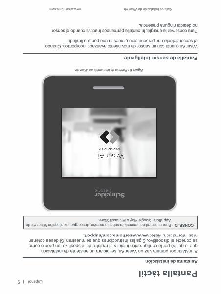
Pantalla táctilAsistente de instalación
Al instalar por primera vez un Wiser Air, se iniciará un asistente de instalaciónque lo guiará por la configuración inicial y el registro del dispositivo tan pronto como se conecte el dispositivo. Siga las instrucciones que se muestran. Si desea obtener más información, visite: www.wiserhome.com/support.
CONSEJO : Para el control del termostato sobre la marcha, descargue la aplicación Wiser Air de App Store, Google Play o Microsoft Store.
Pantalla de sensor inteligente
Wiser Air cuenta con un sensor de movimiento avanzado incorporado. Cuandoel sensor detecta una persona cerca, muestra una pantalla limitada.
Para conservar la energía, la pantalla permanece inactiva cuando el sensorno detecta ninguna presencia.
Figura 5 : Pantalla de bienvenida de Wiser Air.
9

Español
© 2015 S
chneider Electric. Todos los derechos reservados.
Guía de instalación de Wiser Air www.wiserhome.com
Resolución de problemas
Si tiene dificultades para configurar el termostato de su Wiser Air, proceda de lasiguiente manera:
• Desconecte la alimentación eléctrica.• Verifique que la Pantalla del termostato Wiser Air esté correctamente conectada
a la placa posterior.• Verifique que los cables conectados a los terminales de la placa posterior se
hayan fijado correctamente.
Descripciones de la terminal
RCSuministro eléctrico para enfriamiento (24V)Requerido
GRelevador de ventilador
W2Relevador de calefacción (Etapa 2)
Y2Relevador del compresor (Etapa 2)
O/BVálvula de inversión activade enfriamiento / calefacción
S1Sensor de temperatura exterior
CComúnRequerido
RHSuministro eléctrico de calefacción de 24VSolo si RCestá conectado
WRelevador de calefacción
YRelevador del compresor
UUniversal (W3)
S2Sensor de temperatura exterior
Conexión Descripción Notas
8
Guía de instalación de Wiser Air www.wiserhome.com
Español
RC
G
W2
Y2
O/B
S1
C
RH
W
Y
U
S2
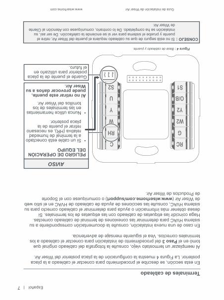
Terminales de cableado
En esta sección, se describe el procedimiento para conectar el cableado a la placaposterior. La Figura 4 muestra la configuración de la placa posterior del Wiser Air.
Al reemplazar un termostato viejo, consulte la fotografía del cableado original quetomó en el Paso 3 del procedimiento de instalación para conectar el cableado a losterminales correctos. Vea el siguiente mensaje de advertencia.
En caso de una nueva instalación, consulte la documentación correspondiente a susistema HVAC para determinar las conexiones de terminal de cableado correctas.Haga coincidir las etiquetas de cableado con las etiquetas de los terminales. Sidesea obtener más información o ayuda para determinar el cableado correcto para susistema HVAC, consulte las secciones de ayuda de cableado de HVAC en el sitio webde Wiser Air (www.wiserhome.com/support) o comuníquese con el Soportede Productos de Wiser Air.
Figura 4 : Base de cableado y puente.
Al no retirar este puente, puede provocar daños a su Wiser Air.
PELIGRO DE OPERACIÓNDEL EQUIPO
• Si un cable está conectado a la terminal de humedad relativa (HR), es necesario retirar el puente de la placa posterior.
• Nunca utilice herramientas en las terminales de los tornillos del Wiser Air.
Guarde el puente de la placa posterior para utilizarlo en el futuro.
AVISO
7
CONSEJO : Si no está seguro de que su cableado requiera el puente del Wiser Air, retire el puente y pruebe el sistema para ver si se enciende la calefacción. De ser así, su instalación se ha completado. De lo contrario, comuníquese con Atención al Cliente de Wiser Air.
Español
© 2015 S
chneider Electric. Todos los derechos reservados.
Guía de instalación de Wiser Air www.wiserhome.com
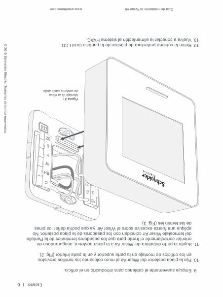
Figura 3 :Montaje de la placade adelante hacia atrás.
9. Empuje suavemente el cableado para introducirlo en el orificio.
10. Fije la placa posterior del Wiser Air al muro colocando los tornillos provistos en los orificios de montaje en la parte superior y en la parte inferior (Fig. 2).
11. Sujete la parte delantera del Wiser Air a la placa posterior, asegurándose de orientar correctamente el frente para que los pasadores terminales de la Pantalla del termostato Wiser Air coincidan con los pasadores de la placa posterior. No aplique una fuerza excesiva sobre el Wiser Air, ya que podría dañar los pines de las termin les (Fig. 3).
12. Retire la cubierta protectora de plástico de la pantalla táctil LCD.13. Vuelva a conectar la alimentación al sistema HVAC.
6

Guía de instalación de Wiser Air www.wiserhome.com
Español
CONSEJO : Antes de continuar, determine si necesitará la placa posterior opcional.
CONSEJO : Antes de continuar, verifique si necesita un Adaptador (ver Apéndice).
4. Desconecte el cableado del termostato existente y retire la placa posterior.
CONSEJO : El calibre de cable aceptable para utilizar con Wiser Air es un AWG sólido de 18 to 22 AWG (0.33 to 0.82mm²).
5. Jale los cables hacia afuera del muro, dejando un largo de 6 pulgadas (15cm).
6. Inserte los cables por el orificio central en la placa posterior del Wiser Air.
7. De ser necesario, pele cada cable de 0,25 pulg (0,6 cm) desde el extremo (esto no se hace cuando se reemplazan unidades existentes).
8. Conecte el cableado a la placa posterior del Wiser Air, haciendo coincidir las conexiones de la terminal con las de la fotografía del cableado del termostato existente o siguiendo los requerimientos de su sistema HVAC.
CONSEJO : Antes de continuar, consulte la sección de terminales de cableado (pág. 7) de esta guía o, de ser necesario, comuníquese con Soporte de Productos de Wiser.
Figura 2 : Conexión de cableado y fijación de la placa posterior (se muestra la placa posterior opcional).
5
Español
© 2015 S
chneider Electric. Todos los derechos reservados.
Guía de instalación de Wiser Air www.wiserhome.com
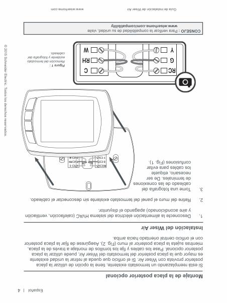
Montaje de la placa posterior opcional
Si está reemplazando un termostato existente, tiene la opción de utilizar la placaposterior provista con Wiser Air. Si el orificio que queda al retirar la unidad existentees mayor que la placa posterior del termostato del Wiser Air, puede utilizar la placaposterior opcional. Pase los cables y fije los tornillos de montaje a través de la placa,mientras sujeta la placa posterior al muro (Fig. 2). Asegúrese de fijar la placa posteriorcon el orificio central orientado hacia arriba.
Instalación del Wiser Air
1. Desconecte la alimentación eléctrica del sistema HVAC (calefacción, ventilación y aire acondicionado) apagando el disyuntor.
2. Retire del muro el panel del termostato existente sin desconectar el cableado.
3. Tome una fotografía del cableado de las conexiones de terminales. De ser necesario, etiquete los cables para evitar confusiones (Fig. 1).
Figura 1 : Remoción del termostato existente y fotografía del cableado.
CONSEJO : Para verificar la compatibilidad de su unidad, visite www.wiserhome.com/compatibility
4
Guía de instalación de Wiser Air www.wiserhome.com
Español
Limpieza y cuidado
• Para la limpieza, utilice un paño suave, seco y sin pelusas.• Evite que se filtre humedad por las aberturas.• No utilice productos de limpieza o aire comprimido.• Nunca utilice herramientas directamente sobre la pantalla táctil.• Nunca utilice pintura sobre el Wiser Air.• No permita que el Wiser Air se caiga o se golpee, ni que entre en contacto
con líquidos.• No utilice un dispositivo dañado (por ejemplo, con la pantalla quebrada), ya que
podría provocar lesiones.• Las garantías de funcionamiento pierden validez cuando se rompe el cristal de
la pantalla.
Soporte de producto de Wiser AirEl Centro de Atención al Cliente (CAC) es su único punto de contacto para obtenerinformación acerca de su Wiser Air. Contamos con personal calificado disponiblepara responder sus preguntas técnicas y del servicio al cliente.TELÉFONO: 1-855-55WISER (1-855-559-4737)Correo electrónico: [email protected]ágina Web: www.wiserhome.com/support
Procedimiento de instalación
SOBRE EL PELIGRO DE MERCURIOSi está reemplazando un termostato existente que utiliza un tubo sellado demercurio, no deseche el tubo en la basura. Comuníquese con las autoridadeslocales de gestión de residuos para obtener información acerca de la eliminaciónsegura o del reciclado del mercurio.Si no desecha el mercurio de forma segura, puede provocar una exposiciónque conlleva daños graves para la salud.
Montaje
1. Mantenga la Pantalla del termostato Wiser Air separada de la placa posterior antes de proceder al montaje.
2. Alinee la placa posterior del Wiser Air contra un muro, con ayuda de un nivel, y marque la ubicación de los orificios de montaje.
3. Usando broca de 3/16” (4.8 mm), taladre un agujero a una profundidad de 1” (25.4 mm) e instale taquetes en las ubicaciones marcadas. Si hay una viga presente no es necesario el uso de taquetes.
3
ADVERTENCIA
Español
© 2015 S
chneider Electric. Todos los derechos reservados.
Guía de instalación de Wiser Air www.wiserhome.com
Antes de comenzarLea toda la información incluida en esta sección antes de comenzar con la instalacióndel Wiser Air.
HERRAMIENTASMATERIALES PROVISTOS• Pelacables• Taladro• Destornillador• Nivel• Voltímetro
• Pantalla del termostato Wiser Air• Base de cableado del termostato Wiser Air• Placa posterior del termostato Wiser Air• Tornillos (x2) y anclajes (x2)• Adaptador• Guía de instalación
Preparación
• Desconecte la alimentación eléctrica del aire acondicionado y/o del sistema de calefacción.
• Se recomienda utilizar un voltímetro aislado adecuadamente para confirmar que la electricidad esté desconectada.
• El cableado debe respetar todos los códigos, regulaciones y ordenanzas de edificación, tal como lo requieren las autoridades regulatorias y los códigos locales y nacionales.
• Asegúrese de que todas las cargas eléctricas (aparatos de aire acondicionado, elementos de calefacción, etc.) que estarán bajo el control de Wiser Air esténconectadas a los fusibles adecuados para evitar sobrecargas.
• Asegúrese de que Wiser Air sea adecuado para el entorno. Verifique la compatibilidad de voltaje ( 24V).
• Las terminales de cableado de salida soportan máximo 1A cada una.
Ubicación
• Si se trata de una nueva instalación, instale Wiser Air a 5 pies (1,5 m) de la superficie del piso, de conformidad con los códigos de edificación aplicables.
• Instale Wiser Air en zonas con ocupación frecuente y con corriente de aire.• Evite instalar Wiser Air cerca de dispositivos de calefacción/refrigeración.• Evite instalar Wiser Air en zonas que reciben luz solar directa. La pantalla puede
volverse ilegible por el efecto de la luz solar directa o por el reflejo de las venta-nas,lo que podría afectar la regulación de la temperatura.
• Evite instalar Wiser Air detrás de las puertas, cerca de las esquinas, cerca de las salidas de aire o en zonas con alta concentración de polvo.
2
Guía de instalación de Wiser Air www.wiserhome.com
Español
Información de seguridad
Lea cuidadosamente estas instrucciones y observe el equipo para familiarizarsecon el dispositivo antes de realizar su instalación, operación, reparación omantenimiento. Es posible que en esta guía de instalación o en el equipoaparezcan los siguientes mensajes advirtiendo acerca de peligros potenciales orecordándole al usuario información para aclarar o simplificar unprocedimiento.
La presencia de símbolos de “Peligro” o “Advertencia” en la etiquetade seguridad indican que existe un riesgo eléctrico que puede provocarlesiones personales si no se respetan las instrucciones.
Este es el símbolo de alerta de peligro. Se utiliza para alertar sobreposibles riesgos de lesiones personales. Es necesario respetar losmensajes de seguridad que acompañan a este símbolo para evitarposibles lesiones o incluso la muerte.
PELIGRO indica una situación peligrosa que, de no evitarse, ocasionará la muerteo lesiones graves.
ADVERTENCIA indica una situación peligrosa que, de no evitarse, podríaocasionar la muerte o lesiones graves.
AVISO se utiliza para abordar prácticas no relacionadas con lesiones físicas.
Información para tener en cuenta
Solo el personal calificado puede instalar, operar, reparar y mantener el equipoeléctrico. Schneider Electric no se hace responsable de ninguna consecuenciaderivada del uso de este material.
Se considera persona calificada a aquella que cuenta con habilidades yconocimientos relacionados con la construcción, la instalación y la operación deequipos eléctricos y que ha recibido capacitación sobre seguridad para reconocer y evitar los peligros asociados con los equipos en cuestión.
PELIGRO
ADVERTENCIA
AVISO
1

Español
© 2015 S
chneider Electric. Todos los derechos reservados.
Guía de instalación de Wiser Air www.wiserhome.com

Guía de instalaciónTermostato Wiser Air
™