Embed Size (px)
Citation preview
DUO® Exposed Grid Ceiling System
duo
® in
stall
atio
n gu
ide
FEATURES & BENEFITS
FEATURE BENEFIT
Engineer-designed locking tabs on each cross tee
Cross tees can be easily removed from an installed ceiling without damage and then reinstalled at another location. This is convenient when relocating light or air conditioning features. Locking tabs on each cross tee are manufactured from a high tensile steel to provide a strong and positive connection. The cross tee locking tab has been engineered to ensure that it will stay in place in the main tee whilst the opposite cross tee is being installed.
Strong and exclusively designed “zipper” packaging for all standard main and cross tees
Enables ease of opening and reduces the potential for damage. Packaging has also been designed to ensure that it will not break open while it is being transported and allows the carton to maintain it’s integrity for carrying once opened.
Range of snap-on and hooked suspension clips as well as 50mm spaced holes for the tie wire on the main tee
The Rondo DUO® main tee can be suspended anywhere along its length with a choice of suspension clips or tie wire.
All components are produced with protective coatings
Rondo is able to offer a performance guarantee for a minimum of 15 years for most environments.
Code Compliance All components of the Rondo DUO® Exposed Grid Ceiling System have been designed and tested by Rondo engineers to meet the requirements of suspended ceiling and seismic design codes in both Australia and New Zealand.
Technical Expertise For detailed technical information, visit www.rondo.com.au to view the Rondo Professional Design Manual, or download the Rondo App. For all other advice, contact your local Rondo Technical Sales Representative.
GENERAL INFORMATION
This brochure provides details of the Rondo DUO® Exposed Grid Ceiling System, which allows for integration with other Rondo suspended ceiling systems in the same plane. Below are just some of the features and benefits of choosing to use the Rondo DUO® grid system, and some of the products available to help meet your construction needs.Note that this brochure is intended to be used as a guide only; full details should be obtained via the Rondo website. Rondo recommends installation by a qualified tradesperson and that you ensure you are referring to the latest version of this guide by comparing it to the one on our website.
rondo duo® EXPOSED GRID CEILING SYSTEM
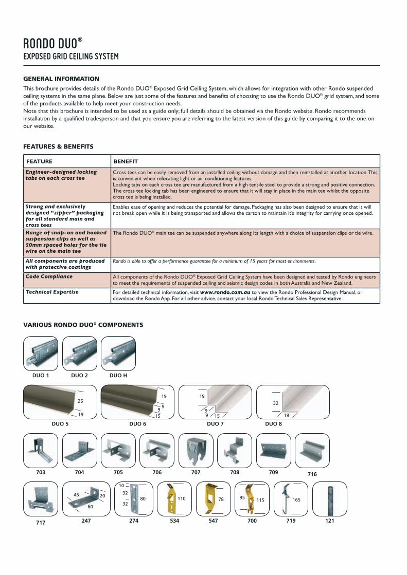
VARIOUS RONDO DUO® COMPONENTS
DUO 1 DUO 2 DUO H
DUO 5 DUO 6 DUO 7 DUO 8
19
3225
19 15
19
99
703 704 705 706 707 708 709 716
717 547247 274 534
45 20
60
8032
10
32110 78
700 719
11595 165
121
15
19
99

1. Select your preferred grid layout to suit either 1200 x 600 or 600 x 600 ceiling panels as shown in Table 1, selecting the relevant cross tee based on the weight of the ceiling tile.
2. Set the grid out from the middle of the room to maintain equal cut panels to opposite walls.
3. Mark the ceiling height on the walls and fix the perimeter trim with suitable fasteners at max. 600mm centres, ensuring the fixing is made into the studs. Mitre the corner intersections and use joiners to connect angles as per Figure 1.
4. Fix the Main Tee suspension brackets as per Figures 2 & 6. Ensure the suspension brackets are installed at no more than 1200mm centres and spaced 1200mm on either side. Ensure the hanger points are set out so that hangers adjacent to the perimeter walls are no more than 300mm from the wall unless otherwise specified.
5. Assemble the Main Tee suspension clip to the suspension rods that have been pre-cut to length to suit your suspension drop. Ensure the suspension is vertical.
6. Ensure the pre-punched slots on the Main Tee line up, and fit the Main Tee to the clips, as per Figure 4. The Main Tees should now be spaced 1200mm apart and suspended 1200mm between hangers. Stagger joints between adjacent Main Tees.
7. Ensure the integrated self locking joiners on Main Tees are properly locked together. Where Main Tees abut the wall trim, secure with the relevant stabiliser clip as per Figure 3.
8. Fix Cross Tees into position through the slots in the Main Tee with a gentle push. The opposing cross tees positively lock together as per Figure 5. The slots in the Main Tee are spaced 100mm apart to ensure the correct space is maintained between the Cross Tees (600mm apart for a 1200 x 600 panel). Cross Tees abutting the wall trim should be secured with the relevant clip, as per Figure 3, at not more than 1800mm centres unless otherwise specified.
9. Finally, align and level the grid by adjusting the suspension clips up or down using a string line or laser as a guide.
600 600
1200
1
1
2 5 2 5 2 5
A
600
600
1
1
5
5 5
1200
C
600
600
1
33
1
600 600
2 5 2 52 5
B
MAIN TEE REF PART NO LENGTH
24
38 1 DUO 1 3600
CROSS TEE REF PART NO LENGTH
24
34
2 DUO 2 1200
3 DUO 2 600
4 DUO H 1200
TABLE 1: TEE SPACING/MAX. ALLOWABLE LOADS
SYSTEM FACE SIZE mm
SPACING OF M/TS
mm
SPACING OF X/TS
mm
ALLOWABLE LOAD
kg/m2kg
MAX. WEIGHT OF LIGHT FITTINGS
kg
ADUO 1–H 24 1200 600 14.2 10
DUO 1–2 24 1200 600 12.4 10
BDUO 1–H 24 1200 600 14.2 10
DUO 1–2 24 1200 600 12.4 10
C DUO 1–H 24 1200 600 8.4 6
709 Joiner
716 Joiner
FIGURE 1: WALL ANGLE JOINERS
rondo duo® TYPICAL APPLICATION DETAILS

FIGURE 2: TWO-WAY EXPOSED CEILING SYSTEM DETAIL
1200 x 600ceiling panels
300mm300mm
One piece suspension clipRondo 700
Tile hold-down clip(optional)
Rondo DUO 1 Main Tee
Rondo 121 5mm suspension rod
Span of main tee1200mm between hangers
Spacing of main tee 1200mm
Rondo 274 suspension rod bracket
Rondo DUO 2 orDUO H Cross Tee
706 Stabiliser Clip
705 Stabiliser Clip
FIGURE 3: STABILISER CLIPS
SQUEEZE
FIGURE 4: INSTALLING THE RONDO 700 SUSPENSION CLIP
FIGURE 5: MAIN AND CROSS TEE JOINTING CROSS
Suspension rodbracket Part No 534
Suspension rod bracket Part No 547
FIGURE 6: ALTERNATIVE SUSPENSION BRACKETS
CrossTee
Main Tee
Self-lockingbutt joint

The installation of troffer type light fittings can be accommodated by installing additional cross tees, but ensuring the weight of the light fitting is borne by the main tees only as Figure 7.
NOTE: For all further information, speak to a Rondo Technical Sales Representative or for full installation details and warranty conditions, please visit our website at www.rondo.com.au, download the Rondo App or speak to your local Authorised Rondo Distributor.
FIGURE 7: LIGHT FITTING DETAIL
NOTE: To ensure the weight of the fitting does not compromise the integrity of the grid additional hangers should be installed adjacent to the fitting if none already exist. See Table 1 for maximum weight of light fittings.
BULKHEADSChanges in ceiling levels can be accommodated by the introduction of vertical bulkheads which can be constructed using plasterboard or ceiling panels as shown in Figures 8 & 9. More detailed information on bulkhead construction, or other DUO® applications such as One Way Exposed ceilings, sloping DUO® ceilings, linear diffusers, and securing partition head tracks to grid, is available in the Rondo Professional Design Manual on the Rondo website, www.rondo.com.au.
FIGURE 8: SQUARELINE BULKHEAD DETAIL (VERTICAL EXPOSED GRID)
FIGURE 9: SQUARELINE BULKHEAD DETAIL (VERTICAL KEY-LOCK®/STEEL STUD SYSTEM)
247 DirectFixing Clip
700 Suspension Clip
700 Suspension Clip
121Suspension Rod
708BulkheadClip
DUO 1 Main Tee
DUO 1 Main Tee
DUO 1 Main Tee
DUO 5 Wall Angle
545 Angle Bracket
DUO 5 Wall Angle
Ceiling Tile
300mm max
Ceiling Tile
300mmmax
220mm min
127 Top Cross Rail
139 Locking Key
247 Direct Fixing Clip
2534Suspension Clip
700 Suspension Clip
121 Suspension Rod
Rondo Steel Stud and Track framing as nominated, braced to structure
717BulkheadClip
DUO 1 Main Tee
DUO 5 Wall Angle
Building Board
Ceiling Tile
300mm max
300mmmax
129Furring Channel

rondo offices
AUSTRALIARONDO BUILDING SERVICES PTY LTDCUSTOMER SERVICE HOTLINE: 1300–36–RONDO (1300–36–7663)
NEW SOUTH WALES57–87 Lockwood Road Erskine Park NSW 2759 (PO Box 324 St Marys NSW 1790)phone: 61–2–9912 7300 fax: 61–2–9912 7310 email: [email protected]
VICTORIA12–14 Dunlop Road Mulgrave VIC 3170(Private Bag 23 Mulgrave VIC 3170)phone: 61–3–8561 2222 fax: 61–3–8561 2266 email: [email protected]
QUEENSLAND13 Binary Street Yatala QLD 4207(PO Box 6006 Yatala QLD 4207)phone: 61–7–3442 6400 fax: 61–7–3442 6427 email: [email protected]
SOUTH AUSTRALIA39 George Street Green Fields SA 5107phone: 61–8–8256 5900 fax: 61–8–8256 5922 email: [email protected]
WESTERN AUSTRALIA5 Hazelhurst Street Kewdale WA 6105(PO Box 168 Cloverdale WA 6985)phone: 61–8–9251 9400 fax: 61–8–9251 9414 email: [email protected]
HEAD OFFICE 57–87 Lockwood Road Erskine Park NSW 2759 (PO Box 324 St Marys NSW 1790) email: [email protected]: 61–2–9912 7303 fax: 61–2–9912 7313
EXPORT phone: 61–438–427–479 fax: 61–7–3287–1881 email: [email protected]
NEW ZEALANDRONDO BUILDING SERVICES PTY LTD117A Captain Springs Road Onehunga Auckland 1061 New Zealand(PO Box 12464 Penrose Auckland 1642 New Zealand)phone: 64–9–636 5110 fax: 64–9–636 5111 email: [email protected] CALL: 0800–0800–RONDO (0800–0800–76)
MALAYSIARONDO METAL PRODUCTS SDN BHDLot 606, Off Jalan SS13/1K47500 Subang Jaya Selangor phone: 60–3–5636 0710 fax: 60–3–5636 0711
INDIARONDO METAL SYSTEMS PVT LTDPlot No. J-21, MIDC Taloja, Tal. PanvelDist. Raigad - 410-208 Mumbai Indiaphone: 91-22-2740 2831
www.rondo.com.au
This brochure is printed on 55% recycled paper and 45% pulp from responsible forestry, FSC® Certified.RONDO® and DUO® are registered trademarks of Rondo Building Services Pty Ltd. ABN 69 000 289 207.
First Printed MAY 2009. Revised OCT 2013.


![Digital holography and its application [5636-31]](https://img.dokumen.tips/doc/110x75/62a4cfb3ebfdd4158c0790aa/digital-holography-and-its-application-5636-31.jpg)


