Embed Size (px)
Citation preview
Installation Guide for TerminEdge Fascia & TerminEdge AR Fascia
4 COMMERCE WAY, ARDEN, NC 28704 USA800.892.9173 828.676.1700
OMGEDGESYSTEMS.COM
Formed Galvanized Steel Retainer for Single-Ply
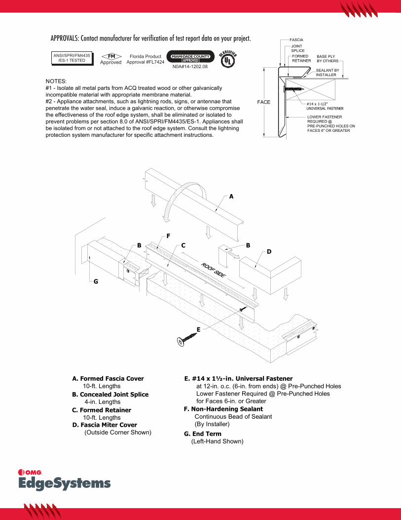
NOTES:#1 - Isolate all metal parts from ACQ treated wood or other galvanically incompatible material with appropriate membrane material. #2 - Appliance attachments, such as lightning rods, signs, or antennae that penetrate the water seal, induce a galvanic reaction, or otherwise compromise the effectiveness of the roof edge system, shall be eliminated or isolated to prevent problems per section 8.0 of ANSI/SPRI/FM4435/ES-1. Appliances shall be isolated from or not attached to the roof edge system. Consult the lightning protection system manufacturer for specific attachment instructions.
BASE PLYBY OTHERS
FORMEDRETAINER
FASCIA
JOINTSPLICE
FACE
LOWER FASTENERREQUIRED @PRE-PUNCHED HOLES ONFACES 6" OR GREATER
#14 x 1-1/2"UNIVERSAL FASTENER
SEALANT BYINSTALLER
FC B
D
A
E
B
F. Non-Hardening Sealant Continuous Bead of Sealant (By Installer)
C. Formed Retainer 10-ft. Lengths
B. Concealed Joint Splice 4-in. Lengths
D. Fascia Miter Cover (Outside Corner Shown)
A. Formed Fascia Cover 10-ft. Lengths
E. #14 x 1½-in. Universal Fastener at 12-in. o.c. (6-in. from ends) @ Pre-Punched Holes Lower Fastener Required @ Pre-Punched Holes for Faces 6-in. or Greater
G
G. End Term (Left-Hand Shown)
APPROVALS: Contact manufacturer for verification of test report data on your project.
ANSI/SPRI/FM4435/ES-1 TESTED
N0A#14-1202.08
Florida ProductApproval #FL7424
FMApproved
S
UL®

STEP 4: Installing Fascia End Caps and End TermsInstall end caps and end terms by hooking top and pressing top facedownward to snap fascia into place (refer to STEP 4).
STEP 1: Consider Sump Core & Spillout LocationsLocate sump cores where downspouts will be located. Sumps areinstalled prior to the retainer. The retainer butts up to side(s) ofsump core. Spillouts are installed along with the fascia lengths asrequired. Refer to "Sump Core & Spillout Install Guide" for more infoon installation if necessary.
JOINTSPLICE
OUTSIDEMITER
BASEPLY
SEALANT
WALLEND
ENDCAP END TERM
JOINTSPLICE
FASCIAMITER
JOINTSPLICE
FASCIASTRAIGHTLENGTH
ATTACH MEMBRANE TO METAL INACCORDANCE WITH THE MEMBRANEMANUFACTURER'S SPECIFICATIONS
SUMPCORE
SPILLOUT
ROOFSIDE
STEP 2: Installing RetainerApply a continuous bead of the roofing manufacturer's sealant to thebottom side of the retainer. Set the retainer onto the roof edge overmembrane placing as close to corner as possible being sure toallow for adjacent retainer. Finally using the mechanical fastenersprovided secure the assembly to the substrate. Butt adjacentretainer to initial and repeat.Note: Pre-drilling for Masonry requires a 3/16-in. Pilot Hole.
HOOK TOPONTO RETAINER
THEN PRESSDOWNWARD
ON TOP FACE TOSNAP INTO POSITION
HOOK TOPONTO RETAINER
THEN PRESSDOWNWARD
ON TOP FACE TOSNAP INTO POSITION
(AS IN STEP 4)
STEP 3: Installing Fascia MitersLocate the miter and concealed joint splice for the appropriate corner. Placea splice in each side of the miter, hook the top flange of the miter onto thetop flange of the retainer rotate the fascia outward towards the outside of thebuilding. Lastly press down on the top flange of the fascia to snap the bottomhook onto the bottom of the retainer. Make sure that the hook of the fasciahas fully engaged onto the retainer.
(DO NOT HOOK THE BOTTOM OF THE SPLICE ONTO THE RETAINER)
STEP 5: Installing Fascia Straight LengthsPlace a concealed joint splice in the opposite end of the installedmiter. Install the fascia by hooking top and pressing top facedownward to snap fascia into place. Allow a 1/4-in. gap betweenfascia sections for thermal expansion. Review lengths of allstraight pieces prior to cutting to avoid creating relatively shortsections of fascia adjacent to full length sections.Note: There must be a splice at every joint.
FORMEDRETAINER
SEALANT(APPLY
CONTINUOUSLYAS SHOWN)
ROOF SIDE
BUTT ADJACENT RETAINERS ASCLOSE TO EDGE AS POSSIBLE
RETAINER
ROOFSIDE

4 COMMERCE WAY, ARDEN, NC 28704 USA800.892.9173 828.676.1700 OMGEDGESYSTEMS.COMCopyright © 2017 OMG, Inc. All rights reserved. EM
1047
Re
v. 0
3242
017
Superior productivity. Superior performance.
Installation Guide for TerminEdge - Sump Cores & Spillouts
SUMP CORES
BASE PLY
STEP 1: Installing Sump CoreLocate sump cores where downspouts will be located. Sumpsare installed prior to the retainer. Fasten sump core to the woodnailer with a min. of (3) 1½-in. ss ring shank nails.
SUMPCORE
STEP 2: Installing Retainer at Sump CoreButt retainer to the sump core. Apply membrane flashing stripinto the sump core as required by membrane manufacturer'sspecifications. Splice and seal the membrane in and around thesump core in accordance with membrane manufacturer'sspecifications.
MEMBRANEFLASHING STRIP
STEP 3: Installing Sump FacePlace a concealed joint splice in each end of sump face. Installsump face by hooking top and pressing top face downward tosnap fascia into place.
RETAINER
SUMPFACE
RETAINER
JOINTSPLICE
SPILLOUTS
BASE PLY
STEP 1: Installing SpilloutSpillouts are installed along with the fascia lengths as required.Spillouts are installed prior to the spring clip. Fasten spillout tothe wood nailer with a min. of (2) 1½-in. ss ring shank nails.
SPILLOUT
STEP 2: Installing retainer at SpilloutButt retainer to the spillout. Apply membrane flashing strip intothe spillout as required by membrane manufacturer'sspecifications. Splice and seal the membrane in and around thespillout in accordance with membrane manufacturer'sspecifications. (DO NOT LEAVE ANY SHARP EDGESAGAINST THE MEMBRANE.)
MEMBRANEFLASHINGSTRIP
STEP 3: Installing Spillout FacePlace a concealed joint splice in end of fascia. Position spilloutfascia in a manner to engage the top of the retainer. Press topface downward to snap fascia into place.
RETAINER
SPILLOUTFACE RETAINER
JOINTSPLICE
JOINTSPLICE
FACTORYNOTCH
WOODNAILER
WOODNAILER
(3) 1½" SS RINGSHANK NAILS
(2) 1½" SS RINGSHANK NAILS
FASCIA