Embed Size (px)
Citation preview
MA3
INSTALLATION GUIDE
This product is intended for installation by a professional installer only! Attempts to install this product by a person other than a trained professional may result in severe damage to a vehicle’s electrical system and components.
2018-02-27
© 2018 Directed, Vista CA
Directed Digital Solutions
Designed by Installers for Installers

ContentsWarning! Safety first ....................................................................................................................... 3Introduction .................................................................................................................................... 4
Pre-installation and application warnings ..................................................................................... 4Vehicle application guide ........................................................................................................... 5
Wiring connections ......................................................................................................................... 6Main power harness (H1), 12-pin thick gauge connector ............................................................... 6Auxiliary output harness (H2), 16-pin black connector ................................................................... 6Analog harness (H3), 18-pin white connector ............................................................................... 7MC501 harness (H4), 8 thick-gauge wires (optional) ..................................................................... 7
Installation (wiring diagrams & vehicle wiring reference charts) ............................................................ 8Type 1 with T-Harness (THMAC1) (Rev-1) ..................................................................................... 8Type 1 ..................................................................................................................................... 9Type 2 with T-Harness (THMAC1) (Rev-1) ................................................................................... 11Type 2 .................................................................................................................................. 12Type 3 with T-Harness (THMAC1) (Rev-1) ................................................................................... 14Type 3 ................................................................................................................................... 15Type 4 with T-Harness (THMAC1) (Rev-1) ................................................................................... 17Type 4 ................................................................................................................................... 18Type 5 ................................................................................................................................... 20Accessing the parking light circuit ............................................................................................ 22Immobilizer interface .............................................................................................................. 22
Connecting the module .................................................................................................................. 23Important! .............................................................................................................................. 23Manual or automatic transmission selection ................................................................................ 23Optional sensors ..................................................................................................................... 23RF Systems ............................................................................................................................. 24When used in conjunction with SmartStart .................................................................................. 24Module programming .............................................................................................................. 25LED diagnostics and troubleshooting .......................................................................................... 27Soft reset ................................................................................................................................ 29Hard reset .............................................................................................................................. 29
Learning the Tach (not needed with Virtual Tach) ............................................................................... 30Initializing Virtual Tach (not needed with hardwired or data tach applications) ..................................... 30Limited lifetime consumer warranty .................................................................................................. 31Quick Reference Guide .................................................................................................................. 32
Warning! Safety firstThe following safety warnings must be observed at all times:
• Due to the complexity of this system, installation of this product must only be performed by an authorized Directed dealer.• When properly installed, this system can start the vehicle via a command signal from the remote control. Therefore, never
operate the system in an area that does not have adequate ventilation.
The following precautions are the sole responsibility of the user; however, authorized Directed dealers should:• Never use a test light or logic probe when installing this unit. Always use a multimeter. • Never operate the system in an enclosed or partially enclosed area without ventilation (such as a garage). • When parking in an enclosed or partially enclosed area or when having the vehicle serviced, the remote start system must
be disabled using the installed toggle switch. It is the user’s sole responsibility to properly handle and keep out of reach from children all remote controls to assure that the system does not unintentionally remote start the vehicle.
• USER MUST INSTALL A CARBON MONOXIDE DETECTOR IN OR ABOUT THE LIVING AREA ADJACENT TO THE VEHICLE. ALL DOORS LEADING FROM ADJACENT LIVING AREAS TO THE ENCLOSED OR PARTIALLY ENCLOSED VEHICLE STORAGE AREA MUST REMAIN CLOSED AT ALL TIMES.
Use of this product in a manner contrary to its intended mode of operation may result in property damage, personal injury, or death. Except when performing the Safety Check outlined in this installation guide, (1) Never remotely start the vehicle with the vehicle in gear, and (2) Never remotely start the vehicle with the keys in the ignition. The user is responsible for having the neutral safety feature of the vehicle periodically checked, wherein the vehicle must not remotely start while the car is in gear. This testing should be performed by an authorized Directed dealer in accordance with the Safety Check outlined in this product installation guide. If the vehicle starts in gear, cease remote start operation immediately and consult with the user to fix the problem immediately.
OPERATION OF THE REMOTE START MODULE IF THE VEHICLE STARTS IN GEAR IS CONTRARY TO ITS INTENDED MODE OF OPERATION. OPERATING THE REMOTE START SYSTEM UNDER THESE CONDITIONS MAY RESULT IN PROPERTY DAMAGE OR PERSONAL INJURY. IMMEDIATELY CEASE THE USE OF THE UNIT AND REPAIR OR DISCONNECT THE INSTALLED REMOTE START MODULE. DIRECTED WILL NOT BE HELD RESPONSIBLE OR PAY FOR INSTALLATION OR REINSTALLATION COSTS.
Remote starters for manual transmission pose significant risks if not properly installed and operated. When testing to ensure the installation is working properly, only remote start the vehicle in neutral gear, on a flat surface and with a functional, fully engaged parking brake. Do not allow anyone to stand in front of or behind the vehicle.
This product should not be installed in any convertible vehicles, soft or hard top with a manual transmission. Installation in such vehicles may pose certain risk.
3 Directed Digital Solutions MA3© 2018-02-27 Directed. All rights reserved.

IntroductionThe MA3 firmware for Directed Digital Solutions is compatible with specific Mazda, Scion and Toyota vehicles. It is a complete solution for remote start, security (if applicable), bypass interface, and convenience. This guide provides information on the installation of the module using MA3. If you would prefer using this system as a digital solution, go to www.directechs.com and search for the make, model and year of the vehicle. This will allow you to find the proper firmware and corresponding installation guide.
Warning! This module can only be programmed via the web tool, which can be found on www.directechs.com or using the Directechs Mobile application for mobile devices. Features and functions will become accessible when you connect the module using the XKLoader.
Pre-installation and application warnings
Firmware notes: This section highlights important information for this specific firmware and will assist in pricing accordingly, as well as bringing awareness to any operational or vehicle limitations.
T-Harness compatible THMAC1 Keys required for
programming 1 Keys required for operation
see note5
Important! In these vehicles, the factory keyless entry module is sensitive to interference and may cease to operate without notice. Please ensure you disconnect the (-) terminal of the battery prior to disconnecting and reconnecting the connectors at the start-stop module below the steering wheel to avoid damage to the keyless entry module.
The optional Plug & Play THMAC1 T-Harness is sold separately. Scion iA and Toyota Yaris Sedan are not compatible with T-Harness THMAC1 The OBDII Diagnostic Connector features will remain the same even when the T-Harness is installed. All connectors are displayed from the wire side (unless specified otherwise). Refer to the "Vehicle wiring reference chart" following each installation type. No takeover feature is available. The vehicle will shut down as soon as a door is opened. To remote start the engine, the hood, hatch, and all doors must be closed. When installing this solution with T-Harness THMAC1 in one of the vehicles from this guide, the vehicle's OEM alarm will
no longer be functional. The installation of a hybrid system (remote starter and alarm combo) is highly recommended to preserve vehicle security.
It is normal for the key symbol to flash during remote start runtime. Parking lights for Mazda 3 can also be found in drivers kick. Please refer to www.directechs.com for additional information.
General notes: This section highlights important information for this specific firmware.
[1] The installation of an aftermarket hood pin is ONLY required on vehicles that are NOT equipped with a factory hood pin.[2] The siren is ONLY required when enabling the security features during module flashing.[3] Only required to retain OEM remote functionality during remote start runtime if not using the THMAC1 T-Harness.[4] See page 22 for more information about accessing the parking wiring. Parking lights for Mazda 3 can also be found in
drivers kick. Please refer to www.directechs.com for additional information.[5] Type 5 vehicles only are not compatible with THMAC1 THarness. 1 (one) key is required for operation. For key wrap
instructions, refer to page 22.[6] Connection required when enabling the security features during module flashing.[7] Connection required when using a T-Harness THMAC1.
Additional parts required (maximum required):
Diode 6A0 x 1A Diodes86 8530
87a
87
2 x Relay
Resistor 100Ω0 x Resistor Fuse 7.5A1 x Fuse
4 Directed Digital Solutions MA3© 2018-02-27 Directed. All rights reserved.
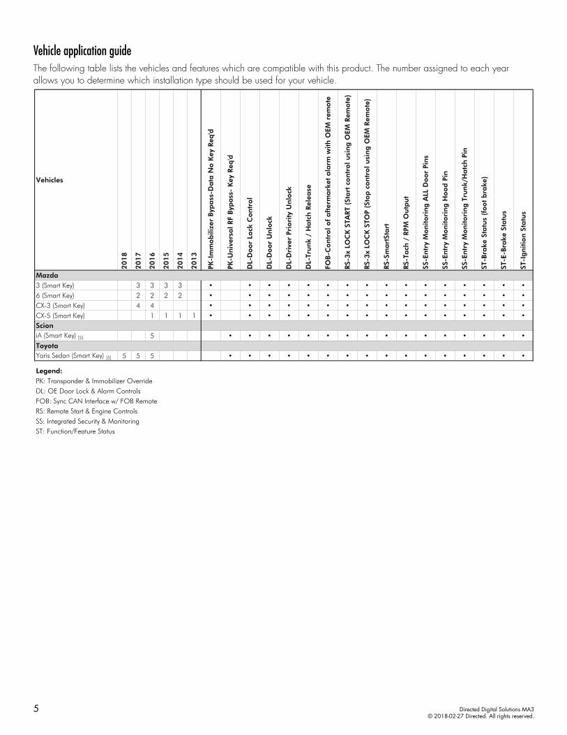
Vehicle application guideThe following table lists the vehicles and features which are compatible with this product. The number assigned to each year allows you to determine which installation type should be used for your vehicle.
Vehicles
20
18
20
17
20
16
20
15
20
14
20
13
PK-I
mm
ob
ilize
r Byp
ass
-Da
ta N
o K
ey R
eq'd
PK-U
niv
ersa
l RF
Byp
ass
- K
ey R
eq'd
DL-
Do
or
Lock
Co
ntr
ol
DL-
Do
or
Un
lock
DL-
Dri
ver
Prio
rity
Un
lock
DL-
Tru
nk
/ H
atc
h R
elea
se
FOB-C
on
tro
l o
f a
fter
ma
rket
ala
rm w
ith
OEM
rem
ote
RS-
3x
LOC
K S
TART
(Sta
rt c
on
tro
l u
sin
g O
EM R
emo
te)
RS-
3x
LOC
K S
TOP
(Sto
p c
on
tro
l u
sin
g O
EM R
emo
te)
RS-
Sma
rtSt
art
RS-
Tach
/ R
PM O
utp
ut
SS-E
ntr
y M
on
ito
rin
g A
LL D
oo
r Pi
ns
SS-E
ntr
y M
on
ito
rin
g H
oo
d P
in
SS-E
ntr
y M
on
ito
rin
g T
run
k/H
atc
h P
in
ST-B
rake
Sta
tus
(fo
ot
bra
ke)
ST-E
-Bra
ke S
tatu
s
ST-I
gn
itio
n S
tatu
s
Mazda3 (Smart Key) 3 3 3 3 • • • • • • • • • • • • • • • •6 (Smart Key) 2 2 2 2 • • • • • • • • • • • • • • • •CX-3 (Smart Key) 4 4 • • • • • • • • • • • • • • • •CX-5 (Smart Key) 1 1 1 1 • • • • • • • • • • • • • • • •ScioniA (Smart Key) [5] 5 • • • • • • • • • • • • • • • •ToyotaYaris Sedan (Smart Key) [5] 5 5 5 • • • • • • • • • • • • • • • •
Legend:PK: Transponder & Immobilizer OverrideDL: OE Door Lock & Alarm ControlsFOB: Sync CAN Interface w/ FOB RemoteRS: Remote Start & Engine ControlsSS: Integrated Security & MonitoringST: Function/Feature Status
5 Directed Digital Solutions MA3© 2018-02-27 Directed. All rights reserved.
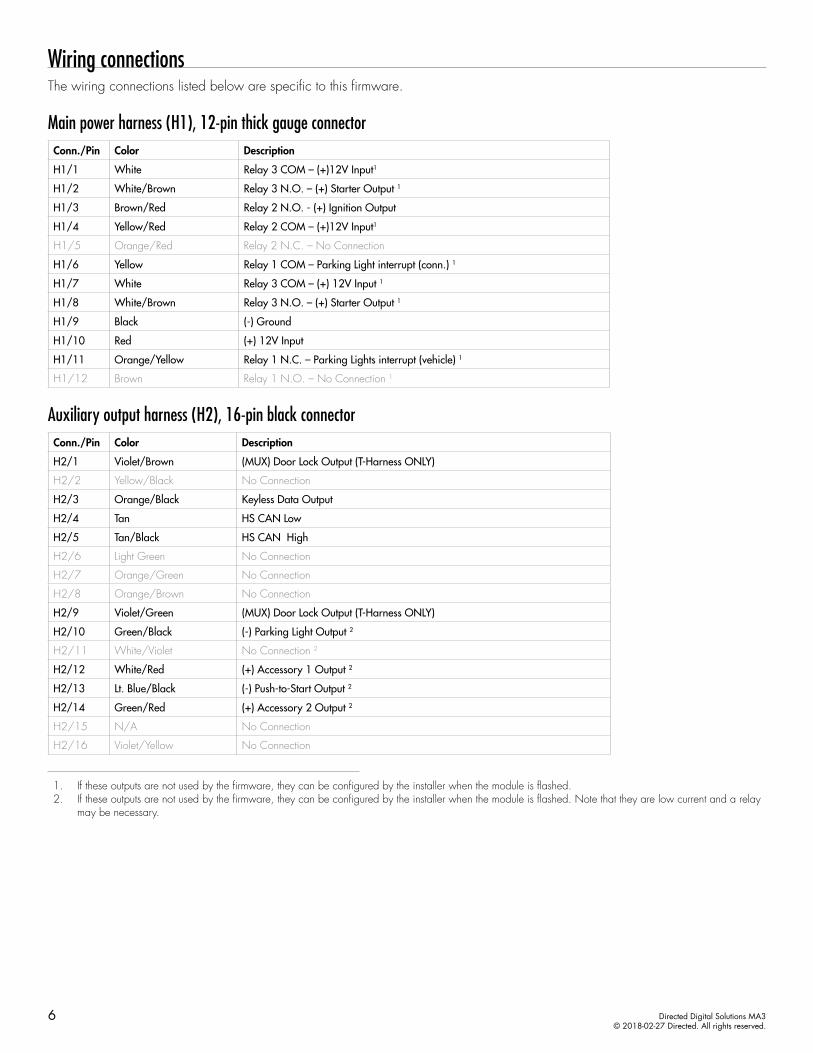
Wiring connectionsThe wiring connections listed below are specific to this firmware.
Main power harness (H1), 12-pin thick gauge connectorConn./Pin Color Description
H1/1 White Relay 3 COM – (+)12V Input1
H1/2 White/Brown Relay 3 N.O. – (+) Starter Output 1
H1/3 Brown/Red Relay 2 N.O. - (+) Ignition Output
H1/4 Yellow/Red Relay 2 COM – (+)12V Input1
H1/5 Orange/Red Relay 2 N.C. – No Connection
H1/6 Yellow Relay 1 COM – Parking Light interrupt (conn.) 1
H1/7 White Relay 3 COM – (+) 12V Input 1
H1/8 White/Brown Relay 3 N.O. – (+) Starter Output 1
H1/9 Black (-) Ground
H1/10 Red (+) 12V Input
H1/11 Orange/Yellow Relay 1 N.C. – Parking Lights interrupt (vehicle) 1
H1/12 Brown Relay 1 N.O. – No Connection 1
Auxiliary output harness (H2), 16-pin black connectorConn./Pin Color Description
H2/1 Violet/Brown (MUX) Door Lock Output (T-Harness ONLY)
H2/2 Yellow/Black No Connection
H2/3 Orange/Black Keyless Data Output
H2/4 Tan HS CAN Low
H2/5 Tan/Black HS CAN High
H2/6 Light Green No Connection
H2/7 Orange/Green No Connection
H2/8 Orange/Brown No Connection
H2/9 Violet/Green (MUX) Door Lock Output (T-Harness ONLY)
H2/10 Green/Black (-) Parking Light Output 2
H2/11 White/Violet No Connection 2
H2/12 White/Red (+) Accessory 1 Output 2
H2/13 Lt. Blue/Black (-) Push-to-Start Output 2
H2/14 Green/Red (+) Accessory 2 Output 2
H2/15 N/A No Connection
H2/16 Violet/Yellow No Connection
1. If these outputs are not used by the firmware, they can be configured by the installer when the module is flashed.2. If these outputs are not used by the firmware, they can be configured by the installer when the module is flashed. Note that they are low current and a relay
may be necessary.
6 Directed Digital Solutions MA3© 2018-02-27 Directed. All rights reserved.

Analog harness (H3), 18-pin white connectorConn./Pin Color Description
H3/1 Lt. Blue/Red No Connection
H3/2 Black/White (-) Parking Brake Input (manual transmission) 2
H3/3 Gray (-) Hood Input 2
H3/4 N/A No Connection
H3/5 Gray/Black (+) Trunk Shunt Input 2
H3/6 Violet/White (AC) Tach Input 2
H3/7 Dark Blue (-) Ignition Interrupt Output1
H3/8 Brown/Black (-) No Connection 1
H3/9 Red/White (-) Trunk Release Output 1
H3/10 White/Green (-) Door Input 2
H3/11 Yellow/Green (+) Door Input 2
H3/12 Blue/Red No Connection
H3/13 Light Blue (-) Trunk Trigger Input 2
H3/14 Pink/Yellow (-) Activation (start) Input
H3/15 Dark Green No Connection 1
H3/16 Brown/White (+) Brake Input 2
H3/17 Brown (+) Siren Output 1
H3/18 Blue/White (-) Key Wrap Output 1
MC501 harness (H4), 8 thick-gauge wires (optional)Conn./Pin Color Description
H4/1 Pink/White (+) Ignition 2/Flex Relay Output 3
H4/2 Red/White (+) Fused (30A) Ignition 2/Flex Relay Input
H4/3 Pink (+) Ignition Output (also input to Yellow in ribbon cable)
H4/4 Red (+) 12 Volt (battery) Input
H4/5 Orange (+) Accessory Output
H4/6 Red (+) 12 Volt (battery) Input
H4/7 Green Starter Input (from key switch) 4
H4/8 Violet (+) Starter Output (to starter)
1. If these outputs are not used by the firmware, they can be configured by the installer when the module is flashed. Note that they are low current and a relay may be necessary.
2. These connections are only required if the corresponding statuses are not supported by the firmware. See "Vehicle application guide" on page 5 for a list of compatible features.
7 Directed Digital Solutions MA3© 2018-02-27 Directed. All rights reserved.
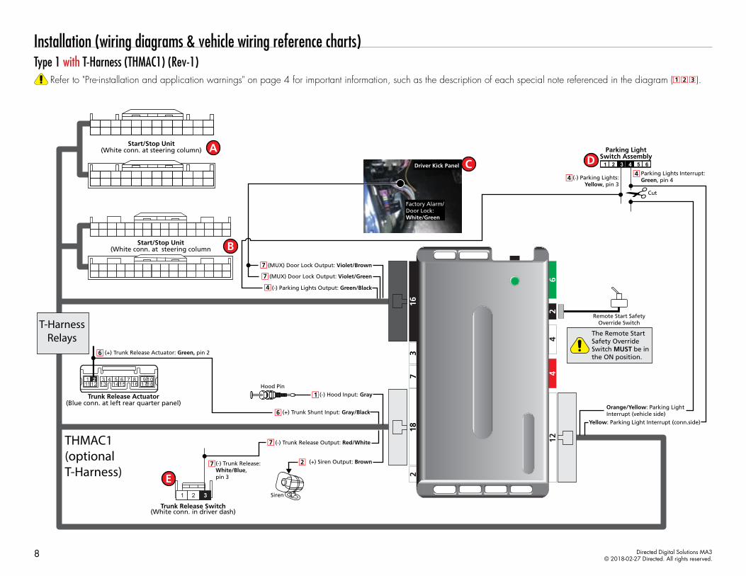
Installation (wiring diagrams & vehicle wiring reference charts)Type 1 with T-Harness (THMAC1) (Rev-1)
Refer to "Pre-installation and application warnings" on page 4 for important information, such as the description of each special note referenced in the diagram ( ).
(-) Trunk Release Output: Red/White
(+) Trunk Shunt Input: Gray/Black
Siren
The Remote Start Safety Override Switch MUST be in the ON position.
Remote Start SafetyOverride Switch
Hood Pin(-) Hood Input: Gray
(+) Siren Output: Brown
(-) Parking Lights Output: Green/Black
(MUX) Door Lock Output: Violet/Green
(MUX) Door Lock Output: Violet/Brown
Factory Alarm/Door Lock:White/Green
Driver Kick Panel
(-) Trunk Release: White/Blue, pin 3
(+) Trunk Release Actuator: Green, pin 2
Orange/Yellow: Parking Light Interrupt (vehicle side)
Parking LightSwitch Assembly
654321Parking Lights Interrupt:Green, pin 4(-) Parking Lights:
Yellow, pin 3
Yellow: Parking Light Interrupt (conn.side)
132 3
1112 18109
1786 7
1454
16151
Start/Stop Unit(White conn. at steering column)
Cut
1 2 3
THMAC1(optionalT-Harness)
Start/Stop Unit(White conn. at steering column
T-HarnessRelays
Trunk Release Switch(White conn. in driver dash)
Trunk Release Actuator(Blue conn. at left rear quarter panel)
8 Directed Digital Solutions MA3© 2018-02-27 Directed. All rights reserved.

Type 1Refer to "Pre-installation and application warnings" on page 4 for important information, such as the description of each special note referenced in the diagram ( ).
(-) PTS: Green/White or Lt. Green/Red, pin 20
(+) Ign. 2 Interrupt: Gray/Red, pin 3
Optional
Siren
The Remote Start Safety Override Switch MUST be in the ON position.
Remote Start SafetyOverride Switch
Hood Pin(-) Hood Input: Gray: 3
(+) Siren Output: Brown: 17
HS CAN Low: Tan: 4
HS CAN High: Tan/Black: 5
(-) Push-to-Start Output: Lt. Blue/Black: 13
(+) Accessory 2 Output: Green/Red: 14
(-) Parking Lights Output: Green/Black: 10
(+) Accessory 1 Output: White/Red: 12
24 131415161718192021222312 1234567891011
(+) Starter:Brown/Black,pin 23
(+) Ignition:Lt. Green/Red,
pin 10
HS CAN Low: Red/Yellow, pin 8
HS CAN High: White/Black, pin 7
(+) Accessory 1:Yellow/Green, pin 2
(+) Accessory 2:Brown/Red, pin 14
10: Red: (+) 12V Input
2 & 8 : White/Brown: (+) Starter Output
1 & 7 : White: (+) 12V Input
3 : Brown/Red: (+) Ignition Output
4 : Yellow/Red: (+) 12V Input
11: Orange/Yellow: Parking Light Interrupt (vehicle side)
9: Black: (-) Ground
Parking LightSwitch Assembly
1
654321Parking Lights (cut):Green, pin 4(-) Parking Lights:
Yellow, pin 3
(+) 12V:White,pin 1
6 : Yellow: Parking Light Interr. (conn. side)
1632 31 30 29 28 27 26 25 24 23 22 21 20 19 18
12456789101112131415
30
86 8587
87a30
86 8587
87a
(+)12V
317
Cut
Cut
Cut
(-) Ignition Interrupt Output: Dark Blue: 7
Start/Stop Unit(White conn. at steering column)
Start/Stop Unit(White conn. at steering column)
Fuse Box(White conn.
at drivers kick)
Keyless Data Output: Orange/Black: 3
Keyless Data:Green/Orange, pin 9
(+) Ign. 3 Interrupt:Violet, pin 17
132 3
1112 18109
1786 7
1454
16151
(+) Trunk Shunt Input: Gray/Black: 5
(+) Trunk Release Actuator: Green, pin 2
Trunk Release Actuator(Blue conn. at left rear quarter panel)
9 Directed Digital Solutions MA3© 2018-02-27 Directed. All rights reserved.

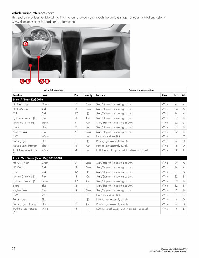
Vehicle wiring reference chartThis section provides vehicle wiring information to guide you through the various stages of your installation. Refer to www.directechs.com for additional information.
Wire Information Connector Information
Function Color Pin Polarity Location Color Pins Ref.
Mazda CX-5 (Smart Key) 2013-2016
HS CAN High White/Black 7 Data Start/Stop unit in steering column. White 24 A
HS CAN Low Red/Yellow 8 Data Start/Stop unit in steering column. White 24 A
Accessory 1 Yellow/Green 2 (+) Start/Stop unit in steering column. White 24 A
Accessory 2 Brown/Red 14 (+) Start/Stop unit in steering column. White 24 A
Ignition 1 Lt. Green/Red 10 (+) Start/Stop unit in steering column. White 24 A
Starter Brown/Black 23 (+) Start/Stop unit in steering column. White 24 A
PTS 1 Green/White or Lt. Green/Red 20 (-) Start/Stop unit in steering column. White 32 B
Ignition 2 Interrupt [3] Gray/Red 3 Cut Start/Stop unit in steering column. White 32 B
Ignition 3 Interrupt [3] Violet 17 Cut Start/Stop unit in steering column. White 32 B
Keyless Data Green/Orange 9 Data Start/Stop unit in steering column White 32 B
12V White 1 (+) Fusebox in driver kick. White 1 C
Parking Lights Yellow 3 (-) Parking light assembly switch. White 6 D
Parking Lights Interrupt Green 4 Cut Parking light assembly switch. White 6 D
Door Lock [6] White/Green 12 MUX Driver kick, door harness. White 32 C
Trunk Release Actuator [6]
Green 2 (+) BCM in left rear quarter panel. Blue 18 -
Trunk Release [7] White/Blue 3 (-) Trunk release switch. White 3 E
10 Directed Digital Solutions MA3© 2018-02-27 Directed. All rights reserved.

Type 2 with T-Harness (THMAC1) (Rev-1)Refer to "Pre-installation and application warnings" on page 4 for important information, such as the description of each special note referenced in the diagram ( ).
(-) Trunk Release Output: Red/White
(+) Trunk Shunt Input: Gray/Black
Siren
The Remote Start Safety Override Switch MUST be in the ON position.
Remote Start SafetyOverride Switch
Hood Pin(-) Hood Input: Gray
(+) Siren Output: Brown
(-) Parking Lights Output: Green/Black
(MUX) Door Lock Output: Violet/Green
(MUX) Door Lock Output: Violet/Brown
Factory Alarm/Door Lock:White/Green
Driver Kick Panel
(-) Trunk Release: Green/Red, pin 1
(+) Trunk Release Actuator: Green or Brown, pin 2
Orange/Yellow: Parking Light Interrupt (vehicle side)
Parking LightSwitch Assembly
654321Parking Lights Interrupt:Green, pin 4(-) Parking Lights:
Yellow, pin 3
Yellow: Parking Light Interrupt (conn.side)
132 3
1112 18109
1786 7
1454
16151
Start/Stop Unit(White conn. at steering column)
Cut
THMAC1(optionalT-Harness)
Start/Stop Unit(White conn. at steering column
T-HarnessRelays
Trunk Release Actuator(Blue conn. at left rear quarter panel)
Trunk Release Switch1 2 3 4
11 Directed Digital Solutions MA3© 2018-02-27 Directed. All rights reserved.
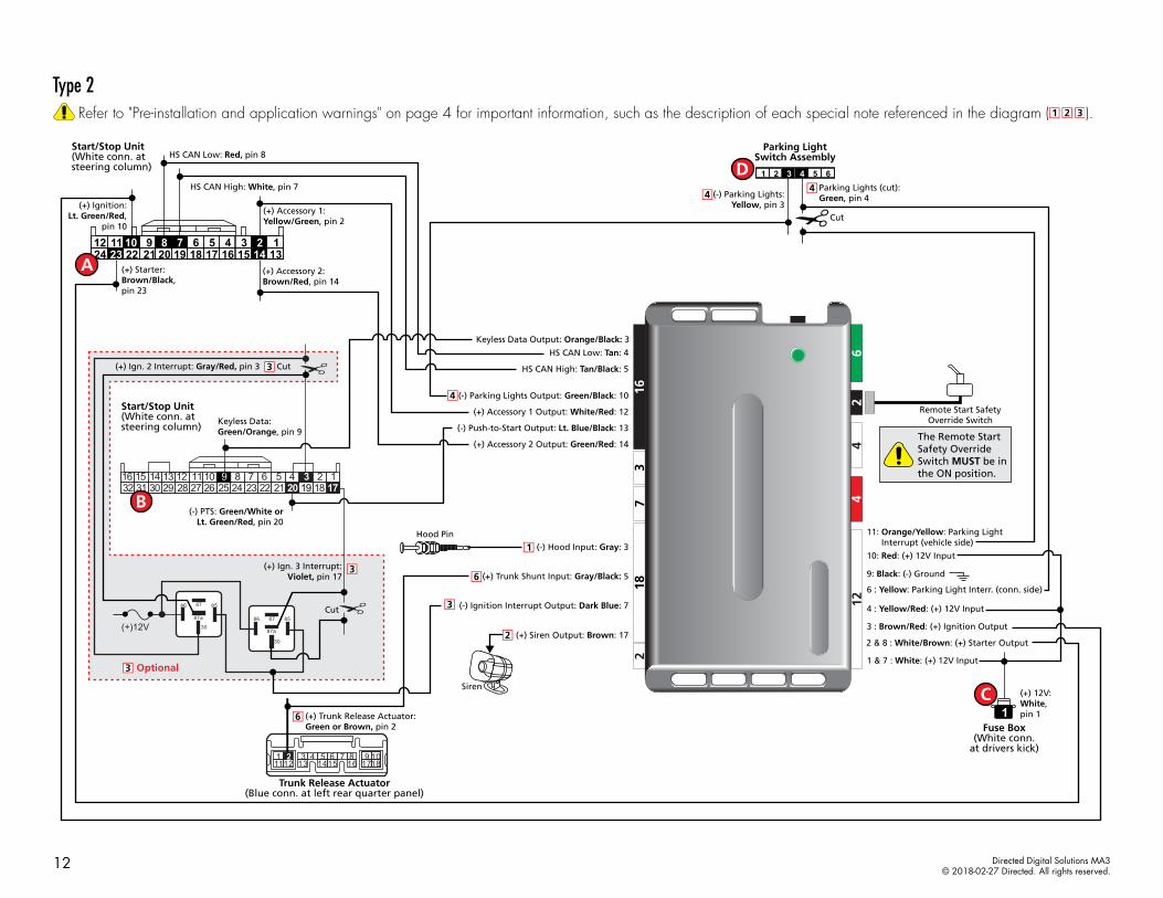
Type 2 Refer to "Pre-installation and application warnings" on page 4 for important information, such as the description of each special note referenced in the diagram ( ).
(-) PTS: Green/White or Lt. Green/Red, pin 20
(+) Ign. 2 Interrupt: Gray/Red, pin 3
Optional
(-) Ignition Interrupt Output: Dark Blue: 7
Siren
The Remote Start Safety Override Switch MUST be in the ON position.
Remote Start SafetyOverride Switch
Hood Pin(-) Hood Input: Gray: 3
(+) Siren Output: Brown: 17
HS CAN Low: Tan: 4
HS CAN High: Tan/Black: 5
(-) Push-to-Start Output: Lt. Blue/Black: 13
(+) Accessory 2 Output: Green/Red: 14
(-) Parking Lights Output: Green/Black: 10
(+) Accessory 1 Output: White/Red: 12
24 131415161718192021222312 1234567891011
(+) Starter:Brown/Black,pin 23
(+) Ignition:Lt. Green/Red,
pin 10
HS CAN Low: Red, pin 8
HS CAN High: White, pin 7
(+) Accessory 1:Yellow/Green, pin 2
(+) Accessory 2:Brown/Red, pin 14
10: Red: (+) 12V Input
2 & 8 : White/Brown: (+) Starter Output
1 & 7 : White: (+) 12V Input
3 : Brown/Red: (+) Ignition Output
4 : Yellow/Red: (+) 12V Input
11: Orange/Yellow: Parking Light Interrupt (vehicle side)
9: Black: (-) Ground
Parking LightSwitch Assembly
1
654321Parking Lights (cut):Green, pin 4(-) Parking Lights:
Yellow, pin 3
(+) 12V:White,pin 1
6 : Yellow: Parking Light Interr. (conn. side)
1632 31 30 29 28 27 26 25 24 23 22 21 20 19 18
12456789101112131415
30
86 8587
87a30
86 8587
87a
(+)12V
317
Cut
Cut
Cut
Start/Stop Unit(White conn. at steering column)
Start/Stop Unit(White conn. at steering column)
Fuse Box(White conn.
at drivers kick)
Keyless Data Output: Orange/Black: 3
Keyless Data:Green/Orange, pin 9
(+) Ign. 3 Interrupt:Violet, pin 17
(+) Trunk Release Actuator: Green or Brown, pin 2
132 3
1112 18109
1786 7
1454
16151
(+) Trunk Shunt Input: Gray/Black: 5
Trunk Release Actuator(Blue conn. at left rear quarter panel)
12 Directed Digital Solutions MA3© 2018-02-27 Directed. All rights reserved.
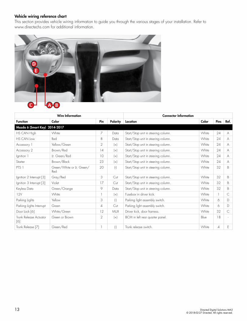
Vehicle wiring reference chartThis section provides vehicle wiring information to guide you through the various stages of your installation. Refer to www.directechs.com for additional information.
Wire Information Connector Information
Function Color Pin Polarity Location Color Pins Ref.
Mazda 6 (Smart Key) 2014-2017
HS CAN High White 7 Data Start/Stop unit in steering column. White 24 A
HS CAN Low Red 8 Data Start/Stop unit in steering column. White 24 A
Accessory 1 Yellow/Green 2 (+) Start/Stop unit in steering column. White 24 A
Accessory 2 Brown/Red 14 (+) Start/Stop unit in steering column. White 24 A
Ignition 1 Lt. Green/Red 10 (+) Start/Stop unit in steering column. White 24 A
Starter Brown/Black 23 (+) Start/Stop unit in steering column. White 24 A
PTS 1 Green/White or Lt. Green/Red
20 (-) Start/Stop unit in steering column. White 32 B
Ignition 2 Interrupt [3] Gray/Red 3 Cut Start/Stop unit in steering column. White 32 B
Ignition 3 Interrupt [3] Violet 17 Cut Start/Stop unit in steering column. White 32 B
Keyless Data Green/Orange 9 Data Start/Stop unit in steering column. White 32 B
12V White 1 (+) Fusebox in driver kick. White 1 C
Parking Lights Yellow 3 (-) Parking light assembly switch. White 6 D
Parking Lights Interrupt Green 4 Cut Parking light assembly switch. White 6 D
Door Lock [6] White/Green 12 MUX Driver kick, door harness. White 32 C
Trunk Release Actuator [6]
Green or Brown 2 (+) BCM in left rear quarter panel. Blue 18 -
Trunk Release [7] Green/Red 1 (-) Trunk release switch. White 4 E
13 Directed Digital Solutions MA3© 2018-02-27 Directed. All rights reserved.

Type 3 with T-Harness (THMAC1) (Rev-1)Refer to "Pre-installation and application warnings" on page 4 for important information, such as the description of each special note referenced in the diagram ( ).
(-) Trunk Release Output: Red/White
(+) Trunk Shunt Input: Gray/Black
Siren
The Remote Start Safety Override Switch MUST be in the ON position.
Remote Start SafetyOverride Switch
Hood Pin(-) Hood Input: Gray
(+) Siren Output: Brown
(-) Parking Lights Output: Green/Black
(MUX) Door Lock Output: Violet/Green
(MUX) Door Lock Output: Violet/Brown
Factory Alarm/Door Lock:Lt. Blue
Driver Kick Panel
(-) Trunk Release: White, pin 1
(+) Trunk Release Actuator: Blue, pin 2
Orange/Yellow: Parking Light Interrupt (vehicle side)
Parking LightSwitch Assembly
654321Parking Lights Interrupt:Green, pin 4(-) Parking Lights:
Yellow, pin 3
Yellow: Parking Light Interrupt (conn.side)
132 3
1112 18109
1786 7
1454
16151
Start/Stop Unit(White conn. at steering column)
Cut
THMAC1(optionalT-Harness)
Start/Stop Unit(White conn. at steering column
T-HarnessRelays
Trunk Release Actuator(Blue conn. at left rear quarter panel)
Trunk Release Switch1 2 3 4
14 Directed Digital Solutions MA3© 2018-02-27 Directed. All rights reserved.
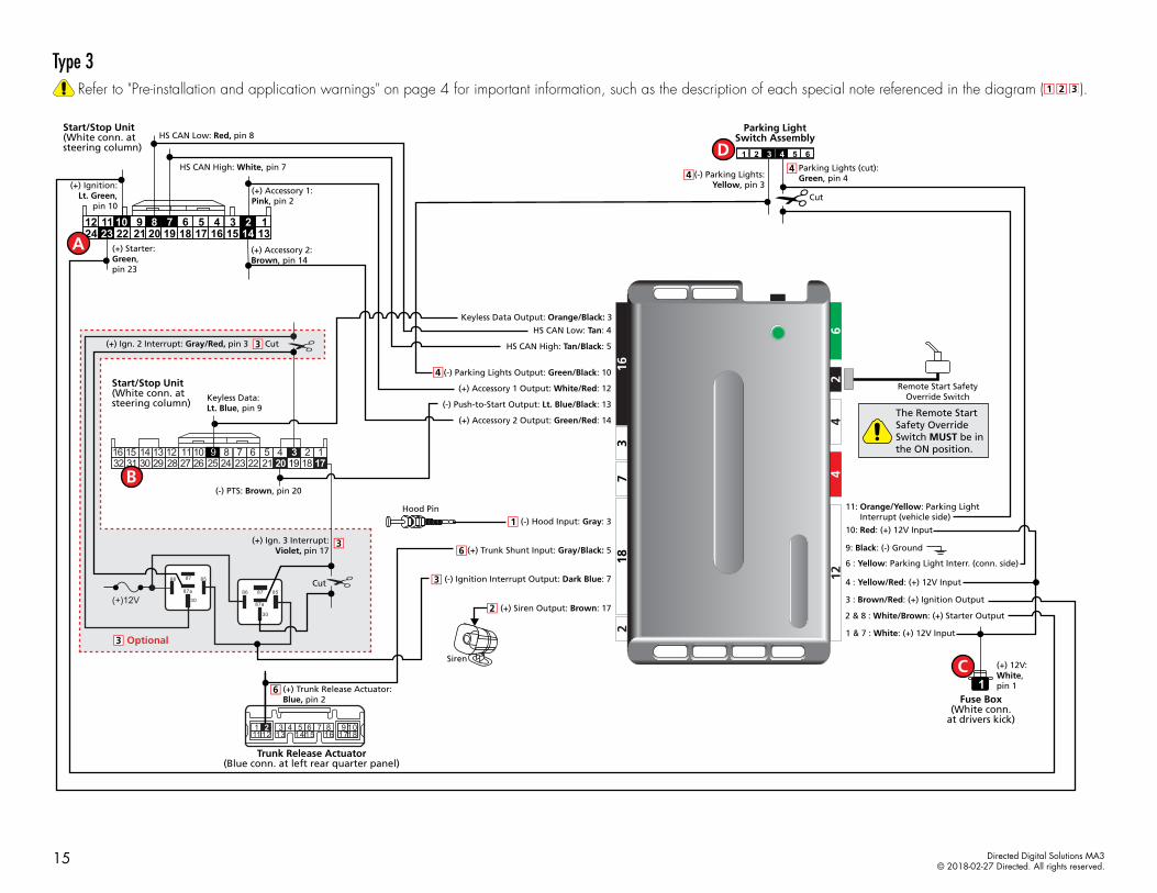
Type 3Refer to "Pre-installation and application warnings" on page 4 for important information, such as the description of each special note referenced in the diagram ( ).
(-) PTS: Brown, pin 20
(+) Ign. 2 Interrupt: Gray/Red, pin 3
Optional
(+) Ign. 3 Interrupt:Violet, pin 17
(-) Ignition Interrupt Output: Dark Blue: 7
Siren
The Remote Start Safety Override Switch MUST be in the ON position.
Remote Start SafetyOverride Switch
Hood Pin(-) Hood Input: Gray: 3
(+) Siren Output: Brown: 17
HS CAN Low: Tan: 4
HS CAN High: Tan/Black: 5
(-) Push-to-Start Output: Lt. Blue/Black: 13
(+) Accessory 2 Output: Green/Red: 14
(-) Parking Lights Output: Green/Black: 10
(+) Accessory 1 Output: White/Red: 12
24 131415161718192021222312 1234567891011
(+) Starter:Green,pin 23
(+) Ignition:Lt. Green,
pin 10
HS CAN Low: Red, pin 8
HS CAN High: White, pin 7
(+) Accessory 1:Pink, pin 2
(+) Accessory 2:Brown, pin 14
10: Red: (+) 12V Input
2 & 8 : White/Brown: (+) Starter Output
1 & 7 : White: (+) 12V Input
3 : Brown/Red: (+) Ignition Output
4 : Yellow/Red: (+) 12V Input
11: Orange/Yellow: Parking Light Interrupt (vehicle side)
9: Black: (-) Ground
Parking LightSwitch Assembly
1
654321Parking Lights (cut):Green, pin 4(-) Parking Lights:
Yellow, pin 3
(+) 12V:White,pin 1
6 : Yellow: Parking Light Interr. (conn. side)
1632 31 30 29 28 27 26 25 24 23 22 21 20 19 18
12456789101112131415
30
86 8587
87a30
86 8587
87a
(+)12V
317
Cut
Cut
Cut
Start/Stop Unit(White conn. at steering column)
Start/Stop Unit(White conn. at steering column)
Fuse Box(White conn.
at drivers kick)
Keyless Data Output: Orange/Black: 3
Keyless Data:Lt. Blue, pin 9
(+) Trunk Release Actuator: Blue, pin 2
132 3
1112 18109
1786 7
1454
16151
Trunk Release Actuator(Blue conn. at left rear quarter panel)
(+) Trunk Shunt Input: Gray/Black: 5
15 Directed Digital Solutions MA3© 2018-02-27 Directed. All rights reserved.
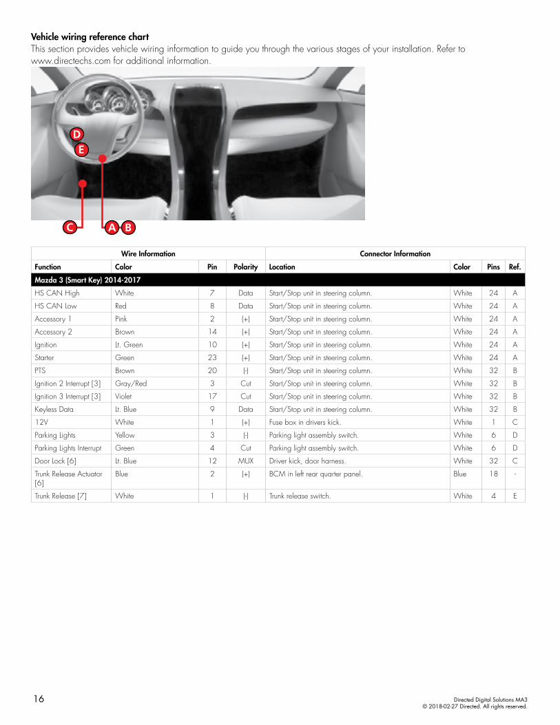
Vehicle wiring reference chartThis section provides vehicle wiring information to guide you through the various stages of your installation. Refer to www.directechs.com for additional information.
Wire Information Connector Information
Function Color Pin Polarity Location Color Pins Ref.
Mazda 3 (Smart Key) 2014-2017
HS CAN High White 7 Data Start/Stop unit in steering column. White 24 A
HS CAN Low Red 8 Data Start/Stop unit in steering column. White 24 A
Accessory 1 Pink 2 (+) Start/Stop unit in steering column. White 24 A
Accessory 2 Brown 14 (+) Start/Stop unit in steering column. White 24 A
Ignition Lt. Green 10 (+) Start/Stop unit in steering column. White 24 A
Starter Green 23 (+) Start/Stop unit in steering column. White 24 A
PTS Brown 20 (-) Start/Stop unit in steering column. White 32 B
Ignition 2 Interrupt [3] Gray/Red 3 Cut Start/Stop unit in steering column. White 32 B
Ignition 3 Interrupt [3] Violet 17 Cut Start/Stop unit in steering column. White 32 B
Keyless Data Lt. Blue 9 Data Start/Stop unit in steering column. White 32 B
12V White 1 (+) Fuse box in drivers kick. White 1 C
Parking Lights Yellow 3 (-) Parking light assembly switch. White 6 D
Parking Lights Interrupt Green 4 Cut Parking light assembly switch. White 6 D
Door Lock [6] Lt. Blue 12 MUX Driver kick, door harness. White 32 C
Trunk Release Actuator [6]
Blue 2 (+) BCM in left rear quarter panel. Blue 18 -
Trunk Release [7] White 1 (-) Trunk release switch. White 4 E
16 Directed Digital Solutions MA3© 2018-02-27 Directed. All rights reserved.
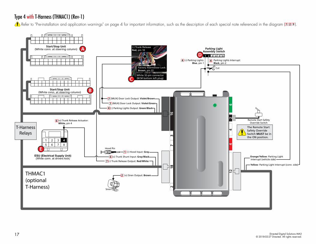
Type 4 with T-Harness (THMAC1) (Rev-1)Refer to "Pre-installation and application warnings" on page 4 for important information, such as the description of each special note referenced in the diagram ( ).
Factory Alarm/Door Lock:Brown, pin 22
White 32-pin connector(BCM bottom left plug)
(-) Trunk ReleaseRed, pin 10
(-) Trunk Release Output: Red/White
(+) Trunk Shunt Input: Gray/Black
Siren
The Remote Start Safety Override Switch MUST be in the ON position.
Remote Start SafetyOverride Switch
Hood Pin(-) Hood Input: Gray
(+) Siren Output: Brown
(-) Parking Lights Output: Green/Black
(MUX) Door Lock Output: Violet/Green
(MUX) Door Lock Output: Violet/Brown
Orange/Yellow: Parking Light Interrupt (vehicle side)
Parking LightAssembly Switch
654321
Parking Lights Interrupt:Black, pin 2
(-) Parking Lights:Blue, pin 1
Yellow: Parking Light Interrupt (conn. side)
(+) Trunk Release Actuator: White, pin 4
1 2 3 45 6 7 8
Cut
THMAC1(optionalT-Harness)
T-HarnessRelays
ESU (Electrical Supply Unit)(White conn. at drivers kick)
Start/Stop Unit(White conn. at steering column)
Start/Stop Unit(White conn. at steering column)
17 Directed Digital Solutions MA3© 2018-02-27 Directed. All rights reserved.
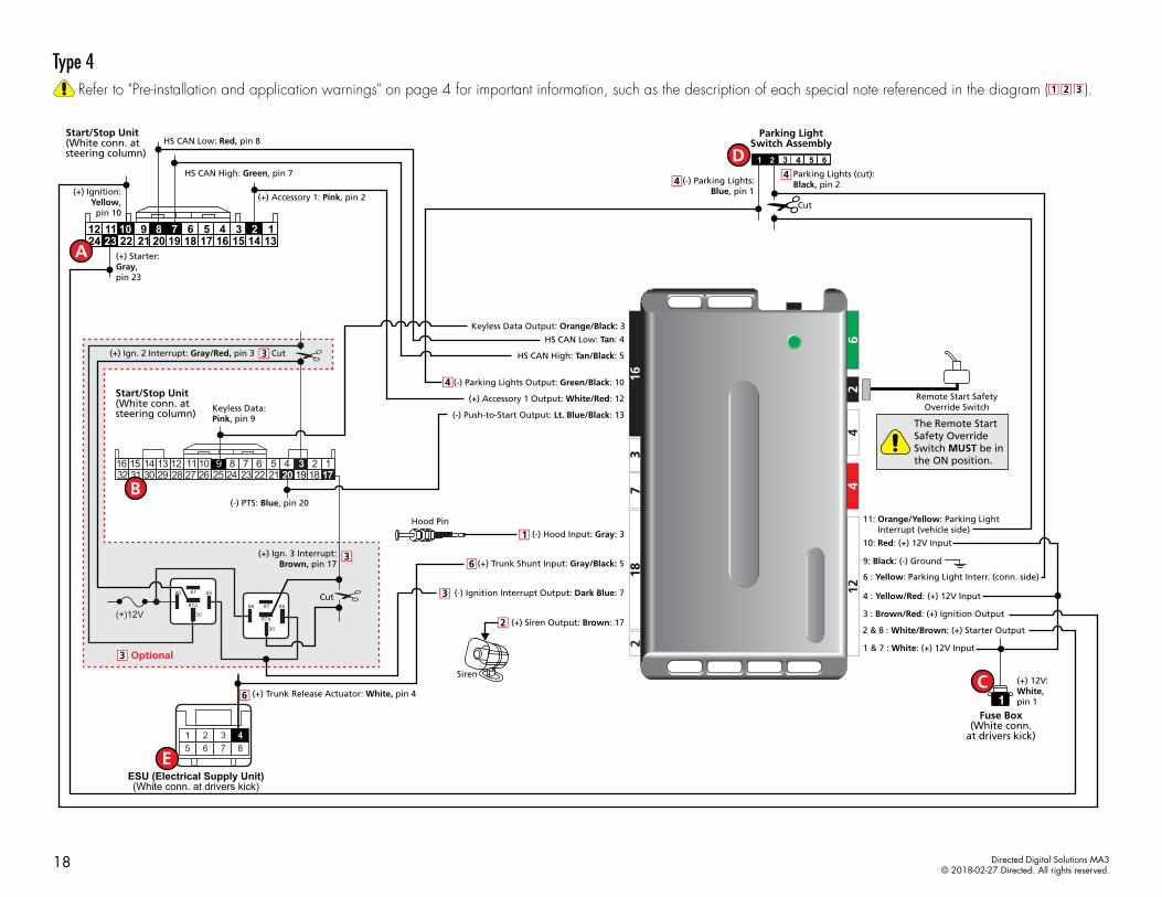
Type 4Refer to "Pre-installation and application warnings" on page 4 for important information, such as the description of each special note referenced in the diagram ( ).
(-) PTS: Blue, pin 20
(+) Ign. 2 Interrupt: Gray/Red, pin 3
Optional
(+) Ign. 3 Interrupt:Brown, pin 17
(-) Ignition Interrupt Output: Dark Blue: 7
Siren
The Remote Start Safety Override Switch MUST be in the ON position.
Remote Start SafetyOverride Switch
Hood Pin(-) Hood Input: Gray: 3
(+) Siren Output: Brown: 17
HS CAN Low: Tan: 4
HS CAN High: Tan/Black: 5
(-) Push-to-Start Output: Lt. Blue/Black: 13
(-) Parking Lights Output: Green/Black: 10
(+) Accessory 1 Output: White/Red: 12
24 131415161718192021222312 1234567891011
(+) Starter:Gray,pin 23
(+) Ignition:Yellow,
pin 10
HS CAN Low: Red, pin 8
HS CAN High: Green, pin 7
(+) Accessory 1: Pink, pin 2
10: Red: (+) 12V Input
2 & 8 : White/Brown: (+) Starter Output
1 & 7 : White: (+) 12V Input
3 : Brown/Red: (+) Ignition Output
4 : Yellow/Red: (+) 12V Input
11: Orange/Yellow: Parking Light Interrupt (vehicle side)
9: Black: (-) Ground
Parking LightSwitch Assembly
1
654321Parking Lights (cut):Black, pin 2(-) Parking Lights:
Blue, pin 1
(+) 12V:White,pin 1
6 : Yellow: Parking Light Interr. (conn. side)
1632 31 30 29 28 27 26 25 24 23 22 21 20 19 18
12456789101112131415
30
86 8587
87a30
86 8587
87a
(+)12V
317
Cut
Cut
Cut
Start/Stop Unit(White conn. at steering column)
Start/Stop Unit(White conn. at steering column)
Fuse Box(White conn.
at drivers kick)
Keyless Data Output: Orange/Black: 3
Keyless Data:Pink, pin 9
(+) Trunk Release Actuator: White, pin 4
1 2 3 45 6 7 8
ESU (Electrical Supply Unit)(White conn. at drivers kick)
(+) Trunk Shunt Input: Gray/Black: 5
18 Directed Digital Solutions MA3© 2018-02-27 Directed. All rights reserved.

Vehicle wiring reference chartThis section provides vehicle wiring information to guide you through the various stages of your installation. Refer to www.directechs.com for additional information.
Wire Information Connector Information
Function Color Pin Polarity Location Color Pins Ref.
Mazda CX-3 (Smart Key) 2016 - 2017
HS CAN High Green 7 Data Start/Stop unit in steering column. White 24 A
HS CAN Low Red 8 Data Start/Stop unit in steering column. White 24 A
Accessory Pink 2 (+) Start/Stop unit in steering column. White 24 A
Ignition Yellow 10 (+) Start/Stop unit in steering column. White 24 A
Starter Gray 23 (+) Start/Stop unit in steering column. White 24 A
PTS Blue 20 (-) Start/Stop unit in steering column. White 32 B
Ignition 2 Interrupt [3] Pink 3 Cut Start/Stop unit in steering column. White 32 B
Ignition 3 Interrupt [3] Brown 17 Cut Start/Stop unit in steering column. White 32 B
Keyless Data Pink 9 Data Start/Stop unit in steering column. White 32 B
12V White 1 (+) Fuse box in drivers kick. White 1 C
Parking Lights Blue 1 (-) Parking light assembly switch. White 6 D
Parking Lights Interrupt Black 2 Cut Parking light assembly switch. White 6 D
Door Lock [6] Brown 22 MUX BCM bottom left plug. White 32 C
Trunk Release Actuator [6]
White 4 (+) ESU (Electrical Supply Unit) in drivers kick panel. White 8 E
Trunk Release [7] Red 10 (-) BCM above driver kick panel. White 32 C
19 Directed Digital Solutions MA3© 2018-02-27 Directed. All rights reserved.

Type 5Refer to "Pre-installation and application warnings" on page 4 for important information, such as the description of each special note referenced in the diagram ( ).
Optional
(-) Ignition Interrupt Output: Dk.Blue: 7
Siren
The Remote Start Safety Override Switch MUST be in the ON position.
Remote Start SafetyOverride Switch
Hood Pin(-) Hood Input: Gray: 3
(+) Siren Output: Brown: 17
HS CAN Low: Tan: 4
HS CAN High: Tan/Black: 5
(-) Push-to-Start Output: Lt. Blue/Black: 13
(-) Parking Lights Output: Green/Black: 10
24 1315161718192021222312 134567891011 2
14
(-) PTS: Red, pin 17
HS CAN Low: Red, pin 8
HS CAN High: Green, pin 7
10: Red: (+) 12V Input
1 & 7: White: (+) 12V Input
2 & 8: White/Brown: (+) Brake Output
11: Orange/Yellow: Parking Light Interrupt (vehicle side)
9: Black: (-) Ground
Parking LightAssembly Switch
1
654321Parking Lights Interrupt:Black, pin 2
(-) ParkingLights:
Blue, pin 1
(+) 12V:White,pin 1
6 : Yellow: Parking Light Interrupt (conn. side)
30
86 8587
87a30
86 8587
87a(+)12V
(+) Brake: Blue, pin 2
Keyless Data: Pink, pin 9
1632 31 30 29 28 27 26 25 24 23 22 21 20 19 18
1456789101112131415 317
2
Cut
Cut
(+) Ign. 2 Interrupt: Pink, pin 3
(+) Ignition 3 Interrupt: Brown, pin 17
Cut
Keyless Data: Pink: 3
Start/Stop Unit(White conn. at steering column)
Start/Stop Unit(White conn. at steering column)
Fuse Box(White conn.
at drivers kick)
(-) Key Wrap Output: Blue/White: 18
1 2 3 45 6 7 8
ESU (Electrical Supply Unit)(White conn. at drivers kick)
(+) Trunk Shunt Input: Gray/Black: 5(+) Trunk Release Actuator: White, pin 4
20 Directed Digital Solutions MA3© 2018-02-27 Directed. All rights reserved.
Vehicle wiring reference chartThis section provides vehicle wiring information to guide you through the various stages of your installation. Refer to www.directechs.com for additional information.
Wire Information Connector Information
Function Color Pin Polarity Location Color Pins Ref.
Scion iA (Smart Key) 2016
HS CAN High Green 7 Data Start/Stop unit in steering column. White 24 A
HS CAN Low Red 8 Data Start/Stop unit in steering column. White 24 A
PTS Red 17 (-) Start/Stop unit in steering column. White 24 A
Ignition 2 Interrupt [3] Pink 3 Cut Start/Stop unit in steering column. White 32 B
Ignition 3 Interrupt [3] Brown 17 Cut Start/Stop unit in steering column. White 32 B
Brake Blue 2 (+) Start/Stop unit in steering column. White 32 B
Keyless Data Pink 9 Data Start/Stop unit in steering column. White 32 B
12V White 1 (+) Fuse box in driver kick. White 1 C
Parking Lights Blue 1 (-) Parking light assembly switch. White 6 D
Parking Lights Interrupt Black 2 Cut Parking light assembly switch. White 6 D
Trunk Release Actuator [6]
White 4 (+) ESU (Electrical Supply Unit) in drivers kick panel. White 8 E
Toyota Yaris Sedan (Smart Key) 2016-2018
HS CAN High Green 7 Data Start/Stop unit in steering column. White 24 A
HS CAN Low Red 8 Data Start/Stop unit in steering column. White 24 A
PTS Red 17 (-) Start/Stop unit in steering column. White 24 A
Ignition 2 Interrupt [3] Pink 3 Cut Start/Stop unit in steering column. White 32 B
Ignition 3 Interrupt [3] Brown 17 Cut Start/Stop unit in steering column. White 32 B
Brake Blue 2 (+) Start/Stop unit in steering column. White 32 B
Keyless Data Pink 9 Data Start/Stop unit in steering column. White 32 B
12V White 1 (+) Fuse box in driver kick. White 1 C
Parking Lights Blue 1 (-) Parking light assembly switch. White 6 D
Parking Lights Interrupt Black 2 Cut Parking light assembly switch. White 6 D
Trunk Release Actuator [6]
White 4 (+) ESU (Electrical Supply Unit) in drivers kick panel. White 8 E
21 Directed Digital Solutions MA3© 2018-02-27 Directed. All rights reserved.
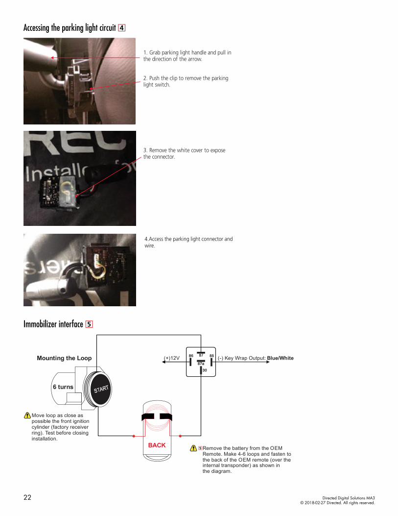
Accessing the parking light circuit
1. Grab parking light handle and pull in the direction of the arrow.
2. Push the clip to remove the parking light switch.
3. Remove the white cover to expose the connector.
4.Access the parking light connector and wire.
Immobilizer interface
(+)12V (-) Key Wrap Output: Blue/White
Move loop as close as possible the front ignition cylinder (factory receiver ring). Test before closing installation.
Remove the battery from the OEM Remote. Make 4-6 loops and fasten to the back of the OEM remote (over the internal transponder) as shown in the diagram.
Mounting the Loop
6 turns
BACK
22 Directed Digital Solutions MA3© 2018-02-27 Directed. All rights reserved.
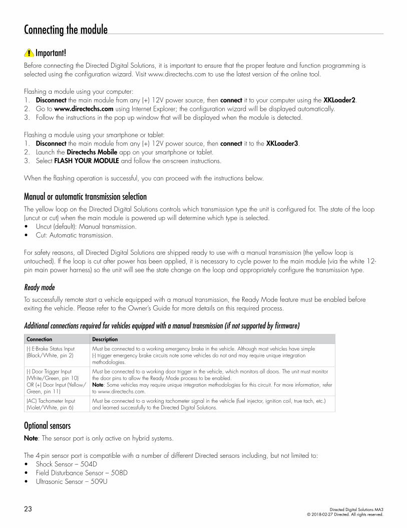
Connecting the module
Important!Before connecting the Directed Digital Solutions, it is important to ensure that the proper feature and function programming is selected using the configuration wizard. Visit www.directechs.com to use the latest version of the online tool.
Flashing a module using your computer:1. Disconnect the main module from any (+) 12V power source, then connect it to your computer using the XKLoader2.2. Go to www.directechs.com using Internet Explorer; the configuration wizard will be displayed automatically.3. Follow the instructions in the pop up window that will be displayed when the module is detected.
Flashing a module using your smartphone or tablet:1. Disconnect the main module from any (+) 12V power source, then connect it to the XKLoader3.2. Launch the Directechs Mobile app on your smartphone or tablet.3. Select FLASH YOUR MODULE and follow the on-screen instructions.
When the flashing operation is successful, you can proceed with the instructions below.
Manual or automatic transmission selectionThe yellow loop on the Directed Digital Solutions controls which transmission type the unit is configured for. The state of the loop (uncut or cut) when the main module is powered up will determine which type is selected.• Uncut (default): Manual transmission.• Cut: Automatic transmission.
For safety reasons, all Directed Digital Solutions are shipped ready to use with a manual transmission (the yellow loop is untouched). If the loop is cut after power has been applied, it is necessary to cycle power to the main module (via the white 12-pin main power harness) so the unit will see the state change on the loop and appropriately configure the transmission type.
Ready modeTo successfully remote start a vehicle equipped with a manual transmission, the Ready Mode feature must be enabled before exiting the vehicle. Please refer to the Owner’s Guide for more details on this required process.
Additional connections required for vehicles equipped with a manual transmission (if not supported by firmware)
Connection Description
(-) E-Brake Status Input (Black/White, pin 2)
Must be connected to a working emergency brake in the vehicle. Although most vehicles have simple (-) trigger emergency brake circuits note some vehicles do not and may require unique integration methodologies.
(-) Door Trigger Input (White/Green, pin 10) OR (+) Door Input (Yellow/Green, pin 11)
Must be connected to a working door trigger in the vehicle, which monitors all doors. The unit must monitor the door pins to allow the Ready Mode process to be enabled.Note: Some vehicles may require unique integration methodologies for this circuit. For more information, refer to www.directechs.com.
(AC) Tachometer Input (Violet/White, pin 6)
Must be connected to a working tachometer signal in the vehicle (fuel injector, ignition coil, true tach, etc.) and learned successfully to the Directed Digital Solutions.
Optional sensorsNote: The sensor port is only active on hybrid systems.
The 4-pin sensor port is compatible with a number of different Directed sensors including, but not limited to:• Shock Sensor – 504D• Field Disturbance Sensor – 508D• Ultrasonic Sensor – 509U
23 Directed Digital Solutions MA3© 2018-02-27 Directed. All rights reserved.
Note: In the case of 508D, power and ground must be hardwired to the vehicle – power and ground should NOT be obtained from the 4-pin sensor port.
Each sensor will have its own instructions, which must be followed for installation and adjustment.
RF SystemsAn RF System consists of one or multiple remotes, a Control Center (antenna), and an antenna cable – various combinations exist. An RF System allows the vehicle owner to control the system with enhanced range. Two-way models are available. Please follow the instructions included with the kit for appropriate installation and programming information.
When flashing the Directed Digital Solutions, make sure to pick the remote you will be using. This way the main module will have the necessary firmware to interact with the remote and Control Center (antenna) combination.
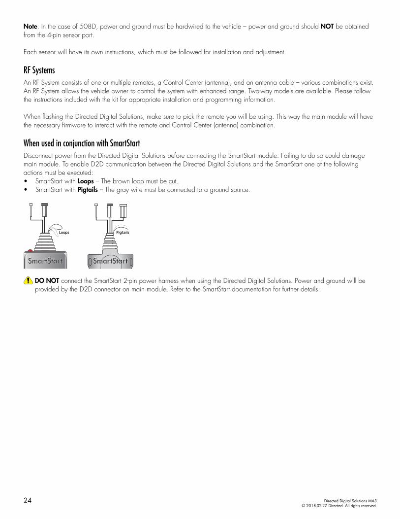
When used in conjunction with SmartStartDisconnect power from the Directed Digital Solutions before connecting the SmartStart module. Failing to do so could damage main module. To enable D2D communication between the Directed Digital Solutions and the SmartStart one of the following actions must be executed:• SmartStart with Loops – The brown loop must be cut. • SmartStart with Pigtails – The gray wire must be connected to a ground source.
Loops Pigtails
DO NOT connect the SmartStart 2-pin power harness when using the Directed Digital Solutions. Power and ground will be provided by the D2D connector on main module. Refer to the SmartStart documentation for further details.
24 Directed Digital Solutions MA3© 2018-02-27 Directed. All rights reserved.

Module programmingRefer to "LED diagnostics and troubleshooting" on page 27 for more information and for troubleshooting purposes.
Installation Types 1-4To connect the module:
1Please ensure that the vehicle is in a safe location and cannot move forward during programming. For vehicles equipped with a manual transmission, make sure the gearshift lever is in the neutral position.
2 Connect all the harnesses to the Directed Digital Solutions, EXCEPT the 12-pin main power harness.
Connect all but the 12-pin harness
3Connect the 12-pin main power harness, and wait until the LED turns ON solid red.Note: To skip the transponder programming and use convenience features only,press the programming button 5 times. The led flashes orange.
Must be connected LAST
&Solid
4Do not press the brake pedal. Press the Push-to-Start (PTS) button twice to turn the ignition ON. The LED will start to flash green.Note: If the transponder programming was skipped, the LED turns ON solid orange for 3 seconds then shuts OFF when programming is done.
FlashesDo NOT depressthe brake pedal
5 Wait for the module to program (it may flash up to 30 seconds). The LED will turn ON green for 3 seconds, then shuts OFF. OffSolid
x3 Secs
6 Turn vehicle ignition OFF once the module is successfully programmed.
7Pair remotes (if applicable). For information on how to pair a specific remote, please refer to its corresponding owner documentation, which can be found inside the product packaging of the complete system or on www.directechs.com.*
Pair remotes*
8 By default, the tachometer is preprogrammed for the vehicle. For instructions on how to program tach, see page 30.
Initialize tachometer
* Your aftermarket remote may differ from the model shown in the illustrations.
25 Directed Digital Solutions MA3© 2018-02-27 Directed. All rights reserved.

Installation Type 5To connect the module:
1Please ensure that the vehicle is in a safe location and cannot move forward during programming. For vehicles equipped with a manual transmission, make sure the gearshift lever is in the neutral position.
2 Connect all the harnesses to the Directed Digital Solutions, EXCEPT the 12-pin main power harness.
Connect all but the 12-pin harness
3 Connect the 12-pin main power harness, and wait until the LED turns ON solid red.Must be connected LAST
&Solid
4 Press the programming button 5 times. The LED will start flashing orange then proceed to the next step. & Flashes
orange
Press 5x
5 Do not press the brake pedal. Press the Push-to-Start (PTS) button twice to turn the ignition ON. Do NOT depress
the brake pedal
6 Wait for the module to program (it may flash up to 30 seconds). The LED will turn ON orange for 3 seconds, then shuts OFF. OffSolid
x3 Secs
7 Press the Push-to-Start (PTS) button once to turn vehicle ignition OFF once the module is suc-cessfully programmed.
8Pair remotes (if applicable). For information on how to pair a specific remote, please refer to its corresponding owner documentation, which can be found inside the product packaging of the complete system or on www.directechs.com.*
Pair remotes*
9 By default, the tachometer is preprogrammed for the vehicle. For instructions on how to program tach, see page 30.
Initialize tachometer
You have successfully completed the module programming sequence.* Your aftermarket remote may differ from the model shown in the illustrations.
26 Directed Digital Solutions MA3© 2018-02-27 Directed. All rights reserved.
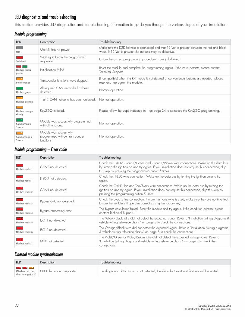
LED diagnostics and troubleshootingThis section provides LED diagnostics and troubleshooting information to guide you through the various stages of your installation.
Module programming
LED Description Troubleshooting
OffModule has no power. Make sure the D2D harness is connected and that 12 Volt is present between the red and black
wires. If 12 Volt is present, the module may be defective.
Solid red
Waiting to begin the programming sequence. Ensure the correct programming procedure is being followed.
Flashes red & green
Initialization failed. Reset the module and complete the programming again. If the issue persists, please contact Technical Support.
Solid orangeTransponder functions were skipped. (If compatible) when the RXT mode is not desired or convenience features are needed, please
reset and reprogram the module.
Flashes green
All required CAN networks has been detected. Normal operation.
Flashes orange1 of 2 CAN networks has been detected. Normal operation.
Flashes orange slowly
Key2GO initiated. Please follow the steps indicated in "" on page 24 to complete the Key2GO programming.
Solid green x 3 secs
Module was successfully programmed with all functions. Normal operation.
Solid orange x 3 secs
Module was successfullyprogrammed without transponder functions.
Normal operation.
Module programming – Error codes
LED Description Troubleshooting
Flashes red x 1CAN2 not detected.
Check the CAN2 Orange/Green and Orange/Brown wire connections. Wake up the data bus by turning the ignition on and try again. If your installation does not require this connection, skip this step by pressing the programming button 5 times.
Flashes red x 1J1850 not detected. Check the J1850 wire connection. Wake up the data bus by turning the ignition on and try
again.
Flashes red x 2CAN1 not detected.
Check the CAN1 Tan and Tan/Black wire connections. Wake up the data bus by turning the ignition on and try again. If your installation does not require this connection, skip this step by pressing the programming button 5 times.
Flashes red x 3Bypass data not detected. Check the bypass line connection. If more than one wire is used, make sure they are not inverted.
Ensure the vehicle still operates correctly using the factory key.
Flashes red x 4Bypass processing error. The bypass calculation failed. Reset the module and try again. If the condition persists, please
contact Technical Support.
Flashes red x 5ISO 1 not detected. The Yellow/Black wire did not detect the expected signal. Refer to "Installation (wiring diagrams &
vehicle wiring reference charts)" on page 8 to check the connections.
Flashes red x 6ISO 2 not detected. The Orange/Black wire did not detect the expected signal. Refer to "Installation (wiring diagrams
& vehicle wiring reference charts)" on page 8 to check the connections.
Flashes red x 7MUX not detected.
The Violet/Green or Violet/Brown wire did not detect the expected voltage value. Refer to "Installation (wiring diagrams & vehicle wiring reference charts)" on page 8 to check the connections.
External module synchronization
LED Description Troubleshooting
(Flashes red, red, then orange) x 10
OBDII feature not supported. The diagnostic data bus was not detected, therefore the SmartStart features will be limited.
27 Directed Digital Solutions MA3© 2018-02-27 Directed. All rights reserved.
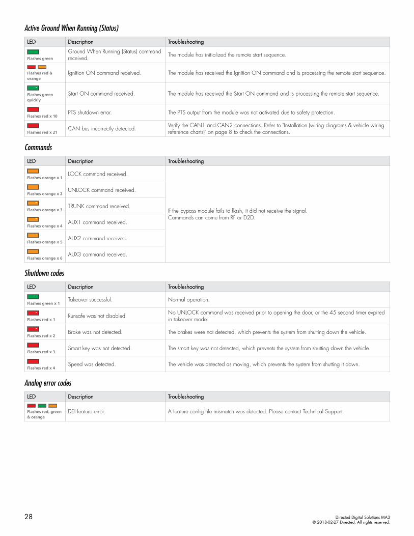
Active Ground When Running (Status)
LED Description Troubleshooting
Flashes green
Ground When Running (Status) command received. The module has initialized the remote start sequence.
Flashes red & orange
Ignition ON command received. The module has received the Ignition ON command and is processing the remote start sequence.
Flashes green quickly
Start ON command received. The module has received the Start ON command and is processing the remote start sequence.
Flashes red x 10PTS shutdown error. The PTS output from the module was not activated due to safety protection.
Flashes red x 21CAN bus incorrectly detected. Verify the CAN1 and CAN2 connections. Refer to "Installation (wiring diagrams & vehicle wiring
reference charts)" on page 8 to check the connections.
Commands
LED Description Troubleshooting
Flashes orange x 1LOCK command received.
If the bypass module fails to flash, it did not receive the signal. Commands can come from RF or D2D.
Flashes orange x 2UNLOCK command received.
Flashes orange x 3TRUNK command received.
Flashes orange x 4AUX1 command received.
Flashes orange x 5AUX2 command received.
Flashes orange x 6AUX3 command received.
Shutdown codes
LED Description Troubleshooting
Flashes green x 1Takeover successful. Normal operation.
Flashes red x 1Runsafe was not disabled. No UNLOCK command was received prior to opening the door, or the 45 second timer expired
in takeover mode.
Flashes red x 2Brake was not detected. The brakes were not detected, which prevents the system from shutting down the vehicle.
Flashes red x 3Smart key was not detected. The smart key was not detected, which prevents the system from shutting down the vehicle.
Flashes red x 4Speed was detected. The vehicle was detected as moving, which prevents the system from shutting it down.
Analog error codes
LED Description Troubleshooting
Flashes red, green & orange
DEI feature error. A feature config file mismatch was detected. Please contact Technical Support.
28 Directed Digital Solutions MA3© 2018-02-27 Directed. All rights reserved.
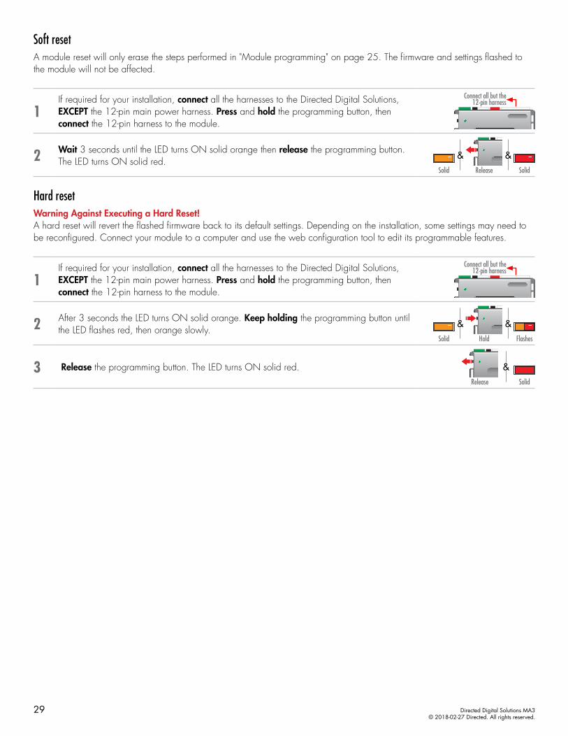
Soft resetA module reset will only erase the steps performed in "Module programming" on page 25. The firmware and settings flashed to the module will not be affected.
1If required for your installation, connect all the harnesses to the Directed Digital Solutions, EXCEPT the 12-pin main power harness. Press and hold the programming button, then connect the 12-pin harness to the module.
Connect all but the 12-pin harness
2 Wait 3 seconds until the LED turns ON solid orange then release the programming button. The LED turns ON solid red.
&&ReleaseSolid Solid
Hard resetWarning Against Executing a Hard Reset! A hard reset will revert the flashed firmware back to its default settings. Depending on the installation, some settings may need to be reconfigured. Connect your module to a computer and use the web configuration tool to edit its programmable features.
1If required for your installation, connect all the harnesses to the Directed Digital Solutions, EXCEPT the 12-pin main power harness. Press and hold the programming button, then connect the 12-pin harness to the module.
Connect all but the 12-pin harness
2 After 3 seconds the LED turns ON solid orange. Keep holding the programming button until the LED flashes red, then orange slowly.
HoldSolid Flashes
&&
3 Release the programming button. The LED turns ON solid red.Release
&Solid
29 Directed Digital Solutions MA3© 2018-02-27 Directed. All rights reserved.

Learning the Tach (not needed with Virtual Tach)Tach comes preprogrammed, therefore learning is not required; however, it can be readjusted with the following operations:1. Start the vehicle using the key. 2. Within 5 seconds, press and hold the Control Center (antenna) or the main module programming button, until the LED on the
Control Center (antenna) or the main module turns ON solid.3. Release the button. The tachometer value is now stored in memory.
If the LED does not turn ON solid, find an alternate tach source.
Note: When the tachometer is programmed, the main module automatically enters the Tachometer engine checking mode.
Initializing Virtual Tach (not needed with hardwired or data tach applications)To program Virtual Tach:1. After the install is complete, remote start the engine. The programming operation may require 3 cranks of the starter before
the engine starts and runs. Do not turn off the remote start if this happens, it is a normal programming operation.2. Once the engine begins running, let it run for at least 30 seconds.3. Using the Remote, send the Remote start command to turn remote start off. Virtual Tach is programmed. To reset Virtual Tach, a
module reset must be done.
Note: Virtual Tach cannot be used in Manual Transmission Mode. It is also not recommended for diesel trucks.
Virtual Tach handles disengaging the starter motor during remote starting – it does not address over-rev. If the customer wants to have the over-rev protection capability, the tach wire or data tach must be used.
Important! After successfully learning Virtual Tach, a small minority of vehicle starters may over crank or under crank during remote start. Use the VirtualTach Fine tune feature in the configuration wizard to adjust the starter output time in 50mS increments to compensate for such an occurrence.
30 Directed Digital Solutions MA3© 2018-02-27 Directed. All rights reserved.
Limited lifetime consumer warrantyDirected Electronics. (“Directed”) promises to the original purchaser to repair or replace (at Directed’s election) with a comparable reconditioned model any Directed unit (hereafter the “unit”), excluding without limitation the siren, the remote transmitters, the associated sensors and accessories, which proves to be defective in workmanship or material under reasonable use during the lifetime of the vehicle provided the following conditions are met: the unit was purchased from an authorized Directed dealer, the unit was professionally installed and serviced by an authorized Directed dealer; the unit will be professionally reinstalled in the vehicle in which it was originally installed by an authorized Directed dealer; and the unit is returned to Directed, shipping prepaid with a legible copy of the bill of sale or other dated proof of purchase bearing the following information: consumer’s name, telephone number and address; the authorized dealers name, telephone number and address; complete product description, including accessories; the year, make and model of the vehicle; vehicle license number and vehicle identification number. All components other than the unit, including without limitation the siren, the remote transmitters and the associated sensors and accessories, carry a one-year warranty from the date of purchase of the same. ALL PRODUCTS RECEIVED BY DIRECTED FOR WARRANTY REPAIR WITHOUT PROOF OF PURCHASE FROM AN AUTHORIZED DEALER WILL BE DENIED. This warranty is non-transferable and is automatically void if: the unit’s date code or serial number is defaced, missing or altered; the unit has been modified or used in a manner contrary to its intended purpose; the unit has been damaged by accident, unreasonable use, neglect, improper service, installation or other causes not arising out of defects in materials or construction. The warranty does not cover damage to the unit caused by installation or removal of the unit. Directed, in its sole discretion, will determine what constitutes excessive damage and may refuse the return of any unit with excessive damage. TO THE MAXIMUM EXTENT ALLOWED BY LAW, ALL WARRANTIES, INCLUDING BUT NOT LIMITED TO EXPRESS WARRANTY, IMPLIED WARRANTY, WARRANTY OF MERCHANTABILITY, FITNESS FOR PARTICULAR PURPOSE AND WARRANTY OF NON-INFRINGEMENT OF INTELLECTUAL PROPERTY, ARE EXPRESSLY EXCLUDED; AND DIRECTED NEITHER ASSUMES NOR AUTHORIZES ANY PERSON OR ENTITY TO ASSUME FOR IT ANY DUTY, OBLIGATION OR LIABILITY IN CONNECTION WITH ITS PRODUCTS. DIRECTED DISCLAIMS AND HAS ABSOLUTELY NO LIABILITY FOR ANY AND ALL ACTS OF THIRD PARTIES INCLUDING ITS AUTHORIZED DEALERS OR INSTALLERS. DIRECTED SECURITY SYSTEMS, INCLUDING THIS UNIT, ARE DETERRENTS AGAINST POSSIBLE THEFT. DIRECTED IS NOT OFFERING A GUARANTEE OR INSURANCE AGAINST VANDALISM, DAMAGE OR THEFT OF THE AUTOMOBILE, ITS PARTS OR CONTENTS; AND HEREBY EXPRESSLY DISCLAIMS ANY LIABILITY WHATSOEVER, INCLUDING WITHOUT LIMITATION, LIABILITY FOR THEFT, DAMAGE AND/OR VANDALISM. THIS WARRANTY DOES NOT COVER LABOR COSTS FOR MAINTENANCE, REMOVAL OR REINSTALLATION OF THE UNIT OR ANY CONSEQUENTIAL DAMAGES OF ANY KIND. IN THE EVENT OF A CLAIM OR A DISPUTE INVOLVING DIRECTED OR ITS SUBSIDIARY, THE VENUE SHALL BE SAN DIEGO COUNTY IN THE STATE OF CALIFORNIA. CALIFORNIA STATE LAWS AND APPLICABLE FEDERAL LAWS SHALL APPLY AND GOVERN THE DISPUTE. THE MAXIMUM RECOVERY UNDER ANY CLAIM AGAINST DIRECTED SHALL BE STRICTLY LIMITED TO THE AUTHORIZED DIRECTED DEALER’S PURCHASE PRICE OF THE UNIT. DIRECTED SHALL NOT BE RESPONSIBLE FOR ANY DAMAGES WHATSOEVER, INCLUDING BUT NOT LIMITED TO, ANY CONSEQUENTIAL DAMAGES, INCIDENTAL DAMAGES, DAMAGE TO VEHICLE, DAMAGES FOR THE LOSS OF TIME, LOSS OF EARNINGS, COMMERCIAL LOSS, LOSS OF ECONOMIC OPPORTUNITY AND THE LIKE. NOTWITHSTANDING THE ABOVE, THE MANUFACTURER DOES OFFER A LIMITED WARRANTY TO REPLACE OR REPAIR THE CONTROL MODULE SUBJECT TO THE CONDITIONS AS DESCRIBED HEREIN. THIS WARRANTY IS VOID IF THE UNIT HAS NOT BEEN PURCHASED FROM DIRECTED, OR AN AUTHORIZED DIRECTED DEALER, OR IF THE UNIT HAS BEEN DAMAGED BY ACCIDENT, UNREASONABLE USE, NEGLIGENCE, ACTS OF GOD, NEGLECT, IMPROPER SERVICE, OR OTHER CAUSES NOT ARISING OUT OF DEFECT IN MATERIALS OR CONSTRUCTION.
Some states do not allow limitations on how long an implied warranty will last or the exclusion or limitation of incidental or consequential damages. This warranty gives you specific legal rights and you may also have other rights that vary from State to State.
This warranty is only valid for sale of product(s) within the United States of America and in Canada. Product(s) sold outside of the United States of America or Canada are sold “AS-IS” and shall have NO WARRANTY, express or implied.
For further details relating to warranty information of Directed products, please visit the support section of Directed’s website at: www.directed.com.
This product may be covered by a Guaranteed Protection Plan (“GPP”). See your authorized Directed dealer for details of the plan or call Directed Customer Service at 1-800-876-0800.
(920-10011-01 2011-06)
31 Directed Digital Solutions MA3© 2018-02-27 Directed. All rights reserved.
Quick Reference Guide
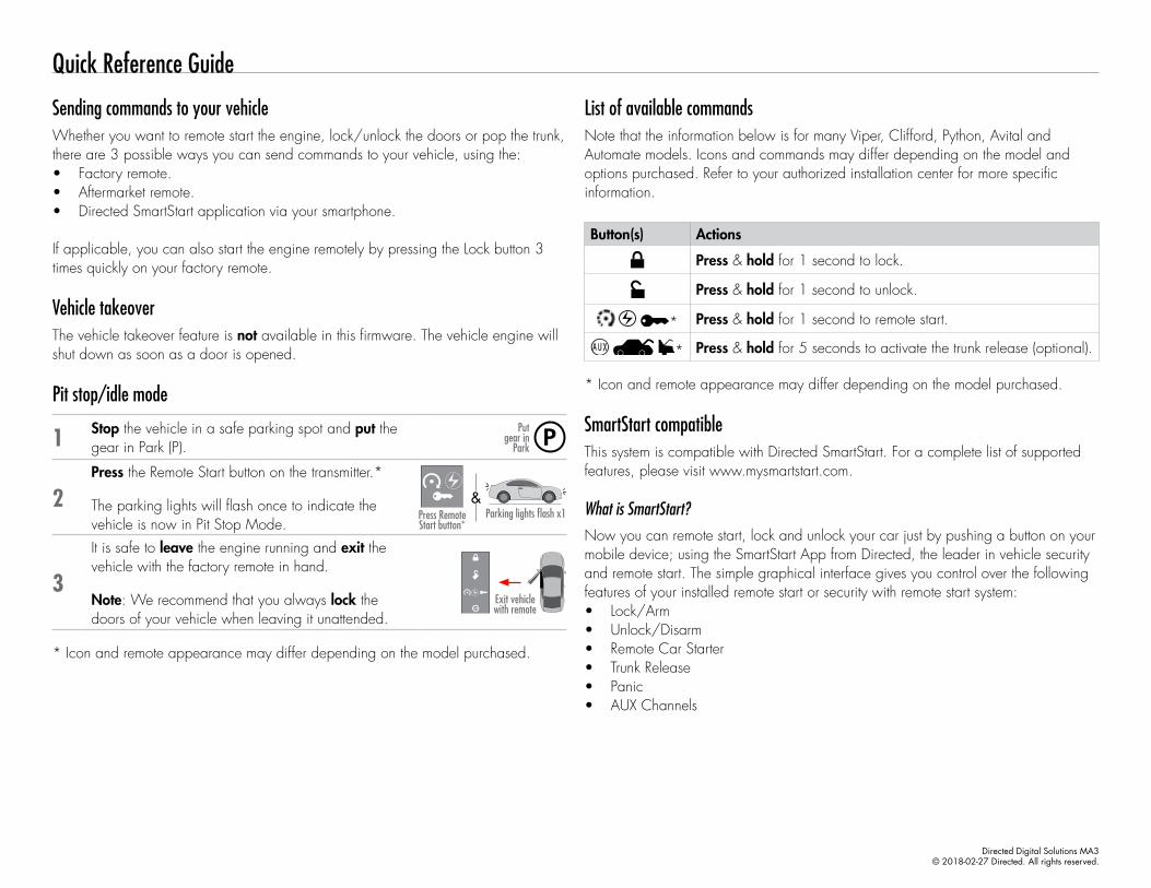
List of available commandsNote that the information below is for many Viper, Clifford, Python, Avital and Automate models. Icons and commands may differ depending on the model and options purchased. Refer to your authorized installation center for more specific information.
Button(s) Actions
Press & hold for 1 second to lock.
Press & hold for 1 second to unlock.
* Press & hold for 1 second to remote start.
* Press & hold for 5 seconds to activate the trunk release (optional).
* Icon and remote appearance may differ depending on the model purchased.
SmartStart compatibleThis system is compatible with Directed SmartStart. For a complete list of supported features, please visit www.mysmartstart.com.
What is SmartStart?Now you can remote start, lock and unlock your car just by pushing a button on your mobile device; using the SmartStart App from Directed, the leader in vehicle security and remote start. The simple graphical interface gives you control over the following features of your installed remote start or security with remote start system: • Lock/Arm• Unlock/Disarm• Remote Car Starter• Trunk Release• Panic• AUX Channels
Sending commands to your vehicleWhether you want to remote start the engine, lock/unlock the doors or pop the trunk, there are 3 possible ways you can send commands to your vehicle, using the:• Factory remote.• Aftermarket remote.• Directed SmartStart application via your smartphone.
If applicable, you can also start the engine remotely by pressing the Lock button 3 times quickly on your factory remote.
Vehicle takeoverThe vehicle takeover feature is not available in this firmware. The vehicle engine will shut down as soon as a door is opened.
Pit stop/idle mode
1 Stop the vehicle in a safe parking spot and put the gear in Park (P).
Put gear in
Park
2Press the Remote Start button on the transmitter.*
The parking lights will flash once to indicate the vehicle is now in Pit Stop Mode.
Parking lights flash x1
14:36
Press Remote Start button*
&
3
It is safe to leave the engine running and exit the vehicle with the factory remote in hand.
Note: We recommend that you always lock the doors of your vehicle when leaving it unattended.
14:36Exit vehicle with remote
* Icon and remote appearance may differ depending on the model purchased.
Directed Digital Solutions MA3© 2018-02-27 Directed. All rights reserved.

You can also control multiple vehicles – great for families – and assign more than one user to control a vehicle. It’s easy with SmartStart! But, this is only the beginning! SmartStart is loaded with additional features including GPS tracking, SmartSchedule, vehicle status, roadside assistance, parked car finder and more.
The application enables a “Cloud-Connected Car” like never before, providing 2-way interaction with your vehicle. Connectivity is managed through the Directed Cloud Services (DCS) network linking car, app, end user, and the Internet.
For more information, visit www.mysmartstart.com.
Notes
Directed Digital Solutions MA3© 2018-02-27 Directed. All rights reserved.