Embed Size (px)
Citation preview

Installation guide 854 ATG Page 1
Installation guide 854 Advanced Technology Gauge
June 2010
Part no. 4416.225
Revision 7
Enraf B.V.
P.O. Box 812
2600 AV Delft
Netherlands
Tel. : +31 15 2701 100
Fax : +31 15 2701 111
E-mail : [email protected]
Website : http://www.honeywellenraf.com

Preface
Page 2 Installation guide 854 ATG
Preface
The Honeywell Enraf 854 ATG is a servo gauge which measures the liquid level and can also be
programmed to measure two additional interface levels.
This installation guide is intended for technicians involved in the mechanical and electrical
installation of the Honeywell Enraf Series 854 ATG (Advanced Technology Gauge).
EC declaration of conformity
Refer to the EC declaration of conformity, shipped with the instrument.
Note: All connections to the instrument must be made with shielded cables with exception of the
mains, alarm outputs and Honeywell Enraf field bus cable. The shielding must be grounded in
the cable gland on both ends of the cable.
Legal aspects
The mechanical and electrical installation shall only be carried out by trained personnel with
knowledge of the requirements for installation of explosion-proof equipment in hazardous areas.
The information in this installation guide is the copyright property of Enraf B.V., Netherlands.
Enraf B.V. disclaims any responsibility for personal injury or damage to equipment caused by:
• Deviation from any of the prescribed procedures;
• Execution of activities that are not prescribed;
• Neglect of the general safety precautions for handling tools, use of electricity and
microwave radiation.
The contents, descriptions and specifications in this installation guide are subject to change
without notice. Enraf B.V. accepts no responsibility for any errors that may appear in this
installation guide.
Additional information
Do not hesitate to contact Honeywell Enraf or its representative if you require additional
information.

Safety
Installation guide 854 ATG Page 3
Safety
Safety aspects of 854 ATG
Warning
Do not use the instrument for anything else than its intended purpose.
For medium pressure versions (till 6 bar), the 854 ATG drum compartment housing is of
aluminium, and for chemical version it is of stainless steel.
For high pressure version (max. 40 bar; max. 25 bar in acc. to PED), the 854 ATG housing is of
stainless steel.
The housing of the 854 ATG is explosion-proof:
• II 1/2 G Ex d IIB T6 Ga/Gb or II 1/2G Ex de IIB T6 Ga/Gb or
II 1/2 G Ex d [ia Ga] IIB T6 Ga/Gb or II 1/2G Ex de [ia Ga] IIB T6 Ga/Gb;
acc. to KEMA 01ATEX2092 X, certified by KEMA, Netherlands
• Ex d [ia Ga] IIB T6 Ga/Gb or Ex de [ia Ga] IIB T6 Ga/Gb; acc. to IECEx KEM 10.0007X,
certified by KEMA, Netherlands
• Class I, Division 1, Groups B, C & D acc. to ANSI/NFPA no. 70, certified by Factory
Mutual Research USA (FM no.: 3Q2A9.AX)
Environmental conditions for the 854 ATG are:
ambient temperature : -40 to + 65 °C (-40 to +149 °F)
operating pressure : max. 6 bar for medium pressure and chemical version
max. 40 bar; max. 25 bar in acc. to PED for high pressure version
relative humidity : 0 - 100 %
ingress protection : IP65 (NEMA 4), suitable for outdoor installation
The drum compartment, which is in contact with the tank atmosphere, is separated from electronic
compartment. A magnetic coupling transfers the drum movement (hence, displacer movement) to
electronic compartment.
Wiring for intrinsically safe options, such as temperature or pressure measurement, is fed via two
separate cable entries.

Safety
Page 4 Installation guide 854 ATG
The 854 ATG covers can optionally be provided with sealing facilities on blocking devices, which
prevents unauthorized opening.
Warning
Improper installation of cable glands, conduits or stopping plugs
will invalidate the Ex approval of the 854 ATG.
Personal safety
The technician must have basic technical skills to be able to safely install the equipment.
When the 854 ATG is installed in a hazardous area, the technician must work in accordance with
the (local) requirements for electrical equipment in hazardous areas.
Warning
In hazardous areas it is compulsory to use personal protection and safety gear such as:
hard hat, fire-resistive overall, safety shoes, safety glasses and working gloves.
Avoid possible generation of static electricity.
Use non-sparking tools and explosion-proof testers.
Make sure no dangerous quantities of combustible gas mixtures
are present in the working area.
Never start working before the work permit has been signed by all parties.
Pay attention to the kind of product in the tank. If any danger for health,
wear a gas mask and take all necessary precautions.
Safety conventions
“Warnings”, “Cautions” and “Notes” are used throughout this installation guide to bring special
matters to the immediate attention of the reader.
• A Warning concerns danger to the safety of the technician or user;
• A Caution draws the attention to an action which may damage the equipment;
• A Note points out a statement deserving more emphasis than the general text, but not
requiring a “Warning” or a “Caution”.
General precautions
Installation guide 854 ATG Page 5
General precautions
Caution
During transport of the gauge the motor block
should be locked.
This is for protection of the weighing system.
Caution
The box in which the 854 arrives also contains
the measuring drum.
This is a precision measuring device and shall only
be installed by a qualified commissioning engineer.
Accurate measurement requires an undamaged
and clean drum.
Figure 1 Motor(un)locking
Special tools
Screw driver for Hex Allen-key screws M4 (length min. 22 mm) Part No.: 2998.506
Tommy bar Part No.: 2998.026

Mechanical installation
Page 6 Installation guide 854 ATG
Mechanical installation
Note: The entire installation procedure shall be in accordance with national, local and company
regulations.
Preparation for transportation of the gauge
Caution
Do not transport the instrument with the motor unlocked. Refer to figure 1 for motor locking.
Drum should be transported in original protective box. Drum and displacer shall only be installed
by a qualified commissioning engineer.
Process connection
The 854 ATG can be ordered with race face or flat face flange. Select gasket that is suitable for
flange type, maximum pressure and product to be stored. Mount instrument flange horizontally.
Warning
Verify that tank or drum compartment is depressurized before opening
the tank or drum compartment cover of 854 ATG.
The 854 ATG can be adapted to various process connection flanges via adapters/calibration
chambers as specified in Appendix B. Verify that maximum working pressure of adapter/calibration
chamber complies with pressure in your tank.
Note: When using 854 ATG on pressurized tank, it is recommended to install a suitable valve
between tank and 854 ATG to isolate the instrument from the process when required.
The valve shall have an opening large enough to feed through the displacer.
Mechanical installation
Installation guide 854 ATG Page 7
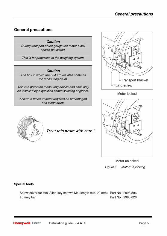
Orientation of 854 ATG gauge on tank
Mount the gauge in one of the following two ways.
Figure 2 Orientation of the gauge on a tank (top view)
On a stilling well or guide pole, the orientation of the gauge may be chosen freely.
Note: The weight of the 854 ATG for: - medium pressure version is : 16 kg (35 lbs);
- chemical version is : 21 kg (46 lbs);
- high pressure version is : 26 kg (57 lbs).

Mechanical installation
Page 8 Installation guide 854 ATG
Bolts
Secure the gauge adapter by using appropriate bolts. *)
Flange type
Number of bolts
Diameter x minimum length
NW50, ND6
4
M12 x 50
NW50, ND40
4
M16 x 60
2", 150 lbs
4
5/8" x 3" (M16 x 80)
2", 300 lbs
8
5/8" x 3" (M16 x 80)
6", 150 lbs
8
3/4" x 3
1/4" (M20 x 80)
6", 300 lbs
12
3/4" x 4" (M20 x 100)
*) Bolt dimensions (acc. to DIN 2527, ANSI B16.5) are given in the table.
Mounting a pressure gauge set
1 Connect T-piece horizontally to drum house.
2 Check whether manometer is suitable for the maximum pressure in the tank.
3 Mount manometer and vent valve (figure 3).
4 Close vent valve.
5 Gently open valve between tank and drum compartment and check for leakage on all
connections.
Figure 3 Mounting a pressure gauge set on a 854 Servo gauge

Mechanical installation
Installation guide 854 ATG Page 9
Grounding
Warning
For proper grounding of the 854 ATG, install a copper strip under one of
the flange bolts for each flange.
Place shark rings between flange and strip (figure 4).
Figure 4 Example of flange ground
Note:
Also in case of tanks with cathodic protection, the 854 ATG must be grounded to the tank.
Cathodic protection can be maintained by isolating the cable screen/armouring or conduit.

Electrical installation
Page 10 Installation guide 854 ATG
Electrical installation
The entire electrical installation shall be in accordance with International Standard IEC 79-14 for
electrical equipment to be installed in hazardous areas.
Warning
The instrument may not be opened when an explosion atmosphere may be present.
Failure to do so may cause danger to persons or damage the equipment.
Figure 5 Blocking / sealing facilities
Caution
Before opening the electronic and terminal compartment cover, remove the optional
blocking devices which locks the covers: “A”: for electronic compartment cover and
terminal compartment cover; “B”: for drum compartment cover.
Caution
Do not damage the thread of the covers and instrument and keep the thread free of dirt.
After opening, grease it lightly with anti seize grease.
When closing, never tighten the covers before the threads are properly engaged.
The covers should be turned counter-clockwise until the thread clicks in place,
then turn clockwise until the covers are fully closed.
After closing the covers, do not forget to place the blocking devices.

Electrical installation
Installation guide 854 ATG Page 11
Preparing gauge for electrical installation
Mains voltage selector
Check whether voltage selector is set correctly as
indicated on identification label of 854 ATG as well as
for the presented supply.
The voltage selector is located inside electronic
compartment (on the top of backplane).
It is marked with 'A' in figure 6.
The 854 ATG operates on a mains voltage of 110,
130, 220 Vac (+10% to -20%) and 230 Vac (±15%).
A special 65 Vac (+10% to -20%) is available.
Figure 6 Voltage selector
Power rating: 25 VA.
Frequency: 50 to 60 Hz (±10%). Imax
= 2 A.
Install an explosion-proof mains switch in the mains supply cable to each 854 ATG.
Specify which switch you need to operate the 854 ATG.
Note:
For 240 V supply voltage, set the voltage selector to 230 V.
Supply voltage may then vary from +10% to -20%.
To change voltage setting, proceed as follows:
1) Check the local mains voltage.
2) Open electronic compartment cover.
3) If necessary, change voltage selector to applicable voltage;
• Remove mains supply indication plate
• Slide switch in appropriate position (refer to figure 6.)
• Place mains supply indication plate and lock it
4) Close cover.
Caution
Changes of the mains setting shall be marked on the identification label of the 854 ATG.

Electrical installation
Page 12 Installation guide 854 ATG
External fusing
The 854 ATG is internally fused on secondary side of transformer (fuses are located on GPS
board). Therefore, external fuses must be installed in the mains supply cable to each 854 ATG.
mains voltage fuse value (in accordance with IEC 127-2-3)
220 Vac or 230 Vac 315 mA slow
110 Vac or 130 Vac 630 mA slow
65 Vac 1 A slow
Cable glands / conduit
Cable glands:
Explosion-proof (Ex-d) or increased safe (Ex-e) cable glands must be used, depending on local
requirements. Refer to the Ex-marking on the identification label of the 854 ATG to determine
which type of cable glands is required.
Note: Mount the glands according to the supplier’s instructions.
Conduit:
If the 854 ATG is installed in a hazardous area, threaded rigid metal conduit or threaded steel
intermediate metal conduit shall be used.
Note: If the 854 ATG is installed in a hazardous area, Ex d certified conduit seals must be applied
directly at the wall of the 854 ATG to seal the cabling in the conduit.
Depending on the wiring configuration, one to four ¾” NPT threaded cable glands (or rigid
conduits) may be required with the 854 ATG.
Note: Seal the unused cable inlets with an approved ¾” NPT threaded stopping plug.
Warning
Improper installation of cable glands, conduit or stopping plugs will invalidate
the Ex approval of your 854 ATG.

Electrical installation
Installation guide 854 ATG Page 13
Grounding
The 854 ATG housing should be properly grounded to the ground reference (generally the tank).
This is a safety grounding requirement. Grounding can be performed by copper strips across the
flanges (refer to section Grounding at mechanical installation), or by a ground wire.
With last mentioned method, use one of the external ground terminals of the 854 ATG.
Note: Grounding shall be performed in accordance with local regulations.
Caution
Safety depends on proper grounding. Check the resistance of the ground connection
directly after installation. The measured ground resistance shall be below the maximum
prescribed by local grounding requirements.
Warning
When measuring the ground resistance, use a suitable explosion-proof tester.
Lay-out terminal compartment
The terminal compartment on top of the 854 ATG is divided into a non-intrinsically safe and an
intrinsically safe part. Cable entries are ¾” NPT.
Figure 7 Location of 854 terminal compartment
The non-intrinsically safe cabling may only enter at the two right hand side cable entries (figure 7).
Warning
The Instrument may not be opened when an explosive atmosphere may be present.

Electrical installation
Page 14 Installation guide 854 ATG
Non-intrinsically safe cabling
Mains cabling : Must be suitable for the 854 ATG power rating and, moreover, approved for
the use in hazardous areas.
Honeywell
Enraf field bus : One twisted pair cable is recommended. Rmax
= 200 Ω / line; Cmax
= 1 µF.
Maximum length: 10 km.
Honeywell Enraf field bus lines may be interchanged. If local regulations
allow, mains and Honeywell Enraf field bus lines may share one cable.
Mind the isolation voltage of the cores in the cable; refer to the International
Standard IEC 61010-1.
Note: If a quad cable is used and all four cores are twisted together, use two
opposite cores for Honeywell Enraf field bus lines and the two others for
mains.
Relay output : Option. The relay output contacts are potential free.
Contact rating: Umax
= 50 Vac or 75 Vdc; Imax
= 3 A non-inductive
(CSA only: 0.6 A). Mind the isolation voltage of the cores in the cable; refer
to the International Standard IEC 61010-1.
Analog output : Option. Use shielded cable. External supply voltage: 12 to 64 Vdc.
See figure 9.
Terminal information:
Solid / stranded : 0.5…6 / 1.5…4
Flexible / stranded wire with end : 0.5…4 / 0.5…2.5
Tightening torque range (clamping) : 0.6…0.8 Nm (M 3)
Stripping length / Blade size : 8 / 0.6 x 3.5 mm
Figure 8 Non-Intrinsically safe connections

Electrical installation
Installation guide 854 ATG Page 15
When the voltage exceeds 30 Vdc,
an additional resistor is required.
The permitted operational areas are
shown in figure 9.
Operational area 1 represents the area of
operation without the need of an external loop
resistance.
Operational area 2 shows the area where
a resistance is required.
The power rating of the external resistor
depends on the value of the resistor.
We recommend 1 W / kΩ Figure 9 Selecting the external loop resistor
Optional RS communication connections
For the cable connections of the mains and the alarm contacts, refer to previous section.
Caution
Keep the RS-232C / RS-485 lines as short as possible.
RS-232C : Cable requirements: maximum length 15 metres (50 ft); twisted and shielded.
RS-485 : Cable requirements: maximum length 1200 metres (3900 ft); twisted and shielded.
Figure 10 RS-232C / RS-485 connections

Electrical installation
Page 16 Installation guide 854 ATG
Intrinsically safe options
The cables for the intrinsically safe options shall only be fed through the cable entries at the side of
the intrinsically safe (blue) terminals. Blue marked cables are recommended for the intrinsically
safe options.
Caution
The intrinsically safe options described in this section are explosion-proof certified.
Make sure that the certificate of approval is available on site and act in accordance
with the instructions as given in the approval certificate.
Caution
Intrinsically safe wiring shall be separated from all other wiring.
Cable lay-outs shall be in accordance with local regulations.
Note:
The shield of the intrinsically safe cable shall not be connected inside the 854 ATG housing.
Connect the shield of the cable externally in the cable gland at both ends of the cable.
Device Cable requirements
Spot temperature element : Shielded; Rmax
= 12 Ω / line.
Average temp. element : Twisted pair and shielded; Rmax
= 25 Ω / line.
(combined water probe) Wiring between the 854 ATG and 762 VITO must be protected with
EMC shielded conduit. Same conditions for connection to 862 MIR.
Pressure transmitters : Twisted pair and shielded; Rmax
= 25 Ω / line (only pressure
transmitters with HART® protocol).
Pressure transmitter P1 is the bottom transmitter (measures liquid
head) and P3 is the top transmitter (measures vapour pressure).
Note: If pressure transmitters are connected to HART input 2, it must be verified that the maximum
values for current and power of the HCU option board HART input 2 circuit are not exceeding
the maximum values of the connected pressure transmitters. Refer to Appendix C.
If the values of the HART input 2 circuit are too high, then connect the pressure transmitters to
HART input 1 and the 762 VITO Interface to HART input 2 (only possible when HART input 1 is
available!).
Electrical installation
Installation guide 854 ATG Page 17
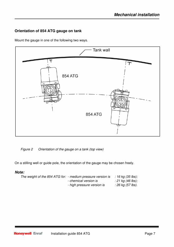
Device Cable requirements
977 Tank Side Indicator : Twisted pair and shielded; Rmax
= 5 Ω / line, maximum cable length
50 m (160 ft).
GFC (Foundation™ Fieldbus) : Requires external supply 9 – 24 Vdc
Nominal current 11 mA
Maximum current (startup) 16.70 mA
Water bottom probe : Twisted pair and shielded; Rmax
= 25 Ω / line.
(no VITO water sensor) (only with HART® protocol).
Note: If also pressure transmitters are connected, use a junction box for parallel connection of the
pressure transmitters and water bottom probe.
Figure 11 Intrinsically safe option connections

Appendix
Page 18 Installation guide 854 ATG
Appendix A
Dimensions 854 ATG (medium pressure and chemical version)

Appendix
Installation guide 854 ATG Page 19
Dimensions 854 ATG (high pressure version)

Appendix
Page 20 Installation guide 854 ATG
Appendix B
Available adapters & calibration chambers

Appendix
Installation guide 854 ATG Page 21
Appendix C
ATEX approval
The terminal compartment of the 854 ATG level gauge has been ATEX approved as explosion-
proof and as being increased safe. The type of cable glands that must used:
For protection type increased safe Ex e approved glands are to be used.
For protection type explosion proof Ex d approved glands or conduit are to be used.
Connection requirements of optional boards
The identification label on the 854 ATG indicates whether your instrument is equipped with an
optional board with intrinsically safe measuring circuits.
XPU-2 board (i.s. option), [Ex ia] IIB
Output circuit for 977 TSI:
Max. values : U = 21 V, I = 395 mA, P = 1.41 W
Max. permissible ext. inductance : 0.8 mH
Max. permissible ext. capacitance : 1.27 µF
HCU option board, [Ex ia] IIB
Spot temperature input circuit:
Max. values : U = 23.1 V, I = 221 mA, P = 0.19 W
Max. permissible ext. inductance : 3.5 mH
Max. permissible ext. capacitance : 980 nF
HART input 1 circuit (for 762 VITO Interface):
Max. values : U = 23.1 V, I = 90 mA, P = 0.52 W
Max. permissible ext. inductance : 15 mH
Max. permissible ext. capacitance : 1.02 µF
HART input 2 circuit (for HART® pressure transmitters and/or external water probe):
Max. values : U = 23.1 V, I = 148 mA, P = 0.86 W
Max. permissible ext. inductance : 7 mH
Max. permissible ext. capacitance : 1.02 µF
GFC option board, [Ex ia] IIC
Fieldbus interface circuit
Max. values : U = 24V, I = 380 mA, P = 5.32W
Effective internal inductance : 6.5 µH
Effective internal capacitance : 1.8 nF

Appendix
Page 22 Installation guide 854 ATG
Appendix D
Related documents
Instruction manual 854 ATG level gauge
Instruction manual 854 density option
Instruction manual SPU II Hard alarm output contacts
Installation guide 762 VITO Interface & 764, 765 or 766 VITO temperature and/or water sensor
Installation guide 977 Tank Side Indicator
Instruction manual XPU-2 option RS-232C/RS-485
Instruction manual Temperature, Water bottom and Analog output options
Instruction manual HIMS / HTG and vapour pressure (P3) measurement
Instruction manual Foundation™ Fieldbus Interface
Instruction manual 847 PET
Installation info 003 "Installation of Pressure Transmitters for HTG and HIMS

Notes
Installation guide 854 ATG Page 23

Page 24 Installation guide 854 ATG
Delftechpark 39 2628 XJ Delft Tel. :+31 15 2701 100 E-mail : [email protected] Webiste: www.honeywellenraf.com PO Box 812 2600 AV Delft The Netherlands We at Honeywell Enraf are committed to excellence. Information in this publication is subject to change without notice Enraf is a registered trade mark. Enraf B.V. Netherlands