Embed Size (px)
Citation preview
MCCMarine Commercial Control
D5A, D7A
Installation
1(1)
E

General Information .................................................. 4About the Installation Manual ................................. 4Installation ............................................................. 4Joint liability ........................................................... 5Certified engines .................................................... 5
Safety Information ................................................... 6Introduction ............................................................ 6Installation ............................................................. 6Safety directions for maintenance and service ....... 6Work Procedures ................................................... 6Important! .............................................................. 6
Presentation ............................................................. 8MCC ...................................................................... 8MCU ...................................................................... 8SDU ....................................................................... 9
Marine Commercial Control .................................... 10MCC system overview ......................................... 11MCU Panel layout ................................................ 12Menus .................................................................. 15Operation ............................................................. 17MCU menu flow chart ........................................... 18Setpoints ............................................................. 20
Shutdown system overview.................................... 21SDU indications ................................................... 22
Installation notes .................................................... 23Connection to engine ........................................... 23Interface information ............................................ 24Wiring terminals ................................................... 24
General arrangement drawing D5/D7 MCC ............. 27
Technical data MCU............................................... 28
Contents
4
General information
About the Installation ManualThis publication is intended as a guide for the installa-tion of the MCC (Marine Commercial Control). The pu-blication is not comprehensive and does not coverevery possible installation, but is to be regarded as re-commendations and guidelines applying to Volvo Pen-ta standards.
IMPORTANT! Installation of electrical systemsshall only be carried out by a professional marineelectrician.
IMPORTANT! Before attempting to install theMCU to its power supply or other externaldevices, always refer to General ArrangementDrawing for detailed information concerning in-stallation. When in doubt, contact Volvo Penta.
The recommendations in this manual are the result ofmany years practical experience of installations allover the world. Departures from recommended proce-dures etc. can however be necessary or desirable, inwhich case the Volvo Penta organisation will be gladto offer assistance in finding a solution for your parti-cular installation.
Installation manual for skilled professionalsThis Installation Manual has been published for pro-fessionals and qualified personnel. It is therefore as-sumed that persons using this book have sufficientknowledge of marine drive and monitoring systemsand are able to carry out related mechanical and elec-trical work.
It is the sole responsibility of the installer to ensurethat the installation work is carried out in a satisfacto-ry manner, that it is operationally in good order, thatthe approved materials and accessories are used andthat the installation meets all applicable rules and re-gulations.
Only parts delivered or approved by Volvo PentaOnly components, cables, connections etc, deliveredor approved by the manufacturer may be used. Themanufacturer will take no responsibility what so ever ifthis requirement is violated.
Updates in Service BulletinsVolvo Penta continuously upgrades its products andreserves the right to make changes. All the informa-tion contained in this manual is based on product dataavailable at the time of going to print. Notification ofany important modifications to the product causingchanges to installation methods after this date will bemade in Service Bulletins.
InstallationGreat care must be taken in the installation of enginesand their components. Always make absolutely surethat the correct specifications, drawings and any otherdata are available before starting work.
Plan installations with careThe installation must be planned very thoroughly anddone with the greatest care. Plan the installation sothat it is easy to carry out routine service operationsinvolving the replacement of components (comparethe Service Manual with the original drawings showingthe dimensions).
IMPORTANT! Maximum permissible length ofcable from engine to panel, is 40 m [130 ft].
The connection cable between the engine and the in-strument panel must be securely clamped. Rememberthat the connectors must also be supported so thatthey are not subjected to any tension. Cables mustnot be run too close to hot components on the engineor close to any other source of heat. Make sure that itis protected from mechanical wear, sharp edges andwater splashes. If necessary, run the cable throughprotective conduits.
IMPORTANT! Cables must also be run on a safedistance from equipment that may disturbcommunication signals, i.e. radio transmitters orhigh current equipment.
Avoid making joints in the system as far as possible.Cables and any joints must be accessible for inspec-tion and service
NOTE! The connectors must be installed “dry”, theymust not be packed with Vaseline etc.
General Information
5
General information
Certified enginesThe manufacturer of engines certified for national and local environmental legislation pledges that this legislationis met by both new and currently operational engines. The product must compare with the example approved forcertification purposes. So that Volvo Penta, as a manufacturer, can pledge that currently operational enginesmeet environmental regulations, the following must be observed during installation:
• Service of fuel pumps, pump settings and injectors must always be carried out by an authorised Volvo Pentaworkshop.
• The engine must not be modified in any way except with accessories and service kits developed for it byVolvo Penta.
• Installation of exhaust pipes and air intake ducts for the engine compartment must be carefully planned as itsdesign may affect exhaust emissions.
• Seals may only be broken by authorised personnel.
IMPORTANT! Use only Volvo Penta Genuine Parts. Otherwise AB Volvo Penta will no longer takeresponsibility for the engine meeting the certified design. All damage and costs caused by the use ofnon-genuine replacement parts will not be covered by Volvo Penta.
Joint liabilityEach engine consists of many components working together. One component deviating from its technical specifi-cation can cause a dramatic increase in the environmental impact of an engine. It is therefore vital that systemsthat can be adjusted are adjusted properly and that Volvo Penta Genuine Parts as used.
Certain systems (components in the fuel system for example) may require special expertise and special testingequipment. Some components are sealed at the factory for environmental reasons. No work should be carried outon sealed components except by authorised personnel.
EnvironmentRemember that most chemical products damage the environment if used incorrectly. Volvo Penta recommendsthe use of biodegradable degreasing agents for cleaning engine components, unless otherwise indicated. Takespecial care when working on board boats to ensure that oil and waste are taken for destruction and not acciden-tally pumped into the environment with bilgewater.
6
Safety information
Safety directions for maintenance and service WARNING! Installation, maintenance and service must be carried out with the engine stationary unless
stated otherwise in the instructions. Prevent inadvertent start of the engine by turning off the power with themain switch, locking it in the off position. Disconnect primary and secondary power supply (positive(+) andnegative(–) leads) and disable auxiliary starters. Place warning signs stating that work is in progress in everyposition from which the engine can be started.
Below is a summary of the risks you must observe and the safety precautions you must carry out when installingand configuring the Control System.
Before carrying out electric arc welding, thesemeasures of precaution should be at taken.
Safety Information
IntroductionRead this Installation Manual carefully before installa-tion. Improper installation may result in personal injuryor damage to property or the engine itself.
If you do not understand or are uncertain about anyoperation or information in this Installation Manual,please contact Volvo Penta organisation.
InstallationThis Installation Manual is produced for professionaluse only and must be used in conjunction with the rel-evant Operator’s Manual.
Volvo Penta will not assume any liability whatsoeverfor damage to materials or personal injury, which mayresult if the installation instructions are not followed orif the work is carried out by non-professional person-nel.
The installer is responsible for ensuring that the sys-tem operates in accordance with this Installation Man-ual.
Work ProceduresRefer to the specific Operator’s Manual for relevant in-formation where necessary, especially regarding safe-ty and engine operation.
The work must be performed at Volvo Penta’s serviceworkshops, boat builders or other authorized and suit-ably equipped workshops with personnel who have ap-propriate qualifications and experience.
Important!The following special warning symbols are found inthis manual and on the engine.
WARNING! Possible danger of personal injury,damage to property or mechanical malfunction ifthe instructions are not followed.
IMPORTANT! Used to draw your attention tosomething that can cause damage to ormalfunction of a product or damage to property.
NOTE! Used to draw your attention to important infor-mation that will facilitate the work or operation in pro-gress.
1. Disconnect primary and secondary power supply(positive(+) and negative(–) leads).
2. Disconnect fuses in the electrical connection boxon the engine.
7
Safety information
Take care to avoid all moving parts of the engineduring testing and operation. Approaching anengine which is operating is a hazard to personalsafety. Loose clothing or long hair can becomeentangled in moving parts, and may causeserious personal injury.
Never carry out work on an engine that issuspended from a hoist.
Only start the engine in a well-ventilated area. Ifoperating the engine in a closed area ensure thatthere is exhaust ventilation leading out of thework area to remove exhaust gases andcrankcase ventilation emissions.
The engine must not be run in areas where thereare explosive materials or gases.
Never allow an open flame or electric sparksnear the batteries. Never smoke in proximity tothe batteries. The batteries give off hydrogen gasduring charging, which when mixed with air canform an explosive mixture. This gas is easilyignited and highly flammable. Incorrectconnection of the battery can cause a singlespark, which is sufficient to cause a gas explo-sion. Do not alter the battery connections whenattempting to start the engine (spark risk) and donot lean over any of the batteries. Refer toinstructions in the Engine Instruction Manual.
Always ensure that the + (positive) and –(negative) battery leads are correctly installed ontheir corresponding terminal posts on thebatteries. Incorrect installation can result inserious damage to the electrical equipment.Refer to the wiring diagrams in the EngineInstruction Manual.
Always use protective eyewear when charging orhandling the engine batteries. The batteryelectrolyte fluid contains sulphuric acid which ishighly corrosive. If the battery electrolyte fluidcomes into contact with unprotected skin, washoff immediately using copious amounts of cleanwater and soap, then seek medical assistance. Ifthe electrolyte fluid comes in contact with theeyes, flush the eyes immediately (preferableusing an eye bath) with copious amounts ofclean water, and obtain medical assistancewithout delay.
IMPORTANT! AB Volvo Penta has developedand tested the complete system and itscomponents. Non-original Volvo Pentacomponents or components installed in a waythat differ from the instructions may causemalfunction of the system.
IMPORTANT! Use only Genuine Volvo PentaSpare Parts.
Use of non-original AB Volvo Penta spare partswill result in AB Volvo Penta being unable toassume liability for the engine meeting enginecertification requirements. Any type of damageresulting from the use of non-original VolvoPenta replacement parts for the roduct will not becovered under any warranty provided by ABVolvo Penta.
8
Presentation
Presentation
MCCThe Volvo Penta Marine Commercial Control (MCC) is a control & monitoring system for marine applications. TheMarine control unit (MCU) together with the Shutdown unit (SDU), provides completely redundant engine control.
MCUThe MCU controls and monitors the engine in 3 different applications – Emergency, auxiliary and combined.
Equipped with a graphic display with icons, symbols and bar-graphs for intuitive operation, together with high func-tionality this sets new standards in engine controls.
Functions
● On screen alarm list indication
● Event and time driven engine history for backtracing
● Running hours meter, number of starts counter
● Configurable 14 binary inputs and 14 binaryoutputs and 8 analog inputs
● Magnetic pick-up speed measurement (+redun-dant channel)
● Extension units for more I/O and Remote Displaypanel
● Password protection
● 3 operational modes – emergency, auxiliary, andcombined.
● 5 languages selectable on MCU
Communication● RS232 / Modbus RTU
● J1939, J1708/J1587
9
Presentation
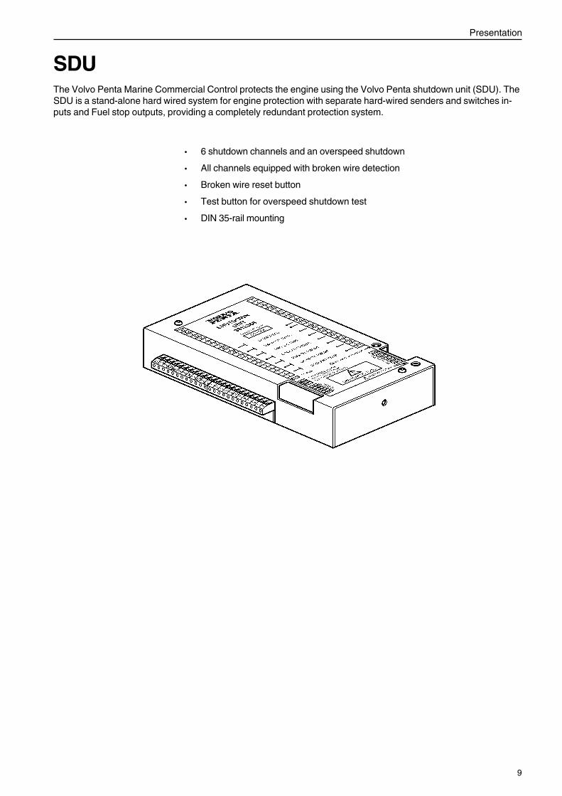
SDUThe Volvo Penta Marine Commercial Control protects the engine using the Volvo Penta shutdown unit (SDU). TheSDU is a stand-alone hard wired system for engine protection with separate hard-wired senders and switches in-puts and Fuel stop outputs, providing a completely redundant protection system.
● 6 shutdown channels and an overspeed shutdown
● All channels equipped with broken wire detection
● Broken wire reset button
● Test button for overspeed shutdown test
● DIN 35-rail mounting
10
Control System
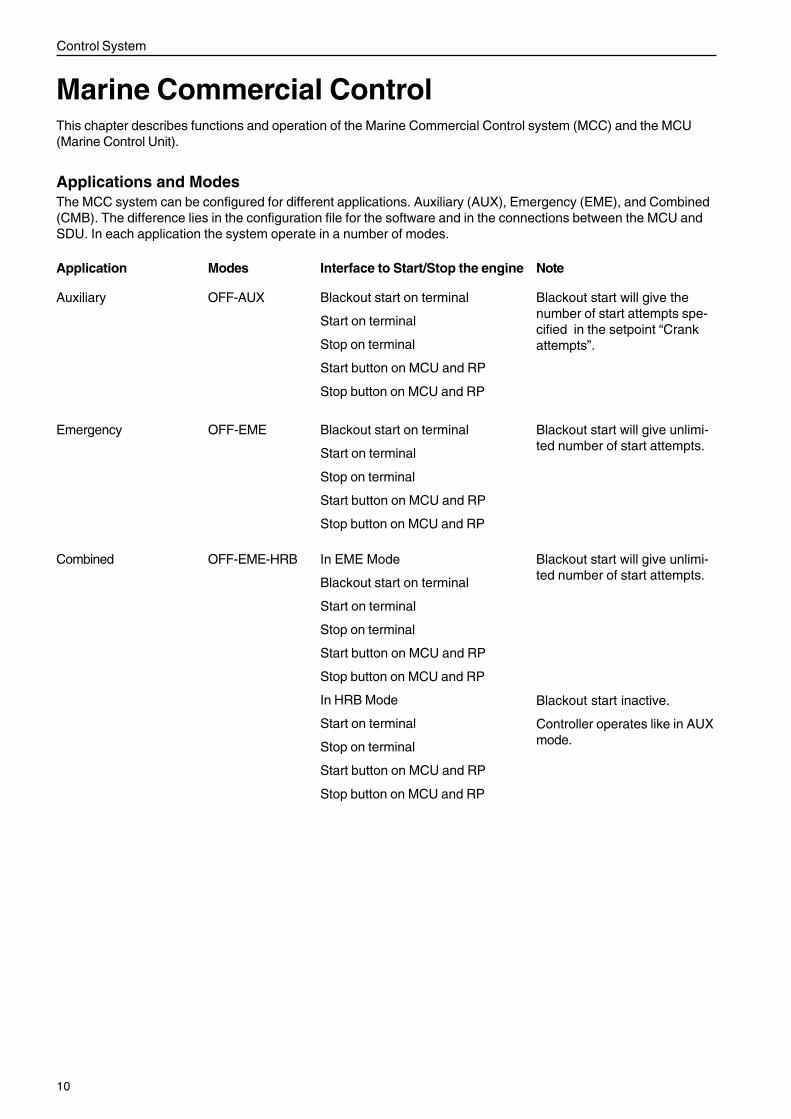
Marine Commercial ControlThis chapter describes functions and operation of the Marine Commercial Control system (MCC) and the MCU(Marine Control Unit).
Applications and ModesThe MCC system can be configured for different applications. Auxiliary (AUX), Emergency (EME), and Combined(CMB). The difference lies in the configuration file for the software and in the connections between the MCU andSDU. In each application the system operate in a number of modes.
Auxiliary OFF-AUX
Emergency OFF-EME
Combined OFF-EME-HRB
Application Modes Note
Blackout start will give thenumber of start attempts spe-cified in the setpoint “Crankattempts”.
Blackout start will give unlimi-ted number of start attempts.
Blackout start will give unlimi-ted number of start attempts.
Blackout start on terminal
Start on terminal
Stop on terminal
Start button on MCU and RP
Stop button on MCU and RP
Blackout start on terminal
Start on terminal
Stop on terminal
Start button on MCU and RP
Stop button on MCU and RP
In EME Mode
Blackout start on terminal
Start on terminal
Stop on terminal
Start button on MCU and RP
Stop button on MCU and RP
In HRB Mode
Start on terminal
Stop on terminal
Start button on MCU and RP
Stop button on MCU and RP
Interface to Start/Stop the engine
Blackout start inactive.
Controller operates like in AUXmode.
11
Control System
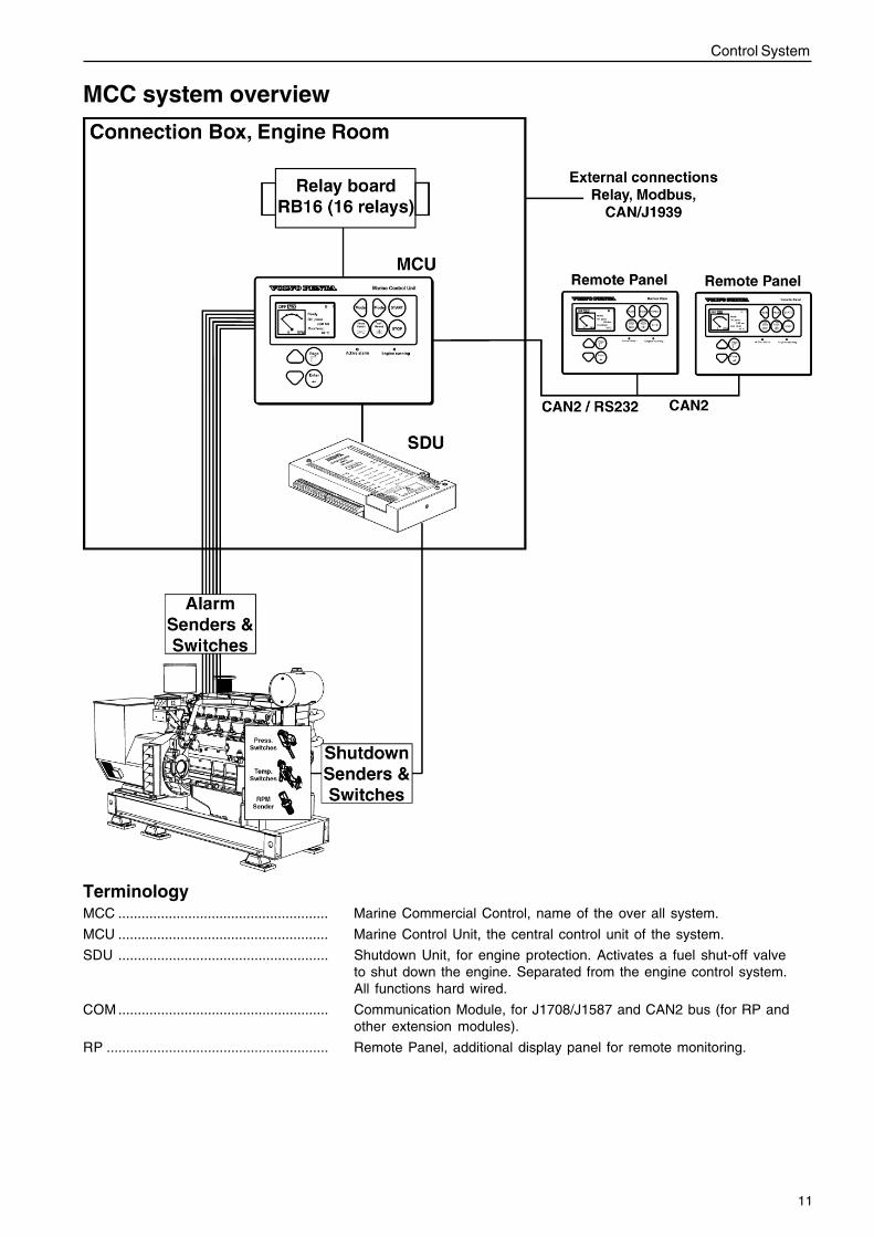
MCC system overview
TerminologyMCC ...................................................... Marine Commercial Control, name of the over all system.
MCU ...................................................... Marine Control Unit, the central control unit of the system.
SDU ...................................................... Shutdown Unit, for engine protection. Activates a fuel shut-off valveto shut down the engine. Separated from the engine control system.All functions hard wired.
COM ...................................................... Communication Module, for J1708/J1587 and CAN2 bus (for RP andother extension modules).
RP ......................................................... Remote Panel, additional display panel for remote monitoring.
12
Control System
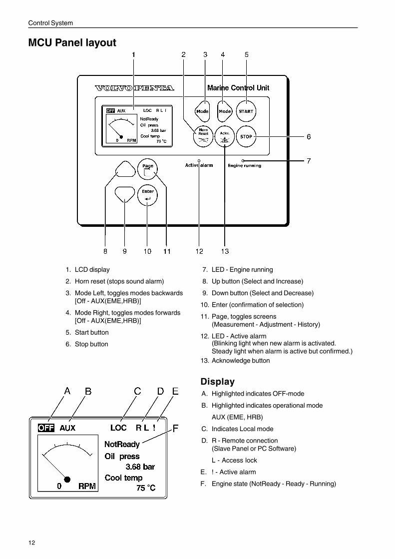
1. LCD display
2. Horn reset (stops sound alarm)
3. Mode Left, toggles modes backwards[Off - AUX(EME,HRB)]
4. Mode Right, toggles modes forwards[Off - AUX(EME,HRB)]
5. Start button
6. Stop button
7. LED - Engine running
8. Up button (Select and Increase)
9. Down button (Select and Decrease)
10. Enter (confirmation of selection)
11. Page, toggles screens(Measurement - Adjustment - History)
12. LED - Active alarm
MCU Panel layout
(Blinking light when new alarm is activated.Steady light when alarm is active but confirmed.)
13. Acknowledge button
DisplayA. Highlighted indicates OFF-mode
B. Highlighted indicates operational mode
AUX (EME, HRB)
C. Indicates Local mode
D. R - Remote connection(Slave Panel or PC Software)
L - Access lock
E. ! - Active alarm
F. Engine state (NotReady - Ready - Running)
13
Control System
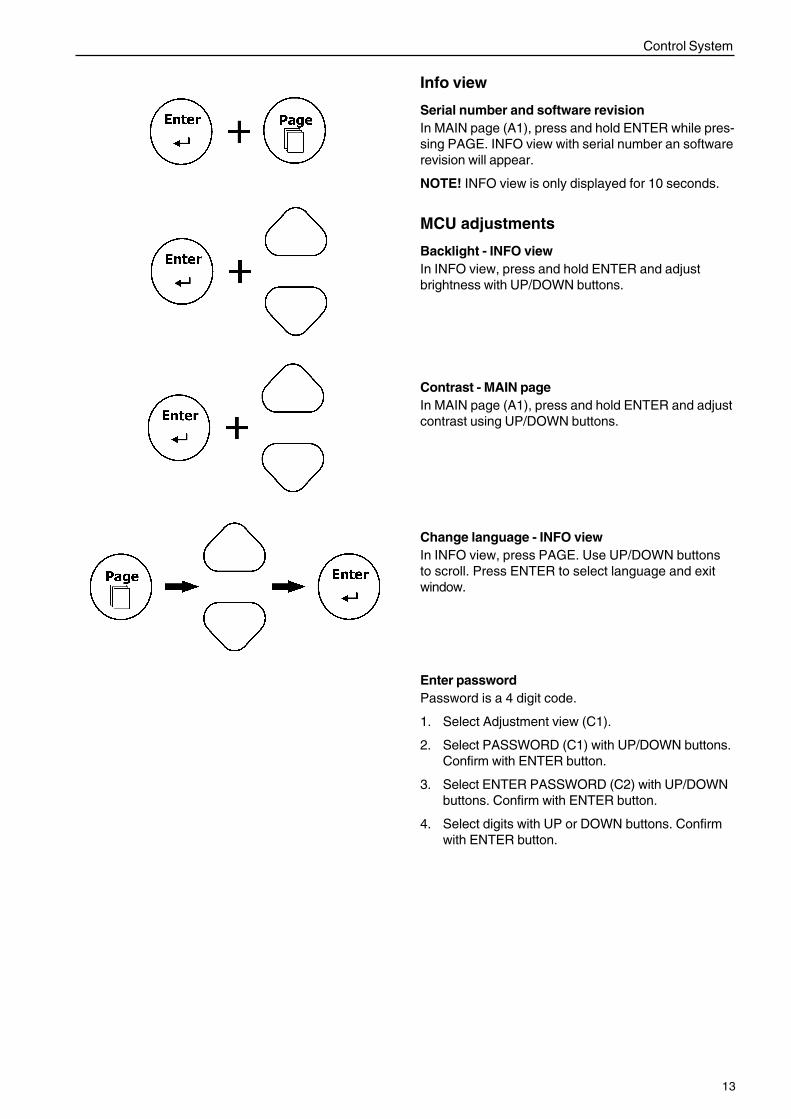
Info view
Serial number and software revisionIn MAIN page (A1), press and hold ENTER while pres-sing PAGE. INFO view with serial number an softwarerevision will appear.
NOTE! INFO view is only displayed for 10 seconds.
MCU adjustments
Backlight - INFO viewIn INFO view, press and hold ENTER and adjustbrightness with UP/DOWN buttons.
Change language - INFO viewIn INFO view, press PAGE. Use UP/DOWN buttonsto scroll. Press ENTER to select language and exitwindow.
Contrast - MAIN pageIn MAIN page (A1), press and hold ENTER and adjustcontrast using UP/DOWN buttons.
Enter passwordPassword is a 4 digit code.
1. Select Adjustment view (C1).
2. Select PASSWORD (C1) with UP/DOWN buttons.Confirm with ENTER button.
3. Select ENTER PASSWORD (C2) with UP/DOWNbuttons. Confirm with ENTER button.
4. Select digits with UP or DOWN buttons. Confirmwith ENTER button.
14
Control System
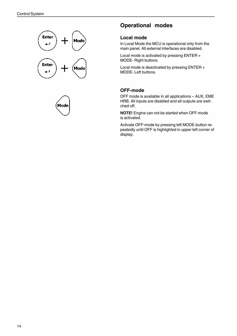
Operational modes
Local modeIn Local Mode the MCU is operational only from themain panel. All external interfaces are disabled.
Local mode is activated by pressing ENTER +MODE- Right buttons.
Local mode is deactivated by pressing ENTER +MODE- Left buttons.
OFF-modeOFF mode is available in all applications – AUX, EMEHRB. All inputs are disabled and all outputs are swit-ched off.
NOTE! Engine can not be started when OFF-modeis activated.
Activate OFF-mode by pressing left MODE-button re-peatedly until OFF is highlighted in upper left corner ofdisplay.
15
Control System
1
3
2
A
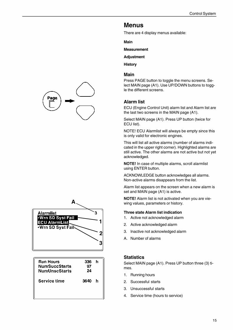
MenusThere are 4 display menus available:
Main
Measurement
Adjustment
History
MainPress PAGE button to toggle the menu screens. Se-lect MAIN page (A1). Use UP/DOWN buttons to togg-le the different screens.
Alarm listECU (Engine Control Unit) alarm list and Alarm list arethe last two screens in the MAIN page (A1).
Select MAIN page (A1). Press UP button (twice forECU list).
NOTE! ECU Alarmlist will always be empty since thisis only valid for electronic engines.
This will list all active alarms (number of alarms indi-cated in the upper right corner). Highlighted alarms arestill active. The other alarms are not active but not yetacknowledged.
NOTE! In case of multiple alarms, scroll alarmlistusing ENTER button.
ACKNOWLEDGE button acknowledges all alarms.Non-active alarms disappears from the list.
Alarm list appears on the screen when a new alarm isset and MAIN page (A1) is active.
NOTE! Alarm list is not activated when you are vie-wing values, parameters or history.
Three state Alarm list indication1. Active not acknowledged alarm
2. Active acknowledged alarm
3. Inactive not acknowledged alarm
A. Number of alarms
StatisticsSelect MAIN page (A1). Press UP button three (3) ti-mes.
1. Running hours
2. Successful starts
3. Unsuccessful starts
4. Service time (hours to service)
16
Control System
Statistic values can be adjusted from PC software(password protected), contact your Volvo Penta dea-ler.
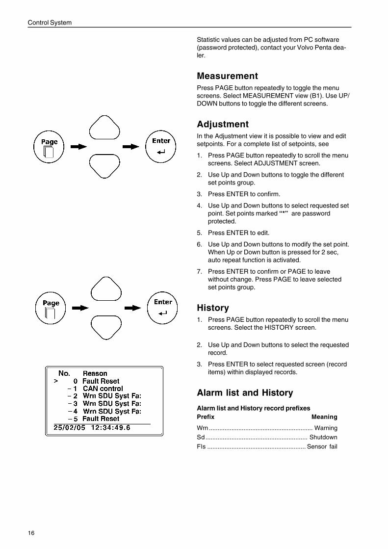
MeasurementPress PAGE button repeatedly to toggle the menuscreens. Select MEASUREMENT view (B1). Use UP/DOWN buttons to toggle the different screens.
AdjustmentIn the Adjustment view it is possible to view and editsetpoints. For a complete list of setpoints, see
1. Press PAGE button repeatedly to scroll the menuscreens. Select ADJUSTMENT screen.
2. Use Up and Down buttons to toggle the differentset points group.
3. Press ENTER to confirm.
4. Use Up and Down buttons to select requested setpoint. Set points marked “*” are passwordprotected.
5. Press ENTER to edit.
6. Use Up and Down buttons to modify the set point.When Up or Down button is pressed for 2 sec,auto repeat function is activated.
7. Press ENTER to confirm or PAGE to leavewithout change. Press PAGE to leave selectedset points group.
History1. Press PAGE button repeatedly to scroll the menu
screens. Select the HISTORY screen.
2. Use Up and Down buttons to select the requestedrecord.
3. Press ENTER to select requested screen (recorditems) within displayed records.
Alarm list and History
Alarm list and History record prefixesPrefix Meaning
Wrn ............................................................ Warning
Sd........................................................... Shutdown
Fls ......................................................... Sensor fail
17
Control System
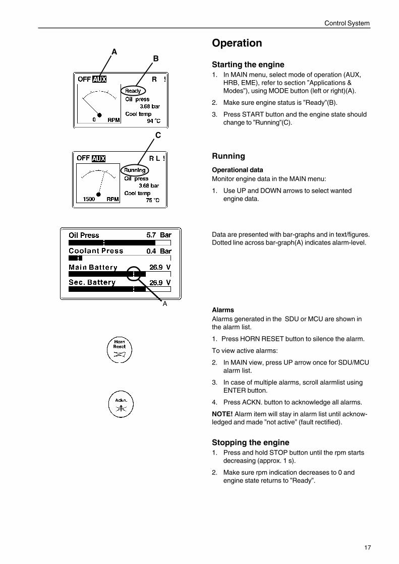
Operation
Starting the engine1. In MAIN menu, select mode of operation (AUX,
HRB, EME), refer to section ”Applications &Modes”), using MODE button (left or right)(A).
2. Make sure engine status is ”Ready”(B).
3. Press START button and the engine state shouldchange to ”Running”(C).
Running
Operational dataMonitor engine data in the MAIN menu:
1. Use UP and DOWN arrows to select wantedengine data.
AB
C
Data are presented with bar-graphs and in text/figures.Dotted line across bar-graph(A) indicates alarm-level.
AAlarmsAlarms generated in the SDU or MCU are shown inthe alarm list.
1. Press HORN RESET button to silence the alarm.
To view active alarms:
2. In MAIN view, press UP arrow once for SDU/MCUalarm list.
3. In case of multiple alarms, scroll alarmlist usingENTER button.
4. Press ACKN. button to acknowledge all alarms.
NOTE! Alarm item will stay in alarm list until acknow-ledged and made ”not active” (fault rectified).
Stopping the engine1. Press and hold STOP button until the rpm starts
decreasing (approx. 1 s).
2. Make sure rpm indication decreases to 0 andengine state returns to ”Ready”.
18
Control System
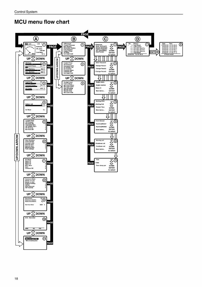
MCU menu flow chart
19
Control System
Main page (A)
A1.The main page of the system. Most important para-meters are shown. Mode change is possible.
A2 & A3.Displays analogue parameters measured by the MCU.
A4.System voltage information measured by the MCU.
A5 & A6.Status of MCU 14 digital inputs.0 - input inactive1 - input active.Inverted 0 or 1 indicates alarm due to current status.
NOTE! Pages can be used to verify interface to supe-rior system. Activate signal from superior system andmonitor input state change.
A7. & A8.Pages display status of MCU 14 digital outputs.0 - input inactive1 - input active.
A9.Statistic information. Run hours of the engine, No. ofsuccessful start, etc.
A10.Will always be empty.
A11.Displays alarms from the Shutdown system (SDU)and MCU. Navigate alarmlist with Enter button.
NOTE! Engine cannot be started with active or unack-nowledged SD.
Measurement (B)
B1. - B3.MCU to external interface. Modbus.
Adjustments (C)
C1.Menu for change of setpoints. Navigate with up anddown arrows - select with Enter.
C2.Enter and change passwords. Most setpoints arepassword protected to avoid accidental changing.Password 0 in standard configuration.
C3.Page for changing basic settings of the systems, e.ggovernor mode and speed select.
C4.Page for changing Engine parameters settings. Referto section ”MCU adjustments” for details.
C5.Page for changing parameters concerning MCU engi-ne protection functionality.
NOTE! In the MCC system engine protection functio-nality is handled by the SDU. Changing these set-points will not affect the SDU.
C6.Changing setpoints concerning MCU telematics func-tionality.
NOTE! Telematics functionality is not supported byVolvo Penta. Refer to http://www.huegli-tech.com
C7.Page or changing date and time.
History (D)
D1.Displays previous actions/alarms. Enter button forfurther information, D2 (D3, D4, etc).
20
Control System
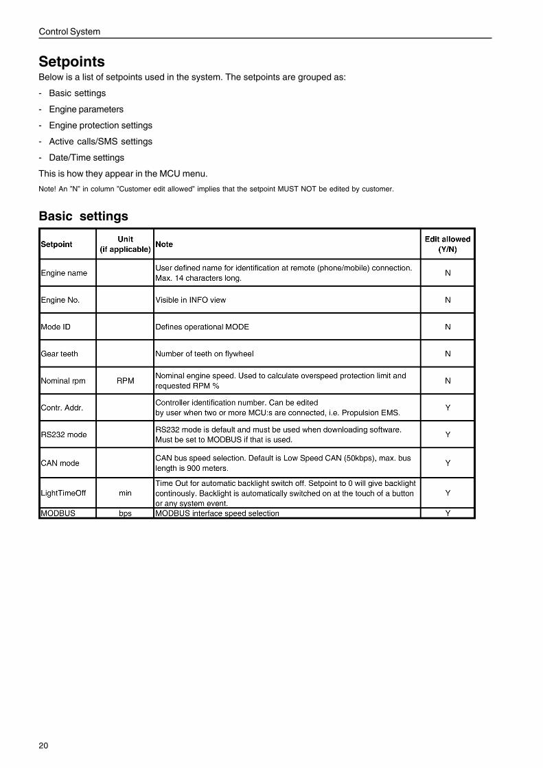
SetpointsBelow is a list of setpoints used in the system. The setpoints are grouped as:
- Basic settings
- Engine parameters
- Engine protection settings
- Active calls/SMS settings
- Date/Time settings
This is how they appear in the MCU menu.
Note! An ”N” in column ”Customer edit allowed” implies that the setpoint MUST NOT be edited by customer.
Basic settings
21
SDU
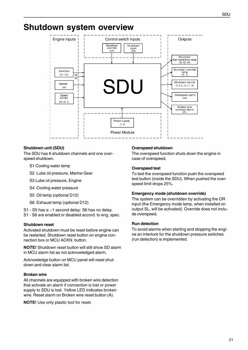
Shutdown unit (SDU)The SDU has 6 shutdown channels and one over-speed shutdown.
S1 Cooling water temp
S2 Lube oil pressure, Marine Gear
S3 Lube oil pressure, Engine
S4 Cooling water pressure
S5 Oil temp (optional D12)
S6 Exhaust temp (optional D12)
S1 - S5 has a ~1 second delay: S6 has no delay.S1 - S6 are enabled or disabled accord. to eng. spec.
Shutdown resetActivated shutdown must be reset before engine canbe restarted. Shutdown reset button on engine con-nection box or MCU ACKN. button.
NOTE! Shutdown reset button will still show SD alarmin MCU alarm list as not acknowledged alarm.
Acknowledge button on MCU panel will reset shut-down and clear alarm list.
Broken wireAll channels are equipped with broken wire detectionthat activate an alarm if connection is lost or powersupply to SDU is lost. Yellow LED indicates brokenwire. Reset alarm on Broken wire reset button (A).
NOTE! Use only plastic tool for reset.
Overspeed shutdownThe overspeed function shuts down the engine incase of overspeed.
Overspeed testTo test the overspeed function push the overspeedtest button (inside the SDU). When pushed the over-speed limit drops 25%.
Emergency mode (shutdown override)The system can be overridden by activating the ORinput (the Emergency mode lamp, when installed onoutput SL, will be activated). Override does not inclu-de overspeed.
Run detectionTo avoid alarms when starting and stopping the engi-ne an interlock for the shutdown pressure switches(run detection) is implemented.
Shutdown system overview
22
SDU
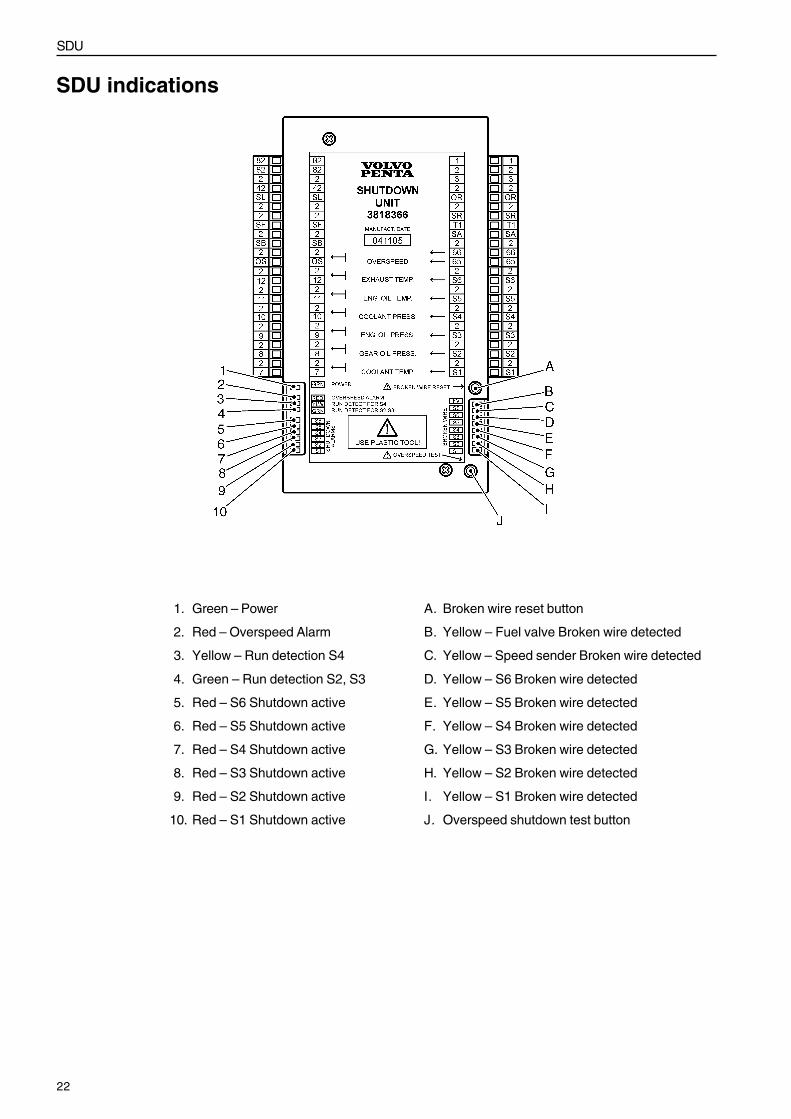
1. Green – Power
2. Red – Overspeed Alarm
3. Yellow – Run detection S4
4. Green – Run detection S2, S3
5. Red – S6 Shutdown active
6. Red – S5 Shutdown active
7. Red – S4 Shutdown active
8. Red – S3 Shutdown active
9. Red – S2 Shutdown active
10. Red – S1 Shutdown active
A. Broken wire reset button
B. Yellow – Fuel valve Broken wire detected
C. Yellow – Speed sender Broken wire detected
D. Yellow – S6 Broken wire detected
E. Yellow – S5 Broken wire detected
F. Yellow – S4 Broken wire detected
G. Yellow – S3 Broken wire detected
H. Yellow – S2 Broken wire detected
I. Yellow – S1 Broken wire detected
J. Overspeed shutdown test button
SDU indications
23
Installation
Installation notesFor detailed information on installation, refer to General arrangement drawing.
Power supplyIMPORTANT! Before connecting an MCU to its power supply or other external devices, always refer to Ge-neral Arrangement Drawing for detailed information concerning installation. When in doubt, contact VolvoPenta.
IMPORTANT! Wiring for binary inputs and analog inputs must not be lead parallel with high voltage/currentcables
IMPORTANT! Min. diam. of power supply cable should be 1.5 mm2.
IMPORTANT! Max. permissible continuous power supply voltage is 36 VDC.
IMPORTANT! Max permissible peak voltage is 39 VDC.
IMPORTANT! The MCU should be grounded properly in order to protect against atmospheric discharges.
Binary output protectionsIMPORTANT! Do not connect binary outputs directly to DC relays without protection diodes. Use protectiondiodes even if the relays are not connected directly to controller outputs.
NOTE! RB16 relays include protection diodes.
GroundingIMPORTANT! The shortest possible wire should be used when grounding the MCU.
IMPORTANT! Min. diam. of ground cable should be 2,5mm2.
IMPORTANT! The “-“ terminal of the battery has to be properly grounded.
Connection to engineFor information on connection of MCU to engine, refer to ”General arrangement drawing”.
24
Interface information
Wiring terminalsTerminal Comment
B+ ......................................................... BACKUP POWER SUPPLY
+24 V
2 ............................................................ BATTERY COMMON
0 V
A1 .......................................................... OIL PRESSURE
4-20 mA
A2 .......................................................... COOLANT PRESSURE
4-20 mA
A3 .......................................................... MAIN BATTERY VOLTAGE
A4 .......................................................... SECONDARY BATTERY VOLTAGE
A5, + - ................................................... FUEL PRESSURE
A6, + - ................................................... NOTE USED
Resistance
A7, + - ................................................... COOLANT TEMP
PT100
A8, + - ................................................... OIL TEMP
PT100
B1 .......................................................... SD COOLANT TEMP
SDU
B2 .......................................................... SD OIL PRESSURE
SDU
B4 .......................................................... SD OVERSPEED
SDU
B5 .......................................................... SD SYSTEM FAILURE
SDU
B6 .......................................................... SD OVERRIDE - AUX,EME,PRP
Active signal - Shorted to groundInactive signal - DisconnectedDisables all shutdowns except overspeed.
HARBOUR MODE - CMB
Active signal - Shorted to groundInactive signal - DisconnectedExternal switch between emergency and harbour mode.
B7 .......................................................... SPARE
B8 .......................................................... START BLOCKING
Active signal - Shorted to groundInactive signal - DisconnectedThe startblocking signal is used for the engine from start. An alarm willbe set if the engine is stopped and Startblocking signal is activated.
Interface information
25
Interface information
Terminal Comment
B9 .......................................................... ACKNOWLEDGE/FAULT RESET
Active signal - Shorted to groundInactive signal - DisconnectedAcknowledge alarms through external interface.
B10 ........................................................ COOLANT LEVEL SWITCH
Active signal - Shorted to groundInactive signal - DisconnectedFor coolant level alarm
B11 ........................................................ REMOTE START
Active signal - Shorted to groundInactive signal - DisconnectedFor remote start of the engine.
B12 ........................................................ REMOTE STOP
Active signal - Shorted to groundInactive signal - DisconnectedFor remote stop of the engine.
B13 ........................................................ BLACKOUT START - EME, AUX
Active signal - Shorted to groundInactive signal - DisconnectedStart signal for starting with serveral retries.
AUX mode - three start attempts.
EME mode - unlimited start attempts.
B14 ........................................................ FUEL LEAKAGE SWITCH
Active signal - Shorted to groundInactive signal - DisconnectedFor fuel leakage switch
BL ......................................................... BACKLIGHT FOR MCU Remote Panel
X1 .......................................................... SD OVERRIDE INDICATION - AUX, EME
Potential freeIndicates active Shutdown override.
HARBOUR MODE INDICATION - CMB
Indicates harbour mode.
X2 .......................................................... SPARE RELAY FUNCTION
NO or NC, refer to GA-drawing.
X3 .......................................................... SPARE RELAY FUNCTION
NO or NC, refer to GA-drawing.
X4 .......................................................... SPARE RELAY FUNCTION
NO or NC, refer to GA-drawing.
X5 .......................................................... MCU INTERNAL PROCESSOR (CPU) READY
Potential freeIndicates MCU active and system operational.
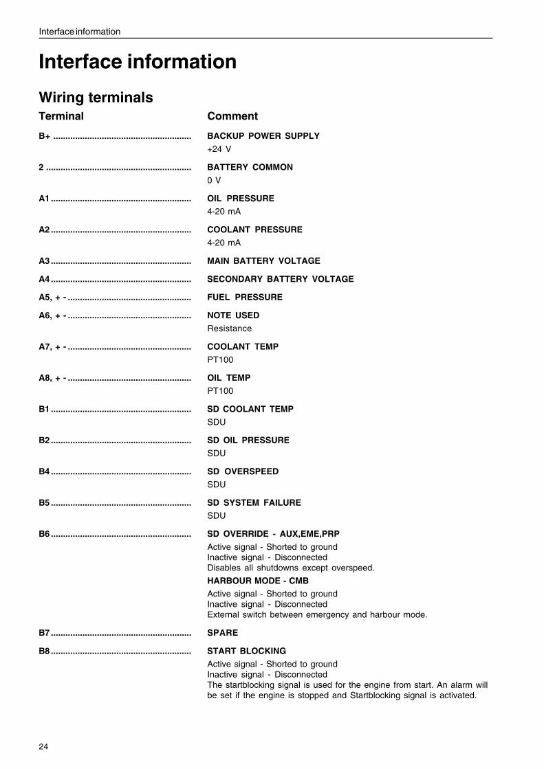
Relays X1 - X163. Normally Closed (NC)
2. Normally Open (NO)
1. Common
26
Interface information
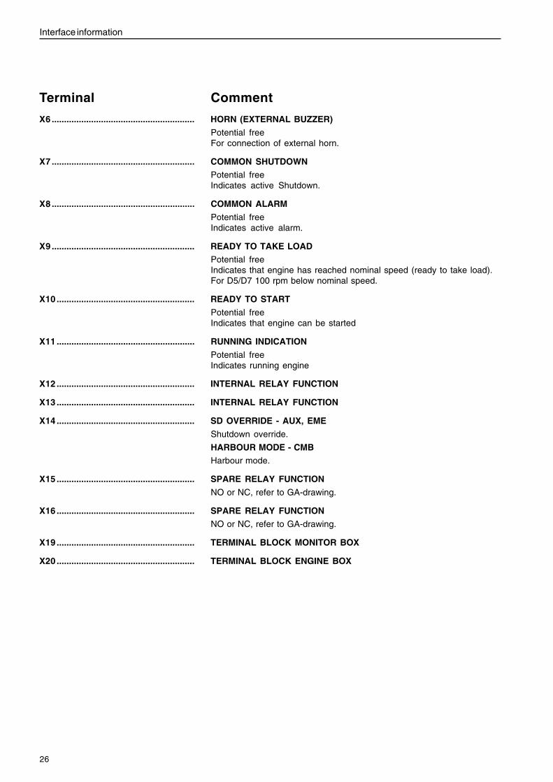
Terminal Comment
X6 .......................................................... HORN (EXTERNAL BUZZER)
Potential freeFor connection of external horn.
X7 .......................................................... COMMON SHUTDOWN
Potential freeIndicates active Shutdown.
X8 .......................................................... COMMON ALARM
Potential freeIndicates active alarm.
X9 .......................................................... READY TO TAKE LOAD
Potential freeIndicates that engine has reached nominal speed (ready to take load).For D5/D7 100 rpm below nominal speed.
X10 ........................................................ READY TO START
Potential freeIndicates that engine can be started
X11 ........................................................ RUNNING INDICATION
Potential freeIndicates running engine
X12 ........................................................ INTERNAL RELAY FUNCTION
X13 ........................................................ INTERNAL RELAY FUNCTION
X14 ........................................................ SD OVERRIDE - AUX, EME
Shutdown override.
HARBOUR MODE - CMB
Harbour mode.
X15 ........................................................ SPARE RELAY FUNCTION
NO or NC, refer to GA-drawing.
X16 ........................................................ SPARE RELAY FUNCTION
NO or NC, refer to GA-drawing.
X19 ........................................................ TERMINAL BLOCK MONITOR BOX
X20 ........................................................ TERMINAL BLOCK ENGINE BOX
27
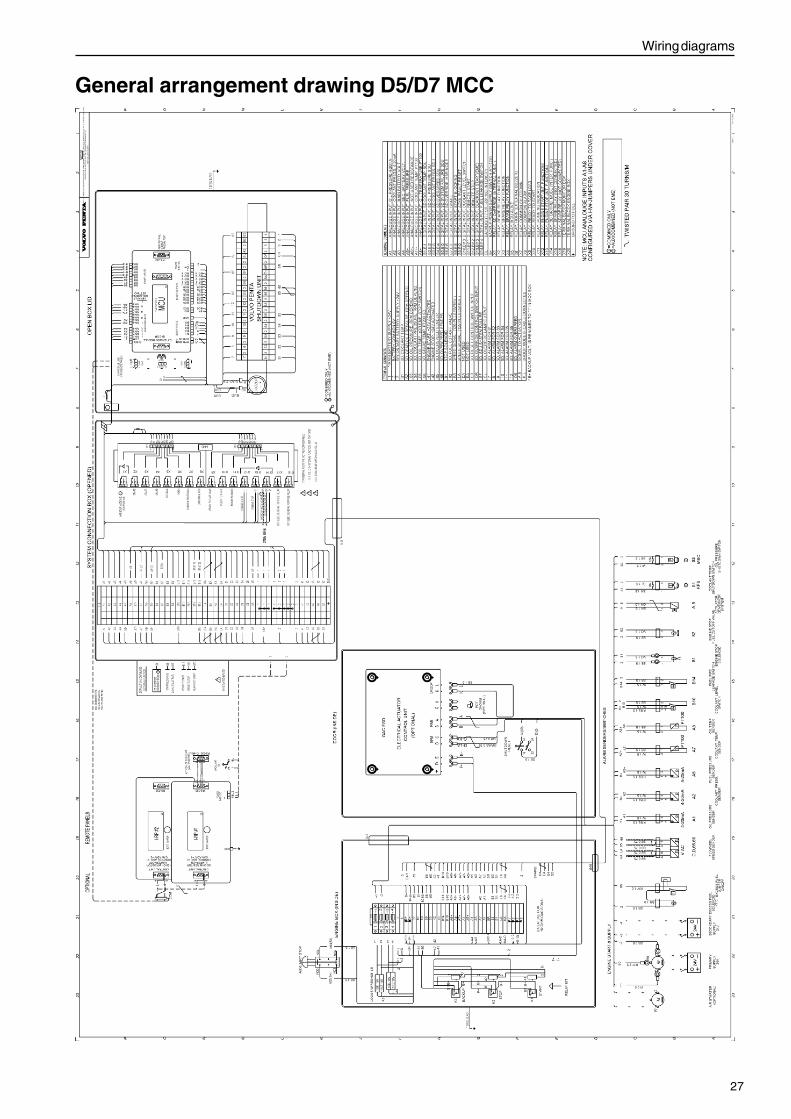
Wiring diagrams
General arrangement drawing D5/D7 MCC
28
Technical Data
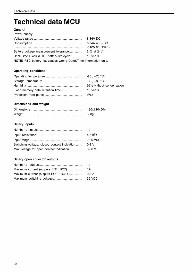
Technical data MCUGeneralPower supply
Voltage range ........................................................ 8-36V DC
Consumption .......................................................... 0,34A at 8VDC............................................................................... 0,12A at 24VDC
Battery voltage measurement tolerance ............... 2 % at 24V
Real Time Clock (RTC) battery life-cycle ............. 10 years
NOTE! RTC battery flat causes wrong Date&Time information only.
Operating conditions
Operating temperature ........................................... -20 ¸ +70 °C
Storage temperature .............................................. -30 ¸ +80 °C
Humidity ................................................................. 95% without condensation
Flash memory data retention time ........................ 10 years
Protection front panel ............................................ IP65
Dimensions and weight
Dimensions ............................................................ 180x120x50mm
Weight .................................................................... 800g
Binary inputs
Number of inputs ................................................... 14
Input resistance ..................................................... 4.7 kΩInput range ............................................................. 0-36 VDC
Switching voltage, closed contact indication ....... 0-2 V
Max voltage for open contact indication ............... 8-36 V
Binary open collector outputs
Number of outputs ................................................. 14
Maximum current (outputs BO1, BO2) ................. 1A
Maximum current (outputs BO3 - BO14) .............. 0,5 A
Maximum switching voltage .................................. 36 VDC
29
Technical Data
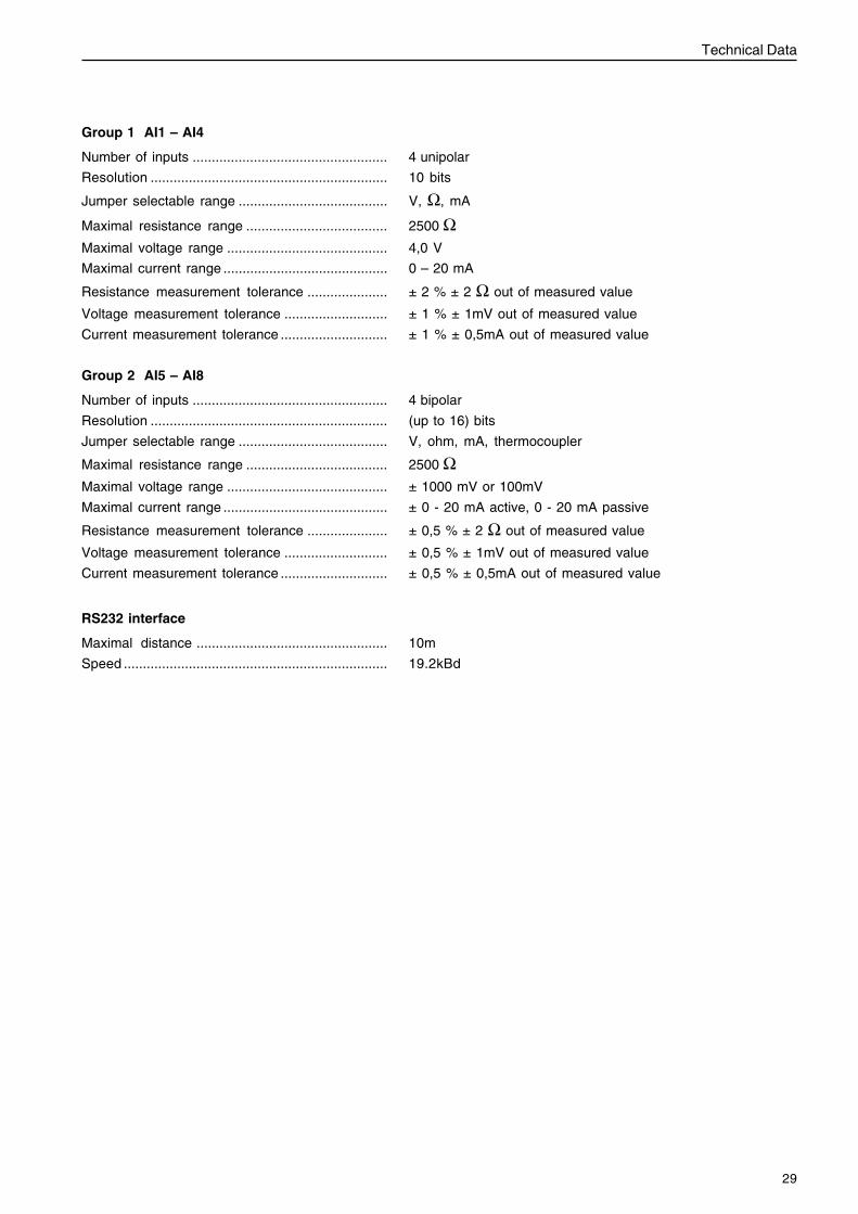
Group 1 AI1 – AI4
Number of inputs ................................................... 4 unipolar
Resolution .............................................................. 10 bits
Jumper selectable range ....................................... V, Ω, mA
Maximal resistance range ..................................... 2500 ΩMaximal voltage range .......................................... 4,0 V
Maximal current range ........................................... 0 – 20 mA
Resistance measurement tolerance ..................... ± 2 % ± 2 Ω out of measured value
Voltage measurement tolerance ........................... ± 1 % ± 1mV out of measured value
Current measurement tolerance ............................ ± 1 % ± 0,5mA out of measured value
Group 2 AI5 – AI8
Number of inputs ................................................... 4 bipolar
Resolution .............................................................. (up to 16) bits
Jumper selectable range ....................................... V, ohm, mA, thermocoupler
Maximal resistance range ..................................... 2500 ΩMaximal voltage range .......................................... ± 1000 mV or 100mV
Maximal current range ........................................... ± 0 - 20 mA active, 0 - 20 mA passive
Resistance measurement tolerance ..................... ± 0,5 % ± 2 Ω out of measured value
Voltage measurement tolerance ........................... ± 0,5 % ± 1mV out of measured value
Current measurement tolerance ............................ ± 0,5 % ± 0,5mA out of measured value
RS232 interface
Maximal distance .................................................. 10m
Speed ..................................................................... 19.2kBd


7745
526
Eng
lish
04-2
005