Embed Size (px)
Citation preview
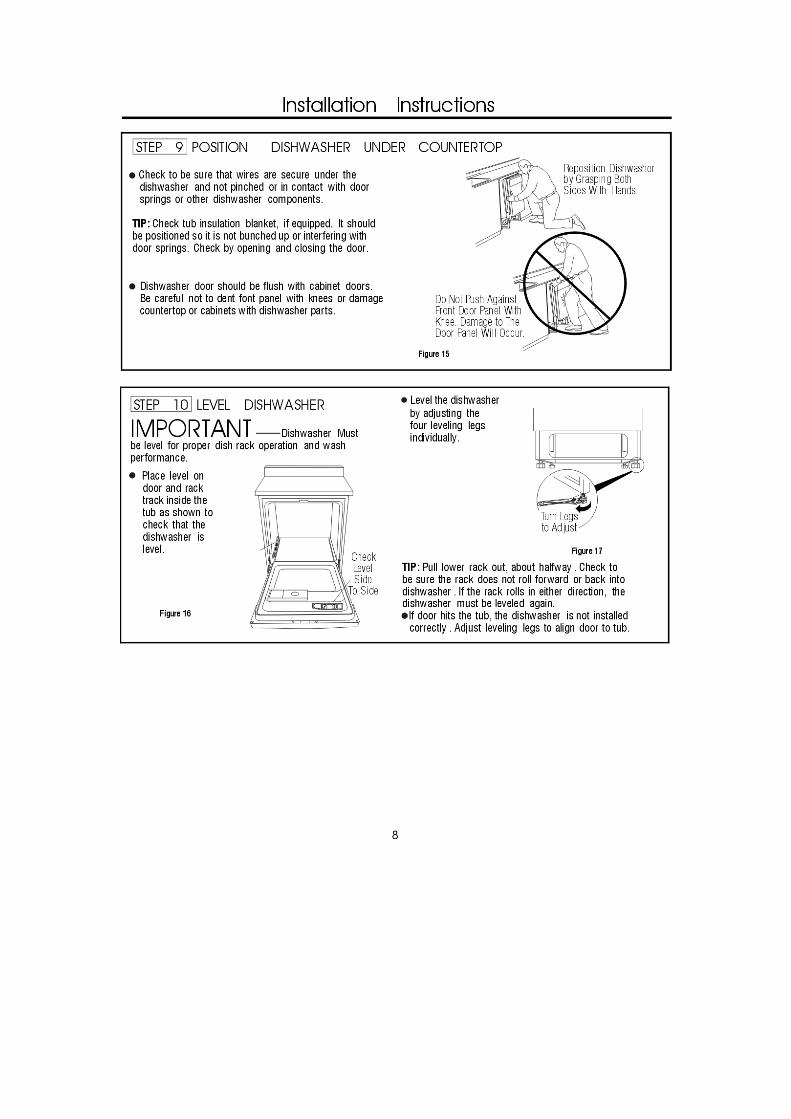
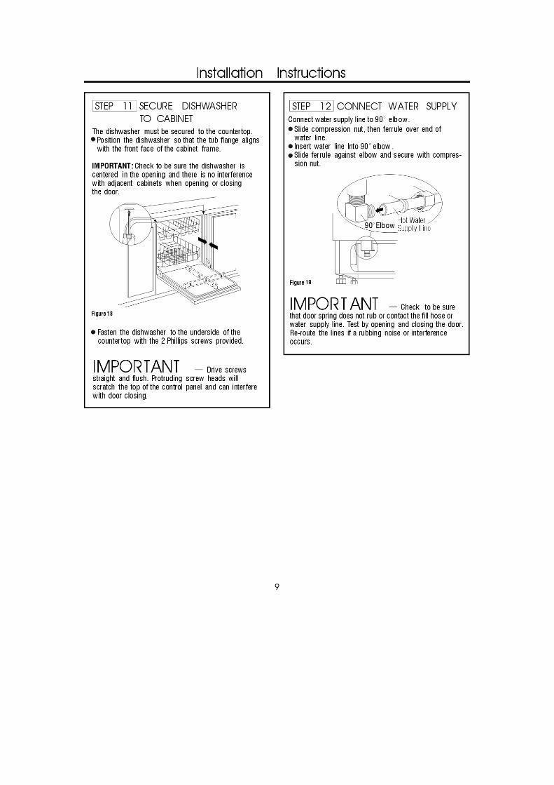
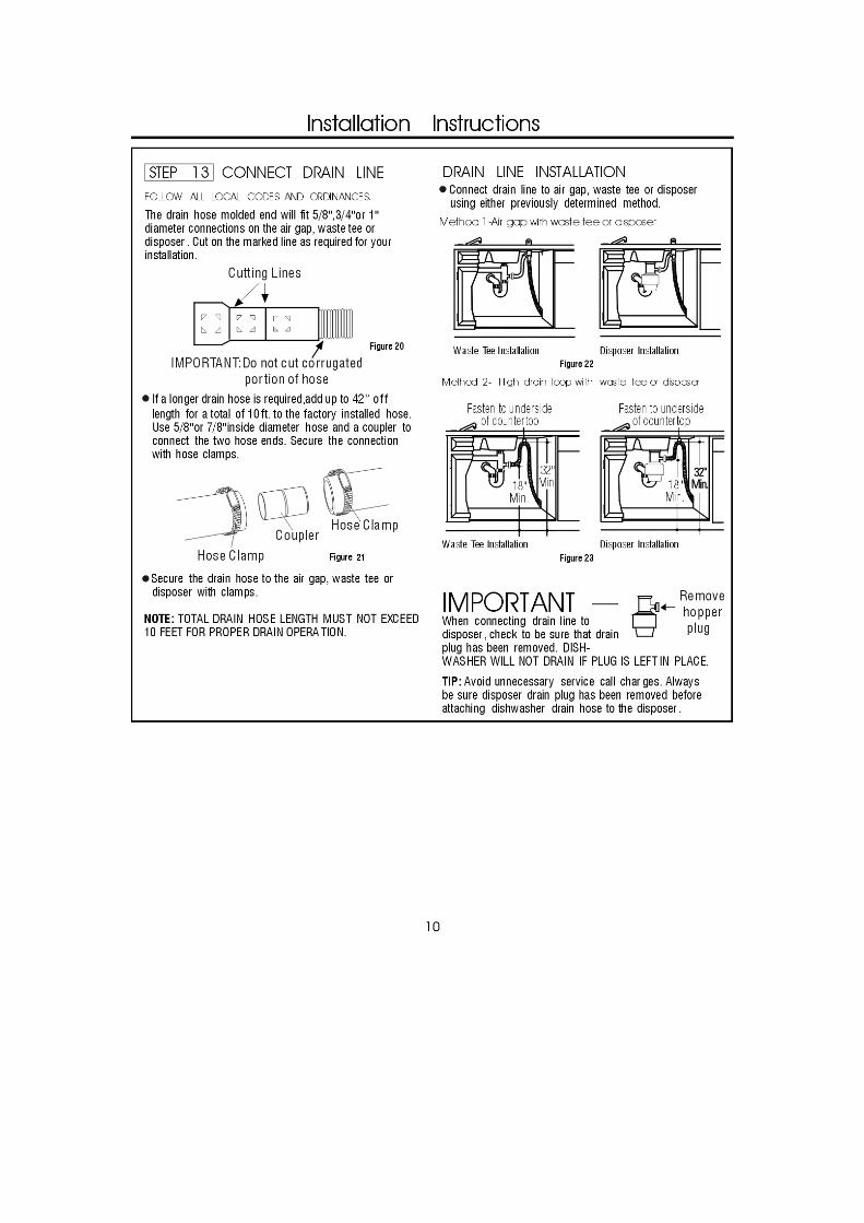
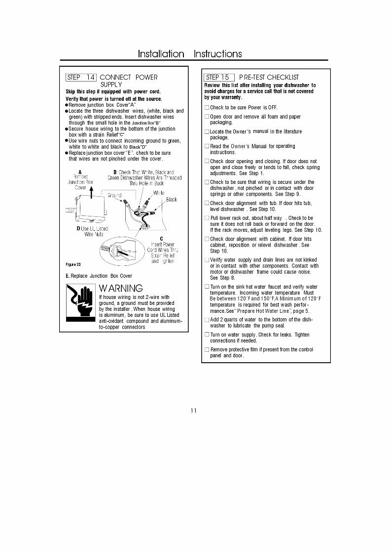
InstallationInstructions
Built-InDishwasher
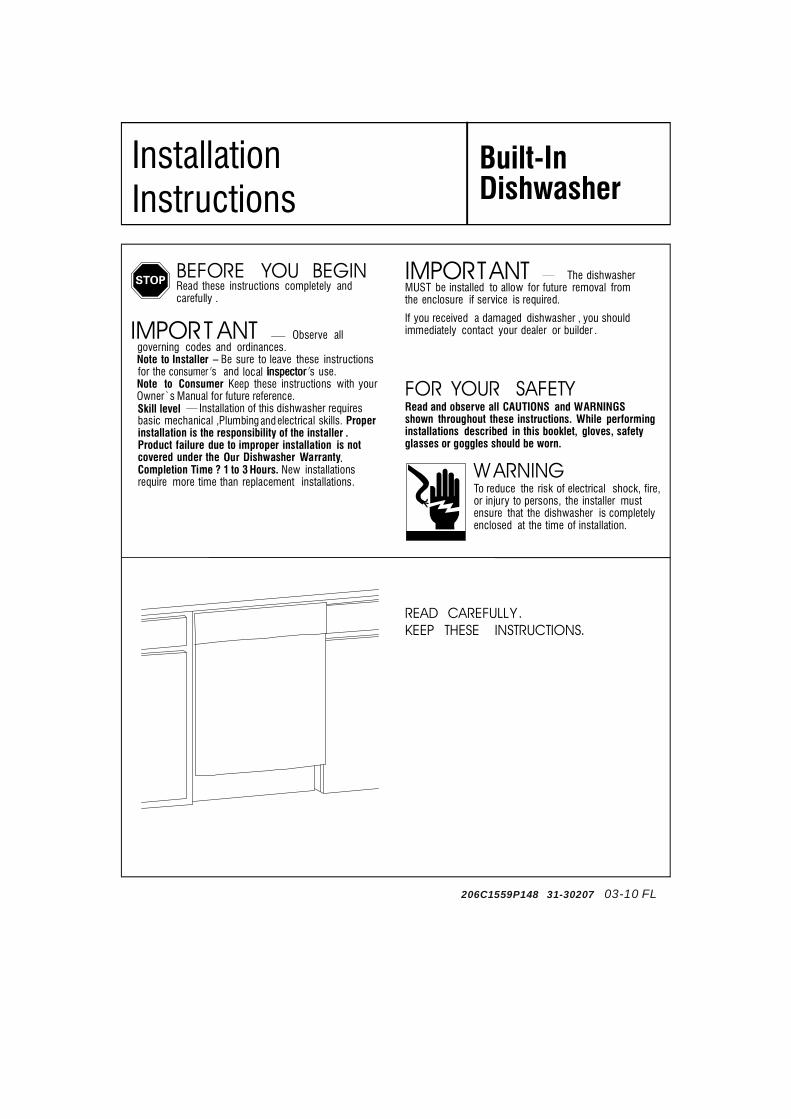
IMPORTANT The dishwasherMUST be installed to allow for future removal fromthe enclosure if service is required.
If you received a damaged dishwasher , you shouldimmediately contact your dealer or builder .
FOR YOUR SAFETYRead and observe all CAUTIONS and WARNINGSshown throughout these instructions. While performinginstallations described in this booklet, gloves, safetyglasses or goggles should be worn.
BEFORE YOU BEGINRead these instructions completely andcarefully .
IMPORT ANT Observe allgoverning codes and ordinances.Note to Installer –� Be sure to leave these instructionsfor the and local inspector �Inspector s′ use.Note to Consumer Keep these instructions with yourOwner`s Manual for future reference.
Installation of this dishwasher requiresbasic mechanical and electrical skills. Properinstallation is the responsibility of the installer .Product failure due to improper installation is notcovered under the Dishwasher WarrantyCompletion Time ? 1 to 3 Hours. New installationsrequire more time than replacement installations.
READ CAREFULLY.KEEP THESE INSTRUCTIONS.
W ARNINGTo reduce the risk of electrical shock, fire,or injury to persons, the installer mustensure that the dishwasher is completelyenclosed at the time of installation.
—
Skill level —,Plumbing
206C1559P148 31-30207 03-10 FL
Installation Preparation
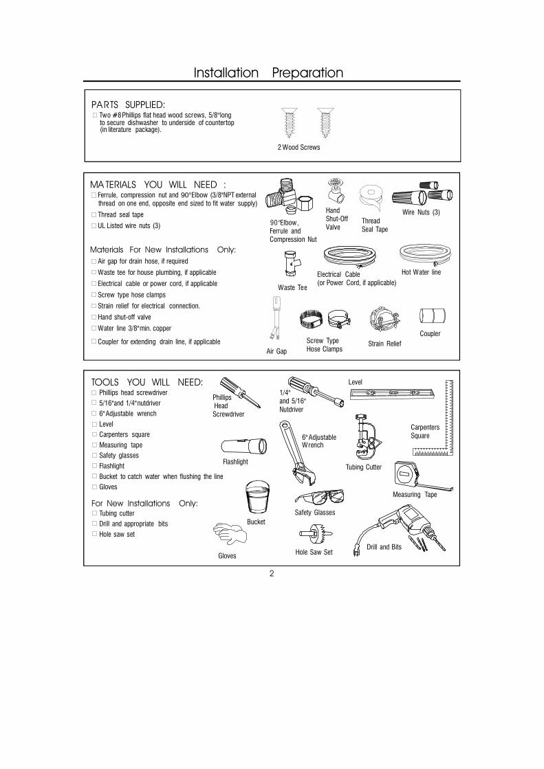
PARTS SUPPLIED: Two #8 Phillips flat head wood screws, 5/8" longto secure dishwasher to underside of countertop(in literature package).
MA TERIALS YOU WILL NEED : Ferrule, compression nut and 90°Elbow (3/8"NPT externalthread on one end, opposite end sized to fit water supply)
Thread seal tape
UL Listed wire nuts (3)
Materials For New Installations Only: Air gap for drain hose, if required
Waste tee for house plumbing, if applicable
Electrical cable or power cord, if applicable
Screw type hose clamps
Strain relief for electrical connection.
Hand shut-off valve
Water line 3/8" min. copper
Coupler for extending drain line, if applicable
TOOLS YOU WILL NEED: Phillips head screwdriver 5/16" and 1/4" nutdriver 6" Adjustable wrench Level Carpenters square
Measuring tape Safety glasses Flashlight
Bucket to catch water when flushing the line Gloves
For New Installations Only: Tubing cutter Drill and appropriate bits Hole saw set
Elbow,Ferrule andCompression Nut
Wire Nuts (3)
Waste Tee
Electrical Cable(or Power Cord, if applicable)
Hot Water line
Screw TypeHose Clamps
Coupler
HandShut-OffValve
2 Wood Screws
Hole Saw Set
Measuring Tape
Tubing Cutter
Drill and Bits
Phillips HeadScrewdriver
1/4"and 5/16"Nutdriver
Safety Glasses
6" AdjustableWrench
Bucket
Flashlight
Gloves
CarpentersSquare
Level
2
ThreadSeal Tape
Air GapStrain Relief
90°
Installation Preparation
3
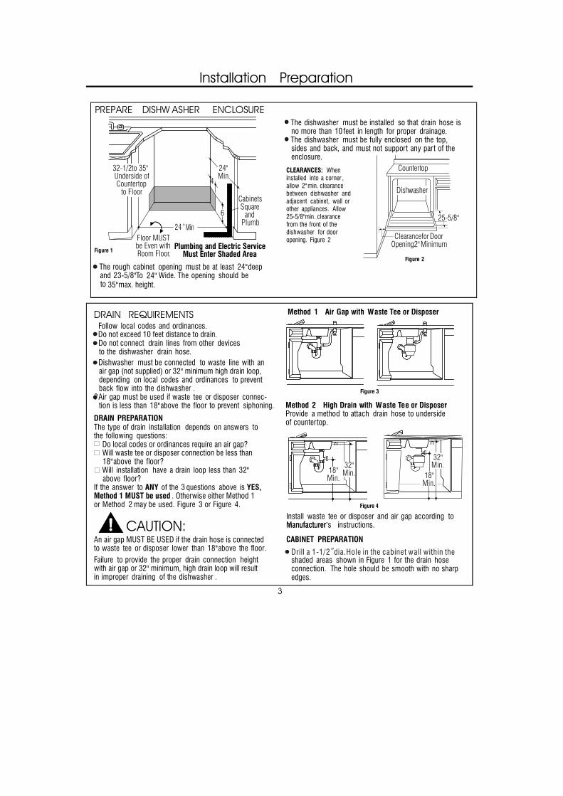
PREPARE DISHW ASHER ENCLOSURE
The rough cabinet opening must be at least 24" deepand 23-5/8" To Wide. The opening should be to 35" max. height.
The dishwasher must be installed so that drain hose isno more than 10 feet in length for proper drainage.The dishwasher must be fully enclosed on the top,sides and back, and must not support any part of theenclosure.
CLEARANCES: Wheninstalled into a corner ,allow 2" min. clearancebetween dishwasher andadjacent cabinet, wall orother appliances. Allow25-5/8" min. clearancefrom the front of thedishwasher for dooropening. Figure 2
DRAIN REQUIREMENTSFollow local codes and ordinances.
Do not connectDo not exceed 10 feet distance to drain.
drain lines from other devicesto the dishwasher drain hose.Dishwasher must be connected to waste line with anair gap (not supplied) or 32" minimum high drain loop,depending on local codes and ordinances to preventback flow into the dishwasher .
?Air gap must be used if waste tee or disposer connec-tion is less than 18" above the floor to prevent siphoning.
DRAIN PREPARATIONThe type of drain installation depends on answers tothe following questions:
Do local codes or ordinances require an air gap? Will waste tee or disposer connection be less than18" above the floor?
Will installation have a drain loop less than 32"above floor?
If the answer to ANY of the 3 questions above is YES,Method 1 MUST be used . Otherwise either Method 1or Method 2 may be used. Figure 3 or Figure 4.
CAUTION:An air gap MUST BE USED if the drain hose is connectedto waste tee or disposer lower than 18" above the floor.Failure to provide the proper drain connection heightwith air gap or 32" minimum, high drain loop will resultin improper draining of the dishwasher .
Figure 1
Figure 2
Figure 3
Figure 4
4
6
CabinetsSquare
andPlumb
Floor MUSTbe Even withRoom Floor.
Plumbing and Electric ServiceMust Enter Shaded Area
32-1/2to 35"Underside ofCountertop
to Floor
24" Min.
Clearance for DoorOpening 2" Minimum
Countertop
Dishwasher
25-5/8"
Note: Llation,
(32-1/2") countertops may by the andleveling legs.
18"Min.
32"Min.
32"Min.
18"Min.
Install waste tee or disposer and air gap according tomanufacturer �Manufacturer s’ instructions.
CABINET PREPARATION
shaded areas shown in Figure 1 for the drain hoseconnection. The hole should be smooth with no sharpedges.
Method 1 Air Gap with Waste Tee or Disposer
Method 2 High Drain with Waste Tee or DisposerProvide a method to attach drain hose to undersideof countertop.
24"
·
18"Min.
Drill a 1-1/2 dia.Hole in the cabinet wall within the
Installation Preparation
4
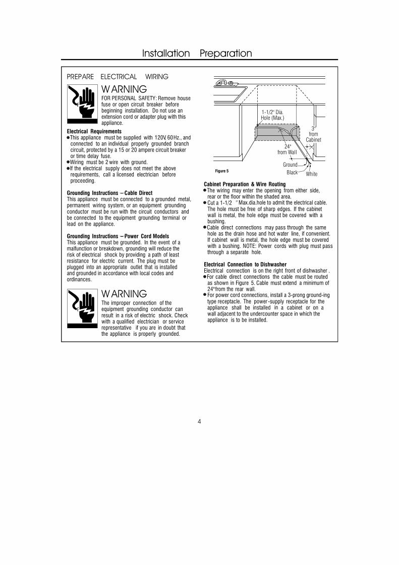
Cabinet Preparation & Wire RoutingThe wiring may enter the opening from either side,rear or the floor within the shaded area.
The hole must be free of sharp edges. If the cabinetwall is metal, the hole edge must be covered with abushing.Cable direct connections may pass through the samehole as the drain hose and hot water line, if convenient.If cabinet wall is metal, the hole edge must be coveredwith a bushing. NOTE: Power cords with plug must passthrough a separate hole.
Electrical Connection to DishwasherElectrical connection is on the right front of dishwasher .
For cable direct connections the cable must be routedas shown in Figure 5. Cable must extend a minimum of24" from the rear wall.
The power -supply receptacle for the appliance shall be installed in a cabinet or on awall adjacent to the undercounter space in which theappliance is to be installed.
Figure 5
W ARNINGFOR PERSONAL SAFETY: Remove housefuse or open circuit breaker beforebeginning installation. Do not use anextension cord or adapter plug with thisappliance.
PREPARE ELECTRICAL WIRING
Electrical RequirementsThis appliance must be supplied with 120V, 60 Hz., andconnected to an individual properly grounded branchcircuit, protected by a 15 or 20 ampere circuit breakeror time delay fuse.Wiring must be 2 wire with ground.If the electrical supply does not meet the aboverequirements, call a licensed electrician beforeproceeding.
Grounding Instructions —–� Cable DirectThis appliance must be connected to a grounded metal,permanent wiring system, or an equipment groundingconductor must be run with the circuit conductors andbe connected to the equipment grounding terminal orlead on the appliance.
Grounding Instructions —–� Power Cord ModelsThis appliance must be grounded. In the event of amalfunction or breakdown, grounding will reduce therisk of electrical shock by providing a path of leastresistance for electric current. The plug must beplugged into an appropriate outlet that is installedand grounded in accordance with local codes andordinances.
W ARNINGThe improper connection of theequipment grounding conductor canresult in a risk of electric shock. Checkwith a qualified electrician or servicerepresentative if you are in doubt thatthe appliance is properly grounded.
White
24"from Wall
3"from
Cabinet
GroundBlack
1-1/2" Dia.Hole (Max.)
Cut a 1-1/2 ″
For power cord connections, install a 3-prong ground-ing type receptacle.
Max.dia.hole to admit the electrical cable.
Installation Instructions
5
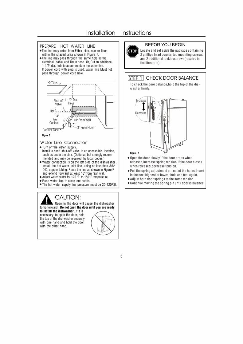
PREPARE BEFOR YOU BEGIN HOT W ATER LINEThe line may enter from Either side, rear or floorwithin the shaded area shown in Figure F.The line may pass through the same hole as theelectrical cable and Drain hose. Or, Cut an additional1-1/2" dia. hole to accommodate the water line.If power cord with plug is used, water line Must notpass through power cord hole.
Figure 6
W ater Line Connection
CHECK DOOR BALANCE
Turn off the water supply.Install a hand shut-off valve in an accessible location,such as under the sink. (Optional, but strongly recom-mended and may be required by local codes.)Water connection is on the left side of the dishwasher .Install the hot water inlet line, using no less than 3/8"O.D. copper tubing. Route the line as shown in Figure Fand extend forward at least 18" from rear wall.
Flush water line to clean out debris.The hot water supply line pressure must be 20-120 PSI.
CAUTION:Opening the door will cause the dishwasher
to tip forward. Do not open the door until you are readyto install the dishwasher . If it isnecessary to open the door, holdthe top of the dishwasher securelywith one hand and hold the doorwith the other hand.
?Open the door slowly, if the door drops whenreleased, increase Spring tension. If the door closeswhen released, decrease tension.
?Pull pin of the in or
? both the ?Continue the spring until door Is balanced.
Twasher firmly.
Figure G
Locate set aside 2 Phillips screwsand 2 inthe literature package).
·
Locate and set aside the package containing 2 phillips head counter top mounting screws and 2 additional toekickscrews(located in the li terature).
Open the door slowly,if the door drops when released,increase spring tension.If the door closeswhen released,decrease tension.
Figure 7
Pull the spring adjustment pin out of the holes,inser tin the next highest or lowest hole and test again.Adjust both door springs to the same tension.Continue moving the spring pin until door is balance.
·
··
To check the door balance,hold the top of the dis-washer firmly.
Installation Instructions
STEP 16 DISHWASHER WET TEST
Turn on power supply(or plug power cord into outlet, if equipped).
Select Normal wash program.″ ″
Close the door.
Check to be sure that water enters the dishwasher.If water does not enter the dishwasher,check to be sure that water and power are turn on.
Check for leaks under the dishwasher.If a leak is found,turn power supply off,then tighten connections.Restore power af terleak is corrected.
Check for leaks.around the door. A leak around the door could be caused by door rubbing or hitting against adjacent cabinetry. Reposition the dishwasher if necessary.See step 9.
The dishwasher wil l drain and turn off about 5 to 7 minutes af ter the first fill .Check dain l ines.If leaks are found,turn power off at the breaker and correct plumbing as necessary.Restore power ater corrections are made.See Step 12.
Open dishwasher door and make sure most of the water has drained.If not ,check that disposer plug has beenremoved and/or air gap is not p lugged.See Step 13.Also chek drain line for kinking.
Run the dishwasher through another fi ll and drain cycle .Check for leaks and correct if require.At the end of drain, Press reset button.
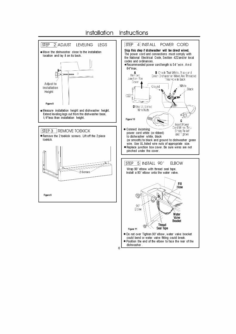
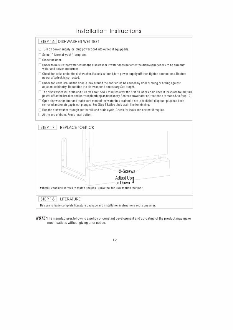
STEP 17 REPLACE TOEKICK
·Install 2 toekick screws to fasten toekick. Allow the toe kick to tuch the floor.
STEP 18 LITERATURE
Be sure to leave complete literature package and instal lation instructions with consumer.
12
NOTE:The manufacturer,following a policy of constant development and up-dating of the product,may make modifications without giving prior notice.
Adjust Upor Down
2-Screws