Embed Size (px)
Citation preview

QUALITY ASSURANCE/QUALITY CONTROL DOCUMENTATION SERIES
TITLE INSTALLATION AND SITE DOCUMENTATION FOR OPTICALMONITORING EQUIPMENT
TYPE STANDARD OPERATING PROCEDURE
NUMBER 4070
DATE JULY 1996
AUTHORIZATIONS
TITLE NAME SIGNATURE
ORIGINATOR Gloria S. Mercer
PROJECT MANAGER James H. Wagner
PROGRAM MANAGER David L. Dietrich
QA MANAGER Gloria S. Mercer
OTHER
REVISION HISTORY
REVISIONNO.
CHANGEDESCRIPTION
DATE AUTHORIZATIONS

Number 4070Revision 0Date JUL 1996Page i of i
TABLE OF CONTENTS
Section Page
1.0 PURPOSE AND APPLICABILITY 1
2.0 RESPONSIBILITIES 1
2.1 Program Manager 12.2 Project Manager 12.3 Field Specialist 22.4 Data Analyst 22.5 Local (On-Site) Contact 2
3.0 REQUIRED EQUIPMENT AND MATERIALS 3
3.1 Equipment and Materials Required for Nephelometer Installations 33.2 Equipment and Materials Required for Transmissometer Installations 3
4.0 METHODS 5
4.1 Site Preparation and Communication 54.2 Installation Methods and Procedures 64.3 Operator Training 64.4 Site Documentation and Documentation Archival 6

Number 4070Revision 0Date JUL 1996Page 1 of 6
1.0 PURPOSE AND APPLICABILITY
This standard operating procedure (SOP) outlines the general procedures regardinginstallation and site documentation of optical monitoring instrumentation operated according toIMPROVE Protocol. Optical monitoring sites include those equipped with an Optec LPVtransmissometer and/or Optec NGN nephelometer.
To assure quality data capture and minimize data loss, site installation and documentationprocedures include:
• Installing the instrumentation, shelters, and support components in a standardconfiguration to ease data collection, troubleshooting, and servicing.
• Performing thorough on-site specification measurements.
• Documenting site specification measurements and other site-related information.
The following technical instructions provide detailed information regarding installing opticalmonitoring equipment or documenting optical site information:
• TI 4070-3000 Installation of Optec NGN-2 Nephelometer Systems (IMPROVEProtocol)
• TI 4070-3001 Site Documentation for Optec NGN-2 Nephelometer Systems
• TI 4070-3010 Installation and Site Documentation for Optec LPV-2Transmissometer Systems (IMPROVE Protocol)
2.0 RESPONSIBILITIES
2.1 PROGRAM MANAGER
The program manager shall review site preparation, installation requirements, and theinstallation schedule with the project manager.
2.2 PROJECT MANAGER
The project manager shall:
• Review site preparation, installation requirements, and the installation schedule with theprogram manager and/or the project-specific Contracting Officer's TechnicalRepresentative (COTR) as required.
• Schedule the system installation.
• Review final site configuration plans presented by the field specialist.
• Review the completed site documentation forms for completeness and accuracy.

Number 4070Revision 0Date JUL 1996Page 2 of 6
2.3 FIELD SPECIALIST
The field specialist shall:
• Review the installation with the project manager.
• Coordinate with on-site personnel regarding the installation location, schedule,installation assistance, and availability of materials.
• Ship all required equipment to the site.
• Install the optical systems.
• Perform an installation calibration or field audit.
• Schedule and conduct an operator training session.
• Complete all site documentation.
• Provide completed site documentation to the data analyst.
2.4 DATA ANALYST
The data analyst shall:
• Verify transmission of data from the system upon completion of the installation.
• Enter all site documentation into the Quality Assurance Database.
• File all hard copy site documentation provided by the field specialist.
2.5 LOCAL (ON-SITE) CONTACT
The local contact shall:
• Review site preparation and installation requirements with the field specialist.
• Identify and contact local landowners, land managers, primary contacts, and siteoperators regarding site installation and routine maintenance requirements.
• Perform or ensure completion of any site preparation required prior to the installation.
• Assist in obtaining any site-, installation-, and regular servicing-related clearances andpermits.
• Provide on-site equipment and tools required during the installation.
• As required, provide assistance with the installation.
• Schedule the operator training session with pertinent routine servicing personnel and thefield specialist.

Number 4070Revision 0Date JUL 1996Page 3 of 6
3.0 REQUIRED EQUIPMENT AND MATERIALS
3.1 EQUIPMENT AND MATERIALS REQUIRED FOR NEPHELOMETERINSTALLATIONS
• Optec NGN-2 ambient nephelometer with extra lamps
• Rohn tower, base plate, and hardware
• Solar radiation and precipitation shield
• Precipitation hood
• Nephelometer datalogging and support subsystem
• Span gas calibration system
• Ambient air temperature and relative humidity sensor in force-aspirated shield
• AC power line and telephone line
• Complete set of installation tools
• A camera loaded with color print film
• Laptop computer equipped with PROCOMM
• Replacement connector kit
• Telephone line simulator
• Topographic maps of the area
• Information documented during the site selection process
• NGN-2 Nephelometer Site Documentation Form
• Site Operator's Manual for Nephelometer Systems
• Complete set of standard operating procedures and technical instructions regardingannual site visit procedures, calibration of monitoring systems, replacing and shippingoptical components, monitoring system diagrams, site documentation, and operatormaintenance procedures
• Pen or pencil
3.2 EQUIPMENT AND MATERIALS REQUIRED FOR TRANSMISSOMETERINSTALLATIONS
• Installation transmissometer with calibrated lamps

Number 4070Revision 0Date JUL 1996Page 4 of 6
• Audit transmissometer with calibrated lamps
• Programmed data collection platform (DCP) with antenna, antenna cable, and solarpanel charging system or AC-trickle charger
• AT/RH sensor with housing and cable
• Strip chart recorder and supplies
• Electronic distance meter (EDM) with mirror assembly and tripods
• Receiver and transmitter shelters with anchor assemblies
• Receiver and transmitter mounting posts and alti-azimuth bases
• Window/hood assemblies
• Terminal strip board
• Power supplies and/or solar panel assemblies
• Metal shelves for larger shelters
• Shelter anchor assemblies
• Deep-cycle batteries for solar-powered installations
• Hardware for shelter assembly, post installation, and miscellaneous installation-relatedtasks
• Miscellaneous servicing supplies, as detailed in TI 4115-3000, Annual Site VisitProcedures for Optec LPV-2 Transmissometer Systems (IMPROVE Protocol), TI 4110-3100, Routine Site Operator Maintenance Procedures for LPV-2 TransmissometerSystems (IMPROVE Protocol), and TI 4110-3300, Troubleshooting and EmergencyMaintenance Procedures for Optec LPV-2 Transmissometer Systems (IMPROVEProtocol)
• Concrete mix
• Caulking
• Rock/concrete epoxy capsules
• Surge protectors
• Solar panel regulators
• Dust pan, brushes, and broom
• AC or battery jigsaw with wood and metal blades
Number 4070Revision 0Date JUL 1996Page 5 of 6
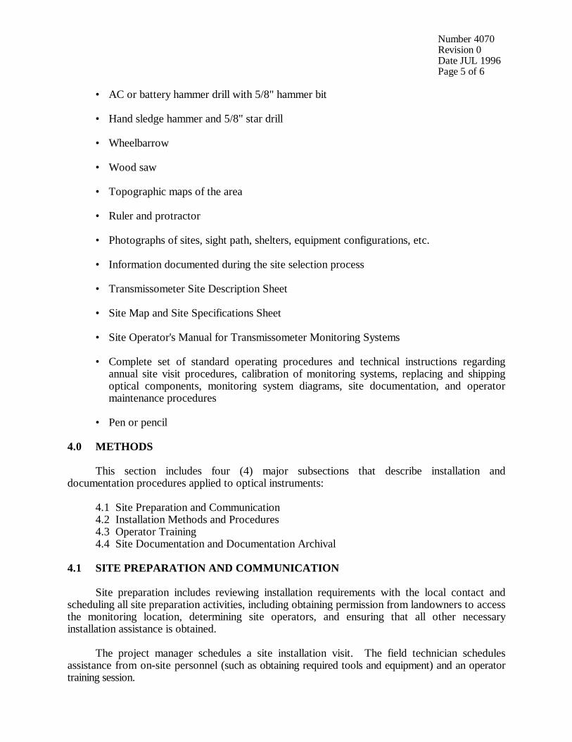
• AC or battery hammer drill with 5/8" hammer bit
• Hand sledge hammer and 5/8" star drill
• Wheelbarrow
• Wood saw
• Topographic maps of the area
• Ruler and protractor
• Photographs of sites, sight path, shelters, equipment configurations, etc.
• Information documented during the site selection process
• Transmissometer Site Description Sheet
• Site Map and Site Specifications Sheet
• Site Operator's Manual for Transmissometer Monitoring Systems
• Complete set of standard operating procedures and technical instructions regardingannual site visit procedures, calibration of monitoring systems, replacing and shippingoptical components, monitoring system diagrams, site documentation, and operatormaintenance procedures
• Pen or pencil
4.0 METHODS
This section includes four (4) major subsections that describe installation anddocumentation procedures applied to optical instruments:
4.1 Site Preparation and Communication4.2 Installation Methods and Procedures4.3 Operator Training4.4 Site Documentation and Documentation Archival
4.1 SITE PREPARATION AND COMMUNICATION
Site preparation includes reviewing installation requirements with the local contact andscheduling all site preparation activities, including obtaining permission from landowners to accessthe monitoring location, determining site operators, and ensuring that all other necessaryinstallation assistance is obtained.
The project manager schedules a site installation visit. The field technician schedulesassistance from on-site personnel (such as obtaining required tools and equipment) and an operatortraining session.
Number 4070Revision 0Date JUL 1996Page 6 of 6
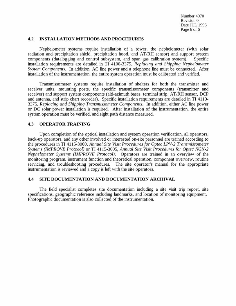
4.2 INSTALLATION METHODS AND PROCEDURES
Nephelometer systems require installation of a tower, the nephelometer (with solarradiation and precipitation shield, precipitation hood, and AT/RH sensor) and support systemcomponents (datalogging and control subsystem, and span gas calibration system). Specificinstallation requirements are detailed in TI 4100-3375, Replacing and Shipping NephelometerSystem Components. In addition, AC line power and a telephone line must be connected. Afterinstallation of the instrumentation, the entire system operation must be calibrated and verified.
Transmissometer systems require installation of shelters for both the transmitter andreceiver units, mounting posts, the specific transmissometer components (transmitter andreceiver) and support system components (alti-azimuth bases, terminal strip, AT/RH sensor, DCPand antenna, and strip chart recorder). Specific installation requirements are detailed in TI 4110-3375, Replacing and Shipping Transmissometer Components. In addition, either AC line poweror DC solar power installation is required. After installation of the instrumentation, the entiresystem operation must be verified, and sight path distance measured.
4.3 OPERATOR TRAINING
Upon completion of the optical installation and system operation verification, all operators,back-up operators, and any other involved or interested on-site personnel are trained according tothe procedures in TI 4115-3000, Annual Site Visit Procedures for Optec LPV-2 TransmissometerSystems (IMPROVE Protocol) or TI 4115-3005, Annual Site Visit Procedures for Optec NGN-2Nephelometer Systems (IMPROVE Protocol). Operators are trained in an overview of themonitoring program, instrument function and theoretical operation, component overview, routineservicing, and troubleshooting procedures. The site operator's manual for the appropriateinstrumentation is reviewed and a copy is left with the site operators.
4.4 SITE DOCUMENTATION AND DOCUMENTATION ARCHIVAL
The field specialist completes site documentation including a site visit trip report, sitespecifications, geographic reference including landmarks, and location of monitoring equipment. Photographic documentation is also collected of the instrumentation.

QUALITY ASSURANCE/QUALITY CONTROL DOCUMENTATION SERIES
TITLE INSTALLATION AND SITE DOCUMENTATION FOR OPTEC LPV-2TRANSMISSOMETER SYSTEMS (IMPROVE PROTOCOL)
TYPE TECHNICAL INSTRUCTION
NUMBER 4070-3010
DATE FEBRUARY 1994
AUTHORIZATIONS
TITLE NAME SIGNATURE
ORIGINATOR Ivar J. Rennat
PROJECT MANAGER James H. Wagner
PROGRAM MANAGER David L. Dietrich
QA MANAGER Gloria S. Mercer
OTHER
REVISION HISTORY
REVISIONNO.
CHANGEDESCRIPTION
DATE AUTHORIZATIONS
0.1 Minor text changes and updated format. July 1996
Number 4070-3010Revision 0.1Date JUL 1996Page i of ii
TABLE OF CONTENTS
Section Page
1.0 PURPOSE AND APPLICABILITY 1
2.0 RESPONSIBILITIES 1
2.1 Program Manager 12.2 Project Manager 12.3 Field Specialist 22.4 Data Analyst 22.5 Local (On-Site) Contact 2
3.0 REQUIRED EQUIPMENT AND MATERIALS 3
3.1 Instrumentation 33.2 Equipment Configurations 33.3 Tools 53.4 Installation Materials 63.5 Site Documentation Materials 6
4.0 METHODS 7
4.1 Site Preparation and Communication 74.2 Mounting Post Installation 94.3 Shelter Transportation and Installation 134.4 Line-Power (AC) and Solar Power (DC) System Installation 144.5 Installation of Instrumentation 174.6 Sight Path Distance Measurement 224.7 System Operation Verification 224.8 Operator Training 224.9 Site Documentation and Documentation Archival 22
5.0 REFERENCES 26
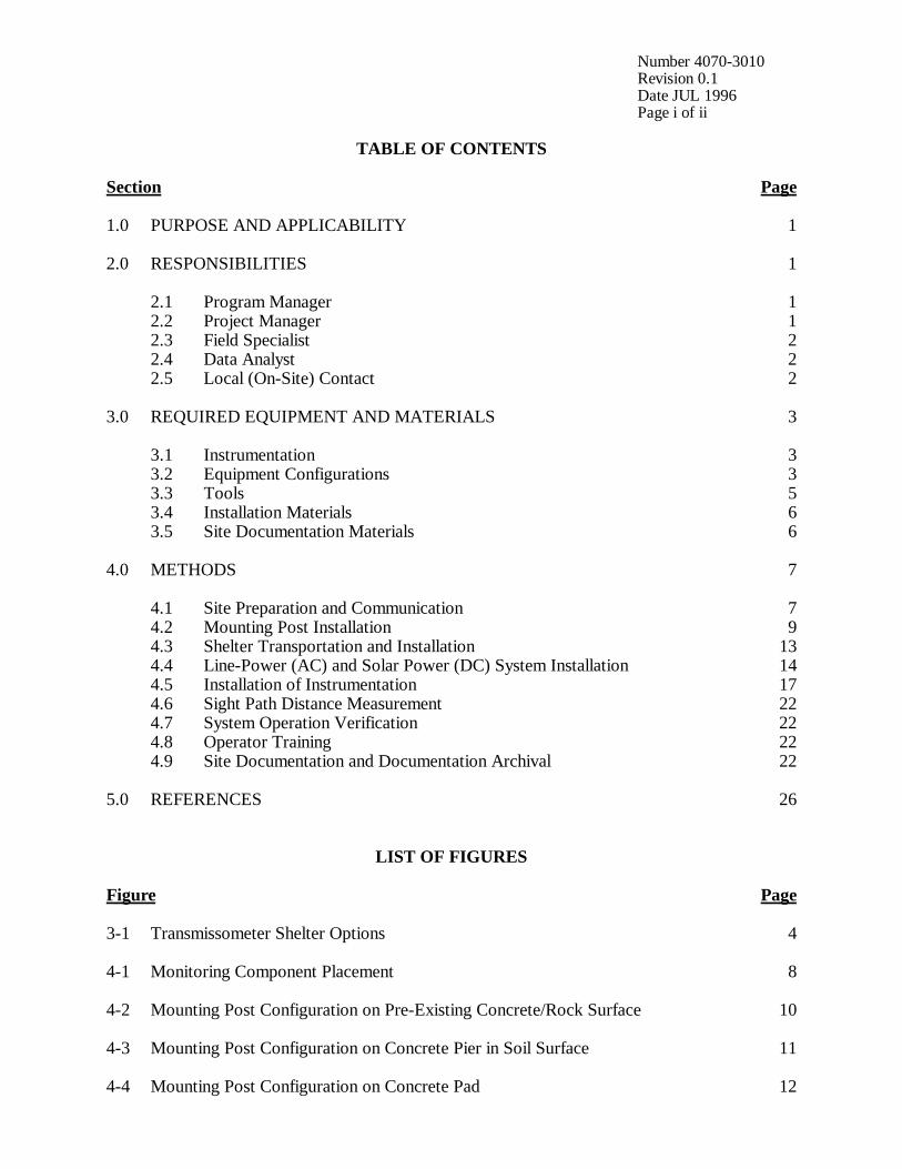
LIST OF FIGURES
Figure Page
3-1 Transmissometer Shelter Options 4
4-1 Monitoring Component Placement 8
4-2 Mounting Post Configuration on Pre-Existing Concrete/Rock Surface 10
4-3 Mounting Post Configuration on Concrete Pier in Soil Surface 11
4-4 Mounting Post Configuration on Concrete Pad 12
Number 4070-3010Revision 0.1Date JUL 1996Page ii of ii
LIST OF FIGURES (CONTINUED)
Figure Page
4-5 Receiver Station Line Power (AC) Configuration Diagram 15
4-6 Transmitter Station Line Power (AC) Configuration Diagram 16
4-7 Receiver Station Solar Power (DC) Configuration Diagram 18
4-8 Transmitter Station Solar Power (DC) Configuration Diagram 19
4-9 Solar Panel Array Installation Configurations 20
4-10 Example Transmissometer Site Description Sheet 24
4-11 Example Site Map and Site Specification Sheet 25

Number 4070-3010Revision 0.1Date JUL 1996Page 1 of 26
1.0 PURPOSE AND APPLICABILITY
This technical instruction (TI) describes the procedures for installation and sitedocumentation of Optec LPV-2 transmissometer stations operated according to IMPROVEProtocol. The purpose of this TI is to assure quality data capture and minimize data loss by:
• Installing the instrumentation, shelters, and support components in a standard configuration to assure ease in data collection, troubleshooting, and servicing.
• Performing thorough on-site specification measurements.
• Documenting site specification measurements and other site-related information.
This TI is referenced from Standard Operating Procedure (SOP) 4070, Installation and SiteDocumentation for Optical Monitoring Equipment. The following SOPs and TIs are referencedin this document:
• TI 4050-3010 Site Selection for Optec LPV-2 Transmissometer Systems
• TI 4110-3350 Transmissometer Monitoring System Diagrams and ComponentDescriptions
• TI 4110-3375 Replacing and Shipping Transmissometer Components
• TI 4115-3000 Annual Site Visit Procedures for Optec LPV-2 TransmissometerSystems (IMPROVE Protocol)
• TI 4200-2100 Calibration of Optec LPV-2 Transmissometers (IMPROVEProtocol)
• SOP 4710 Transmissometer Field Audit Procedures
2.0 RESPONSIBILITIES
2.1 PROGRAM MANAGER
The program manager shall review site preparation, installation requirements, and theinstallation schedule with the project manager.
2.2 PROJECT MANAGER
The project manager shall:
• Review the site preparation, installation requirements, and the installation schedule withthe program manager and/or the project-specific Contracting Officer's TechnicalRepresentative (COTR) as required.
• Review final site configuration plans presented by the field specialist.
• Schedule the system installation.

Number 4070-3010Revision 0.1Date JUL 1996Page 2 of 26
2.3 FIELD SPECIALIST
The field specialist shall:
• Review final site preparation and installation plans with the project manager.
• Inform the site-specific local contact of the installation schedule.
• Review the determined site preparation and installation requirements with the localcontact, as required.
• Maintain communications with the local contact during site preparation. Verify that allrequired site preparation is completed prior to installation.
• Verify that all required clearances and permissions relating to the specific site, systeminstallation, and regular servicing have been obtained prior to the installation.
• Schedule and arrange for any on-site assistance needed during the installation.
• Install the transmissometer system according to this TI.
• Complete all site documentation according to this TI.
• Perform all applicable tasks for annual site visits according to TI 4115-3000, Annual SiteProcedures for Optec LPV-2 Transmissometer Systems (IMPROVE Protocol).
• Perform an installation field audit according to SOP 4710, Transmissometer Field AuditProcedures.
• Schedule an operator training session for all identified operators and conduct the trainingaccording to the procedures described in TI 4115-3000.
• Provide completed site documentation to the data analyst.
2.4 DATA ANALYST
The data analyst shall:
• Verify transmission of data from the system upon completion of the installation.
• Enter all site documentation into the Quality Assurance Database.
• File all hard copy site documentation provided by the field specialist.
2.5 LOCAL (ON-SITE) CONTACT
The local contact shall:
• Review site preparation and installation requirements with the field specialist.

Number 4070-3010Revision 0.1Date JUL 1996Page 3 of 26
• Identify and contact local landowners, land managers, primary contacts, and siteoperators regarding site installation and routine maintenance requirements.
• Perform or ensure completion of any site preparation required prior to the installation.
• Assist in obtaining any site-, installation-, and regular servicing-related clearances andpermits.
• Provide on-site equipment and tools required during the installation.
• As required, provide assistance with the installation.
• Schedule the operator training session with pertinent routine servicing personnel and thefield specialist.
3.0 REQUIRED EQUIPMENT AND MATERIALS
Equipment and materials required to install a transmissometer system includeinstrumentation, equipment for varying site configurations, tools, informational materials, anddocumentation materials. Equipment and materials are detailed in the following subsections.
3.1 INSTRUMENTATION
• Installation transmissometer with calibrated lamps
• Audit transmissometer with calibrated lamps
• Programmed data collection platform (DCP) with antenna, antenna cable, and solarpanel charging system (if solar-powered site) or AC-trickle charger (if AC-powered site)
• AT/RH sensor with housing and cable
• Strip chart recorder and supplies
• Electronic distance meter (EDM) with mirror assembly and tripods
Refer to TI 4115-3000, Annual Site Visit Procedures for Optec LPV-2 TransmissometerSystems (IMPROVE Protocol) for additional required instrumentation.
3.2 EQUIPMENT CONFIGURATIONS
This list will vary depending on individual sites:
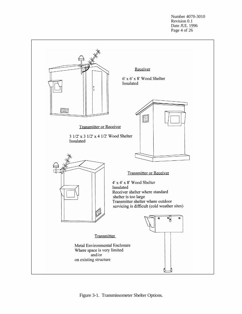
• Receiver and transmitter shelters (assembled or disassembled, dependent on siteinstallation constraints). Refer to Figure 3-1 for standard transmissometer shelters.
• Receiver and transmitter mounting posts and alti-azimuth bases.
• Window/hood assemblies.
• Terminal strip board.
Number 4070-3010Revision 0.1Date JUL 1996Page 4 of 26
Figure 3-1. Transmissometer Shelter Options.
Number 4070-3010Revision 0.1Date JUL 1996Page 5 of 26
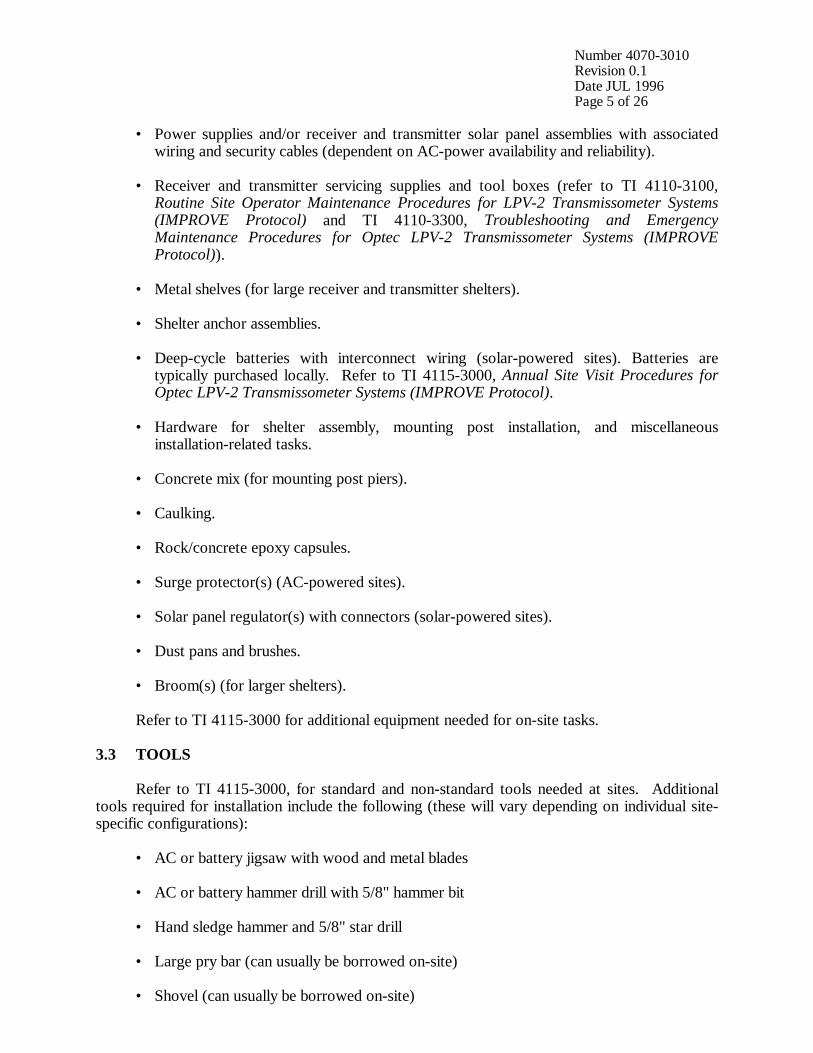
• Power supplies and/or receiver and transmitter solar panel assemblies with associatedwiring and security cables (dependent on AC-power availability and reliability).
• Receiver and transmitter servicing supplies and tool boxes (refer to TI 4110-3100,Routine Site Operator Maintenance Procedures for LPV-2 Transmissometer Systems(IMPROVE Protocol) and TI 4110-3300, Troubleshooting and EmergencyMaintenance Procedures for Optec LPV-2 Transmissometer Systems (IMPROVEProtocol)).
• Metal shelves (for large receiver and transmitter shelters).
• Shelter anchor assemblies.
• Deep-cycle batteries with interconnect wiring (solar-powered sites). Batteries aretypically purchased locally. Refer to TI 4115-3000, Annual Site Visit Procedures forOptec LPV-2 Transmissometer Systems (IMPROVE Protocol).
• Hardware for shelter assembly, mounting post installation, and miscellaneousinstallation-related tasks.
• Concrete mix (for mounting post piers).
• Caulking.
• Rock/concrete epoxy capsules.
• Surge protector(s) (AC-powered sites).
• Solar panel regulator(s) with connectors (solar-powered sites).
• Dust pans and brushes.
• Broom(s) (for larger shelters).
Refer to TI 4115-3000 for additional equipment needed for on-site tasks.
3.3 TOOLS
Refer to TI 4115-3000, for standard and non-standard tools needed at sites. Additionaltools required for installation include the following (these will vary depending on individual site-specific configurations):
• AC or battery jigsaw with wood and metal blades
• AC or battery hammer drill with 5/8" hammer bit
• Hand sledge hammer and 5/8" star drill
• Large pry bar (can usually be borrowed on-site)
• Shovel (can usually be borrowed on-site)

Number 4070-3010Revision 0.1Date JUL 1996Page 6 of 26
• Wheelbarrow (can usually be borrowed on-site)
• Single-wheel field transport cart
• Caulking gun
• Extension cords
• Staple gun with staples
• Wood saw
3.4 INSTALLATION MATERIALS
Refer to TI 4115-3000, Annual Site Visit Procedures for Optec LPV-2 TransmissometerSystems (IMPROVE Protocol) for standard materials needed when at a site. Note that calibrationmemos for the installation and audit transmissometers will need to be revised when the sight pathlength has been measured with the electronic distance meter (EDM). The following additionalmaterials should also be taken when installing a site:
• Information documented during the site selection process. Refer to TI 4050-3010, SiteSelection for Optec LPV-2 Transmissometer Systems.
• Manuals, technical notes, instructions, and other applicable information for thepreviously listed instrumentation and equipment (Sections 3.1 and 3.2).
• Site Operator's Manual for Transmissometer Monitoring Systems (3 copies).
• TI 4110-3350, Transmissometer Monitoring System Diagrams and ComponentDescriptions.
3.5 SITE DOCUMENTATION MATERIALS
The following materials are generally required to complete the site documentation process:
• TI 4115-3000, Annual Site Visit Procedures for Optec LPV-2 Transmissometer Systems(IMPROVE Protocol)
• Transmissometer Network Servicing Site Visit Trip Report and Data Sheet
• On-site documentation acquired by the field specialist during installation
• Topographic maps of the area
• Ruler and protractor
• Photographs of the sites, shelters, sight path, equipment configurations, etc.

Number 4070-3010Revision 0.1Date JUL 1996Page 7 of 26
4.0 METHODS
Refer to Figure 3-1, Transmissometer Shelter Options, and Figure 4-1, MonitoringComponent Placement, for general diagrams of standard transmissometer shelters and systemcomponent placement and configuration.
Refer to TI 4110-3350, Transmissometer Monitoring System Diagrams and ComponentDescriptions, for specific diagrams and descriptions of individual system components.
This section describes site installation and documentation procedures and includes nine (9)major subsections:
4.1 Site Preparation and Communication4.2 Mounting Post Installation4.3 Shelter Transportation and Installation4.4 Line-Power (AC) and Solar Power (DC) System Installation4.5 Installation of Instrumentation4.6 Sight Path Distance Measurement4.7 System Operation Verification4.8 Operator Training4.9 Site Documentation and Documentation Archival
4.1 SITE PREPARATION AND COMMUNICATION
Prior to any installation visit:
• Review the determined site preparation and installation requirements with the localcontact.
• Schedule all site preparation activities.
• Maintain communications with the local contact during site preparation. Verify that allrequired site preparation is completed prior to the installation.
• Document the primary site operator(s) and backup operator(s).
• Obtain permission from private or public landowners to access the monitoring locationfor installation and training.
• Schedule the site installation visit and operator training session. (Typically aninstallation will require approximately 3-4 on-site work days. Training should bescheduled in the latter part of the week when the system is fully installed andoperational).
• Arrange for any necessary installation assistance, as well as tools and/or equipment (e.g.,shovels, wheelbarrow, water containers).
Once on-site:
• Inspect any site preparation that has been done.

Number 4070-3010Revision 0.1Date JUL 1996Page 8 of 26
Figure 4-1. Monitoring Component Placement.
Number 4070-3010Revision 0.1Date JUL 1996Page 9 of 26
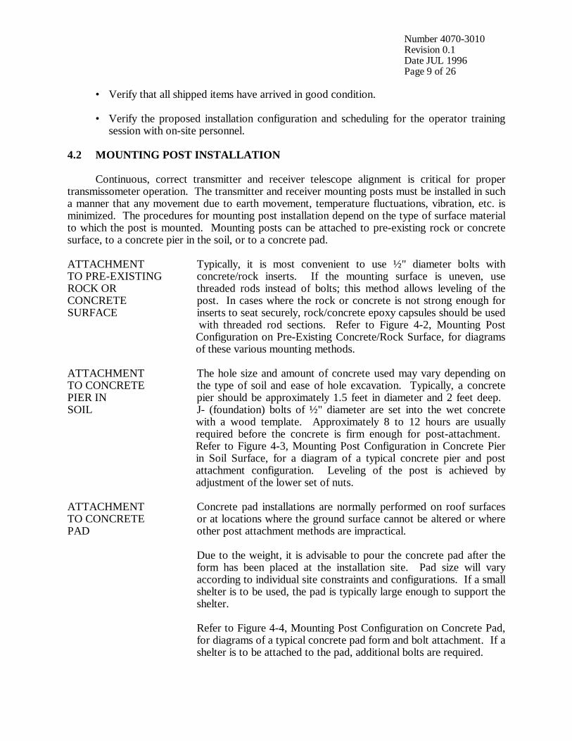
• Verify that all shipped items have arrived in good condition.
• Verify the proposed installation configuration and scheduling for the operator trainingsession with on-site personnel.
4.2 MOUNTING POST INSTALLATION
Continuous, correct transmitter and receiver telescope alignment is critical for propertransmissometer operation. The transmitter and receiver mounting posts must be installed in sucha manner that any movement due to earth movement, temperature fluctuations, vibration, etc. isminimized. The procedures for mounting post installation depend on the type of surface materialto which the post is mounted. Mounting posts can be attached to pre-existing rock or concretesurface, to a concrete pier in the soil, or to a concrete pad.
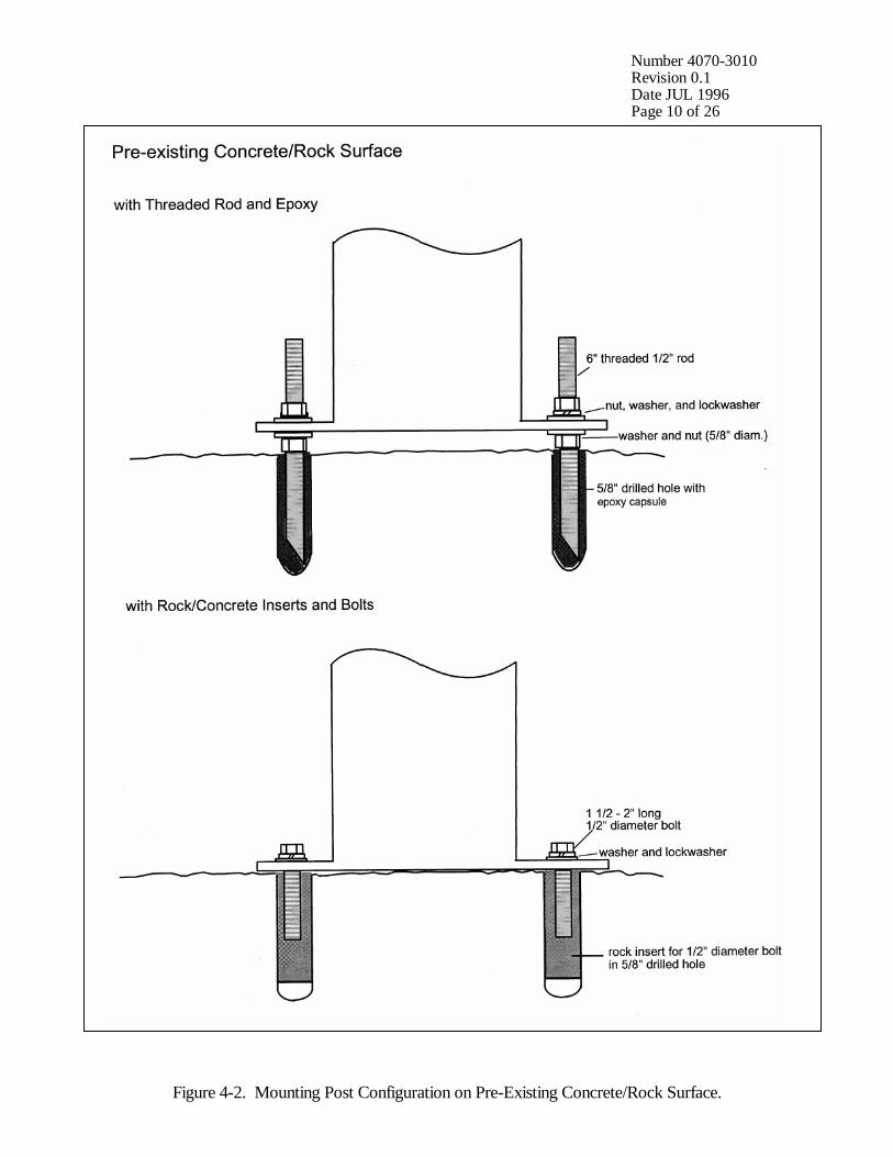
ATTACHMENT Typically, it is most convenient to use ½" diameter bolts withTO PRE-EXISTING concrete/rock inserts. If the mounting surface is uneven, useROCK OR threaded rods instead of bolts; this method allows leveling of theCONCRETE post. In cases where the rock or concrete is not strong enough forSURFACE inserts to seat securely, rock/concrete epoxy capsules should be used with threaded rod sections. Refer to Figure 4-2, Mounting Post Configuration on Pre-Existing Concrete/Rock Surface, for diagrams of these various mounting methods.
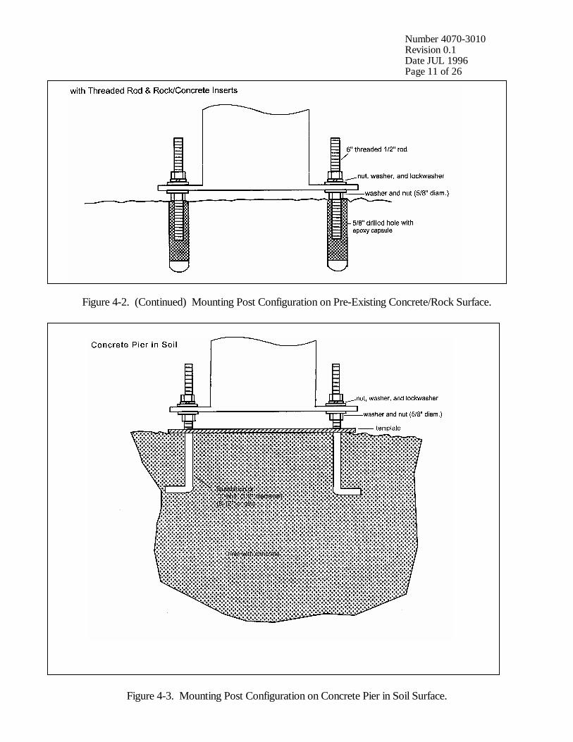
ATTACHMENT The hole size and amount of concrete used may vary depending onTO CONCRETE the type of soil and ease of hole excavation. Typically, a concretePIER IN pier should be approximately 1.5 feet in diameter and 2 feet deep. SOIL J- (foundation) bolts of ½" diameter are set into the wet concrete with a wood template. Approximately 8 to 12 hours are usually required before the concrete is firm enough for post-attachment. Refer to Figure 4-3, Mounting Post Configuration in Concrete Pier in Soil Surface, for a diagram of a typical concrete pier and post attachment configuration. Leveling of the post is achieved by adjustment of the lower set of nuts.
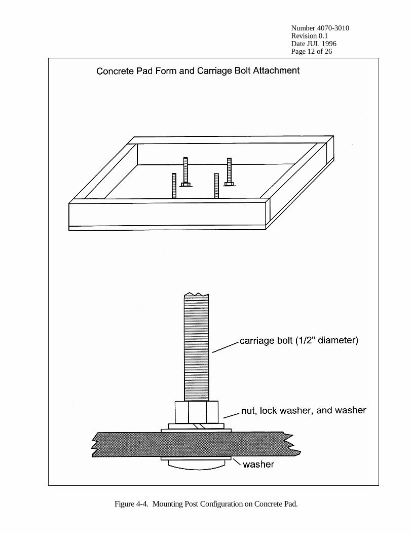
ATTACHMENT Concrete pad installations are normally performed on roof surfacesTO CONCRETE or at locations where the ground surface cannot be altered or wherePAD other post attachment methods are impractical.
Due to the weight, it is advisable to pour the concrete pad after theform has been placed at the installation site. Pad size will varyaccording to individual site constraints and configurations. If a smallshelter is to be used, the pad is typically large enough to support theshelter.
Refer to Figure 4-4, Mounting Post Configuration on Concrete Pad,for diagrams of a typical concrete pad form and bolt attachment. If ashelter is to be attached to the pad, additional bolts are required.
Number 4070-3010Revision 0.1Date JUL 1996Page 10 of 26
Figure 4-2. Mounting Post Configuration on Pre-Existing Concrete/Rock Surface.
Number 4070-3010Revision 0.1Date JUL 1996Page 11 of 26
Figure 4-2. (Continued) Mounting Post Configuration on Pre-Existing Concrete/Rock Surface.
Figure 4-3. Mounting Post Configuration on Concrete Pier in Soil Surface.
Number 4070-3010Revision 0.1Date JUL 1996Page 12 of 26
Figure 4-4. Mounting Post Configuration on Concrete Pad.
Number 4070-3010Revision 0.1Date JUL 1996Page 13 of 26
4.3 SHELTER TRANSPORTATION AND INSTALLATION
SHELTER The method(s) of long-distance and on-site transportation ofTRANSPORTATION transmissometer shelters depend on the following factors:
• Type(s) of shelter(s)
• Disassembled or assembled shelter(s)
• Distances
• Shipping (trucking) company limitations
• Site accessibility
Large shelters are usually transported by trailers or, if disassembled,can also be shipped with trucking companies. Small shelters can betransported by truck, trailer, or be shipped.
On-site transportation of the shelters to the installation locations isprimarily dependent on site accessibility. If vehicle access to the siteis not possible, the shelters or disassembled sections can betransported by carrying, handcart, or wheeled trail transport cart. Ifsite access is very difficult, use of a helicopter should be considered.
SHELTER The general procedures for shelter installation are as follows:INSTALLATION
• Verify that preparations for attachment of the instrumentmounting post have been completed.
• Place the shelter (or shelter floor section, if disassembled) onconcrete blocks or piers. Verify that the floor is level and that theshelter correctly oriented with respect to the transmitter sightpath.
• Assemble the shelter (if disassembled) and attach thewindow/hood assembly.
• Install the instrument mounting post. Verify that there is at least½" clearance between the post and the edge of the shelter floorhole to ensure that shelter vibration is not transferred to the postand instrument.
A rubber boot is placed around the post and attached to the floor toprevent dust, insects, snow, rodents, etc. from entering the shelter. Adjust post height for correct instrument/window alignment and fillthe post with sand to minimize post movement due to thermalcontraction/expansion.
Number 4070-3010Revision 0.1Date JUL 1996Page 14 of 26
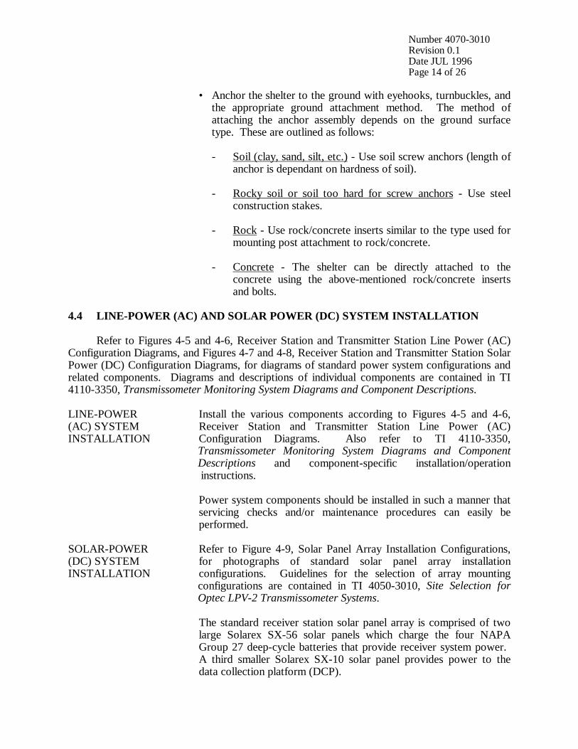
• Anchor the shelter to the ground with eyehooks, turnbuckles, andthe appropriate ground attachment method. The method ofattaching the anchor assembly depends on the ground surfacetype. These are outlined as follows:
- Soil (clay, sand, silt, etc.) - Use soil screw anchors (length ofanchor is dependant on hardness of soil).
- Rocky soil or soil too hard for screw anchors - Use steelconstruction stakes.
- Rock - Use rock/concrete inserts similar to the type used formounting post attachment to rock/concrete.
- Concrete - The shelter can be directly attached to theconcrete using the above-mentioned rock/concrete insertsand bolts.
4.4 LINE-POWER (AC) AND SOLAR POWER (DC) SYSTEM INSTALLATION
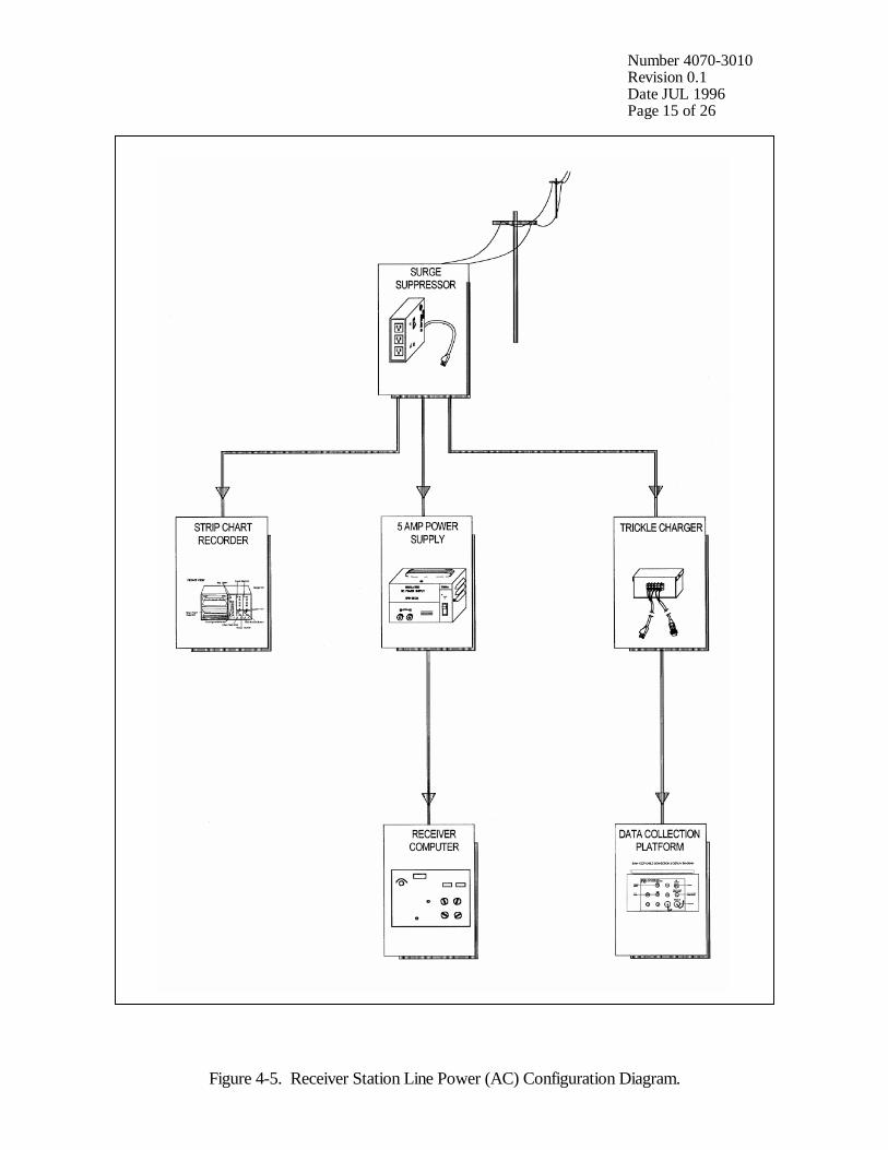
Refer to Figures 4-5 and 4-6, Receiver Station and Transmitter Station Line Power (AC)Configuration Diagrams, and Figures 4-7 and 4-8, Receiver Station and Transmitter Station SolarPower (DC) Configuration Diagrams, for diagrams of standard power system configurations andrelated components. Diagrams and descriptions of individual components are contained in TI4110-3350, Transmissometer Monitoring System Diagrams and Component Descriptions.
LINE-POWER Install the various components according to Figures 4-5 and 4-6,(AC) SYSTEM Receiver Station and Transmitter Station Line Power (AC)INSTALLATION Configuration Diagrams. Also refer to TI 4110-3350, Transmissometer Monitoring System Diagrams and Component Descriptions and component-specific installation/operation instructions.
Power system components should be installed in such a manner thatservicing checks and/or maintenance procedures can easily beperformed.
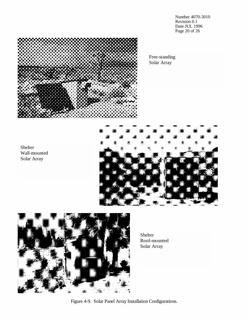
SOLAR-POWER Refer to Figure 4-9, Solar Panel Array Installation Configurations,(DC) SYSTEM for photographs of standard solar panel array installationINSTALLATION configurations. Guidelines for the selection of array mounting configurations are contained in TI 4050-3010, Site Selection for Optec LPV-2 Transmissometer Systems.
The standard receiver station solar panel array is comprised of twolarge Solarex SX-56 solar panels which charge the four NAPAGroup 27 deep-cycle batteries that provide receiver system power. A third smaller Solarex SX-10 solar panel provides power to thedata collection platform (DCP).
Number 4070-3010Revision 0.1Date JUL 1996Page 15 of 26
Figure 4-5. Receiver Station Line Power (AC) Configuration Diagram.

Number 4070-3010Revision 0.1Date JUL 1996Page 16 of 26
Figure 4-6. Transmitter Station Line Power (AC) Configuration Diagram.
Number 4070-3010Revision 0.1Date JUL 1996Page 17 of 26
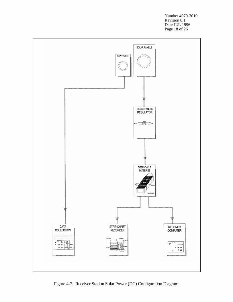
The standard transmitter station solar panel array is comprised of threelarge Solarex SX-56 solar panels which charge the four NAPAGroup 27 deep-cycle batteries that provide transmitter systempower.
Install the various components according to Figures 4-7 and 4-8,Receiver Station and Transmitter Station Solar Power (DC)Configuration Diagrams. Also refer to TI 4110-3350,Transmissometer Monitoring System Diagrams and ComponentDescriptions and component-specific installation/operationinstructions.
A security cable should be run through the solar panel frames andsecured inside the shelter to deter theft of the panels.
Install the four deep-cycle batteries and interconnect wiringaccording to TI 4110-3350.
4.5 INSTALLATION OF INSTRUMENTATION
Refer to TI 4110-3350 for depictions of the various instruments and related equipment andstandard installation configurations. Installation procedures for transmissometer components,data collection platform (DCP), strip chart recorder, and air temperature/relative humidity(AT/RH) sensor are described in TI 4110-3375, Replacing and Shipping TransmissometerComponents.
TRANSMITTER Attach the transmitter and receiver alti-azimuth bases to theAND RECEIVER respective mounting posts. Verify that there is adequate horizontalALTI-AZIMUTH adjustment tension when the transmitter and receiver telescopes areBASE properly aligned. Non-level sight paths may require placingINSTALLATION washers underneath the front or back portions of the bases to ensure proper vertical alignment adjustment.
TERMINAL STRIP Attach the terminal strip to the shelter wall close to where theINSTALLATION receiver computer, strip chart recorder, and data collection platform(RECEIVER (DCP) will be located. Ensure that the terminal strip is readilySHELTER) accessible for servicing checks.
AT/RH SENSOR The AT/RH sensor should be mounted close to the roofline of theINSTALLATION shelter and be far enough from the roof (or any other surface) to(RECEIVER provide representative ambient AT/RH measurements. The AT/RHSHELTER) cable is routed from the sensor into the shelter and connected to the DCP. If possible, install the sensor near the DCP antenna in order that both cables can be routed into the shelter together.
Refer to TI 4110-3375, Replacing and Shipping TransmissometerComponents.
Number 4070-3010Revision 0.1Date JUL 1996Page 18 of 26
Figure 4-7. Receiver Station Solar Power (DC) Configuration Diagram.

Number 4070-3010Revision 0.1Date JUL 1996Page 19 of 26
Figure 4-8. Transmitter Station Solar Power (DC) Configuration Diagram.
Number 4070-3010Revision 0.1Date JUL 1996Page 20 of 26
Figure 4-9. Solar Panel Array Installation Configurations.
Free-standingSolar Array
ShelterWall-mountedSolar Array
ShelterRoof-mountedSolar Array
Number 4070-3010Revision 0.1Date JUL 1996Page 21 of 26
DCP AND Mount the DCP antenna near the roofline of the shelter. If possible,ANTENNA the antenna should be near the AT/RH sensor in order that bothINSTALLATION cables can be routed into the shelter together. Antenna installation(RECEIVER and orientation specifications and procedures are outlined in theSHELTER) Handar DCP Operating and Servicing Manual for each model of DCP (Handar, 1983, 1986, and 1988). Install the DCP according to the procedures described in Section 4.4, Line Power (AC) and Solar Power (DC) System Installation, and TI 4110-3375, Replacing and Shipping Transmissometer Components.
TRANSMISSOMETER Install the transmitter and receiver unit components according toINSTALLATION the procedures described in TI 4110-3375.
STRIP CHART Install the strip chart recorder according to the procedures describedRECORDER in TI 4110-3375.INSTALLATION(RECEIVERSHELTER)
GENERAL General guidelines during the placement and installation ofINSTALLATION instrumentation, related equipment, and supplies are as follows:GUIDELINES
• Place items in an orderly, space-efficient manner.
• Group related items/instrumentation together.
• Ensure that all instrument displays/indicators are easily and clearlyvisible.
• Ensure that all switches, dials, etc., are labeled and clearly visible,and easily accessible.
• Ensure that all connectors/connections are labeled and easilyaccessible.
• In larger shelters, install a shelf for storage of miscellaneous items.
• Upon installation, verify correct operation of each systemcomponent. Operation verification for the entire system isperformed after measurement of the sight path distance.
• Secure excess and/or loose wiring with wire ties.
• Caulk any shelter holes or cracks around the window/hoodassembly, etc. to prevent dust, precipitation, insects, etc. fromentering the shelter.
Number 4070-3010Revision 0.1Date JUL 1996Page 22 of 26
4.6 SIGHT PATH DISTANCE MEASUREMENT
Measurement of the sight path distance is made with the electronic distance meter (EDM). Refer to the EDM operating manual (Hewlett Packard) for operational procedures.
The distance measurement is made from the front of the receiver telescope tube to the frontof the transmitter telescope tube. The measurement should be repeated at least three times.
Once the distance measurement has been made, the distance is communicated to the projectmanager in order that the transmissometer calibration numbers can be recalculated using theaccurate distance value.
The recalculated calibration numbers are communicated to the on-site field specialist, andthe correct calibration number is dialed in on the receiver computer.
4.7 SYSTEM OPERATION VERIFICATION
Once the instrument settings and system timing have been set at the transmitter andreceiver, system operation can be verified. Operation verification and documentation isperformed according to the procedures described in TI 4115-3000, Annual Site Visit Proceduresfor Optec LPV-2 Transmissometer Systems (IMPROVE Protocol). Also, all other pertinentoperational- and servicing-related tasks and procedures are performed as described in the afore-mentioned TI 4115-3000.
4.8 OPERATOR TRAINING
Upon completion of the installation and system operation verification, all operators, back-up operators, and any other involved or interested on-site personnel are trained according to theprocedures outlined in TI 4115-3000. The Site Operator's Manual for TransmissometerMonitoring Systems is reviewed and a copy left at both transmitter and receiver sites. The thirdcopy is to be kept at the office of on-site personnel.
4.9 SITE DOCUMENTATION AND DOCUMENTATION ARCHIVAL
ON-SITE On-site documentation is performed by the field specialist asDOCUMENTATION follows:
• Completion of the Transmissometer Network Servicing Site VisitTrip Report and Data Sheet
• Photographic documentation of the following:
- Shelters, various views
- Windows and hoods
- Antenna with mount
- AT/RH sensor with mount

Number 4070-3010Revision 0.1Date JUL 1996Page 23 of 26
- Shelter supports and mounting post attachments
- Sight path, receiver to transmitter, and transmitter toreceiver, at various zoom settings (35 mm, 50 mm, 135 mm)
- Shelter interior configurations/layouts
- Computer and strip chart
- Terminal strip board
- Receiver and transmitter telescopes on mounts
- DCP and associated wiring
- Batteries and solar panel regulator (solar-powered sites)
- Power supply and surge protector (line-powered sites)
- Solar panels (solar-powered sites)
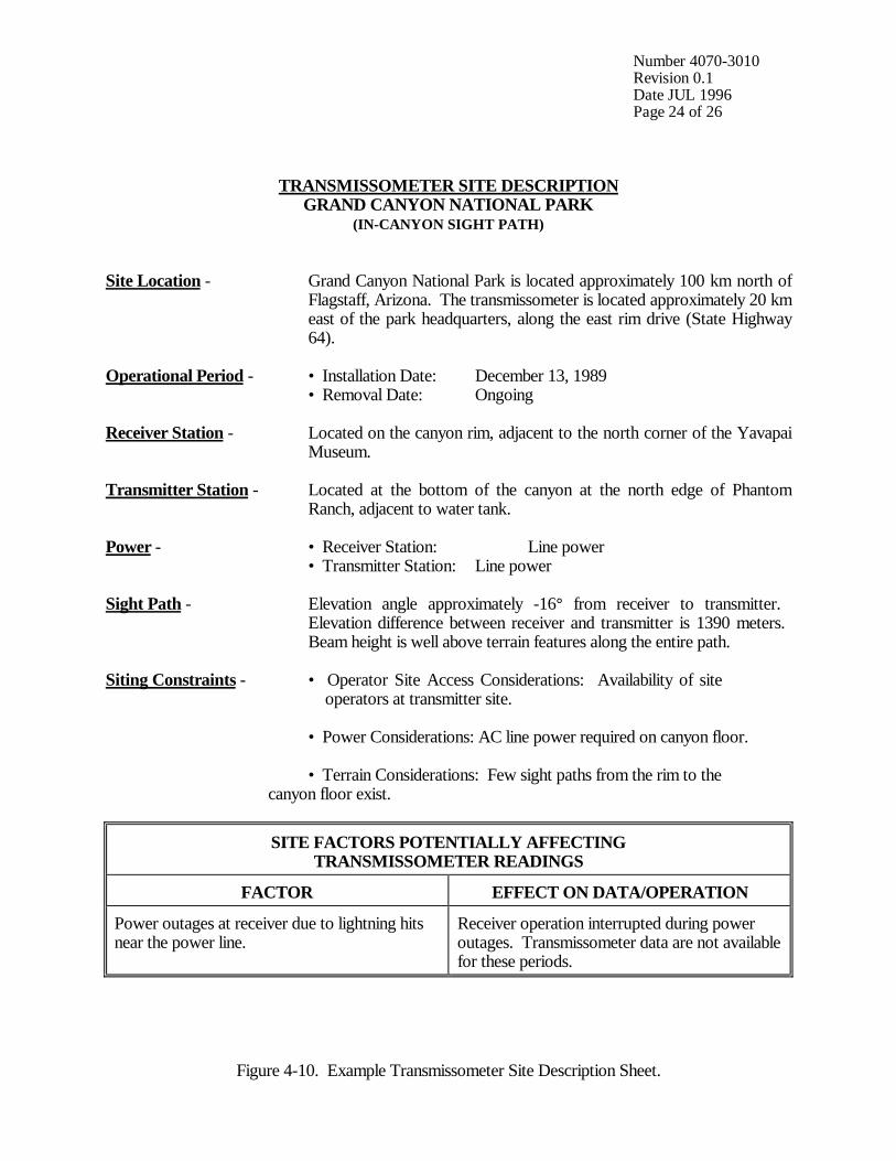
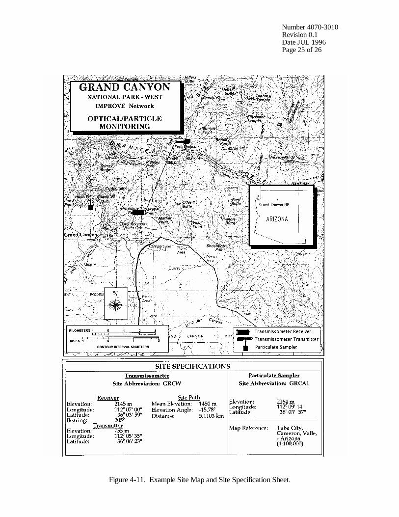
• Documentation of miscellaneous information necessary tocomplete the Transmissometer Site Description Sheet and theSite Map and Site Specifications Sheet. Refer to Figure 4-10, Example Transmissometer Site Description Sheet andFigure 4-11, Example Site Map and Site SpecificationsSheet.
POST-INSTALLATION Within one week after return from the installation trip, the followingTRIP SITE documentation is completed:DOCUMENTATIONAND ARCHIVAL • Completion of the Transmissometer Site Description and the Site
Map and Site Specifications Sheets
• Developing of all film from site photographic documentation
Upon completion of this documentation, post-visit procedures, asdescribed in TI 4115-3000, Annual Site Visit Procedures for OptecLPV-2 Transmissometer Systems (IMPROVE Protocol), areperformed. Additional procedures, not described in these post-visitprocedures are performed as follows:
• Archival of the Transmissometer Site Description and the SiteMap and Site Specifications Sheets in site-specific operations fileslocated in the ARS data collection center
• Organization and filing of the site photographic documentation bythe data analyst
Number 4070-3010Revision 0.1Date JUL 1996Page 24 of 26
TRANSMISSOMETER SITE DESCRIPTIONGRAND CANYON NATIONAL PARK
(IN-CANYON SIGHT PATH)
Site Location - Grand Canyon National Park is located approximately 100 km north ofFlagstaff, Arizona. The transmissometer is located approximately 20 kmeast of the park headquarters, along the east rim drive (State Highway64).
Operational Period - • Installation Date: December 13, 1989• Removal Date: Ongoing
Receiver Station - Located on the canyon rim, adjacent to the north corner of the YavapaiMuseum.
Transmitter Station - Located at the bottom of the canyon at the north edge of PhantomRanch, adjacent to water tank.
Power - • Receiver Station: Line power• Transmitter Station: Line power
Sight Path - Elevation angle approximately -16° from receiver to transmitter. Elevation difference between receiver and transmitter is 1390 meters. Beam height is well above terrain features along the entire path.
Siting Constraints - • Operator Site Access Considerations: Availability of site operators at transmitter site.
• Power Considerations: AC line power required on canyon floor.
• Terrain Considerations: Few sight paths from the rim to the canyon floor exist.
SITE FACTORS POTENTIALLY AFFECTINGTRANSMISSOMETER READINGS
FACTOR EFFECT ON DATA/OPERATION
Power outages at receiver due to lightning hitsnear the power line.
Receiver operation interrupted during poweroutages. Transmissometer data are not availablefor these periods.
Figure 4-10. Example Transmissometer Site Description Sheet.
Number 4070-3010Revision 0.1Date JUL 1996Page 25 of 26
Figure 4-11. Example Site Map and Site Specification Sheet.

Number 4070-3010Revision 0.1Date JUL 1996Page 26 of 26
5.0 REFERENCES
Handar, Inc., May 1983, Operating and Service Manual for 540A Multiple Access Data Acquisition System, 560A Hydrologic Data Collection System, and 545 Programming Set.
Handar, Inc., September 1986, Operating and Service manual for 540A-1 Multiple Access DataAcquisition System, 560A Data Collection System, 570A Expandable Hydromet DataAcquisition System.
Handar, Inc., March 1988, 570A Data Acquisition System Operating and Service Manual.
Hewlett Packard, The HP 3808A Medium Range Distance Meter.