Embed Size (px)
Citation preview

SwingRiser™
14, 19, 30
D0121
Sold by
Dealer/Installer: __________________________
Phone: ________________________________
Distributor: ______________________________
Phone: ________________________________
Sales: 1-800-321-9947 Fax: 1-888-321-9946www.hysecurity.com Email: [email protected] Support: Call your dealer or distributor6623 South 228th Street, Kent, WA 98032
Installation and Reference Manual
(HRG)
Hydraulic swing gate operator with Smart Touch controller


HySecurity® Gate – Quick Start Instructions
For HRG Swing Gates
These instructions are provided as a quick reference guide to the experienced installer that is already familiar with all safety precautions and the installation of this gate operator. Do not attempt to install from this guide if you are inexperienced with this product.
1. Use four ⅝-inch to ¾-inch anchor bolts to mount the 12-inch square operator base. Provide a 1-inch clearance from the backing post or the wall. It is important that the operator be plum and true. Use shims to level the base.
2. Attach the top of the operator to the backing post or supporting wall, using the bracket provided. The attaching bracket ―sleeves‖ inside the top of the operator post. Note: The backing post/column must accommodate the entire “tip over” load imposed by the gate panel.
3. Mount the controller box within 100 feet of the gate operator post, and preferably within 20 feet. If installing the DC version of the operator, be careful to mount the battery power supply box very near the control enclosure because of the high current demand by the DC motor.
4. Pull four wires, 18 gauge minimum, for the limit switches from each post to the controller box.
5. Remove the lower cover (at 2 foot height) on the post(s) and connect the limit switch wires. The open limit is slightly lower in height than the close limit. Also connect the limit wires to the controller box at the five pole terminal strip marked open limit and close limit.
6. For protection, tape the ends and pull the hydraulic hoses through the 2-inch conduit from each post to the controller box. Connect the hydraulic hoses to the color-coded couplings at the base of each post. Also connect the hoses to the power unit inside the control box, again matching the color coding.
7. Connect the electrical power to the loose wires from the On/Off switch and a grounding wire to the lower left corner of the electrical panel. Be certain the labeled voltage and phase of the operator matches the available supply. Note: For the DC version, refer to the appendix of the Installation and Maintenance manual.
8. Turn on the power switch. The Smart Touch LCD display should show, after a 2-second delay, the characters [uC_0]. This is a setting for the UL user class that must be made before any function will be possible. Press the Select button, then the Next button and change the 0 to be class 1-4 as appropriate for the site. Press the Select button again to lock the setting.
9. Press the Menu button and the display will jump to the close timer setting [Ct_0]. If a close timer function is needed, set in the same manner as above. Press the Menu button again to exit to the Run Mode. The LCD display should now read StoP or CLoS.
10. Test for normal operation of the gate. If the hoses are connected incorrectly, the gate will move the wrong direction. (see step 6). If the gate moves the correct direction, but triggers an Err1 alert, the wiring of the open and closed limit switches are reversed. (see step 5)
11. After normal function has been verified, connect any required accessory device wiring. Note that the various inputs are all one wire only to the main terminal strip while the other wire connects to the Common Buss on the nearby power supply board.
12. To access the User menu in the Smart Touch Controller, simply press the Menu button while there is no active Open or Close input. The display will scroll system values and stop at the [Ct__] close timer setting. There are 12 menu items in the User Menu. To reach the more detailed Installer menu, the system must be in the User Menu first, and then simultaneously press Open and Reset. The display will go to [uC__] which is the first of 34 items in the Installer Menu. Read the instructions before attempting any adjustments!

Installation and Maintenance Manual
HySecurity Hydraulic Swing Gate Operator
Smart Touch Controller Menu Guide for Swing Gates To gain access to the User Menu, press the Menu button when the gate is stopped. The LCD will scroll through key several items, then stop at the close timer setting [Ct ].
User Menu Options Default Description U1 [Ct 0] Close timer setting 0 0 = Close timer off or 1 – 99 seconds U2 [hC 0] Momentary Close 0 0 = momentary, 1= Constant hold PB required U3 [ho 0] Momentary Open 0 0 = momentary, 1= Constant hold PB required U4 [AP 0] AC Power loss function 0 0 – 3 (0 =Type A, 1 = B, 2 = C, 3 = D) U5 [ro 0] Radio control option 0 0 = Open only, 1 = Adds close ability when full open U6 [bF 2] Warn before operate 2 0 =off, 1 = Buzzer alerts 3 seconds before + in motion, 2 =
Buzzer alerts 3 sec before + 2 seconds in motion U7 [FA 0] Forced open Alert and
automatic gate reposition 0 0 = off, 1 sound buzzer (2 pulses/sec) if forced
open for more than four seconds, time out in 30 Sec U8 [dA 0] Drift Closed Alert and
automatic gate reposition 0 0 = off, 1 sound buzzer (2 pulses/sec) if drift closed and
cannot reopen within four seconds. U9 [PE 0] Photo Eye Align Mode 0 0= off, 1 = on (auto off when close limit triggered) U10 [CL 0] Clock set (24 hour type) 0 0= display, 1= set mins, 2= set hours, 3= day, 4= month U11 [Ld 5] LCD Contrast set 5 1 - 9 = Adjusts contrast of the display U12 [dS 0] Data Log (New Gen only) 0 0 = Std. 1 = Extended (reset to 0 in 24 hr) (V4.xx software)
To access Installer Menu, press the Open & Reset buttons together while in the User Menu.
Installer Menu Options Default Description I1 [uC 0] Set UL Usage Class 0 0 = Gate disabled, Set Class 1 through 4 use I2 [bu 0] Choose Buzzer 0 0 = Buzzer not set, 1 = Freq 1, 2 = Freq. 2 I3 [Fd 0] Load Factory Defaults 0 0 = User settings, 1 = Load defaults (resets full menu) I4 [dg 0] Set Master/Slave type 0 0 = Solo operator, 1 = Slave unit, 2 = Master unit I5 [Ch 0] Set AC Charger or Solar 0 0 = DC + AC charger, 1 = DC + Solar charger I6 [Fo 0] Enable Fire Dept. Open 0 0 = input disabled, 1 = enabled I7 [oC 0] Enable Emergency close 0 0 = input disabled, 1 = enabled I8 [SE 2] Inherent Sensor sens. 3 1 = Maximum sensitivity, 9 = Lowest sensitivity I9 [SS 0] Inherent Sensor function 0 1 = stop only (note, functions in usage class 4 only) I10 [LC 0] Leaf delay Close 0 0 = none (1-7) ½ second steps (Master/Slave only) I11 [Lo 0] Leaf delay Open 0 0 = none (1-7) ½ second steps (Master/Slave only) I12 [rt 0] Maximum run timer 0 0 = 60 Seconds max run, 1 = 300 Seconds max run I13 [EC 0] PEC reverse to open 0 0 = Close eye stops only, 1 = 2 sec reverse to open I14 [EO 0] PEO reverse to close 0 0 = Open eye stops only, 1 = 2 sec reverse to close I15 [gr 0] Edge reverse to open 0 0 = Edge reverses fully open, 1 = Edge reverses for 2 sec I16 [Sr 1] IES reverse to open 1 0 = IES reverses fully open, 1 = IES reverses for 2 sec I17 [PC 0] Set PEO/ PEC – NO/NC 0 0 = Normally Open PE output, 1 = N.C. (Supervised) I18 [gC 0] Set Edge input – NO/NC 0 0 = Normally Open Edge output, 1 = Normally Closed I19 [tC 1] Time clock/ Interlock input 1 0 = select Time Clock, 1 = select Open Interlock I20 [dt 0] Disable Free Exit/Close Tmr 0 0 = disable Free Exit, 1 = disable Close Timer I21 [or 1] OOLD detector function 1 0 = pause closing only, 1 = enable reversing to open I22 [ir 1] IOLD detector function 1 0 = pause closing only, 1 = enable reversing to open I23 [hd 1] SLD Shadow detector funct 1 0 = Hold open only, 1 = Hold closed + Hold open I24 [dL 1] Vehicle detector logic 1 1 = Std, 2 = Close timer counts down even with loops active I25 [r1 0] User relay 1 option 1 0 = disabled, 1 – 24 = see relay output options I26 [r2 0] User relay 2 option 6 0 = disabled, 1 – 24 = see relay output options I27 [r3 0] User relay 3 option 1 0 = disabled, 1 – 24 = see relay output options I28 [tL 0] Gate Open alert 2 0 = 0 sec, 1= 15s, 2= 45s, 3= 75s, 4= 105s, 5= 135s I29 [Lt 0] Loitering alert 3 0 = 0 sec, 1= 15s, 2= 45s, 3= 75s, 4= 105s, 5= 135s I30 [SA 0] System Address 0 0 = no network, 1-99 = network ―drop‖ address I31 [ELd0] Test factory ELD* 0 0=Run, 1=show freq, 2=show call level 0-7, 3=set freq 1-4 I32 [iLd0] Test factory IOLD* 0 0=Run, 1=show freq, 2=show call level 0-7, 3=set freq 1-4 I33 [oLd0] Test factory OOLD* 0 0=Run, 1=show freq, 2=show call level 0-7, 3=set freq 1-4 I34 [SLd0] Test factory SLD* 0 0=Run, 1=show freq, 2=show call level 0-7, 3=set freq 1-4

HySecurity Gate Operators
SWINGRISER
SWING GATE Operators
With Smart Touch Controller
Installation and Maintenance Manual
SwingRiser (HRG 220 ST) SwingRiser Twin (HRG 222 ST)
and UPS (DC Battery Backup)
Models
D0121, Rev. D

Installation and Maintenance Manual
HySecurity Hydraulic Swing Gate Operator
Hydraulic Swing Gate Operator
With Smart Touch Controller
©Copyright 2010 HySecurity Gate Inc. All rights reserved. No part of this manual may be reproduced by any means: photocopier, electronic or mechanical, without the express written permission of HySecurity Gate Inc. Additionally, HySecurity Inc. makes no representations or warranty with respect to this manual. We also reserve the right to make changes in the products described without notice and without any obligation to notify any persons of any such revision or change.

Installation and Maintenance Manual
HySecurity Hydraulic Swing Gate Operator
Table of Contents
Introduction ...................................................................................................................... v
Warranty Registration ..................................................................................................... vi
Available Models and Features ....................................................................................... 1
I. Safe Gate Design
Important Information ..................................................................................................... 3
Install an Automatic Operator Only When: .................................................................. 4
Important Information for Gate System Owners & Users ............................................ 5
I. Installation
Scope and Planning of Installation ................................................................................ 6
Tools Required ............................................................................................................... 8
Technical Drawings .................................................................................................. 9 - 13
Inside the HRG Swing Operator ................................................................................... 14
Preparation and Installation .................................................................................. 15 - 18
Mounting the Gate Panel, Index Arm, and Lock Pin Assembly ................................. 19
Adjustment of Flow Regulating Valve ......................................................................... 21
Manual Operation Hand Pump ..................................................................................... 22
II. Smart Touch Set Up
Basics of Using the Smart Touch Controller .............................................................. 23
Installation Configuration for Smart Touch Controller .............................................. 24
Wiring Control Inputs to the Smart Touch Controller ......................................... 25 - 26
Connecting a Master/Slave Pair ................................................................................... 27
Smart Touch Controller Menu for Hydraulic Swing Gates ........................................ 28
Installer Menu Functions .............................................................................................. 29
User Menu: Description of Functions Available ......................................................... 30
Installer Menu: Description of Functions Available ............................................ 31 - 32
Optional Wiring.............................................................................................................. 33
Options for User Programmable Output Relays ......................................................... 34
Clock Functions ............................................................................................................ 35
III. Entrapment Protection
Entrapment Protection Schematic ............................................................................... 36
UL 325 Standard Requirements: Gate Operator Usage Class ................................... 37
Placement and Use of Secondary Pedestrian Entrapment Sensors......................... 38
Installation and Maintenance Manual
HySecurity Hydraulic Swing Gate Operator
Table of Contents, continued
Installing Gate Reversing Edge (Contact Type) Sensor ............................................ 39
Installing Photoelectric (Non-Contact) Sensor ................................................... 40 - 41
IV. Detectors and Loops
Loop and Detector Installation Guide .................................................................. 42 - 43
Loop Layouts ......................................................................................................... 44 - 45
Vehicle Detector Installation Options .......................................................................... 46
HySecurity Hy-5A Vehicle Detector Installation ......................................................... 47
Standard 11 Pin Box Type Vehicle Detector Installation ........................................... 48
Vehicle Detector & Loop Fault Diagnostics ................................................................ 49
V. Accessories
24 Hr / 7 Day Time Clock Option .................................................................................. 50
Connecting a Radio Receiver ........................................................................................ 50
VI. Troubleshooting and Maintenance
Troubleshooting .................................................................................................... 51 - 53
General Maintenance ............................................................................................ 54 - 61
Operator Post ............................................................................................................. 54
Hydraulic System ....................................................................................................... 58
Electrical Controls ..................................................................................................... 60
Pressure Relief Valve Adjustments and Maintenance Schedule ........................... 61
VII. DC Operators
DC Systems (HRG 220 DC & HRG 222 DC)
Important Notes about DC Powered Gates ................................................................. 63
Wiring & Control Configurations ................................................................................. 64
Battery Connection Diagram ........................................................................................ 65
VIII. Appendix
Wiring Size Schedules ........................................................................................... 66 - 67
Parts Breakout Diagrams ...................................................................................... 68 - 72
Smart Touch Controller Connections. ....................................................................... .73
Limited Warranty ........................................................................................................... 75

Installation and Maintenance Manual
HySecurity Hydraulic Swing Gate Operator
Introduction
Welcome – We would like to take this opportunity to thank you for this
purchase. HySecurity has manufactured the finest hydraulic gate
operators available since the 1970s. Our commitment to quality and
innovation will become evident as you become familiar with the features
and performance of this expertly engineered machine. All HySecurity
operators are equipped with the Smart Touch Controller, a digital
electronic brain that offers unparalleled features.
Please take a few minutes to study the contents of this instruction manual.
The benefits of taking a little extra time to align the gate operator properly
and to verify a fully functional installation will ensure customer satisfaction
and a longer life with minimal maintenance costs.
Installers and owners must be certain to thoroughly review and
understand the Important Information regarding pedestrian
entrapment protection contained within this manual. There are
hazards associated with automatic gates that can be greatly reduced
with proper design, installation use. When an automatic gate is first
made functional, the installer must teach the owners and users how
to operate this system correctly. When the installation is complete,
leave this manual for the owner’s use and reference.
Please do not hesitate to give your HySecurity distributor a call if you
experience any difficulties during the installation. They are experienced
and trained to assist in resolving any problems.

© 2009 D0119 Rev. G
PRODUCT & WARRANTY REGISTRATION
Enter the following information to register your HySecurity product. Please write legibly. Today’s Date:_____________________
NOTE: To extend the operator warranty beyond 1 year, you must return this registration within 60 days of purchase. Refer to the Limited Warranty.
Installer Information
First/Last Name: _________________________________________
Company Name: _________________________________________
Address: _______________________________________________
City: ____________________________ State/Province: __________
Country: _______________________ Postal Code: ____________
Daytime Phone: ___________________ Fax: __________________
E-mail: _________________________________________________
End-user Information
First/Last Name: _________________________________________
Company/Association: ____________________________________
Address: _______________________________________________
City: ____________________________ State/Province: __________
Country: _______________________ Postal Code: ____________
Daytime Phone: ___________________ Fax: __________________
E-mail: _________________________________________________
Product Information
Model name/number: ______________________________________
Serial number: ___________________________________________
Purchase Date: __________________________________________
Purchase Price: __________________________________________
Distributor’s name: _______________________________________
Distributor’s City: ________________________________________
Country: ________________________________________________
Installation Date: _________________________________________
Who is completing this form?
Installer End User Distributor
Maintenance Personnel Other ___________________
Additional Comments
_______________________________________________________
_______________________________________________________
Did you visit the HySecurity website before purchasing your product?
Yes No
How did you hear about HySecurity gate operators? (Check all that apply.)
Advertisement Exhibition Distributor
Business associate Other (please specify): ____________________________________
What factor(s) most influenced your purchase? (Check all that apply.)
Performance Price Power
Reliability Brand Prior Experience
Recommendation Warranty Product Weight
Fax or Mail this completed form to:
HySecurity, Inc Fax: 888-321-9946 6623 South 228
th Street Email: [email protected]
Kent, WA 98032
HySecurity provides product installation, maintenance and troubleshooting training. View opportunities online at the HySecurity website: www.hysecurity.com/support. For Technical Support, call 800-321-9947.
HySecurity does not share this warranty registration information with third parties unless the requested services, transactions, or legal requirements necessitate it.

Installation and Maintenance Manual
1
Available Models and Features
HySecurity manufactures twelve different models of hydraulic swing gate operators to suit the size,
weight and desired speed of the gate panel. All of the operator models are derived from the standard HRG 220, which is the basis of this manual. Take a moment to identify the operator model you have and note there are some changes in the instructions, especially in regards to final adjustments of double swing gates. The following chart shows the differences at a glance: Panel Operator Model Operator Model Operator Model
Single SwingRiser 14 (HRG 220A) SwingRiser 19 (HRG 220) SwingRiser 30 (HRG 220C) Double SwingRiser 14-Twin (HRG 222A) SwingRiser 19-Twin (HRG 222B) SwingRiser 30-Twin (HRG 222C)
24V UPS Models Single SwingRiser 14 UPS (HRG 220ADC) SwingRiser 19 UPS (HRG 220BDC) SwingRiser 30 UPS (HRG 220CDC) Double SwingRiser 14-Twin UPS SwingRiser 19-Twin UPS SwingRiser 30-Twin UPS (HRG 222ADC) (HRG 222BDC) (HRG 222CDC)
Features: Horsepower (all HRG 220 models are 1 HP, all HRG 222 models are 2 HP) Time To Open/Close 14 sec 19 sec 30 sec UL Usage Class 1 – 4 1 – 4 1 – 4 Warranty 5 years 5 years 5 years Soft Stop yes yes yes Soft Start yes yes yes Gate Panel Ratings: Weight Capacity 1000 lbs 1600 lbs 3000 lbs Gate Size Capacity 9 ft. wide 16 ft. wide 16 ft. wide
The SwingRiser (HRG 220) series operator is the only truly industrial grade swing gate operator on the market today. This tough operator is ideally suited to dependable operation of massive iron or steel gates. Its 3000-lb capacity provides plenty of power, and the Lift and Swing feature eliminates normal obstacles such as heavy snowfall and inclined or irregular roadways. The operator’s mechanism is wholly enclosed inside the post and uses no other devices to push or pull on the gate panel. Its unique closing action self actuates a locking pin at the end of the gate for unparalleled security.
Quarter turn rotating arc of 90 or 100 . No actuating arms or back space required.
Low profile power pack and electric panel are designed to be remotely located. This allows for a clean presentation at the side of the drive.
Twelve-inch rise in the opening cycle allows the swing gate to operate easily on slopes or rise over curbs.
Closing action drops a locking pin at end of gate into socket in driveway, allowing far better security.
Operator post is treated with an industrial galvanized flame spray finish to provide excellent corrosion resistance.
Heavy duty components handle gates to 16 feet wide and up to 3000 lbs of any construction.
Rated for continuous duty, up to 200,000 cycles with no maintenance.
All components are designed for easy removal during service.
The hydraulic system features the latest technology, modular manifolds and individually replaceable cartridge valves.
Fully compatible with all standard access control equipment.
Accessories include heaters, vehicle detectors, photo eyes, gate edges
Hand pump manual operation is standard
equipment.

Installation and Maintenance Manual
2
Available Models and Features The Smart Touch Controller (Standard) This is the brain of the all HySecurity’s automatic operators. Truly high technology, but is also very rugged to reliably serve in the harsh environments that exist in the real world. The Smart Touch Controller is also very smart and can quickly be configured by an installer or user to adapt to almost any functional requirement of a specific site. All system settings are performed with the use of just five programming buttons and an LCD display. The Smart Touch Controller has no switches of any type to set. An RS232 port is for external communication is standard. The system also has a real time clock and an EEPROM to record system events. The log of events can be downloaded from the RS232 port with a PC computer and serial cable. Our optional vehicle detector modules set a new industry standard by communicating a host of valuable performance data to the microprocessor in the Smart Touch Controller, providing user-friendly diagnostics.
DC 24-Volt UPS Operators (Optional Version) These gate operators function from 24 Volts DC all of the time to achieve a true UPS system. Our Uninterruptible Power Supply is the most certain way to know that your gate will work when the AC power fails. This system features fully sealed maintenance free batteries in a separate insulated and ventilated enclosure.
Pedestrian Entrapment Protection Read and understand all the Important Information, the Entrapment Protection Schematic and the UL requirements before beginning the installation. Be absolutely certain that the required type and quantity of Entrapment Protection devices have been supplied and that you understand how to install them correctly. Contact a distributor or the factory if there are any questions about Entrapment Protection.
Basic Access Control Radio Transmitter
Long Distance Control Pushbutton Control Station Programmable Time Clock
Card Reader
Basic Access Control Radio Transmitter
Long Distance Control Pushbutton Control Station Programmable Time Clock
Card Reader
Basic Access Control Radio Transmitter
Long Distance Control Pushbutton Control Station Programmable Time Clock
Card Reader
Basic Access Control Radio Transmitter
Long Distance Control
Advanced Access Control Access Control Interface
Card Reader Keypad
Telephone Entry Input/Output
Computer Interface RS232/485
Advanced Access Control Access Control Interface
Card Reader Keypad
Telephone Entry Input/Output
Computer Interface RS232/485
Advanced Access Control
Information Signs Labels
Warnings
Information Signs Labels
Warnings
Information Signs Labels
Warnings
Information Signs Labels
Warnings
Security Key Locks
Closed Circuit Television
Gate Position Indicator Interlock/Sally Port
Gate Status Indicator
Security Key Locks
Closed Circuit Television
Obstruction Sensing Devices Inherent Sensing Device
Gate Edges Photo Eyes
Vehicle Detectors
Obstruction Sensing Devices Inherent Sensing Device
Gate Edges Photo Eyes
Vehicle Detectors

Installation and Maintenance Manual
3
Safe Gate Design
READ THIS FIRST!
Important Information – Review Before Installation Automatic gate operators provide convenience and security to users. However, because these machines can produce high levels of force it is important that all gate operator system designers, installers and end users be aware of the potential hazards associated with improperly designed, installed or maintained systems. Keep in mind that the gate operator is only one component of the total gate operating system. It is the joint responsibility of the specifier, designer, purchaser, installer and end user to verify that the total system is appropriately configured for its intended use. All parties should be informed that entrapment in a moving gate could cause serious injury or death.
Common
Industry
Symbols
Important Instructions for Gate System Designers & Installers: WARNING: To reduce the risk of serious injury or death, read and follow all instructions in the gate operator handbook and on the warning labels.
Install an Automatic Gate Operator Only When:
The entry is configured for vehicular use only. Pedestrians must be directed to a separate walk-through entrance.
The Warning signs that have been supplied with this operator must be installed, in manner clearly visible, in the area of both sides of the gate.
All exposed pinch points, are guarded. To reduce the risk of entrapment, the gate must also be installed so that enough clearance is provided between the gate and adjacent structures both when opening and closing.
The controls that operate the gate have been mounted far enough away from the moving gate such that users cannot touch the gate while operating the controls. All easily accessible controls must have a security feature to prevent unauthorized use.
-Danger- Keep Away
-Danger- Keep Away
-Danger- Keep Away
-Danger- Keep Away
Attention -Take Note-
Attention -Take Note-
Attention -Take Note-
Attention -Take Note-
Entrapment Zone
Entrapment Zone
Entrapment Zone
Entrapment Zone
Possible Pinch Point
Possible Pinch Point
Possible Pinch Point
Possible Pinch Point

Installation and Maintenance Manual
4
Install an Automatic Swing Gate Operator Only When:
The gate moves freely in both directions. Never over-tighten a clutch or pressure relief valve to compensate for a stiff moving gate.
The operator will not swing the gate into a public access area.
The operator will be properly electrically grounded and the intended supply voltage matches the voltage label on the operator.
The operator controls will be located in a clear line-of-sight to the gate. Radio controls and other remote access controls must be connected only to the Remote Open input.
The required external entrapment sensors will be installed. Be certain to carefully review the instructions for placement, installation and adjustment of these external entrapment sensors. External entrapment sensors must function to reverse the movement of the gate in both the opening and closing directions. If edge (contact) sensors are used, they are to be located on the inside and outside leading edge of the swing gate and along the bottom edge of a swing gate that is greater than 6‖ above the ground. If photo eyes or other non-contact sensors are used, they are to be mounted in locations most likely to guard against entrapment. A combination of contact and non-contact sensors may be used, but all must be recognized components under the UL 325 standard.
If the Entrapment protection is provided by a continuous pressure actuation control, a placard must be installed next to the control station stating ―WARNING‖ – ―Moving Gate has the Potential of Inflicting Injury or Death - Do Not Start Gate Unless Path is Clear.‖ Additionally, no other activation device shall be connected and an automatic closing device of any kind shall not be used.
The automatic operator is labeled as appropriate for both the type and UL usage class of the gate. Class I: Intended to serve single to four family residential uses Class II: Multi-family use, or any application intended to serve the general public Class III: Commercial applications not intended to serve the general public Class IV: Highest security. Security personnel prevent unauthorized access

Installation and Maintenance Manual
5
Important Information For Gate System Owners & Users
WARNING: To reduce the risk of serious injury or death, read and follow all instructions in the gate operator handbook and on the warning labels.
Save These Important Owner and User Instructions:
(Installers – be certain to instruct the owners and users about the following items)
Automatic gates are for vehicular use only! Provide walkways and signs to direct pedestrians to a separate walk-through entrance. Because an automatic gate can start at any time without warning, always keep people away from the area of the gate.
The Warning signs that have been supplied with this operator must remain installed, in a manner clearly visible, in the area of both sides of the gate.
Never allow children to use or play with controls that operate the gate. Keep all remote controls, especially radio transmitters, away from children.
Teach all users how to turn off the electric power and how to release and move the gate manually. Use the manual release only when the gate is not moving.
Test the function of the gate operator monthly. The gate MUST reverse its direction of travel upon contact with a rigid object, and/or stop upon a sensing a 2nd sequential activation prior to reaching a full travel limit. Also test for the normal function of any non-contact sensors. If the gate system employs the use of a transmitting edge sensor, be especially certain to test and replace its battery on a routine basis.
KEEP AUTOMATIC GATES PROPERLY MAINTAINED. Have a professional gate installer perform routine tests of the entrapment protection sensors, such as photo eyes and gate edges. Also, make all necessary repairs to the gate hardware to keep the gate running smoothly. Failure to adjust and test a gate operator properly can increase the risk of injury or death.
In addition to appropriately placed external entrapment sensors, ask your installer to reduce the setting of the pressure relief valve to the lowest setting allowable that reliably operates the gate. This valve controls the force of the operator, and the sensitivity of the inherent reversing sensor.
Do not attempt to disable or muffle the Warn Before Operate buzzer, except in Class IV restricted access locations. This buzzer provides an alert that the gate is about to move.

Installation and Maintenance Manual
6
Scope and Planning Installation
Putting it all together: sample plans
The type and location of sensors needed for proper swing gate operation depends primarily on whether the gate opens perpendicular to a wall (Fig. C) or opens to an open space (Fig. D)
Fig. C A swing gate that opens parallel to a wall or building.
This figure illustrates a sample plan for a gate, incorporating the elements described below.
1. The swing gate operator automates the gate. May be ordered for left hand or right hand as shown.
2. The weather resistant NEMA 3R controller box houses the Smart Touch control and hydraulic pump.
3. An entrance control opens the gate for entry.
4. Shadow loop prevents the gate from closing on a car. This loop is active only when the gate is fully opened or fully closed.
5. Obstruction loops (Located inside and outside the swing arc of the gate)
6. Optional free exit loop
7. Photo eyes stop the gate to help prevent vehicular or personal entrapment.
8. Safety mesh on the gate panel prevents reaching through the gate panel.
9. Warning signs alert users to the danger of entrapment when using automatic gate operators.
10. Sensing edges on the bottom of the gate and inside and the outside leading edge of the gate panel send a signal to operator to stop and reverse when an obstruction is encountered.
11. The physical clearances must be configured to stop the gate panel 16 inches away from the wall to protect someone from being crushed.
12. A warning buzzer sounds an alert when an obstruction is sensed and can warn before gate motion.

Installation and Maintenance Manual
7
Putting it all together: sample plans Fig. D A swing gate that opens to empty space
This figure illustrates a sample plan for a gate, incorporating the elements described below. 1. The swing gate operator automates the gate. It may be ordered for left hand or right hand as shown.
2. The weather resistant NEMA 3R controller box houses the Smart Touch control and hydraulic pump.
3. An entrance control opens the gate for entry.
4. Shadow loop prevents the gate from closing on a car. This loop is active only when the gate is fully opened or fully closed.
5. Obstruction loops (Located inside and outside the swing arc of the gate)
6. Optional free exit loop
7. Photo eyes stop the gate to help prevent vehicular or personal entrapment.
8. Safety mesh on the gate panel prevents reaching through the gate panel.
9. Warning signs alert users to the danger of entrapment when using automatic gate operators.
10. Sensing edges on the bottom of the gate and inside and the outside leading edge of the gate panel send a signal to operator to stop and reverse when an obstruction is encountered.
11. A warning buzzer sounds an alert when an obstruction is sensed and can warn before gate motion.

Installation and Maintenance Manual
8
Tools Required for an Efficient Installation
Installation and Maintenance Manual
9
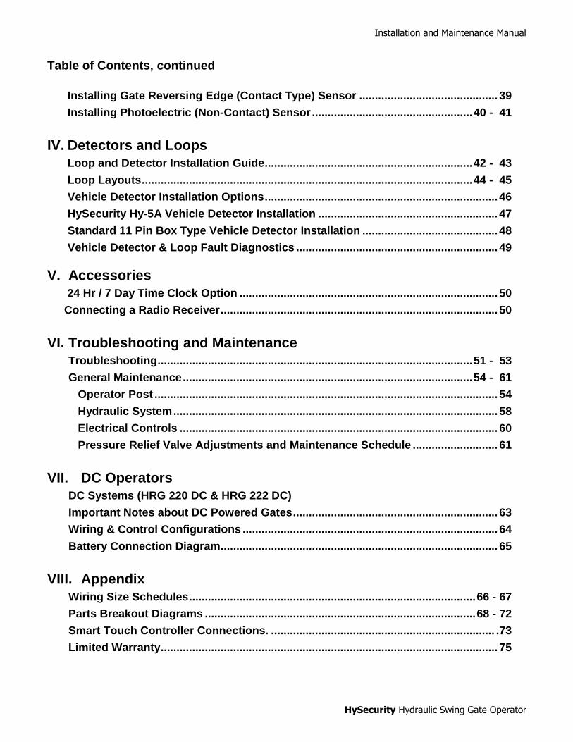
Swing Gate Post Details

Installation and Maintenance Manual
10
Swing Gate Post Details – continued

Installation and Maintenance Manual
11
Swing Gate Post Details – continued
Installation and Maintenance Manual
12
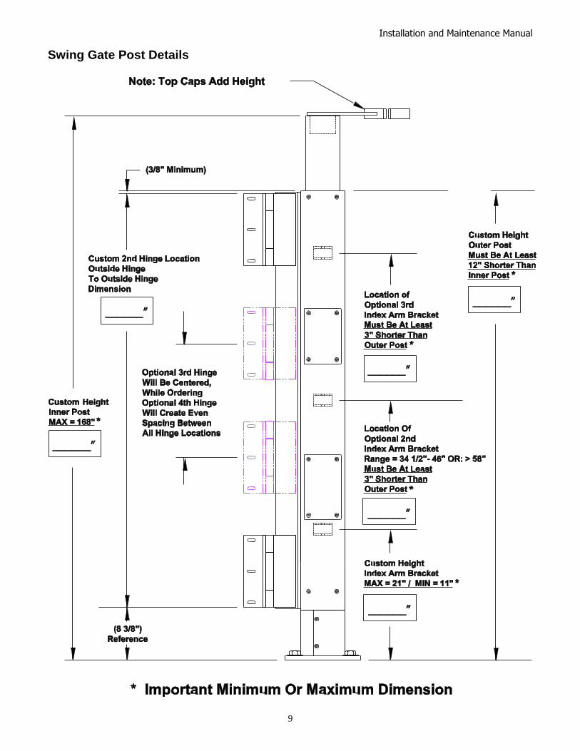
HRG 220 - Pump Pack
Installation and Maintenance Manual
13
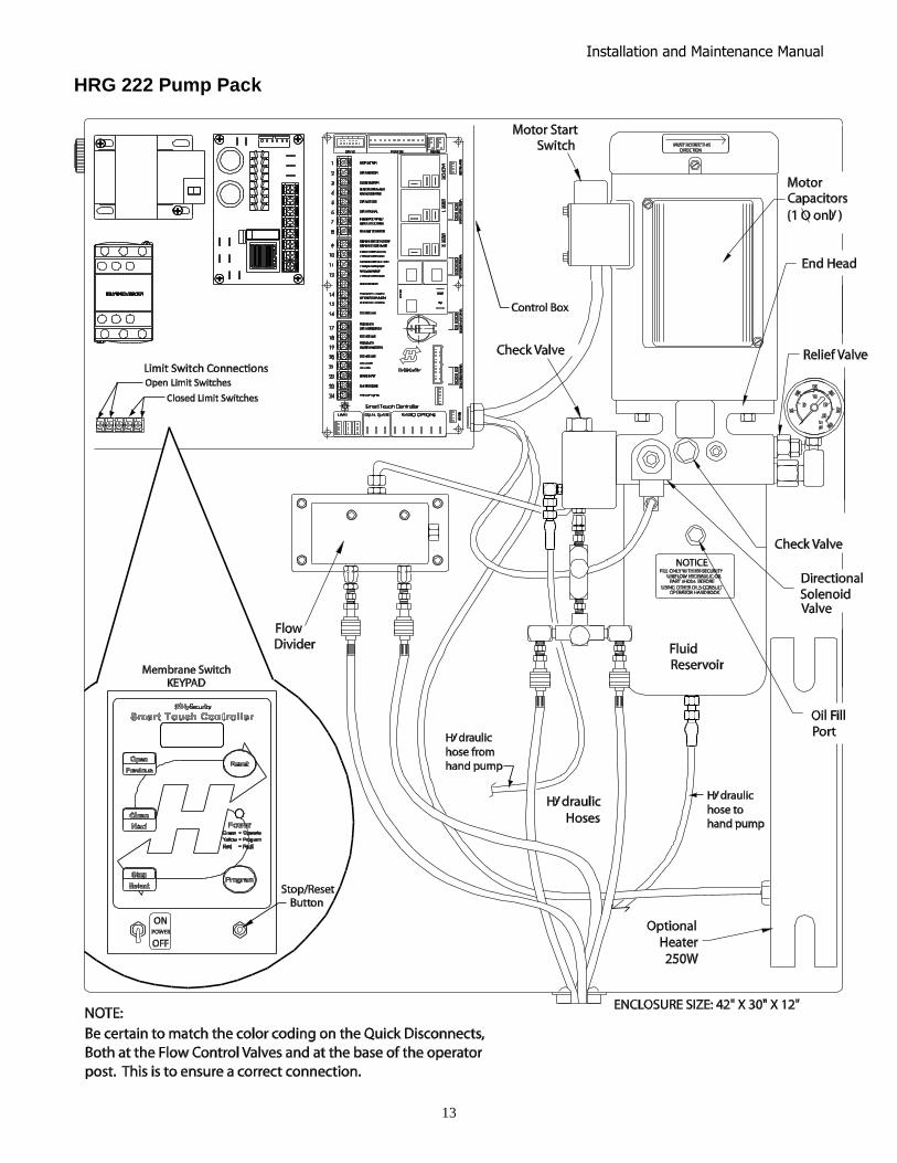
HRG 222 Pump Pack
Installation and Maintenance Manual
14
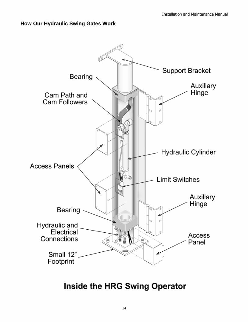
How Our Hydraulic Swing Gates Work

Installation and Maintenance Manual
15
Installation Preparation Checklist
1. Read all of the instructions, especially the Important
Information at the beginning of this manual, before you attempt installation. This section is focused upon mechanical installation. For electrical setup, skip to the section on system configuration and use of the Smart Touch Controller.
2. Check to see that the mounting slab is the right size and ready to have an operator attached. Also check that electrical conduits are correctly located to enter the operator base. HySecurity recommends the slab reaches below the local frost line and is poured together with supporting post or pilaster.
NOTE: The backing post/column, (provided by others) must accommodate all of the "tip over" loads imposed by the gate panel.
Installation Process Overview
Mount the control box and connect all conduit fittings.
Mount the operator post.
Install all accessories such as: vehicle sensing loops, access control devices, gate edge sensors or photo eyes.
Pull all wires and hoses into conduits. Note: HRG 220 comes with up to 50’ of hose for the HRG 222 with up to 150’ of hose, however, you must advise the factory on the accurate amount of hose desired or it will not be shipped with the operator.
Test the basic operator functions.
Mount the gate panel and make fine adjustments.

Installation and Maintenance Manual
16
Field Hose Measurements for HRG Operators
Note: HRG operators are usually shipped without the hoses needed to complete the system. HySecurity will make these hoses in custom lengths as required, attach the quick disconnect fittings and pre-charge the hoses with hydraulic fluid. The use of pre-charged hoses is important to avoid the introduction of air into the system. When field measuring for the necessary hose length to order, the following may be helpful: 1. There is little room in the base of the HRG operator post and limited room in the control/power panel;
therefore, your field measurements must be very accurate when calculating the length of the necessary hydraulic hoses. If your dimensions are too short, you will not reach the connections, if your measurements are too long, you will have trouble finding space for the excess hose.
2. Remember that two hoses are needed for each cylinder. This means that you need four hoses when
you are installing a HRG 222 (pair) operator.
Be sure to measure accurately the following distances: (the best way is to pull a cord through the conduit, mark it, and then measure it.)
a. The bottom of the pump/control panel to the bottom of the trench, plus 24" (61cm) b. The total distance across the trench. c. The distance back up to the bottom of the operator, plus 6" (15cm) d. The hose length inside the access panel. About 6 to 12" (15 to 30cm) is required for connections.
Check the HySecurity Price Book for the appropriate part number for the hoses.
The HRG 220 includes up to 50’ total length for the two hoses required. The HRG 222 includes up to 150’ total length for the four hoses required.
For assistance call your distributor.
#2
#2
Installation and Maintenance Manual
17
Detailed Installation Instructions for HRG Swing Gate Operator
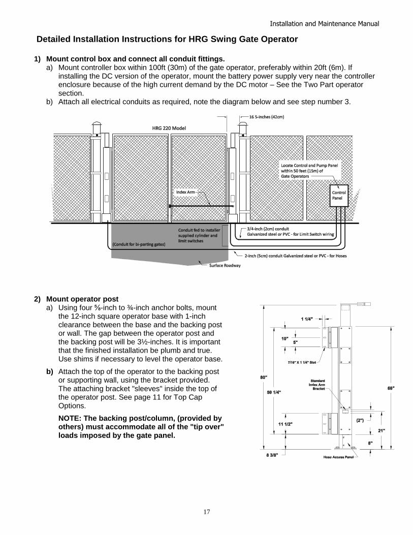
1) Mount control box and connect all conduit fittings.
a) Mount controller box within 100ft (30m) of the gate operator, preferably within 20ft (6m). If installing the DC version of the operator, mount the battery power supply very near the controller enclosure because of the high current demand by the DC motor – See the Two Part operator section.
b) Attach all electrical conduits as required, note the diagram below and see step number 3.
2) Mount operator post a) Using four ⅝-inch to ¾-inch anchor bolts, mount
the 12-inch square operator base with 1-inch clearance between the base and the backing post or wall. The gap between the operator post and the backing post will be 3½-inches. It is important that the finished installation be plumb and true. Use shims if necessary to level the operator base.
b) Attach the top of the operator to the backing post or supporting wall, using the bracket provided. The attaching bracket "sleeves" inside the top of the operator post. See page 11 for Top Cap Options.
NOTE: The backing post/column, (provided by others) must accommodate all of the "tip over" loads imposed by the gate panel.

Installation and Maintenance Manual
18
limit switches
limit switches
3) Typical conduits required at the control panel a) High voltage wires: (120, 208, 240) single
phase or (208, 240, 480) three phase, or 24VDC from Batteries. Refer to Wiring and Control Configuration for DC Operators. NOTE: 120 VAC not available on 2HP models
b) 2‖ conduit (with swept elbows) to the hydraulic post(s) for hoses.
c) 3/4‖ conduit to the post(s) for limit switches. d) Access control wires (Keypads, telephone entry
systems or any access control devices) e) Loop wires for vehicle detectors f) Other accessories such as warning lights etc.
4) Mount or install all control wiring. Loops, access
controls, and entrapment protection sensors are aspects involved with control wiring.
5) Pull and connect all wires and hydraulic hoses a) Pull four wires, 18 gauge minimum, for the limit switches from control panel to
junction area in the base of the operator post(s). This may be either by underground conduit or by a seal-tight conduit into the side of the base.
b) Remove the lower cover (at 2’ height) on the post(s) to expose the limit switches and connect the limit switch wires. The open limit switch is on the left and lower down than the close limit switch. Connect these wires to the control box at the five pole terminal strip marked open limit and close limit.
c) HRG operators normally do not ship with the hydraulic hoses included, until the exact length is specified by the installer. Refer to the HySecurity Price Book for the correct length before ordering.
d) For protection, tape the ends and pull the hoses through the 2" conduit from each post to the controller box. Connect the hoses to the couplings, being certain to match the color coded ends. Also be certain that the connectors are firmly snapped together.
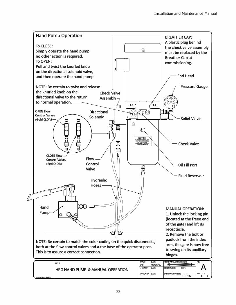
e) Remove the steel or red plastic shipping plug on the pump and replace it with the breather cap provided. (See Instructions for Hand Pump or Manual Operation.)
f) Connect the electrical power wiring to the loose wires from the On/Off switch and a grounding wire to the lower left corner of the electrical panel. Be certain the labeled voltage and phase of the operator matches the available supply. At a minimum, a 20 amp circuit (protected with a 20 Amp Inverse Time Breaker) should be provided. Also be sure the operator is electrically well grounded per NEC Article 250 and local codes. Also be certain to oversize the branch circuit wires to allow for voltage drop, especially for single-phase machines. See the wire size schedules in the appendix. Machines operating on high voltages (above 120 VAC) do not need a neutral wire.
g) Verify that the primary tap of the control transformer is connected to match the supplied voltage. It is especially important to distinguish between 208 and 230 volt supplies. The various voltage taps are identified by a label on the transformer.
6) Test and Adjust the Operator (See Smart Touch Setup First)
a) Test basic functions of the operator first, before connecting any external control wiring. If your operator is equipped with vehicle detectors, be certain that they are connected to a loop or unplugged so that they do not cause interference with the function of the machine. If the motor turns, but nothing moves, on a three phase power source, reverse two wires. Also, be certain that the hose quick connectors are firmly engaged.
b) After testing the basic functions, add accessories and external control wiring. Fully test the operator functions again.
Access panel at operator base
Access panel at operator base
Installation and Maintenance Manual
19
Mounting the Gate Panel, Index Arm, and Lock Pin Assembly
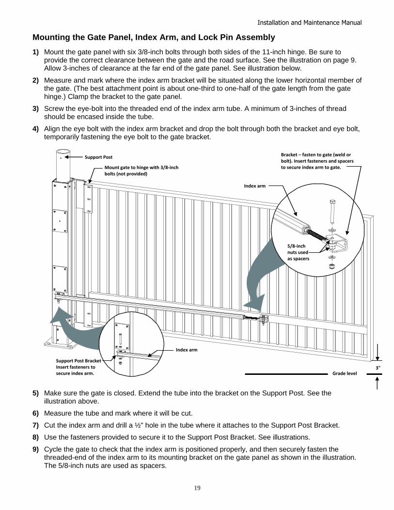
1) Mount the gate panel with six 3/8-inch bolts through both sides of the 11-inch hinge. Be sure to provide the correct clearance between the gate and the road surface. See the illustration on page 9. Allow 3-inches of clearance at the far end of the gate panel. See illustration below.
2) Measure and mark where the index arm bracket will be situated along the lower horizontal member of the gate. (The best attachment point is about one-third to one-half of the gate length from the gate hinge.) Clamp the bracket to the gate panel.
3) Screw the eye-bolt into the threaded end of the index arm tube. A minimum of 3-inches of thread should be encased inside the tube.
4) Align the eye bolt with the index arm bracket and drop the bolt through both the bracket and eye bolt, temporarily fastening the eye bolt to the gate bracket.
5) Make sure the gate is closed. Extend the tube into the bracket on the Support Post. See the illustration above.
6) Measure the tube and mark where it will be cut.
7) Cut the index arm and drill a ½" hole in the tube where it attaches to the Support Post Bracket.
8) Use the fasteners provided to secure it to the Support Post Bracket. See illustrations.
9) Cycle the gate to check that the index arm is positioned properly, and then securely fasten the threaded-end of the index arm to its mounting bracket on the gate panel as shown in the illustration. The 5/8-inch nuts are used as spacers.
Support Post Bracket Insert fasteners to secure index arm.
Mount gate to hinge with 3/8-inch bolts (not provided)
Bracket – fasten to gate (weld or bolt). Insert fasteners and spacers to secure index arm to gate.
Index arm
5/8-inch nuts used as spacers
Index arm
Support Post
Grade level 3"
Installation and Maintenance Manual
20
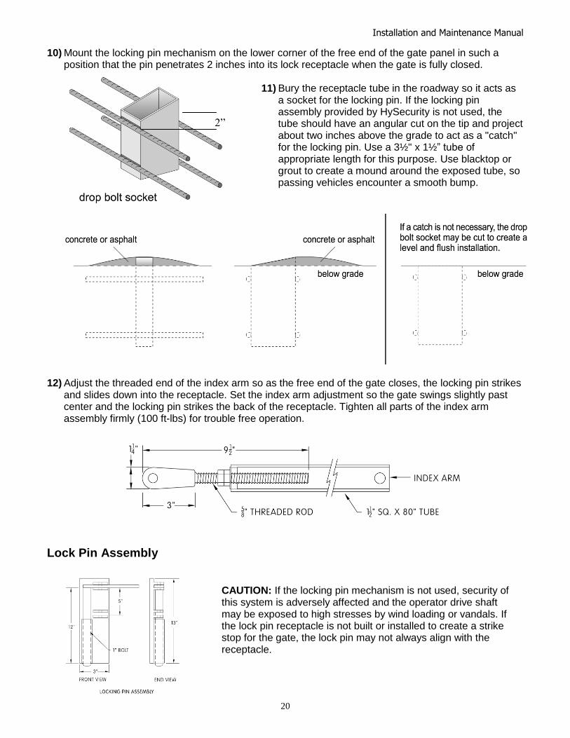
10) Mount the locking pin mechanism on the lower corner of the free end of the gate panel in such a position that the pin penetrates 2 inches into its lock receptacle when the gate is fully closed.
11) Bury the receptacle tube in the roadway so it acts as
a socket for the locking pin. If the locking pin assembly provided by HySecurity is not used, the tube should have an angular cut on the tip and project about two inches above the grade to act as a "catch" for the locking pin. Use a 3½" x 1½‖ tube of appropriate length for this purpose. Use blacktop or grout to create a mound around the exposed tube, so passing vehicles encounter a smooth bump.
12) Adjust the threaded end of the index arm so as the free end of the gate closes, the locking pin strikes
and slides down into the receptacle. Set the index arm adjustment so the gate swings slightly past center and the locking pin strikes the back of the receptacle. Tighten all parts of the index arm assembly firmly (100 ft-lbs) for trouble free operation.
Lock Pin Assembly
CAUTION: If the locking pin mechanism is not used, security of this system is adversely affected and the operator drive shaft may be exposed to high stresses by wind loading or vandals. If the lock pin receptacle is not built or installed to create a strike stop for the gate, the lock pin may not always align with the receptacle.
NOTICE: If the locking pin mechanism is not used, security of this system is adversely affected and the operator drive shaft may be exposed to high stresses by wind loading or vandals. If the lock pin receptacle is not built or installed to create a strike stop for the gate, the lock pin may not always align with the receptacle.
2”
Installation and Maintenance Manual
21
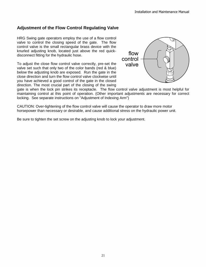
Adjustment of the Flow Control Regulating Valve
HRG Swing gate operators employ the use of a flow control valve to control the closing speed of the gate. The flow control valve is the small rectangular brass device with the knurled adjusting knob, located just above the red quick-disconnect fitting for the hydraulic hose. To adjust the close flow control valve correctly, pre-set the valve set such that only two of the color bands (red & blue) below the adjusting knob are exposed. Run the gate in the close direction and turn the flow control valve clockwise until you have achieved a good control of the gate in the closed direction. The most crucial part of the closing of the swing gate is when the lock pin strikes its receptacle. The flow control valve adjustment is most helpful for maintaining control at this point of operation. (Other important adjustments are necessary for correct locking. See separate instructions on "Adjustment of Indexing Arm") CAUTION: Over-tightening of the flow control valve will cause the operator to draw more motor horsepower than necessary or desirable, and cause additional stress on the hydraulic power unit. Be sure to tighten the set screw on the adjusting knob to lock your adjustment.
Installation and Maintenance Manual
22

Installation and Maintenance Manual
23
Smart Touch Set Up Basics of Using the Smart Touch Controller
Read this page if you are unfamiliar with using the Smart Touch Controller. The installation and commissioning of any HySecurity Gate Operator requires the setting of 1 or more menu settings within the Smart Touch Controller before an installation can be completed. Many other control settings or function changes can be made to configure the operator for your specific needs. Until a new operator has been configured, the controls are not functional and the display is locked in the menu mode until the User Class 1-4, has been selected. See the next page for instructions on how make this setting.
1. There are five buttons on the membrane switch pad that provide operational control for testing, plus programming capability during set-up. Normally, the Open, Close and Stop buttons serve as a three-button control station, but in the Menu Mode, they become Previous, Next and Select buttons. The Program Menu button is used to both enter and exit the Menu Mode. The Reset button clears all Errors or Faults that may occur and returns the control to its normal functioning state.
2. When in a Menu Mode, changes to be made to a Menu setting
are accomplished by pressing the Previous, Next and Select buttons in the following sequence:
a. Press the Next button to move forward through the list of menu items that are available or press the previous button to move back to an item that you recently passed.
b. Press the Select button if you wish to make a setting change to a menu item. The menu item will flash to indicate that its setting is ready to be changed.
c. Press Next to move forward or Previous to go back to an earlier setting choice.
d. When you have located the setting that you want to use, press the Select button and the program will accept the change and stop blinking.
e. The Program Menu button does not allow an exit to Run Mode while a selection is still blinking. Press the Select button to stop the blinking, then you may exit to Run Mode.
f. Pressing the Next or Previous buttons when the menu item is not blinking will move to the next or previous menu item.
g. When done, press Program Menu to exit to the Run Mode.
3. Once configured, the operator will be in the Run Mode. From the Run Mode, to gain access the User Menu or the Installer Menu, follow these steps:
a. Note that the Program Menu button will not function unless the gate is at rest and no open or close inputs are active. Verify system status by pressing the LED button to disclose any active inputs. There also must not be any Alerts, Faults or Errors. Press the Reset button to clear the system if necessary.

Installation and Maintenance Manual
24
b. Press the Program Menu button and watch the LCD scroll the system data, or press the
Program Menu key a 2nd time to skip the scroll.
c. The LCD display scroll will stop at the menu item for the auto close timer setting [Ct __]. This is the first item in the User Menu.
d. To access the more detailed Installer Menu, the system must first be in the User Menu, and then simultaneously press the Reset button and the Open button (early Software versions require the Reset button be pushed first and held while the Open button is pressed). The LCD will change to display the UL usage class menu item [uC __]. This is the first item in the Installer Menu.
4. Pressing the Program Menu button when the User or Installer Menu is not blinking will return the
system to the Run Mode.
Installation Configuration for Smart Touch Controller
Basic Configuration and Setting of the Usage Class
1. The hydraulic hoses must be connected to the quick couplers by matching the color coded ends
to configure the correct directional control of the gate. If the hoses are connected incorrectly, the gate will run backwards (close when open button is activated) and this may trigger an error [Err 1] on the LCD display. (The Reset button must be pushed if this happens).
2. Turn on the power switch and observe that the LCD will first show the software version, and then stop at a steady display within two seconds. If the display reads [uC 0] go to step 3. If the operator has previously been configured, the Installer Menu must be accessed in order to reach the system configuration menu items. See step 3d.
3. When turning on the power for a new machine, the LCD display directly enters the Installer Menu at the [uC __] menu item, which is for selecting the user class as defined by UL. Select [uC 1] - [uC 2] - [uC 3] or [uC 4] depending upon the use application.
4. Once the usage class is set, you should exit the Installer Menu, by pressing the Program Menu button. The LCD display jumps to the close timer [Ct__] setting in the User menu, which may now be set. Either press the Program Menu button again to exit to normal run mode or set the close timer by the same programming sequence described on the previous page.
5. Note that you cannot exit the Installer menu until the selection for the UL usage class [uC __] has been entered.
Test for normal function of the gate operator by running it both open and closed from the pushbuttons on the membrane switch pad. It is best to verify normal function before the gate panel has been mounted.

Installation and Maintenance Manual
25
Wiring Control Inputs to the Smart Touch Controller
1. Test the basic open and close operator function before wiring the external control inputs. This
makes it easier to troubleshoot if an unexpected function issue arises.
2. Each input has an LED to indicate when that input is active. a. On Classic ST Controllers, to disclose the input status, the LED button must be pushed and held.
This button is in upper left corner near the Stop input. b. On New Generation ST Controllers the LED’s are active as long as long as the AC power is
applied. On DC units, if the AC power to the charger is off, the LED button will need to be pushed to illuminate the LED. The button is in the lower left beneath the terminal strip.
3. All the control device inputs listed below are shown as a single input because the other wire is connected the Common Terminal Buss on the Power Supply board. The Emergency Close and Fire Dept. Open inputs are an exception and require a +24 Volt input in order to be activated. The +24 is available at the spade terminals next to the Common Buss.
Smart Touch Controller Inputs 1) *Stop Push button (N.C. input, jumper to Common if unused) 2) *Open Push Button (not for radio or remote access controls) 3) *Close Push button (not for radio or remote access controls) 4) Remote Open & Radio Control (For radio / remote open device -
menu opt. to also close) 5) Open/Close button (pushbutton or radio controls) 6) Partial Open (this input disabled on swing gates) 7) Open interlock input or Time clock Open (menu configurable) 8) Free Exit vehicle detector 9) Disable Free Exit vehicle detector/Timer to Close
(Free Exit is only disabled when Close Limit Switch tripped) 10) Inside Obstruction vehicle detector (Inside reversing loop) 11) Outside Obstruction vehicle detector (Outside reversing loop) 12) Shadow vehicle detector (This is the loop under the arc of the gate) 13) Edge Sensor (one input works for both directions of travel)
(14-15) Photo eye Common Power (supply for PE power & PE Com) (17) Photo eye Open direction (beam spans the area where gate opens) (19) Photo eye Close direction (beam spans across the road) (21) Charger AC power loss (only used in battery type operators) (22) Gate Lock Interlock Input (Software ≥ h3.25,-Prevents start until external gate lock releases) Classic Board = Spare Input (Software <h3.25,- non functional), (23) **Emergency Close (must menu enable and input +24 Volts to trigger) Overrides photo eyes, gate edge & vehicle detectors. (24) **Fire Dept. Open (must menu enable and input +24 Volts to trigger) Overrides photo eyes & gate edge.
* Do not connect an external control to terminals #1, 2 or 3, unless the controls are located such that there is a clear view of the entire gate area. For controls not within sight, use input terminals #4, 5, 6 or 7. **The Emergency Close and Fire Dept. Open inputs are to be
used only if access to these controls is guarded in sufficient manner such that there is always supervision when activated.
Attention
Attention

Installation and Maintenance Manual
26
New Generation Smart Touch Board
Runs software 4.xx and higher.

Installation and Maintenance Manual
27
Connecting a Master / Slave Pair
The HRG 222 is automatically programmed to operate as a master slave set. If you are installing two HRG 220’s to operate as a Master/Slave pair, the process is very simple. There is no need to order a special model or any adapters. The area of the board marked Dual Gate employs a 3-wire RS485 serial port for communication between Master and Slave operators.
1. An electrical conduit for the interconnecting wires must span between the two operators.
2. Complete the installation of both of the HRG 220 operators as separate machines and verify that their basic functions are correct as solo operators before interconnecting them.
3. The two gate operators should be supplied by home runs from separate 20 Ampere circuit breakers in the main panel, but if there is only one circuit, be absolutely certain that the breaker and wire size is sufficient for the load of two motors. See Appendix 9.
4. External control inputs, vehicle detectors and entrapment protection sensors may be connected to either gate operator without regard to preference.
5. To interconnect the two operators, route a shielded twisted pair with an internal ground wire
between the electric control boxes and connect to the RS485 Dual Gate terminals, in matching order on both machines: In the RS 485 shaded area connect the terminals for Master Com to Slave Com, Master A to Slave A and the Master B to Slave B using the insulated trio of wires. Connect the shield to a solid ground at either the Master or the Slave unit (Do not ground both ends). Cut off the shield and insulate (tape up) the exposed strands at the other operator.
6. The Installer Menu in each machine must be set as a Master or a Slave under menu item [dg__].
Set one operator as a Slave [dg_1] and the other as a Master [dg_2]. If the function of any external input is to be different than the factory default, configure for the desired function on the operator where that input is connected. Internal functions, such as the close timer or reversal distance, are controlled by the Master operator regardless of the settings in the Slave.
7. Once set as a Master or a Slave the operators will be in constant communication with each other. If that communication stops because the wires become severed or one operator is turned off, both machines will cease functioning and the LCD will display Err4, which is a Master/Slave communication error. This error cannot be reset until both machines are functional and communicating properly again.

Installation and Maintenance Manual
28
Smart Touch Controller Menu for Hydraulic Swing Gates
Initial Power Up – When power is turned on, the display will disclose the software revision:
Display Revision Number 2s delay Displays software version Number, ex. [h3.02]
System Data and accessing the User Menu Settings: If the gate is stopped in normal mode, pressing of the Menu button accesses the User Menu. After the menu button is pressed, the LCD will scroll the system data in the table below. The scrolling display stops at the close timer setting, which is the beginning of the User Menu. To exit the Menu Mode, the display must not be blinking, then simply pressing the Menu button will return the display to the Run Mode and re-enable the controls. The menu mode will also automatically return to the Run Mode if there is no activity for two minutes.
Data Displayed in Scroll Time Description S1 [SLAu] or [LEAd] 2s SLAVE Operator or LEAd Operator (master)
S2 [ot 2] Gate type (1-5) 2s Operator type: 1=HSG, 2=HRG, 3=HVG, 4=HTG
S3 [uC _] UL usage class (1-4) 2s Installer setting of usage class: type 1-4
S4 [d___] 24VDC Buss Voltage 2s Actual VDC buss voltage
S5 [CC__] Life cycle counter 2s High digits of 6 digit life cycle counter
S6 [____] Life cycle counter 2s Last 4 digits of 6 digit life cycle counter
Read through the options available in the User Menu and the Installer Menu on the next page and you can see that the functions of this gate operator can be configured to suit most any specific need. Once you have learned to navigate the menus, and how to change a menu setting, the full range of features and choices of the Smart Touch Controller are available to use. The User Menu contains the basic configuration items and the Installer Menu contains the more advanced menu items.
User Menu Options Default Description U1 [Ct 0] Close timer setting 0 0 = Close timer off or 1 – 99 seconds
U2 [hC 0] Momentary Close 0 0 = momentary, 1= Constant hold PB required
U3 [ho 0] Momentary Open 0 0 = momentary, 1= Constant hold PB required
U4 [AP 0] AC Power loss function 0 0 – 3 (0 =Type A, 1 = B, 2 = C, 3 = D)
U5 [ro 0] Radio control option 0 0 = Open only, 1 = Adds close ability when full open
U6 [bF 2] Warn before operate 2 0 =off, 1 = Buzzer alerts 3 seconds before + in motion, 2 = Buzzer alerts 3 sec before + 2 seconds in motion
U7 [FA 0] Forced open Alert and automatic gate reposition
0 0 = off, 1 sound buzzer (2 pulses/sec) if forced open for more than four seconds, time out in 30 Sec
U8 [dA 0] Drift Closed Alert and automatic gate reposition
0 0 = off, 1 sound buzzer (2 pulses/sec) if drift closed and cannot reopen within four seconds.
U9 [PE 0] Photo Eye Align Mode 0 0= off, 1 = on (auto off when close limit triggered)
U10 [CL 0] Clock set (24 hour type) 0 0= display, 1= set mins, 2= set hours, 3= day, 4= month
U11 [Ld 5] LCD Contrast set 5 1 - 9 = Adjusts contrast of the display
U12 [dS 0] Data Log (New Gen only) 0 0 = Std. 1 = Extended (reset to 0 in 24 hr) (V4.xx software)
These Notes Refer to the Menu Above:
S1 Appears only if the operator is configured as a master or a slave unit U1 Close timer setting does not appear when set for constant contact close to function U4 Power loss function only appears if factory has provided DC type operator U6 We strongly advise never disabling the Warn Before Operate buzzer.

Installation and Maintenance Manual
29
Smart Touch Controller Installer Menu Functions
The Installer Menu can be accessed only by entering the User Menu first, and then by pressing the Reset button and the Open button simultaneously. To restore the factory default settings, go to menu item [Fd_0] and change the setting to 1, then press the Program Menu button. The entire menu will reset to the factory defaults.
Installer Menu Options Default Description I1 [uC 0] Set UL Usage Class 0 0 = Gate disabled, Set Class 1 through 4 use I2 [bu 0] Choose Buzzer 0 0 = Buzzer not set, 1 = Freq 1, 2 = Freq. 2
I3 [Fd 0] Load Factory Defaults 0 0 = User settings, 1 = Load defaults (resets full menu)
I4 [dg 0] Set Master/Slave type 0 0 = Solo operator, 1 = Slave unit, 2 = Master unit I5 [Ch 0] Set AC Charger or Solar 0 0 = DC + AC charger, 1 = DC + Solar charger
I6 [Fo 0] Enable Fire Dept. Open 0 0 = input disabled, 1 = enabled I7 [oC 0] Enable Emergency close 0 0 = input disabled, 1 = enabled
I8 [SE 2] Inherent Sensor sens. 3 1 = Maximum sensitivity, 9 = Lowest sensitivity I9 [SS 0] Inherent Sensor function 0 0 = normal (see ) 1 = Stop only - Usage Class 4 only
I10 [LC 0] Leaf delay Close 0 0 = none (1-7) ½ second steps (Master/Slave only)
I11 [Lo 0] Leaf delay Open 0 0 = none (1-7) ½ second steps (Master/Slave only)
I12 [rt 0] Maximum run timer 0 0 = 60 Seconds max run, 1 = 300 Seconds max run I13 [EC 0] PEC reverse to open 0 0 = Close eye stops only, 1 = 2 sec reverse to open
I14 [EO 0] PEO reverse to close 0 0 = Open eye stops only, 1 = 2 sec reverse to close I15 [gr 0] Edge reverse to open 0 0 = Edge reverses fully open, 1 = Edge reverses for 2 sec
I16 [Sr 1] IES reverse to open 1 0 = IES reverses fully open, 1 = IES reverses for 2 sec I17 [PC 0] Set PEO/ PEC – NO/NC 0 0 = Normally Open PE output, 1 = N.C. (Supervised)
I18 [gC 0] Set Edge input – NO/NC 0 0 = Normally Open Edge output, 1 = Normally Closed
I19 [tC 1] Time clock/ Interlock input 1 0 = select Time Clock, 1 = select Open Interlock I20 [dt 0] Disable Free Exit/Close Tmr 0 0 = disable Free Exit, 1 = disable Close Timer
I21 [or 1] OOLD detector function 1 0 = pause closing only, 1 = enable reversing to open I22 [ir 1] IOLD detector function 1 0 = pause closing only, 1 = enable reversing to open
I23 [hd 1] SLD Shadow detector funct 1 0 = Hold open only, 1 = Hold closed + Hold open I24 [dL 1] Vehicle detector logic 1 1 = Std, 2 = Close timer counts down even with loops active
I25 [r1 0] User relay 1 option 1 0 = disabled, 1 – 24 = see relay output options
I26 [r2 0] User relay 2 option 6 0 = disabled, 1 – 24 = see relay output options I27 [r3 0] User relay 3 option 1 0 = disabled, 1 – 24 = see relay output options
I28 [tL 0] Gate Open alert 2 0 = 0 sec, 1= 15s, 2= 45s, 3= 75s, 4= 105s, 5= 135s I29 [Lt 0] Loitering alert 3 0 = 0 sec, 1= 15s, 2= 45s, 3= 75s, 4= 105s, 5= 135s
I30 [SA 0] System Address 0 0 = no network, 1-99 = network ―drop‖ address I31 [ELd0] Test factory ELD* 0 0=Run, 1=show freq, 2=show call level 0-7, 3=set freq 1-4
I32 [iLd0] Test factory IOLD* 0 0=Run, 1=show freq, 2=show call level 0-7, 3=set freq 1-4
I33 [oLd0] Test factory OOLD* 0 0=Run, 1=show freq, 2=show call level 0-7, 3=set freq 1-4 I34 [SLd0] Test factory SLD* 0 0=Run, 1=show freq, 2=show call level 0-7, 3=set freq 1-4
*Refer to Detector & Loop Diagnostics more information.
These Notes Refer to the Menu Above:
I1 This setting must be configured or the gate cannot function and menu will not exit.
I4 This setting appear only if the factory has provided a DC powered gate operator
I8 IES stop only setting [SS __] does not appear unless set as a class 4 operator
I9-10 These settings appear only if the Installer Menu is set for Master / Slave function
I26-27 These settings appear only if the Installer Menu has set relays r1-r3 for these alerts

Installation and Maintenance Manual
30
Description of Functions Available in the User Menu
User 1 [Ct _] Close timer setting: This menu item is the automatic close timer for the gate. The factory setting is zero, which is off. It may be configured up to 99 seconds. User 2 [hC 0] Momentary Close: This menu item is to configure for the system for constant hold push button Close function. The factory setting is zero, which is momentary contact input. User 3 [ho 0] Momentary Open: This menu item is to configure for the system for constant hold push button Open function. The factory setting is zero, which is momentary contact input. User 4 [AP 0] Power loss function: This menu item only appears if the operator is a DC battery powered version. This item is to configure what gate function will occur when the AC power fails. User 5 [ro 0] Radio control option: This menu item is to configure whether a radio input can open only (default) or if set to 1, also has the ability to close the gate when it is fully open. User 6 [bF 2] Warn before operate: This menu item controls the warn before operate buzzer and can be configured three ways. Setting the menu item to zero turns the buzzer off, but we strongly advise leaving this valuable warning feature active to alert prior to gate motion. Never cut the wires to the buzzer or unplug it. Set to 1 and the buzzer will sound three seconds before motion and the entire time during gate motion. Set to 2 (default) and the buzzer will sound three seconds before motion and for the first two seconds of motion. User 7 [FA 0] Forced open Alert and automatic gate reposition: This function is intended for highly secure facilities. If it is enabled, by setting the selection to 1, it will reinitiate a closure if a gate is somehow forced to open far enough that the close limit switch releases. The Alert buzzer will sound immediately, even if it had been turned off, and the motor will restart to secure the gate fully closed. If the gate is not fully closed within four seconds the motor turns off and the alert buzzer sounds an intruder alert for thirty seconds. The LCD display reads ALE1. User 8 [dA 0] Drift Closed Alert and automatic gate reposition: If it is enabled, by setting the selection to 1, it will restore a gate to back its fully open position if it drifts closed for any reason. The buzzer will sound a warn before operate alert, even if it had been turned off, and the motor will restart to reopen the gate. The motor will run for a maximum of four seconds and if the gate is not fully open in this period, the buzzer sounds for ten seconds and the LCD display reads ALE2. User 9 [PE 0] PE Alignment Mode: This feature may be activated as an aide to photo-eye emitter / receiver alignment. The buzzer chirps once as the photo eye is triggered or twice when the photo eye is released. The Alignment Mode is cancelled with any close limit input or reset input. User 10 [CL 0] Clock and date set: The Smart Touch Controller is equipped with a 24 hour 365 day clock, so that events of significance can be logged and stamped with the time and date. This feature is useful to record historical operation data, which can be accessed via the RS232 port. User 11 [Ld 5] LCD Contrast set: Under some extreme high or low temperature conditions, it may be necessary to adjust the contrast of the LCD display. The display is adjustable from 0-9 with a factory default setting of 5. User 12 [dD 0] Extended Data Log: When set to 1 the ST Controller logs additional events within the Smart Touch Controller in addition to the normal error and alert logs. This parameter resets to 0 automatically after 24 hours – (Requires New Generation Smart Touch board and V4.xx software)

Installation and Maintenance Manual
31
Description of Functions Available in the Installer Menu
Installer 1 [uC 0] Set UL Usage Class: This menu item is used to set the UL usage class, which must be set by the installer before the operator will function. Installer 2 [bu 0] Select Buzzer Type: This menu item selects the type of audible buzzer installed on the machine. To set, push SELECT on the keypad, the display will flash 0, push OPEN and note the buzzer volume. Push OPEN again and note the buzzer volume. If this tone is louder, push SELECT, if the first tone was louder, push CLOSE for the louder tone, then push SELECT to lock in the louder tone. Installer 3 [Fd 0] Load Factory Defaults: This menu item is used to globally restore all menu settings back to new machine status. To activate, change the setting 0 to 1 and push the Menu button. The UL usage class and the hand configuration will need to be set again. Installer 4 [dg 0] Set Solo, Master or Slave type: This menu item is used to configure an operator as a Master or a Slave operator in Master/Slave paired gate installations. Installer 5 [Ch 0] Set AC Charger or Solar: This menu item appears on 24 VDC battery machines only and is set to solar only when there is no AC battery charger. Installer 6 [Fo 0] Enable Fire Dept. Open: This menu item is used to enable the Fire Dept. Open input. When set to [Fo_1] this input will override vehicle detectors, photo eyes and gate edges to open a gate. A reset is required before the gate can be closed. Installer 7 [oC 0] Enable Emergency Close: This menu item is used to enable the Emergency Close input. When set to [oC_1] this input will override vehicle detectors, photo eyes and gate edges to close a gate. A reset is required before the gate can be opened. Installer 8 [SE 6] Inherent Sensor sensitivity:. This menu item is to adjust the sensitivity of the internal inherent sensor. Available settings are 1-9, with 9 being the least sensitive. Installer 9 [SS 0] Inherent Sensor function: This menu item is only available in UL class 4 operators and allows an option whereby the inherent sensor will only stop the gate. (No reversal in either direction – overrides Installer 16.) Installer 10 [LC 0] Leaf delay Close: This menu item only appears if the operator is set up as a Master or a Slave. Available settings are 1-7. Each increment adds ½ second, to a maximum of 3 ½ seconds time delay, before the operator activates when commanded to close. Installer 11 [Lo 0] Leaf delay Open: This menu item only appears if the operator is set up as a Master or a Slave. Available settings are 1-7. Each increment adds ½ second, to a maximum of 3 ½ seconds time delay, before the operator activates when commanded to open. Installer 12 [rt 0] Maximum run timer: The maximum run timer has a default setting of 60 seconds. This menu item allows an optional setting of 300 seconds, if changed to [rt_1]. Installer 13 [EC 0] PEC (photo eye close) reverse to open: The default for this menu item is for non-reversal if the close photo eye is triggered. The optional setting of [EC_1] will cause the gate to reverse to open for two seconds if triggered while closing. Installer 14 [EO 0] PEO (photo eye open) reverse to close: The default for this menu item is for non-reversal if the open photo eye is triggered. The optional setting of [EO_1] will cause the gate to reverse to close for two seconds if triggered while opening. Installer 15 [gr 0] Edge reverse to open: The default for this menu item is for a 2 second reversal if the gate edge is triggered. The optional setting of [gr_1] will cause the gate to reopen fully if triggered while closing.

Installation and Maintenance Manual
32
Description of Functions Available in the Installer Menu
Installer 16 [Sr 1] IES (inherent sensor) reverse to open: The default for this menu item is for a 2 second reversal if the inherent sensor is triggered. The optional setting of [Sr_1] will cause the gate to reopen fully if triggered while closing. Installer 17 [PC 0] Set PEO/ PEC – NO/NC: The default for this menu item is for photo eyes with Normally Open outputs. The optional setting of [PC_1] will require a Normally Closed output. If set for N.C. the connection is also supervised and any open or short circuit fault will generate a FAL2 alert, which requires a Stop button reset to re-enable any function if triggered. Installer 18 [gC 0] Set Edge input – NO/NC: The default for this menu item is for edge sensor with Normally Open outputs. The optional setting of [gC_1] will require a N.C. output. Installer 19 [tC 1] Time clock / Interlock input: This menu item configures the input at terminal #7 to be either for the gate interlock function, or for an external time clock to open input. The default setting is [tC_1] for the interlock function. Installer 20 [dt 0] Disable Free Exit / Close timer: This input configures the input at terminal #9 to disable either the Free Exit Detector on terminal #8, or the Timer To Close function. Default setting is [dt 0] allowing disabling of the free exit detector. Installer 21 [or 1] OOLD (Outside Obstruction loop detector) function: The default for this menu item is for full reversal when the OOLD is triggered. The optional setting [or_0] causes the gate to only pause when triggered. Closure begins as soon as the loop is clear again. Installer 22 [ir 1] IOLD (Inside Obstruction loop detector) function: The default for this menu item is for full reversal when the IOLD is triggered. The optional setting [ir_0] causes the gate to only pause when triggered. Closure begins as soon as the loop is clear again. Installer 23 [hd 1] SLD (Shadow loop detector) function: The default for this menu item allows the shadow loop to prevent the swing gate from opening if triggered. The optional setting [hd_0] causes the shadow loop to only prevent closure of the gate. Installer 24 [dL 1] Vehicle detector logic: This menu item is used to configure quick close logic. For swing gates, there are two modes. Mode 1 is standard logic. Mode 2 allows a faster closure by allowing the close timer to count down even when a detector loop is active. Installer 25, 26, 27 [r1 0], [r2 0], [r3 0] User output relays 1 - 3 programming options: These three menu items are used to configure the function of the three user output relays. There are 19 optional choices, which are described in detail in Options for User Programmable Output Relays 1-3. Installer 28 [t L 0] Gate Open alert: This menu item is to adjust the time delay before activating the user relay function #8, described in Options for User Programmable Output Relays 1-3. Time settings up to 135 seconds. Installer 29 [Lt 0] Loitering alert: This menu item is to adjust the time delay before activating the user relay function #13, described in Options for User Programmable Output Relays 1-3.Time settings up to 135 seconds. Installer 30 [SA 0] System Address: Set the system address for network communication. 0 = no network communication, 1-99 set individual poling addresses. Requires v4.24 software or higher. Installer 31 [ELd0] Factory ELD: Controls the HY-5A Free Exit detector. Installer 32 [iLd0] Factory IOLD: Controls the HY-5A IOLD detector. Installer 33 [oLd0] Factory OOLD: Controls the HY-5A OOLD detector. Installer 34 [SLd0] Factory SLD: Controls the HY-5A Shadow detector. Refer to Detector & Loop Fault Diagnostics.

Installation and Maintenance Manual
33
Optional Wiring
If alternate output functions are required, see Options for User Programmable Output Relays 1-3. NOTE: User 3 is rated for DC only up to 48VDC and does not have a NC connection. Connecting an Interlocked Pair: An interlocked pair of operators is not a Master/Slave system, but is simply two gate operators interlocked such that the one cannot open unless the other is fully closed. This connection is used frequently at correctional facilities for Sally Port gates. The Smart Touch Controller provides both an interlock input (#7) and the interlock output contact that is required.
1. User relay 3 on the Smart Touch Board has been set by the factory to provide the necessary interlock function. Connect a total of four wires between operator #1 and operator #2 as follows: One wire to the Common buss of each operator to the User 3 relay COM terminal of the other operator. Then, connect wires from the User 3 relay NO terminal to the Interlock input (#7) of the other operator.
2. If User relay 3 has already been used for a different function, then one of the other relays User 1 or User 2 must be wired as described above and set to output function 1. The user relays are configured in the Installer Menu as item [r1__], [r2__] or [r3__] according to the definitions described in Options for User Programmable Output Relays 1-3.
3. The interlock input, terminal #7, is convertible to alternately be a time clock input, so it is possible that it may need to be switched back for the interlock function. If this alteration is needed, go to the Installer Menu, and set item [tC _] to be [tC_1].
Connecting to an External Lock Mechanism: An external solenoid lock or maglock can be controlled by the Smart Touch Controller to unlock just before gate motion begins.
1. User relay 2 has been set by the factory to provide the necessary output for a solenoid lock. Connect the voltage matching the lock solenoid to User 2 COM and connect a solenoid coil to User 2 NO (connect a maglock coil to User 2 NC). The un-switched solenoid or maglock wire connects directly to its supply voltage common conductor.
2. If User relay 2 has already been used for a different function, then one of the other relays User 1 or User 3 must be wired as described above and set to output function 6. The user relays are configured in the Installer Menu as item [r1__], [r2__] or [r3__] according to the definitions described in Options for User Programmable Output Relays 1-3.
Connecting the Gate Secure Position Indicator Output: An external device can be signaled by the Smart Touch Controller to indicate the gate is secure.
1. User relay 1 has been set by the factory to provide the necessary output for position indication. Connect the voltage matching the indicator light to User 1 COM and connect the gate secure light to User 1 NC. The other indicator light wire connects directly to the voltage common conductor. If an unsecured light is required, connect it to User 1 NO.
2. If User relay 1 has already been used for a different function, then one of the other relays User 2 or User 3 must be wired as described above and set to output function 1. The user relays are configured in the Installer Menu as item [r1__], [r2__] or [r3__] according to the definitions described in Options for User Programmable Output Relays 1-3.

Installation and Maintenance Manual
34
Options for User Programmable Output Relays 1-3
The Smart Touch Controller can interface with several types of external devices through the use of its programmable output relays. All of the output functions listed below are accessible in the Installer Menu under the selection [r1 __], [r2 __] and [r3 __]. Select which relay you wish to use and enter the appropriate function by the numbers as listed below. Note: The User Relays will operate normally to less than 18VDC
1. Close Limit output: This output can also be used to create an interlock signal to another operators interlock input, or simply to indicate that the gate is secure. The relay is released at full closure.
2. Close limit pulse output: This output may be used in a sequenced system to command a 2nd
machine to close. Generates a brief pulsed output that occurs when the close limit is triggered.
3. Open limit output: This output is used to indicate a full open position indication. This output becomes active when to open limit is triggered and releases when the open limit is released.
4. Open limit pulse output: This output may be used to trip a sequenced barrier arm gate operator to open. Generates a brief pulsed output occurs when the open limit is triggered. An additional pulse is also generated with any new open command even when the gate is already fully open.
5. Warn before/during operate output: This output may be used to control an external warning device. This output will operate at the same time as the internal warn before operate buzzer.
6. Gate Lock output: This output may be used to control external solenoid locks or magnetic locks. In both directions of travel, this output will be activated about 7/10
th of a second before the operator starts moving the
gate, and remains active while moving and for a few seconds after stopping.
7. Gate forced open output: Alarms if the gate is forced off the closed limit switch, and operator is not able to restore the gate to full close within four seconds. This alarm resets itself in 30 seconds.
8. Gate open too long output: Activates when the gate has been open longer than a user-selected period of time. Adjustable from 0 delay, then 15 seconds delay to 135 seconds delay in 15 second time increments.
9. Safety Mode Alert output: Activated when system is in the Safety Mode or the Entrapment Mode. Safety Mode occurs upon an impact with an obstruction. Entrapment Mode means the gate is stopped and occurs if the internal inherent sensor triggers while the system is in the Safety Mode.
10. Entrapment Mode Alert output: Activated only when system is in the Entrapment Mode.
11. Unauthorized Vehicle Entry output: Activated when a 2nd
vehicle enters from the outside, without a valid input from an access control device. This output releases when an access control input signals open or the gate reaches the close limit position.
12. Outside Obstruction Vehicle Detector output: This output may be used to interlock to an entry device to prevent pedestrian use. This output is active whenever the OOLD is tripped.
13. Special output from “OOLD” only when gate is closed: Used to annunciate a vehicle or to indicate loitering. Adjustable from 0 delay, then 15 to 135 seconds delay in 15 second time intervals.
14. Gate nearing full travel output: For operators with RPM sensors only. This output is activated when the gate is three feet from full travel in both the open and close directions. This output can be used to reduce the sensitivity of a proximity sensor near the ends of gate travel.
15. Gate Failure output: This output is activated to report that a problem has occurred. Indicates that system in an Error Mode, Fault Mode or Entrapment Mode. If active, the gate is disabled.
16. Motor Running output: This output is active when the motor is running and the gate is in motion.
17. AC Power Failure output: This relay is normally energized, but drops with loss of AC power. This output is also active on DC machines when the battery charger is off.
18. DC Power Failure output: This output is activated when the battery power is very low, but the output ceases when the battery is dead. The relay is triggered when the battery is less than 20 Volts.
19. Flasher Relay: This output is intended to control flashing lights that pulse once per second. The relay is activated all the time, except when the open limit switch is triggered.

Installation and Maintenance Manual
35
20. Free Exit Loop Vehicle Detector (ELD) output (available with h3.23 and higher software): This output is active whenever the ELD is tripped.
21. Inside Obstruction Vehicle Detector (OOLD) output (available with h3.23 and higher software): This output may be used to interlock to an exit device to prevent pedestrian use. This output is active whenever the IOLD is tripped.
22. Shadow Loop Vehicle Detector (SLD) output (available in h3.23 and higher software): This output is active whenever the SLD is tripped.
23. Gate Lock Output (available in h3.25 software): External gate lock output. Activates at initiation of open cycle and remains on for 10 seconds. Similar to #6 but shuts off after 10 seconds.
24. Gate at Partial Open Position (available in h3.25 and higher software): This output is active when the partial open position is reached or exceeded.
Clock Functions
Setting the Time and Date The Smart Touch Controller is equipped with a 24 hour (military time), 365 day clock, so that events of significance can be logged and stamped with both the time and the date. This feature is useful to record key historical operational data and a log of Alerts, Faults and Errors all of which can be accessed via the RS232 port. Optional software and a serial communication cable are required in order to read this data*.
1. To set or adjust the time, go the User menu item [CL_0] and push the Select button, so that [CL_0] blinks. Using the Previous and/or Next buttons, change the setting from [CL_0] to 1, 2, 3 or 4 depending upon which setting is to be changed. 1 = minutes / 2 = hours / 3 = days / 4 = months.
2. Push the Select button. The display will change to a blinking (adjustable) value. Different displays will appear (see table below) based on which [CL] value is selected:
Setting Value Display
[CL 1] minutes [ni 0–59]
[CL 2] hours [hr 0–23]
[CL 3] days [dA 1-31]
[CL 4] months [no 1-12]
[CL 0] Run Mode None
3. Change the hour, minute, day or month to the desired value using the Previous and/or Next buttons,
then press the Select button to enter the change. [CL 0] will appear. 4. To change another setting, Press the Select button, (display will blink), then move to that setting
using the Previous and /or Next buttons and repeat steps 2 and 3 until the clock is fully set.
5. When finished, be sure [CL 0] is displayed, then push MENU to exit. 6. A lithium disk battery supports the clock so that the time is not lost when the main power is off. This
battery should be replaced about every five years. Use a DL 2025 / DL 2032 or CR 2025 / 2032 battery.
* START Configuration and Diagnostic software is available at no charge from our website – www.hysecurity.com. Serial communication cables as well as Serial to USB adaptors (if needed) are available through HySecurity distributors (Cable and USB Adaptor Kit) .

Installation and Maintenance Manual
36
Entrapment Protection Device Schematic for Swing Gates
This schematic view is not meant to recommend the only way to set up your configuration, but to point out the various elements of a proper automatic vehicular gate installation. The gate operator itself is only the one component in the total system. Always install a separate pedestrian gate.

Installation and Maintenance Manual
37
Gate Operator Category
Horizontal Slide, Vertical Lift, Vertical Pivot Swing and Vertical Barrier (arm)
Usage class Primary typea Secondary typea Primary typea Secondary typea
Vehicular I and II A B1, B2, or D A, or C A, B1, B2, C, or D
Vehicular III A, B1, or B2 A, B1, B2, D, or E A, B1, or C A, B1, B2, C, D, or E
Vehicular IV A, B1, B2, or D A, B1, B2, D, or E A, B1, C, or D A, B1, B2, C, D, or E Note—The same type of device shall not be utilized for both the primary and the secondary entrapment protection means. Use of a single device to cover both the opening and closing directions is in accordance with the requirement; however, a single device is not required to cover both directions. A combination of one Type B1 for one direction and one Type B2 for the other direction is the equivalent of one device for the purpose of complying with the requirements of either the primary or secondary entrapment protection means. aEntrapment protection sensor types: Type A - Inherent entrapment sensing systems. Type B1 - A non-contact sensor (photoelectric sensor or the equivalent). Type B2 - A contact sensor (edge sensor device or the equivalent). Type C - Inherent adjustable clutch or pressure relief device. Type D - An actuating device requiring continuous pressure to maintain opening or closing motion of the gate. Type E - An inherent audio alarm, which warns a minimum of 3 seconds before operation.
UL Usage Class Information:
The automatic vehicular operator must also be labeled as appropriate for both the type and usage class of the gate. Installers must verify that the gate operator is labeled for the intended application. Note: Sliding gate operators installed in Class I & II applications must not move the gate faster than 12 inches per second. Class I: Intended for use in a home of one to four single family dwelling, or a parking area associated therewith. Class II: Intended for use in a commercial location or building such as a multi-family housing unit (five or more single family units) hotel, garages, retail store or other building servicing the general public. Class III: Intended for use in an industrial location or building such as a factory or loading dock or other locations not intended to service the general public. Class IV: Intended for use in a guarded industrial location or building such as an airport security area or other restricted access locations not servicing the general public, in which unauthorized access is prevented via supervision by security personnel.

Installation and Maintenance Manual
38
Placement and Use of Secondary Pedestrian Entrapment Sensors
WARNING: To reduce the risk of serious injury or death, read and follow all instructions in the gate operator handbook and on the warning labels. Automatic gate operators are intended only for vehicular use and pedestrians must be routed to a separate man gate, however sensors are still required in order to provide a degree of protection should anyone happen to stray into the area of an automatic gate. Generally there are two types of external sensors that may be used: Contact type sensors, such as an edge sensor, and non-contact sensors, such as photoelectric eyes. Current industry standards require the use of either type or both of these sensors, as a secondary device, in Class I and Class II automatic sliding gate installations, because the general public is likely to be present. Although there are alternatives for Class III and IV installations, we highly recommend the use of external sensors for all automatic gate applications.
The specifier or installer may choose either photoelectric eyes or edge sensors, or use these devices in combination, but both the open and closing directions of gate travel must be guarded. The UL 325 standard for automatic sliding gates specifically requires the following:
One or more non-contact sensors (photoelectric eyes) shall be located where the risk of entrapment or obstruction exists, such as the perimeter reachable by a moving gate.
One or more contact sensors (edge sensors) shall be located at the leading edge, and bottom edge of a swinging gate that has more than 6‖ clearance to the road.
A hardwired contact sensor shall be located and its wiring arranged so that the communication between the sensor and the gate is not subjected to mechanical damage.
A contact sensor that transmits its signal to the gate operator shall be located such that the signal is not impeded by building structures or other obstructions and shall function under its intended end-use conditions.
The contact and non-contact sensors must be tested and labeled as ―Recognized Components‖ under the UL 325 standard in order to be deemed acceptable for use in this application.
Study the entrapment protection schematic and consider your specific installation to determine where the greatest risk of entrapment exists. Locate the edge sensors and/or the photoelectric sensors accordingly. Be certain that a sufficient number of sensors are used so that both directions of gate travel are guarded.

Installation and Maintenance Manual
39
Installing Gate Reversing Edge (Contact Type) Sensor
1. Follow the guidelines in the Entrapment Protection Schematic to plan the most appropriate mounting positions for the edge sensors to be installed. For swinging gates. one or more contact sensors (edge sensors) shall be located on the inside and outside leading edge, and on the bottom edge of a swinging gate that has more than 6‖ clearance to the road. A requirement of the UL 325 standard is that an edge sensor be laboratory tested and ―recognized‖ under UL 325.
2. Drill holes through the edge’s mounting channel and through the surface that each gate edge is to
be mounted. Securely fasten every edge sensor. Vertically mounted edge sensors should all be placed not higher than 6‖ above the ground.
3. Edge sensors that are not attached to the moving gate, such as post mounted sensors are wired in parallel and directly connected to the gate operator:
a. If the gate is swinging open to a wall with less than 16‖ clearance, mount a gate edge to the wall that aligns with the gate when it is in the open position.
b. Always route the leads of the edge sensors to the gate operator so that they are protected from physical damage.
c. Connect one edge sensor lead to our common buss on the power supply board and the other to terminal #13, which is labeled Edge Sensor input.
4. Edge sensors may be used with an edge transmitter and a receiver in order to transmit to the
gate operator. We do not recommend the use of retractable cord reels or curl cords because of durability problems with these devices in outdoor environments.
a. Mount gate edge sensors to the leading edge and bottom edge of the gate so that entrapment protection is provided in both directions of travel.
b. Mount one or two edge transmitters (Linear Model #3022 or equivalent) onto the gate panel near the upper corner of the leading edge of the gate. All gate edges will function correctly if only one transmitter is used, but wiring multiple edges to a single transmitter may be impractical or displeasing visually.
c. Connect the edge(s) to the terminals in the edge transmitter and set the DIP switches of the transmitter to match the setting in the receiver to be used.
5. Mount a commercial style radio receiver* (external antenna type) on the inside of the operator, below the electrical box. Knock out the smallest hole in the lower right corner of the electrical box and route the wires to the area marked Radio Options. Only three wire connections are needed because the 24-Volt supply and the radio output share a wire. Being certain to observe polarity, crimp the black radio power wire together with one of the radio output wires into a .25‖ spade connector and connect to the COM terminal. Connect the red wire to the +24V terminal and connect the other radio output contact wire to the spade marked EDGE. Note that this terminal is the same as the #13 input terminal labeled Edge Sensor on the main control board.
a. Mount an external antenna onto the top of a fixed post of the fence near the operator. b. Connect the antenna into the socket on the radio receiver. c. Set the DIP switches in the receiver to match the same code used in the transmitter.
6. Test the operation of the reversing edge to make sure that it is functions correctly. Advise the
user of the gate to be certain to retest this vital function weekly.
* If there is also to be a radio receiver for a hand held transmitter to operate the gate, be certain to use a two channel commercial receiver. Remember that the transmitter and receiver must have their codes set the same or they will not function.

Installation and Maintenance Manual
40
Installing Photoelectric (Non-contact) Sensors
General Information: Follow the guidelines in the Entrapment Protection Schematic to plan the most appropriate mounting positions for the photo-eye sensors to be installed. If there are no other secondary external entrapment protection sensors (typically an edge sensor), at least two photoelectric sensors are required to serve to reverse the gate in each direction of travel. The Smart Touch Controller has two photoelectric sensor inputs (Photo eye open and Photo eye close). There are two common types of photoelectric sensors, thru beam and retro-reflective, each has some advantages. A thru beam sensor is generally more powerful and able to function reliably with dirty optics and in poor weather. A retro-reflective sensor has the convenience of not requiring the installation and electrical wiring of the remote emitter required in a thru beam system, but is generally more problematic in poor weather. Avoid use of a retro-reflective device to span a distance greater than 24 feet in an outdoor environment or performance will probably be unsatisfactory. Compatibility: A requirement of the UL 325 standard is that a photoelectric sensor be laboratory tested and ―recognized‖ under UL 325. In order to be compatible with a HySecurity operator, a photo eye must be rated to function from 24 Volts DC source power. Installation: Mount the photo eyes approximately 15‖ to 30‖ above the ground and as close to the gate as possible. Unless there are also gate edges for entrapment protection, a minimum of two photo eyes will be required to function for both the open and closing directions of travel. Mount the receivers on the left and right sides of the gate operator and the emitters just beyond the travel of the gate in both the full open and full closed positions of travel. In some situations, an additional photo eye should be installed on the public side of the gate. The installation locations described above are intended for pedestrian detection, if photo eyes are also to be used for vehicular detection, consider, in addition to the low elevation photo eye for cars, another photo eye at a height of about 55‖ to detect semi-trucks. Configuration: If the photo eye has an internal switch for setting Light Operate vs. Dark Operate, select Light Operate. If the photo eye has a relay output and has both NO and NC terminals, some experimentation may be required to determine the proper connection. This is because in the Light Operate mode the output relay is normally energized and releases when the beam is blocked. Some manufacturers label an output as NO, when it is actually an NC contact. If the photo eye has a solid-state output and provides the option of a sinking or sourcing connection, choose the sinking connection. Connection: Three wires to the receiver and two wires to the emitter are all that is required.
a. The +24 Volt source power is obtained from our power supply board. b. The –24 Volt source power is obtained from our terminals #14 or 15, labeled (Photo Eye
Power) on the Smart Touch Controller board. Note: The –24 Volt Photo Eye Power also supplies the photo eye Common.
c. The photo eye NO or NC output connects to the Smart Touch Controller board at terminal #19 if the photo eye spans the road, or at terminal #17 if the photo eye spans the gate’s open position storage area.

Installation and Maintenance Manual
41
Installing Photoelectric (Non-contact) Sensors (continued)
Supervised Connection: If the photo eye being installed has a true NC output (one that is NC when the photo eye is powered, aligned and set for Light Operate) then a supervised connection is recommended. A supervised connection will signal a system Fault and prevent gate operation if either the open or close photo eye connection ever becomes an open circuit or a short circuit. The Installer Menu item [PC_0] must be changed to [PC_1] to enable this feature. See Description of Functions available in the Installer Menu. Photo Eye Function: A tripped photo eye will prevent the gate from starting in either direction if the gate is stationary. If tripped while in motion, the standard function is to pause the gate motion and then automatically restart again if the photo eye is clear within five seconds. An optional setting in the Installer Menu will cause a 2 second reversal of travel. Alignment: Most photo eyes require careful optical alignment in order to aim the emitter beam to the center of the receiver or reflector. In order to avoid false triggering, it is important to carefully align the system, especially with retro-reflective photo eyes. The best way to assure true centering of the beam is with some trial testing where the emitter is shifted to move the beam left and right and up and down until the range of the invisible cone of the infrared beam is known. Photo eyes usually provide alignment aid LED’s for this setup, but they can be hard to see. HySecurity has provided a unique feature that causes our buzzer to chirp when the photo eye enters and exits alignment. See User menu 9. Set the Installer menu item [PE_0] to [PE_1] and the buzzer will provide an audible indication both when the beam is broken and remade. Notes about retro-reflective systems: Correct installation and alignment of a retro-reflective photo eye and its reflector is important for a trouble free installation. Any system operating at a range greater than 16 feet is more prone to false triggering due to dirty optics, condensation or poor weather. If care is taken in the initial mounting and alignment of the 3-inch reflector, the chance of problems is greatly reduced. Taking steps to protect the photo eye and the reflector from being exposed to fog and being absolutely certain the photo eye is perfectly aligned will greatly reduce any false triggering of the system. The ideal mounting of a retro-reflective photo eye is inside and enclosure of some sort. The ideal mounting for the reflector is suspended inside a twelve-inch long piece of 3-inch PVC conduit. Cut the opening of the PVC conduit at a 45-degree angle to act as a drip shield. Hold the reflector against the backside of the PVC conduit by attaching a 3-inch male connector. Do not cement the connector, so that the reflector can be reached for future cleaning. To create a mounting base, attach a 3-inch aluminum flange (electric meter hub) to the connector. This whole package can be mounted to any flat surface. Locate the reflector in the center of the invisible beam of infrared light to achieve the most sensitive alignment. The beam center is determined by the following test: while holding the reflector in your hand, slowly raise it until the beam is no longer returned, and the photo eye trips. Mark this maximum height. Now lower your hand and determine the lower limit of the infrared beam by watching for the trip point. Mark this position as well. Repeat the same procedure for left and right at the center elevation of the beam, as determined by the previous test. Once the four limits have been determined, either mount the reflector in the center of the area outlined or realign the eye for the position of the reflector. If the photo eye is realigned, be sure to perform the centering test again to verify that the reflector is truly in the center. A last tip – if you coat the reflector with common dishwashing detergent, or some other anti-fogging compound, it will reduce fogging from atmospheric moisture.

Installation and Maintenance Manual
42
Detector Installation Guide
Detector Basics The vehicle detector passes a small current flow through the ―loop‖ which then becomes an inductive coil. When a vehicle passes over a loop the detector senses the resultant drop in the inductance, and actuates the detector output. Loop Configurations Configurations differ depending on the application. In parking applications with our HTG 320 operator, a loop may be as small as 3’ x 6’. In traffic applications employing one of our sliding gate operators, or swing gate operators, the smallest loop should not be less than six feet square. Rules to Follow for Security Gate Applications 1. The side of the loop closest to the gate shall be located at least four (4) feet distant from its line of
travel. 2. The shortest side of the loop shall be between six (6) and eight (8) feet in length. The longest side of
the loop shall be between six (6) and twenty (20) feet in length. For applications that need to span a wide area, use several smaller loops. Do not exceed a maximum of 200 square feet of loop area to only one detector.
3. In applications with multiple loops, keep each loop at least six feet apart. This avoids ―cross talk‖. It
is possible to have loops closer together by selecting different frequencies. An advantage of using HySecurity model HY-5A detectors is that problematic ―cross talk‖ is not possible.
4. For greater sensitivity and less chance of false calls caused by the motion of the gate, it is better to
use two smaller loops, connected in a series circuit, to one detector instead of one large, single loop. 5. To avoid interference, keep loops at least two (2) inches above any reinforcing steel. Do not route
loop wires with, or in close proximity to, any other conductors, including other loop leads, unless shielded lead-in cable is used.
6. Loop and lead-in wire should be one continuous piece. Avoid splices, if possible. If a splice is
necessary for any reason, ―pot‖ the splice in epoxy or use heat shrink to ensure that the quality of the splice covering is the same as the original wire jacket.
7. Use only 14, 16 or 18 gauge stranded wire with a direct burial jacket. Cross linked polyethylene
insulation types, such as, XLPE or XHHW, will last much longer and are less prone to damage during installation than conventional insulation types. Preformed loops can be used before road surfacing or under pavers.
8. Twist loose tails of lead-in wires tightly, approximately ten times per foot.

Installation and Maintenance Manual
43
Detector Installation Guide, continued
9. Follow this guide for the correct number of wire turns according to the perimeter size of the loop: 10 to 13 lf. = 5 turns 14 to 26 lf. = 4 turns 27 to 45 lf. = 3 turns 46 to 100 lf. = 2 turns
10. This guide is written from a design perspective, but installation workmanship practices are equally
important to insure proper operation and long loop life. The best way to insure a quality installation is to employ a professional installer experienced with detector loops. A few important practices are: The slot in the surface should be cut ¼‖ wide x 1 ½‖ deep. The corners of the cut must be at an angle or core drilled to relieve stress on the wires. After the wire is installed, the slot must be completely backfilled with a non-hardening sealer.
Note that if the loop wires are able to move in the slot after the sealer has set, the detector may give false calls.
Detector Logic HySecurity Gate Operators recommends that vehicle detectors be used for free open and obstruction sensing logic only. The exception is in parking applications with our HTG320 operator where detectors may be also used to close the gate. In applications employing our swing, vertical lift, or sliding gate operators, closing logic cannot be used. Because of their slower speeds, closing logic is a poor choice for security gate systems. Since there are several ways that the gate may be left standing open and because there is a loss of safety. Our circuit has not been designed to accommodate ―detect to close‖ logic. Loop Diagnostics The following tests cannot guarantee a functioning loop, but failure of either test means that the loop is definitely suspect, even though it may still be functioning at the time. Test #1: Resistance of the loop and lead-in wire should not exceed 4.0 Ohms. Test #2: The resistance to earth, as measured with a 500V ―Megger‖, should be 100 Megohms or more. Loops may function at 10 Megohms or less but will not be reliable (e.g. when the ground is wet from rainfall). Low resistance indicates broken or moisture saturated insulation. This is common if inappropriate wire insulation has been used. NOTE: See the section titled Detector & Loop Fault Diagnostics for additional tests that may be performed with HySecurity HY-5A mini detector modules.

Installation and Maintenance Manual
44
Loop Layouts
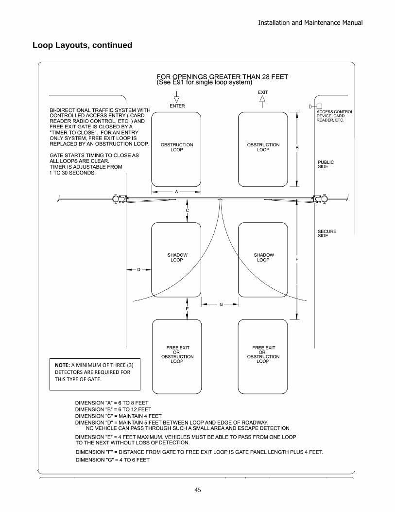
Installation and Maintenance Manual
45
Loop Layouts, continued
NOTE: A MINIMUM OF THREE (3) DETECTORS ARE REQUIRED FOR THIS TYPE OF GATE.

Installation and Maintenance Manual
46
Vehicle Detector Installation Options
The Smart Touch Controller provides a feature rich interface to four different vehicle detector inputs. Standard box type 11 pin (24 Volt DC or 24 Volt AC) vehicle detectors may be connected in the traditional manner.. HySecurity also offers a custom mini detector module that plugs directly into the Smart Touch Control board. Not only is the field installation much faster, but there is also a large performance benefit. The HySecurity HY-5A detector is controlled by the Smart Touch microprocessor to achieve many benefits over common box type detectors* a. Loop frequency is automatically set and monitored
by the Smart Touch Controller b. Cross talk between multiple loops is impossible c. The best operating frequency for each loop is
automatically chosen d. Smart Touch can report the both loop frequency and
call strength on its LCD display e. Smart Touch will report loop malfunctions and store
this data in its EEprom memory f. Most detector or loop faults that could occur are
reported and displayed on the LCD display There are four vehicle detector inputs available both on the main terminal strip and as direct plug in modules. The vehicle detector inputs are for the following functions: 1. Free Exit Loop Detector – “ELD” 2. Outside Obstruction Loop Detector – “OOLD” (this is the outside reversing loop) 3. Inside Obstruction Loop Detector – “IOLD” (this is the inside reversing loop) 4. Shadow Loop Detector – “SLD” (this is for swing gates only) *A combination of HY-5A detectors and standard box detectors is acceptable It is not mandatory to use two separate detectors for inner and outer obstruction detection, however the benefits of using this additional detector are great. Several new features are possible, such as 2nd vehicle intrusion detection, a loitering alert and selectable non-reversing. Multiple obstruction detectors may be mandatory because not more than 200 sq-ft of loop area may be connected to any one detector or the sensitivity becomes inadequate.

Installation and Maintenance Manual
47
HySecurity Hy-5A Vehicle Detector Installation
1. Insert the locking end of each of two 1‖ long white plastic standoffs into the mounting holes on the detector.
2. Plug the detector into the appropriate socket along the right side edge of the Smart Touch Controller board for the detector function that is desired. Be careful to align the six detector pins into the socket correctly, and then snap the standoffs into the holes on the right side of our control enclosure.
3. Route the loop wires through the wire clips provided, and connect the loop leads to the two terminals directly on the detector. Tighten the terminal screws securely.
4. When the power is turned on, the detectors will immediately tune themselves.
5. Once enabled, if the detector module is unplugged, a communications alert [AL10] will be triggered, then if the fault continues, [Err3] ―detector failed‖ is displayed. The operator will also run as if the affected detector is triggered. The [Err3] can only be cleared by pressing the Reset button, which electronically uninstalls the detector. See Detector & Loop Diagnostics.
6. The Smart Touch Controller automatically governs frequency selection of all Hy-5A detector
modules. This simplifies installation and guarantees that there is no cross talk between multiple loops. The frequency can also be manually selected if needed, see the installer menu options.
7. Sensitivity is the only adjustment on the detector itself. Generally sensitivity does not need to be increased unless the loop is large loop or there are multiple loops connected to one detector. Do not exceed more than 200 sq/ft of loop area to one detector. The rotary switch for sensitivity has eight settings, which are as follows: 0 = Low, 1 = Normal, 2 = Medium, 3 = High (0-3 with the boost feature*) 4 = Low, 5 = Normal, 6 = Medium, 7 = High (4-7 no boost feature*) *Boost increases the sensitivity during a call and is very useful for maintaining continuous detection when the signal may become weak, such as semi-trucks.
8. Vehicle detector functions are configurable in the Installer Menu as shown below. Installer Menu Options Default Description
I19 [or 1] OOLD detector function 1 0 = pause closing only, 1 = enable reversing to open I20 [ir 1] IOLD detector function 1 0 = pause closing only, 1 = enable reversing to open I21 [hd 1] SLD- shadow detector function 1 0 = Hold open only, 1 = Hold closed + Hold open I22 [dL 1] Vehicle detector logic 1 1 = std, 2 = Close timer counts even with loops active
The outside and inside Obstruction Loop Detectors ―OOLD‖ or ―IOLD‖ are factory configured to fully re-open the gate as a default setting. In the Installer menu, each detector can individually be set so that when the gate is closing there is only a pause if triggered. To change the IOLD setting, go to the menu item [ir__] and set to 0. For the OOLD, go to the menu item [or__] and set to 0.
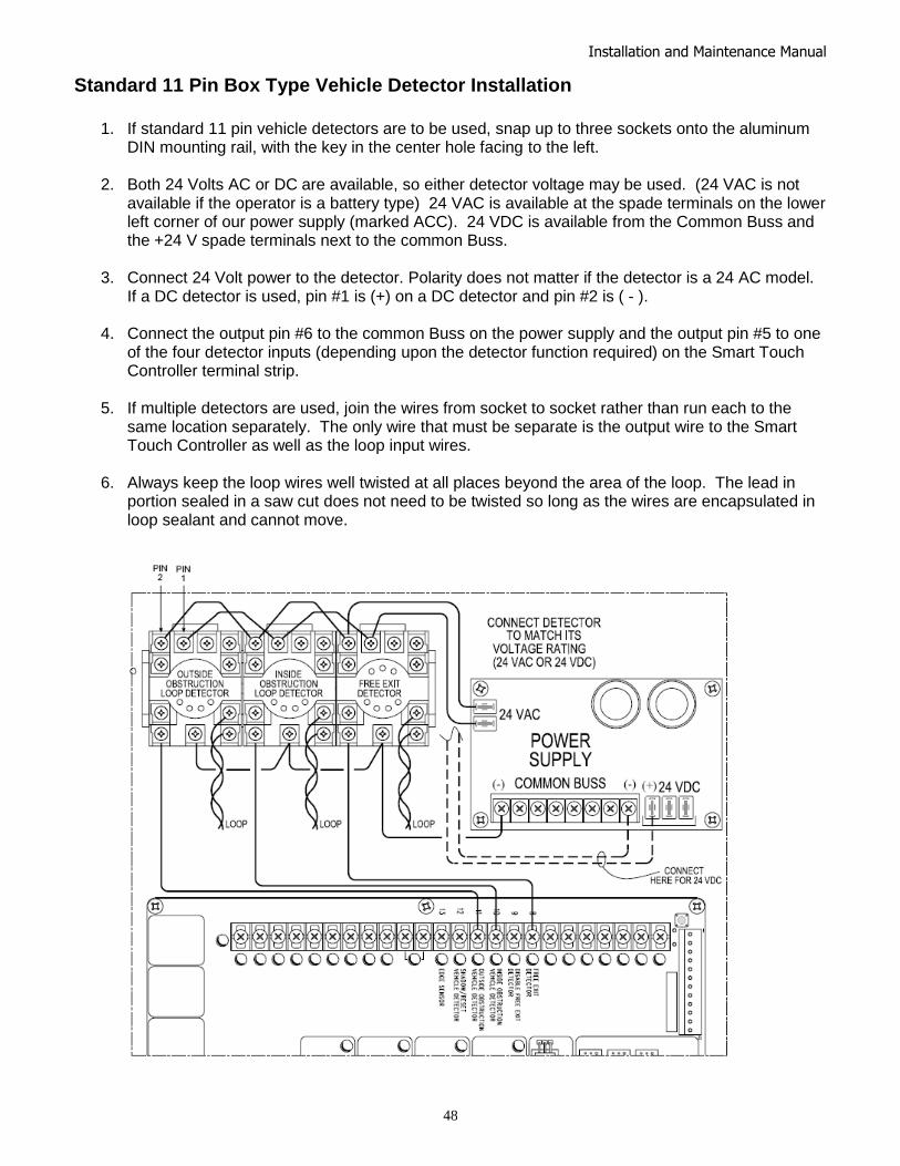
Installation and Maintenance Manual
48
Standard 11 Pin Box Type Vehicle Detector Installation
1. If standard 11 pin vehicle detectors are to be used, snap up to three sockets onto the aluminum
DIN mounting rail, with the key in the center hole facing to the left.
2. Both 24 Volts AC or DC are available, so either detector voltage may be used. (24 VAC is not available if the operator is a battery type) 24 VAC is available at the spade terminals on the lower left corner of our power supply (marked ACC). 24 VDC is available from the Common Buss and the +24 V spade terminals next to the common Buss.
3. Connect 24 Volt power to the detector. Polarity does not matter if the detector is a 24 AC model. If a DC detector is used, pin #1 is (+) on a DC detector and pin #2 is ( - ).
4. Connect the output pin #6 to the common Buss on the power supply and the output pin #5 to one of the four detector inputs (depending upon the detector function required) on the Smart Touch Controller terminal strip.
5. If multiple detectors are used, join the wires from socket to socket rather than run each to the same location separately. The only wire that must be separate is the output wire to the Smart Touch Controller as well as the loop input wires.
6. Always keep the loop wires well twisted at all places beyond the area of the loop. The lead in portion sealed in a saw cut does not need to be twisted so long as the wires are encapsulated in loop sealant and cannot move.

Installation and Maintenance Manual
49
Vehicle Detector & Loop Fault Diagnostics
If HySecurity HY-5A mini detector modules are used, the Smart Touch Controller has ability to store and report detector and loop fault information for performance diagnostics. If The Smart Touch Controller senses a loop or detector problem, the LCD display will flash the abbreviation for the affected detector (ELd – ioLd – ooLd – SLd) then it will flash the appropriate Alert Code [ALE_] to disclose the nature of the problem and the buzzer will chirp.
Loop abnormal freq change alert ALE7 2 chirps/sec every 15 seconds
Loop shorted to ground alert ALE8 2 chirps/sec every 15 seconds
Loop disconnected alert ALE9 2 chirps/sec every 15 seconds
Loop detector active >5 minutes AL12 2 chirps/sec every 15 seconds
Loop detector comm. alert AL10 2 chirps/sec every 15 seconds
Loop detector function alert AL11 2 chirps/sec every 15 seconds
Loop detector failed Err3 3 chirps/sec once per minute
Even if the loop problem self heals, historical data about detector/loop performance and a log of Alerts, Faults and Errors can be retrieved from the Smart Touch Controller by downloading from the RS232 communications port. This requires optional HySecurity software and cables, and a PC computer or a PDA using the Palm OS, in order to read this data. Frequency: Knowing the exact frequency of a loop can be useful as a diagnostic tool and verifying that the loop frequency is stable is also very valuable information. To view the actual loop frequency of a specific vehicle detector, go to the setting for that detector, then change the selection to a flashing 1 and then press the Select button. The display will flash between [F_xx] which are the high digits, then the low digits of the loop frequency counter. For example: [F_05] + [3413] would represent a frequency of 53,413 Hertz. The highest digit will probably be only a single digit because loop frequency is usually a five-digit number, between 20,000 to 80,000 Hertz. Changing the Loop Frequency: HY-5A detectors can never cross talk, but if for any reason, you want to manually change the loop frequency, change the menu selection to a flashing 4 and then press the Select button. Each detector has a choice of four frequencies. To exit, press the Menu button and the controller will perform a reset and tune to the new frequency setting. Call Strength Level: Knowing the strength level of a detector call is valuable because it provides information about how well the loop is actually ―seeing‖ a specific vehicle. For example, it may be useful to check to see if the loop is easily detecting the middle of a high bed semi-truck. The strength of a detector call can be displayed in real time, on a scale of 1-7. As indicated in the table below, when a detector’s menu setting is set to 2, and the Select button is pressed, the LCD display will read [LE_x]. If the call strength is level 4 or less, consider increasing the sensitivity level, by adjusting the rotary switch on the HY-5A detector.
Installer Menu Options Default Description
I28 [ELd0] Test factory ELD 0 0=Run, 1=show freq, 2=show call level 0-7, 3= set Freq 1-4 I29 [iLd0] Test factory IOLD 0 0=Run, 1=show freq, 2=show call level 0-7, 3= set Freq 1-4 I30 [oLd0] Test factory OOLD 0 0=Run, 1=show freq, 2=show call level 0-7, 3= set Freq 1-4 I31 [SLd0] Test factory SLD 0 0=Run, 1=show freq, 2=show call level 0-7, 3= set Freq 1-4
Acronyms: Free Exit Loop = ELd, Outside Obstruction Loop = ooLd, Inside Obstruction Loop = IoLd Shadow Loop Detector = SLd (this is for swing gates only) To return to the installer Menu, press “Program Menu”. Set the selection back to 0 by pressing “Next”, then press “Program Menu” twice to return to Run Mode.
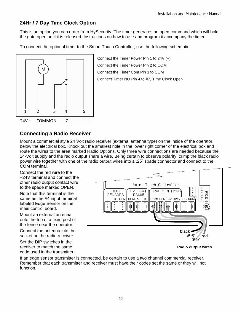
Installation and Maintenance Manual
50
24Hr / 7 Day Time Clock Option
This is an option you can order from HySecurity. The timer generates an open command which will hold the gate open until it is released. Instructions on how to use and program it accompany the timer. To connect the optional timer to the Smart Touch Controller, use the following schematic:
Connect the Timer Power Pin 1 to 24V (+)
Connect the Timer Power Pin 2 to COM
Connect the Timer Com Pin 3 to COM
Connect Timer NO Pin 4 to #7, Time Clock Open
Connecting a Radio Receiver
Mount a commercial style 24 Volt radio receiver (external antenna type) on the inside of the operator, below the electrical box. Knock out the smallest hole in the lower right corner of the electrical box and route the wires to the area marked Radio Options. Only three wire connections are needed because the 24-Volt supply and the radio output share a wire. Being certain to observe polarity, crimp the black radio power wire together with one of the radio output wires into a .25‖ spade connector and connect to the COM terminal.
Connect the red wire to the +24V terminal and connect the other radio output contact wire to the spade marked OPEN.
Note that this terminal is the same as the #4 input terminal labeled Edge Sensor on the main control board.
Mount an external antenna onto the top of a fixed post of the fence near the operator.
Connect the antenna into the socket on the radio receiver.
Set the DIP switches in the receiver to match the same code used in the transmitter.
If an edge sensor transmitter is connected, be certain to use a two channel commercial receiver. Remember that each transmitter and receiver must have their codes set the same or they will not function.

Installation and Maintenance Manual
51
Troubleshooting
Trouble With Gate Movement in General: 1. Review the HRG index arm adjustment and the flow control valve adjustment. 2. Inspect the operator for hydraulic leaks both in the control panel and the base of the operator
post, insure there is sufficient fluid in the reservoir, if not refill it to within 1‖ of the fill plug. 3. During operation listen for unusual sounds and investigate the source.
Electrical Problems in General:
NOTE: The green LED (near terminal #24 on Classic Controllers or near the ―coin‖ battery on New Generation Controllers) is the heartbeat of the processor. This LED should always blink brightly to indicate normal operation.
The Smart Touch Controller reports system malfunctions on its LCD display and the buzzer will emit a series of chirps at defined intervals. Review the matrix of Alerts, Faults and Errors listed in the Troubleshooting chart. To disclose the status of all inputs on the terminal strip, the LED tact button must be pushed. This button is in the upper left corner near the Stop input.
Specific Types of Problems: "I pushed the open and close buttons, but nothing runs."
1. Verify that the line voltage is present and matches the operator voltage + 10%. 2. In three phase applications insure that all three legs of line voltage pass though the power
disconnect switch to the motor contactor, in case one of the lines is dropped somewhere. 3. Verify that control voltage is present at the power supply Common and 24VDC terminals. It may
be necessary to reset the circuit breaker (black button) on the transformer. 4. Verify a jumper wire joins Common to Stop, if an external stop button is not used. 5. Verify there are no Faults or Errors reported on the LCD display. 6. If the motor contactor chatters, voltage drop due to undersized wires is the likely cause. Check
Appendix 9 for maximum allowable length of wiring runs vs. wire size.
"The pump is running but the gate panels don’t move." (Hydraulic pressure is between 0 - 700 PSI on the gauge)
1. If the power is three-phase, verify CCW motor rotation and reverse any two AC lines if needed. 2. Check the level of the hydraulic oil by removing the plug in the reservoir. If necessary, add oil at
this location to within one inch of the filler hole. 3. Unplug the hoses and run the pump, look at the pressure gauge to confirm the system pressure
reaches 1350 PSI. Re-attach the hoses when complete. 4. If relief pressure is not attained, remove the relief valve entirely and depress the plunger at the
nose end with a blunt tool (large Allen wrench) and blow it to remove any debris. Return the valve to the power unit once cleaned.
“Hydraulic pressure is above 700 PSI”
1. Verify that the quick connectors at the hose ends are fully seated when connected. 2. Check the flow control valve, it must not be turned too far clock-wise. See adjustment
instructions.

Installation and Maintenance Manual
52
"The gate panels move in the wrong direction." 1. Check hose connections to verify the correct order red to red and brass to brass. 2. With the system engaged to open, verify that the Open Valve coil develops a strong pull. (This
can be tested by removing the nut retaining the coil and grasping the coil)
"The gate only opens or only closes." 1. If the gate only opens, the directional valve may be stuck and need cleaning or replacement. 2. If the gate only closes, the valve coil is not being energized, or is defective. "I have a bi-parting gate system and the gate panels won’t synchronize.” 1. Air trapped in the hydraulic system can cause slow or jerky movement and prevent the panels
from synchronizing. 2. Refer to General Maintenance and read the instructions for bleeding air from the SwingRiser
hose which is found in the Hydraulic section. “The gate panels move very slowly and seem to shudder throughout gate travel. ” 1. Air trapped in the hydraulic system can cause slow or jerky movement. 2. Refer to General Maintenance and read the instructions for bleeding air from the SwingRiser
hose which is found in the Hydraulic section. GATE SPEED: The speed in which a hydraulic operator moves a gate is determined by the size of the pump and the size of the actuator components. Just like a gear box, this speed is not adjustable. Attempting to slow a gate by changing any valve setting will cause a great deal of inefficiency and heat. If the speed of a gate must be changed, contact your HySecurity distributor. Extremely cold weather is unlikely to seriously affect the speed of the gate, because HySecurity employs a special grade of hydraulic oil that we call UNIFLOW oil, which maintains a very linear viscosity over a broad range of temperatures. Because of this high quality oil and other design considerations, we rate our operators for service in ambient temperatures of –40F degrees to 130F degrees. If the speed of your operator has been affected by cold weather, verify that the gate hardware is not impaired by ice and verify that the reservoir it is filled with UNIFLOW oil. In severe conditions, consider adding a heater.
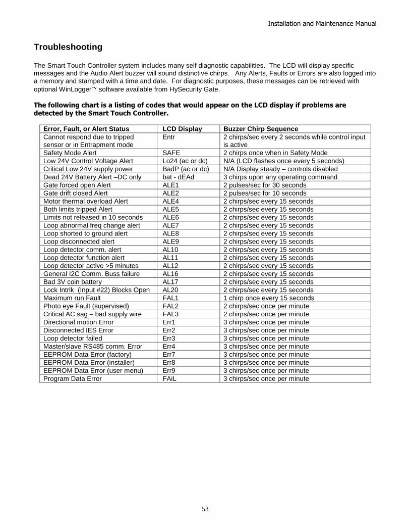
Installation and Maintenance Manual
53
Troubleshooting The Smart Touch Controller system includes many self diagnostic capabilities. The LCD will display specific messages and the Audio Alert buzzer will sound distinctive chirps. Any Alerts, Faults or Errors are also logged into a memory and stamped with a time and date. For diagnostic purposes, these messages can be retrieved with
optional WinLogger software available from HySecurity Gate.
The following chart is a listing of codes that would appear on the LCD display if problems are detected by the Smart Touch Controller.
Error, Fault, or Alert Status LCD Display Buzzer Chirp Sequence
Cannot respond due to tripped sensor or in Entrapment mode
Entr 2 chirps/sec every 2 seconds while control input is active
Safety Mode Alert SAFE 2 chirps once when in Safety Mode
Low 24V Control Voltage Alert Lo24 (ac or dc) N/A (LCD flashes once every 5 seconds)
Critical Low 24V supply power BadP (ac or dc) N/A Display steady – controls disabled
Dead 24V Battery Alert –DC only bat - dEAd 3 chirps upon any operating command
Gate forced open Alert ALE1 2 pulses/sec for 30 seconds
Gate drift closed Alert ALE2 2 pulses/sec for 10 seconds
Motor thermal overload Alert ALE4 2 chirps/sec every 15 seconds
Both limits tripped Alert ALE5 2 chirps/sec every 15 seconds
Limits not released in 10 seconds ALE6 2 chirps/sec every 15 seconds
Loop abnormal freq change alert ALE7 2 chirps/sec every 15 seconds
Loop shorted to ground alert ALE8 2 chirps/sec every 15 seconds
Loop disconnected alert ALE9 2 chirps/sec every 15 seconds
Loop detector comm. alert AL10 2 chirps/sec every 15 seconds
Loop detector function alert AL11 2 chirps/sec every 15 seconds
Loop detector active >5 minutes AL12 2 chirps/sec every 15 seconds
General I2C Comm. Buss failure AL16 2 chirps/sec every 15 seconds
Bad 3V coin battery AL17 2 chirps/sec every 15 seconds
Lock Intrlk (Input #22) Blocks Open AL20 2 chirps/sec every 15 seconds
Maximum run Fault FAL1 1 chirp once every 15 seconds
Photo eye Fault (supervised) FAL2 2 chirps/sec once per minute
Critical AC sag – bad supply wire FAL3 2 chirps/sec once per minute
Directional motion Error Err1 3 chirps/sec once per minute
Disconnected IES Error Err2 3 chirps/sec once per minute
Loop detector failed Err3 3 chirps/sec once per minute
Master/slave RS485 comm. Error Err4 3 chirps/sec once per minute
EEPROM Data Error (factory) Err7 3 chirps/sec once per minute
EEPROM Data Error (installer) Err8 3 chirps/sec once per minute
EEPROM Data Error (user menu) Err9 3 chirps/sec once per minute
Program Data Error FAiL 3 chirps/sec once per minute
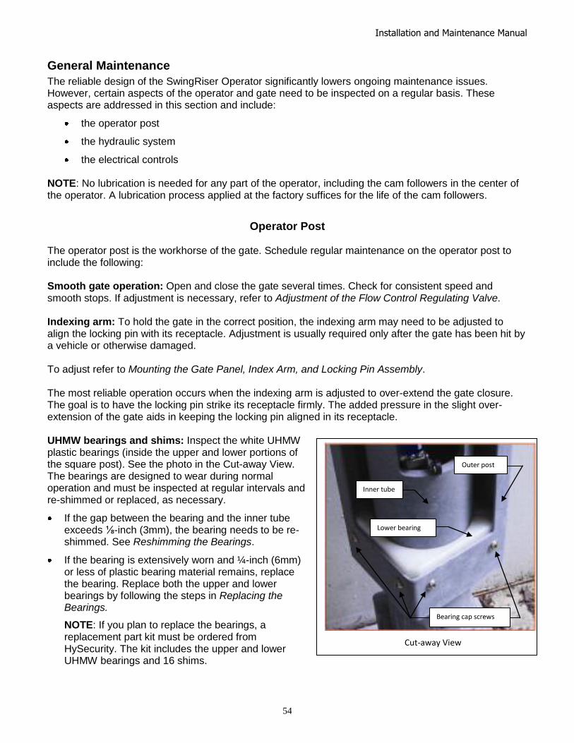
Installation and Maintenance Manual
54
General Maintenance
The reliable design of the SwingRiser Operator significantly lowers ongoing maintenance issues. However, certain aspects of the operator and gate need to be inspected on a regular basis. These aspects are addressed in this section and include:
the operator post
the hydraulic system
the electrical controls NOTE: No lubrication is needed for any part of the operator, including the cam followers in the center of the operator. A lubrication process applied at the factory suffices for the life of the cam followers.
Operator Post The operator post is the workhorse of the gate. Schedule regular maintenance on the operator post to include the following: Smooth gate operation: Open and close the gate several times. Check for consistent speed and smooth stops. If adjustment is necessary, refer to Adjustment of the Flow Control Regulating Valve. Indexing arm: To hold the gate in the correct position, the indexing arm may need to be adjusted to align the locking pin with its receptacle. Adjustment is usually required only after the gate has been hit by a vehicle or otherwise damaged. To adjust refer to Mounting the Gate Panel, Index Arm, and Locking Pin Assembly. The most reliable operation occurs when the indexing arm is adjusted to over-extend the gate closure. The goal is to have the locking pin strike its receptacle firmly. The added pressure in the slight over-extension of the gate aids in keeping the locking pin aligned in its receptacle. UHMW bearings and shims: Inspect the white UHMW plastic bearings (inside the upper and lower portions of the square post). See the photo in the Cut-away View. The bearings are designed to wear during normal operation and must be inspected at regular intervals and re-shimmed or replaced, as necessary.
If the gap between the bearing and the inner tube exceeds ⅛-inch (3mm), the bearing needs to be re-shimmed. See Reshimming the Bearings.
If the bearing is extensively worn and ¼-inch (6mm) or less of plastic bearing material remains, replace the bearing. Replace both the upper and lower bearings by following the steps in Replacing the Bearings.
NOTE: If you plan to replace the bearings, a replacement part kit must be ordered from HySecurity. The kit includes the upper and lower UHMW bearings and 16 shims.
Cut-away View
Inner tube
Lower bearing
Outer post
Bearing cap screws

Installation and Maintenance Manual
55
Reshimming the Bearings
To add shims, you need to order the Shim Kit. It includes four 0.020 and four 0.060 shims. Refer to the HySecurity Price Book for the appropriate part number.
Important aspects to consider when you are shimming bearings:
One half of the bearing is usually worn more than the other. Use different shim thicknesses (0.020 or 0.060) to keep the inner tube centered inside the post.
The weld seam inside the post may prevent the shim from sliding behind the bearing cleanly. If this happens, cut 1-inch out of the middle of a shim and install the two slotted pieces on each side of the weld.
To install shims, take the following steps:
1. To access the upper bearing, close the gate.
2. Turn off the gate operator’s power source. This ensures that the gate will not move while you are installing the shims.
IMPORTANT: Measure the thickness of the material remaining in the upper bearing. Be sure to measure the thinnest portion of the bearing. If the thickness is ¼-inch or less, do not use the shims. Instead, replace both the upper and lower bearings. See Replacing the Bearings.
3. Use a jack screw to lift and block the gate panel. This transfers the weight off the bearings.
4. Loosen, but do NOT remove the four screws in the outer post that secure the worn portion of the bearing. There are four ¼-20 tapped holes adjacent to the screws. Bolts (¼ - 20) may be screwed into these holes to aid in adjusting the gap while shimming.
5. Make a shim packet with 0.060 and 0.020 shims and close the gap tolerance to under 0.020 of an inch. Use a feeler gauge to measure the gap.
NOTE: The weld seam inside the post may prevent the shim from sliding behind the bearing. If this happens, cut 1-inch (25mm) out of the middle of a shim and install the two slotted pieces on each side of the weld.
One inch
cutout
Standard 0.060 Shim
Maintain a consistent gap of 0.020" (0.5mm) around diameter of inner tube.
Add shims to worn bearing and close gap around inner tube.
A B
Weld seam Hinge
¼ - 20 tapped holes
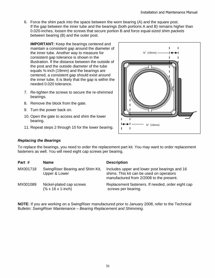
Installation and Maintenance Manual
56
6. Force the shim pack into the space between the worn bearing (A) and the square post. If the gap between the inner tube and the bearings (both portions A and B) remains higher than 0.020-inches, loosen the screws that secure portion B and force equal-sized shim packets between bearing (B) and the outer post.
IMPORTANT: Keep the bearings centered and maintain a consistent gap around the diameter of the inner tube. Another way to measure for consistent gap tolerance is shown in the illustration. If the distance between the outside of the post and the outside diameter of the tube equals ¾-inch (19mm) and the bearings are centered, a consistent gap should exist around the inner tube. It is likely that the gap is within the needed 0.020 tolerance.
7. Re-tighten the screws to secure the re-shimmed bearings.
8. Remove the block from the gate.
9. Turn the power back on.
10. Open the gate to access and shim the lower bearing.
11. Repeat steps 2 through 10 for the lower bearing.
Replacing the Bearings
To replace the bearings, you need to order the replacement part kit. You may want to order replacement fasteners as well. You will need eight cap screws per bearing.
Part # Name Description
MX001718 SwingRiser Bearing and Shim Kit, Includes upper and lower post bearings and 16 Upper & Lower shims. This kit can be used on operators manufactured from 2/2008 to the present.
MX001089 Nickel-plated cap screws Replacement fasteners. If needed, order eight cap (⅜ x 16 x 1-inch) screws per bearing.
NOTE: If you are working on a SwingRiser manufactured prior to January 2008, refer to the Technical Bulletin: SwingRiser Maintenance – Bearing Replacement and Shimming.
¾" (19mm)
¾" (19mm)
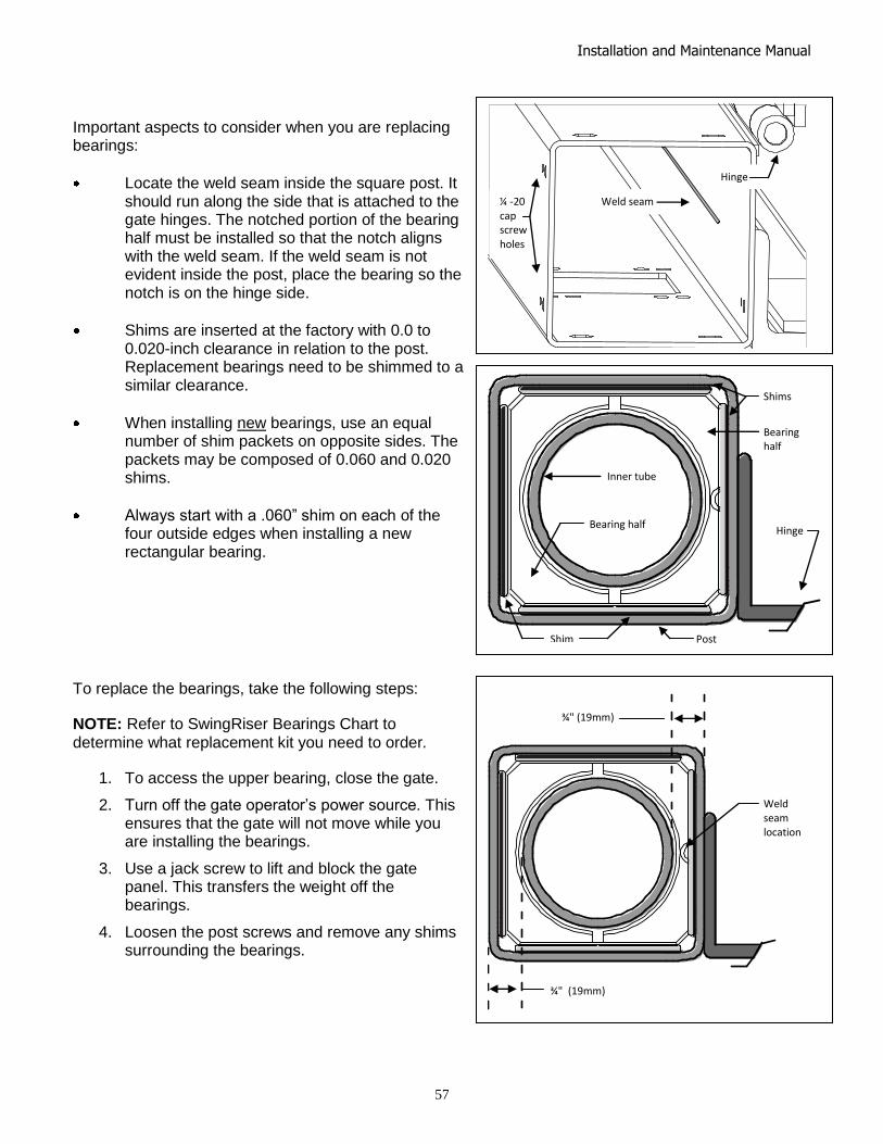
Installation and Maintenance Manual
57
Important aspects to consider when you are replacing bearings:
Locate the weld seam inside the square post. It should run along the side that is attached to the gate hinges. The notched portion of the bearing half must be installed so that the notch aligns with the weld seam. If the weld seam is not evident inside the post, place the bearing so the notch is on the hinge side.
Shims are inserted at the factory with 0.0 to 0.020-inch clearance in relation to the post. Replacement bearings need to be shimmed to a similar clearance.
When installing new bearings, use an equal number of shim packets on opposite sides. The packets may be composed of 0.060 and 0.020 shims.
Always start with a .060‖ shim on each of the four outside edges when installing a new rectangular bearing.
To replace the bearings, take the following steps:
NOTE: Refer to SwingRiser Bearings Chart to determine what replacement kit you need to order.
1. To access the upper bearing, close the gate.
2. Turn off the gate operator’s power source. This ensures that the gate will not move while you are installing the bearings.
3. Use a jack screw to lift and block the gate panel. This transfers the weight off the bearings.
4. Loosen the post screws and remove any shims surrounding the bearings.
¾" (19mm)
Weld seam location
Shims
Bearing half
Hinge
Inner tube
Bearing half
Shim Post
Weld seam ¼ -20 cap screw holes
Hinge
¾" (19mm)

Installation and Maintenance Manual
58
5. Alleviate the possibility of the bearing falling into the post’s interior by using two self-tapping screws and some string. Fasten a separate strand to each screw. Turn the screw into each half of the UHMV plastic bearing until each screw is secure.
6. Remove the four screws in the outer post that hold the worn half of the bearing in place. Pull on the string to remove the bearing from inside the post, and then perform the same step for the other half of the bearing.
7. Use the screw and string technique on the two new bearing halves. Make sure the notch in the bearing is aligned with the post’s weld seam.
8. Replace both bearing halves and use the fasteners removed in step 6 to hold them in place. Do not fully tighten the fasteners until the shims have been properly installed.
9. Shim each side evenly so the distance between the outside edge of the post and the inner tube is equal to ¾-inch (19mm). Make sure the bearing halves are centered in the post and the gap surrounding the inner tube is consistent.
10. Remove the block from the gate.
11. Turn the power back on.
12. Open the gate to access the lower bearing.
13. Repeat steps 2 through 11 to replace the lower bearing.
Hydraulic System Fluid Level: Under normal conditions, hydraulic systems do not consume oil. Before adding any oil, check the system thoroughly for leaks. Remove the bright metal plug in the tank, fill to plug level, then replace plug. We recommend our Uniflow hydraulic oil which is sold in one-gallon containers by our distributors. Refer to the HySecurity Price Book for the appropriate part number. IMPORTANT: Never use brake fluid. It will severely damage the entire hydraulic system. Use of any oil other than Uniflow oil may void the operator warranty.
Look for leaks: Occasionally there may be slight seeping at the fittings after some usage. Tightening of the fittings will usually correct the problem. If the leaking persists, replace "O" rings, fittings or hoses, if required. No further leaks should occur.
Oil Change: A hydraulic system does not foul its oil, unlike a gas engine, so oil changes do not need to be frequent. Oil breakdown caused by heat is the main concern. If the unit is subjected to high use, especially in a warm climate, change the oil more frequently. In general, we recommend draining the reservoir and replacing the oil at five-year intervals. To change the hydraulic oil, remove the reservoir from the pump unit and completely, empty it. Wipe the reservoir can clean and clean any debris from the pickup screen before re-assembling. Refill with new Uniflow hydraulic oil (available from your distributor). To avoid overfilling, fill only through removable plug near the top of the tank. Slowly pour the oil into the tank until the oil is within one inch of the filler port. Replace the plug and wipe up any spilled oil. If any oil is allowed to remain, it will dry to a very sticky and messy consistency. Cold Weather:
1. Check that your reservoir is filled with our Uniflow high performance oil, which is rated to -40 F. 2. Ice can partly or totally jam gate operation. In severe weather inspect the gate for excessive build-ups of snow and Ice.

Installation and Maintenance Manual
59
Bleeding Air from SwingRiser Hoses using the Bleeder Tool Assembly
Air trapped in the hydraulic systems of SwingRiser (HRG) operators can cause slow and/or jerky operation. In SwingRiser Twin (HRG 222) systems (two gate panels operating from a single hydraulic supply), air can prevent the two panels from synchronizing.
If these symptoms are appearing in your operator, take the following steps to bleed the air from the hoses between the hydraulic supply and the operator post.
In SwingRiser Twin systems, both posts must be bled at the same time.
The gate will be inoperative during the bleeding process. If traffic needs to pass, remove the index arm and pivot the gate on the mounting hinges manually.
Tools required: _ 7/32‖ Allen wrench (for cover plate screws) _ Bleeder tool assembly, refer to the HySecurity Price Book for the part
number. A single gate requires one Bleeder tool. A twin gate system requires two Bleeder tools.
_ Two electrical jumper cables
1. Move the gate(s) to the CLOSE position.
2. Turn off power to the hydraulic supply.
3. Check the oil level in the reservoir and fill it to within ½‖ of the fill hole with HySecurity Uniflow hydraulic fluid (The correct part number is found in the HySecurity Price Book.)
4. Remove the cover plate(s) on the stationary base(s) of the post(s).
5. Separate the quick disconnects. Mark the hoses to make note of which hose connects to which connector in the post - one set should be marked with a red wire tie.
6. Attach the feed hoses from the hydraulic supply to the quick disconnects on the bleeder tool. (On Twin post units bleed both posts together with two bleeder tools.)
7. Jumper out the OPEN and CLOSE Limit Switches on the panel mounted terminal strip in the hydraulic cabinet below the keypad.
8. Determine how long you need to run the pump to completely circulate fluid through the entire system. To do this, estimate the total length of hose running from the pump to the post(s) and back (including any hose coiled up in the pump cabinet). Use the chart below to determine how long to run the pump and bleed air from the hoses.
Pump Circulation Time
Operator Type Single Post (¼-inch hose) Double Post (¼-inch hose) Single Post (⅜-inch hose) Double Post (⅜-inch hose)
SwingRiser 14 (HRG-A) 20 seconds/100 hose ft 10 seconds/100 hose ft 40 seconds/100 hose ft 20 seconds/100 hose ft
SwingRiser 19 (HRG-B) 25 seconds/100 hose ft 12 seconds/100 hose ft 50 seconds/100 hose ft 24 seconds/100 hose ft
SwingRiser 30 (HRG-C) 40 seconds/100 hose ft 20 seconds/100 hose ft 80 seconds/100 hose ft 40 seconds/100 hose ft
Example: Double post (two posts), each 50 feet away, have 100+ feet of ¼-inch hose per post equaling a total of 200+ feet. Using the chart for a SwingRiser 19 (HRG-B), the pump will need to run for at least 24 seconds.
Feed hoses from hydraulic supply
Red wire tie
Bleeder tool
Jumpers

Installation and Maintenance Manual
60
9. Turn on the power to the hydraulic supply.
10. Press OPEN or CLOSE to run the motor and pump hydraulic fluid through the hoses. Run the pump for the length of time determined in Step 8.
NOTE: The operator will shut off due to the ―maximum run timer‖ after 1-minute. If needed, press RESET on the keypad and restart the operator (in the same direction) to complete the bleeding process.
When the air has been bled from the hoses, take the following steps:
1. Turn off the power.
2. Remove the Open/Close limit switch jumpers in the hydraulic supply cabinet.
3. Check the fluid level in the reservoir and refill to ½‖ below the fill port if low.
4. Disconnect the bleeder tool assembly(s) and reconnect all hoses in the post(s). Be sure the color-coded socket and plug are matched and connected properly.
5. Reinstall the cover plate over the hydraulic connections.
6. If the index arm was disconnected, re-attach it now. Any spaces between the arm ends and the brackets on the post and gate should be completely filled with washers and the attaching bolts tightened to a minimum of 75 ft-lbs.
7. Turn on the power.
8. Test the gate to make sure it opens and closes properly, and then place into service.
NOTE: The above process will remove the air from the hoses, but may leave some air trapped in the cylinder(s). If lagging or sluggish operation persists, cycle the gates several times forcing the air from the cylinder(s) into the hoses, then, repeat the bleeding process above.
Electrical Controls
Before servicing, turn off power disconnect switch
No routine maintenance is needed for the electrical system or controls. If the environment is very sandy or dusty, or has many insects, make sure to seal all holes in the electrical enclosure. Blow the dust out of the electric panel with compressed air. A qualified technician may troubleshoot with the aid of the troubleshooting guide in this appendix. If it is necessary to call a distributor for assistance, be sure to have your model and serial number ready. Other helpful information would include the name of the job, approximate date of installation, and the service record of the operator, especially any work that has been done recently.
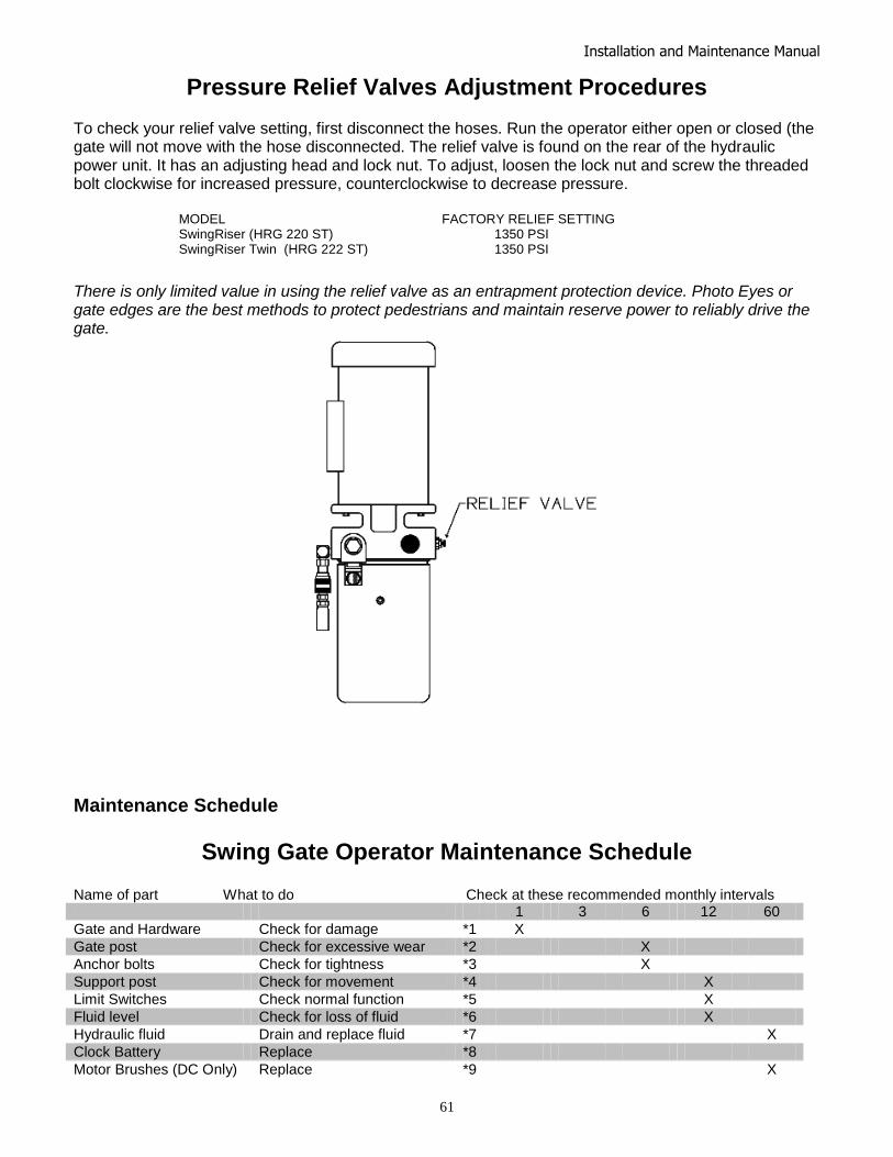
Installation and Maintenance Manual
61
Pressure Relief Valves Adjustment Procedures To check your relief valve setting, first disconnect the hoses. Run the operator either open or closed (the gate will not move with the hose disconnected. The relief valve is found on the rear of the hydraulic power unit. It has an adjusting head and lock nut. To adjust, loosen the lock nut and screw the threaded bolt clockwise for increased pressure, counterclockwise to decrease pressure.
MODEL FACTORY RELIEF SETTING SwingRiser (HRG 220 ST) 1350 PSI SwingRiser Twin (HRG 222 ST) 1350 PSI
There is only limited value in using the relief valve as an entrapment protection device. Photo Eyes or gate edges are the best methods to protect pedestrians and maintain reserve power to reliably drive the gate.
Maintenance Schedule
Swing Gate Operator Maintenance Schedule Name of part What to do Check at these recommended monthly intervals 1 3 6 12 60
Gate and Hardware Check for damage *1 X
Gate post Check for excessive wear *2 X
Anchor bolts Check for tightness *3 X
Support post Check for movement *4 X
Limit Switches Check normal function *5 X
Fluid level Check for loss of fluid *6 X
Hydraulic fluid Drain and replace fluid *7 X
Clock Battery Replace *8
Motor Brushes (DC Only) Replace *9 X

Installation and Maintenance Manual
62
Special Notes: *1 Your gate will usually require more maintenance than the HySecurity operator that is moving the gate. Damaged or warped gate panels are signs that a vehicle may have hit the gate. Verify that the actuator post is not also damaged. *2 Normally, with correct operator speed, the actuator post should need very little attention. If your gate panel is very heavy or in high wind area locations the six-month inspection should include a look into the post itself. Check the mounting base inspection cover you should find it clean. If there is any sign that the brass bushings have deteriorated or there is wear in the UHMW bearings at the top and bottom of the square post (a gap of more than 3/8‖around the inner tube) further inspection is appropriate. *3 The anchor bolts at the base of the post should remain tight. If the bolts are loose, there may be an issue where the supporting post has issues or may be out of plum or the gate may be have been forced. *4 The support post is the most critical support structure. If there is a problem with the support post, the gate panel will sag and the mounting base will be shouldering too much of the load. Correct this problem immediately. *5 During this inspection you will need to open the limit switch cover, and check that the limit switches are clean, tight and that the lever arms moves freely without feeling gummy. (The open limit switch is on the left, close limit on the right) *6 The oil level should remain approximately one inch below the filler hole. See maintenance instructions for oil filling. Loss of fluid is not normal and indicates a leak that must be located and repaired. If additional fluid is required, use ―Uniflow‖ fluid. For the appropriate part number, refer to the HySecurity Price Book. *7 Oil breakdown is caused by heat. If the operator subjected to high use and/or high temperatures change the oil more frequently. *8 Replace the Smart Touch Controller battery with DL 2025 / DL 2032 or CR 2025 / CR 2032. *9 DC Operators use DC motors with carbon brushes which wear in normal operation. Worn brushes can damage the DC motor. Under severe conditions HySecurity recommends that brushes be checked after 2 years and the replacement interval be adjusted as necessary.

Installation and Maintenance Manual
63
IMPORTANT SPECIAL NOTES REGARDING
D.C. POWERED GATE OPERATORS
The on/off switch on the electric control panel of the drive unit does not disable all DC power to the operator, even if the AC power has been disabled at its source. The large rotary switch in the DC power supply enclosure must be actuated off to insure disconnect of all DC power to the drive unit. The disconnect in the power supply must be off if the AC source power will be absent for more than one week. This avoids slowly discharging the batteries into the battery charger. Batteries will self-discharge and therefore the DC power supply must not be stored for a period longer than 6 months without recharging the batteries. Batteries contain sulfuric acid. If batteries are dropped or damaged, be cautious not to get acid in the eyes, on skin, or on clothing. Be certain to observe polarity when connecting the batteries, or adding accessories. Reversed polarity may result in a non-functional operator or possibly damage a component. Red is (+) positive, and black is (-) negative. Since the electrical current under load is very high, be certain that the minimum conductor size, specified in the installation instructions, is used for the connection between the battery pack and the operator. If the battery pack is more than 20 feet from the operator, use a larger wire size, according to the distance between the operator and the batteries. If shorted, batteries will generate a very high current. Observe special care when connecting the cables to the batteries that the polarity is correct. The batteries are connected in a series circuit: join the positive (+) terminal from one battery to the negative (-) terminal of the next battery. Since the operator is intended to run on batteries, control of the load is important. Easier moving gates will drain less energy from the battery, preserving capacity for more cycles during a power failure. HySecurity uses a permanently sealed type battery, which needs no maintenance over its life span. A low voltage-sensing circuit protects the batteries from damage which could be caused by over-discharge. The charger automatically regulates its output to allow high output when the battery is partially discharged. The output will automatically be reduced to zero as the batteries become fully charged. Batteries have a finite life. As the batteries age, they will lose some of their capacity to store energy. If the total amount of back up capacity is critical, plan to replace the batteries after 5 years of use. Properly dispose of or recycle used batteries. Batteries are rated to perform to capacity at a temperature of 77 degrees Fahrenheit. Below 77 degrees, the "amp hour" capacity is temporarily reduced. For example, at freezing, the capacity is 75%, at 10 degrees Fahrenheit, the capacity is 50%. HySecurity insulates the battery pack to guard against this loss. Do not remove any insulation or the performance of the system may be adversely affected. Batteries can be damaged by excessive heat, which may shorten their life span. Therefore, do not paint the battery enclosure a dark color that could cause it to absorb a lot of heat from sunlight. DC Motors contain carbon brushes which wear over time and must be replaced. Failure to replace the brushes will result in damage to the DC motor. Brushes should be replaced every 5 years, or sooner in high use and/or severe duty installations.
Installation and Maintenance Manual
64
Wiring and Control Configuration for DC Operators
If this installation is a 24-Volt DC battery type gate operator, there are a few additional steps that must be completed before the system can be functional. Review the installation instructions below and the Battery Connection Diagram. Be certain the DC power disconnect switch is turned off before making any connections.
1. Connect the heavy gauge wires between the battery enclosure and the gate operator as follows: Be certain to observe polarity carefully!
a. From the battery enclosure the (+) lead connects to the lug on the large rotary power
disconnect switch. The (-) lead connects to the lug on the circuit breaker. At the gate operator the (+) lead connects directly to the lug on the top of the DC electric motor. The (-) lead connects to the bottom lug on the contactor mounted alongside the DC motor. All lug connections must be tightened very securely since they pass high current to the gate operator.
2. Connect two separate 14-gauge circuits between the battery enclosure and the gate operator.
One circuit provides the 24 VDC to the gate operator controls and the second circuit is required so that the Smart Touch Controller knows that the battery charger is operating normally on AC power. Be certain to observe polarity carefully!
a. Connect four wires to the terminal strip in the battery supply labeled: (+)24, (-)24, COM,
#21. The 24 Volt (+) and (-) terminals connect to the red (+) and black (-) wires at the on/off power switch in the gate operator.
b. The COM and #21 terminals connect to the Common Buss and to terminal #21 (Charger AC power loss) on the Smart Touch Controller.
3. The Smart Touch Controller User Menu (U4) provides four optional system configurations for 24-Volt DC battery type gate operators. Since this is an uninterruptible power supply system, the installer must decide, depending upon customer preference, what is to happen when the AC line power fails. The User Relays will operate to less than 18VDC. There are four functional choices provided in the User Menu, item [AP__].
Setting 0 (Type A): The operator functions normally until the batteries drop to 20 Volts, then auto open and lock until the battery voltage recovers to 23.5 Volts. The gate can still be manually closed only by a Close Pushbutton or an Emergency Close input and will then re-open by any open command until the battery voltage drops to 17 Volts at which time the gate is absolutely locked open.
Setting 1 (Type B): The operator functions normally until the batteries drop to 20 Volts, then auto close and lock closed until battery voltage recovers to 23.5 Volts. The gate can only be opened by a special combination of a Stop Pushbutton input, then within 1 second, an Open Pushbutton input. The Fire Department open input can open the gate without the special PBS enabling pre-input. The gate can be re-closed only by Close Pushbutton and the Emergency Close inputs. When the battery voltage drops to 17 Volts, the gate completes its final cycle and stays in the full open or full closed position, depending upon which cycle was last. Setting 2 (Type C): The operator automatically opens five seconds after loss of AC power and locks open, until AC power is restored. The gate can still be manually closed only by a Close Pushbutton or an Emergency Close input and will then re-open by any open command until the battery voltage drops to 17 Volts at which time the gate is absolutely locked open. Setting 3 (Type D): Same as type C, except the operator initially does nothing after loss of AC power, but then locks open after the next open command of any type.

Installation and Maintenance Manual
65
Battery Connection Diagram
Connect six wires to the gate operator as shown. Install batteries as show, observing polarity:
Four 14 gauge wires to the control circuit. Always connect red wires to (+) and black wires to (-). The exception is
Connect from lug terminals to DC motor: the jumper wire which connects the two batteries.
Two 6 gauge minimum for 1hp operators
Two 2 gauge minimum for 2hp operators

Installation and Maintenance Manual
66
APPENDIX
For ½-hp through 5-hp motors
Supplying a gate operator with the right electrical service is crucial to the way the performance of the operator the life of its electrical components. If the wire size used is too small, the voltage loss—especially during motor starting—will prevent the motor from attaining its rated horsepower. The percent of horsepower lost is far greater than the percentage of the voltage loss. A voltage loss could also cause the control components to chatter while the motor is starting, substantially reducing their life due to the resultant arcing. There is no way to restore the lost performance resulting from undersized wires, except to replace them; therefore it is much more economical to choose a sufficient wire size at the initial installation. The tables on the following page are based on copper wire and allow for a 5% voltage drop. The ampere values shown are the service factor ampere rating (maximum full load at continuous duty) of the motor. Always connect electrical power and ground the operator in accordance with the National Electrical Code, article’s 430 and 250 plus other local codes that may apply. The maximum distance shown is from the gate operator to the power source; assuming that source power is from a panel box with adequate capacity to support the addition of this motor load. The values are for one operator, with no other loads applied to the branch circuit. Avoid placing more than one gate operator to a circuit, but if you must be certain to reduce the maximum allowed distance by half.
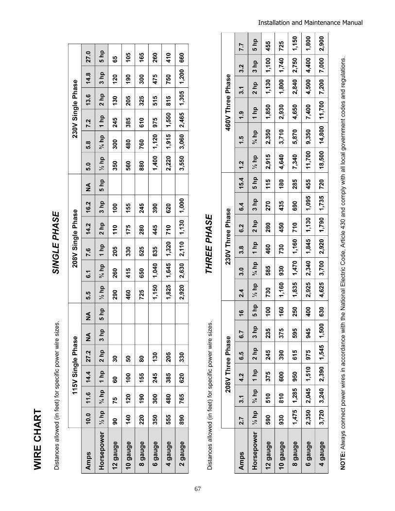
Installation and Maintenance Manual
67
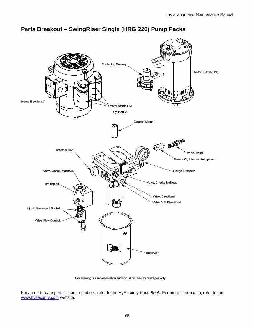
Installation and Maintenance Manual
68
Parts Breakout – SwingRiser Single (HRG 220) Pump Packs
For an up-to-date parts list and numbers, refer to the HySecurity Price Book. For more information, refer to the www.hysecurity.com website.
(1Ø ONLY)

Installation and Maintenance Manual
69
Parts Breakout – SwingRiser Twin (HRG 222) Pump Packs
For an up-to-date parts list and numbers, refer to the HySecurity Price Book. For more information, refer to the www.hysecurity.com website.
(1Ø ONLY)
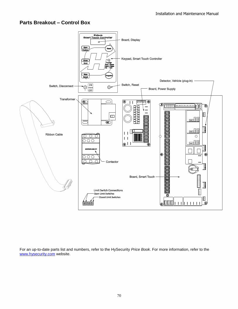
Installation and Maintenance Manual
70
Parts Breakout – Control Box
For an up-to-date parts list and numbers, refer to the HySecurity Price Book. For more information, refer to the www.hysecurity.com website.
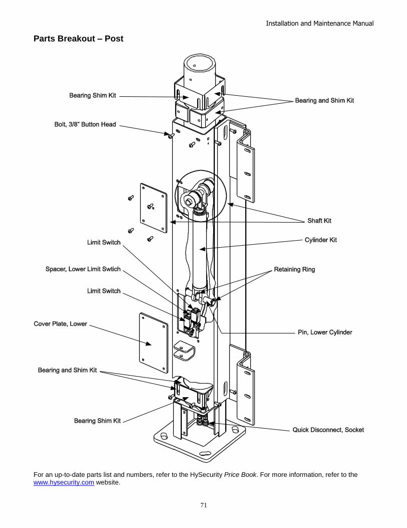
Installation and Maintenance Manual
71
Parts Breakout – Post
For an up-to-date parts list and numbers, refer to the HySecurity Price Book. For more information, refer to the www.hysecurity.com website.
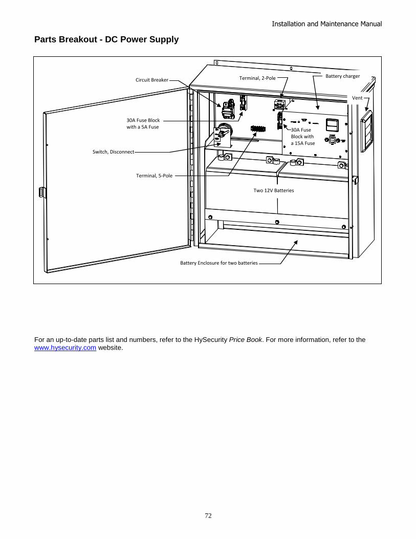
Installation and Maintenance Manual
72
Parts Breakout - DC Power Supply
For an up-to-date parts list and numbers, refer to the HySecurity Price Book. For more information, refer to the www.hysecurity.com website.
Battery charger
Two 12V Batteries
Circuit Breaker
Switch, Disconnect
Terminal, 5-Pole
30A Fuse Block with a 5A Fuse
30A Fuse Block with a 15A Fuse
Terminal, 2-Pole
Vent
Battery Enclosure for two batteries

Installation and Maintenance Manual
73
Smart Touch Controller Connections

Installation and Maintenance Manual
74

Installation and Maintenance Manual
75
1. Warranty. Hy-Security Gate, Inc. (―HySecurity‖) warrants that at the time of sale each of its products will, in all material respects, conform to its then applicable specification and will be free from defects in material and manufacture. This warranty does not extend to items listed as ―accessories‖ in HySecurity’s price list, when those items carry another manufacturer’s name plate and they are not a part of the base model. HySecurity disclaims all warranties for such accessory components, which carry only the original warranty, if any, of their original manufacturer. HySecurity hereby assigns its rights under such manufacturer warranties—to the extent that such rights are assignable—to Buyer.
The following additional durational warranties apply to HySecurity’s products. The term of these additional warranties is determined by whether (1) the product is purchased through an authorized HySecurity distributor and (2) whether a timely and complete warranty registration is submitted to HySecurity. It is therefore important that you register your product with HySecurity within the 60 day period described below.
1(a) Five Year / Seven Year Warranty Items (Registered Gate Operators Purchased from Authorized Distributors)
For any gate operator product that is purchased from an authorized HySecurity distributor (this excludes product purchased through internet resellers or any distributor not authorized by HySecurity), if the online Warranty registration is completed at www.hysecurity.com/warranty within 60 days of the date of purchase by the dealer/installer or if the warranty registration form sent with every HySecurity gate operator is completely filled out and returned to HySecurity within the same 60-day period, the following Warranty terms will apply: HySecurity will warrant that the product will remain serviceable for the following periods:
a. Hydraulic Gate Operators: Five Years or 500,000 gate cycles (whichever occurs first) after the date of installation, or
b. Electromechanical operators: Five Years after the date of installation—unless installed in a single family residential application, in which case the warranty term shall be Seven Years after the date the product is shipped from HySecurity; provided that the Five Year warranty period will not extend beyond Seven Years from the date that the product was shipped from HySecurity. This warranty does not apply to the components described below, which have the shorter warranty period indicated:
c. Hydraulic Gate Operator Drive Wheels: Two Years from date of installation.
d. Batteries used in all D.C. operators: One Year from date of shipment from HySecurity.
e. Items subject to normal wear including, but not limited to, chains, belts, idler wheels, sprockets, fuses and motor brushes: One Year from date of installation.
1(b) One Year Warranty Items (Operators Not Purchased from an Authorized Distributor or Registered within 60 Days)
For any gate operator product that is not purchased from an authorized HySecurity distributor or for which the online Warranty registration or warranty registration form sent with every HySecurity operator was not filled out completely or not returned to HySecurity within 60 days of the date of purchase by the dealer/installer, the following One-Year Warranty will apply to that product: HySecurity warrants that the product will remain serviceable for the following periods, which begin on the date that the product was shipped from HySecurity:
a. All Gate Operators: One Year or 100,000 gate cycles whichever comes first.
b. Hydraulic Gate Operator Drive Wheels: One Year
1(c) Replacement Parts
HySecurity warrants that replacement parts (whether new or reconditioned) will remain serviceable for One Year from the date that the product was shipped from HySecurity.
1(d) Limitations and Exclusions Applicable to Each of the Preceding Warranties
The preceding warranties shall not apply to equipment that has been (1) installed or maintained improperly or contrary to instructions; (2) subjected to negligence, accident, vandalism, or damaged by severe weather, wind, flood, fire, or war; or (3) damaged through improper operation, maintenance, storage or abnormal or extraordinary use or abuse. Any modification made to products will void the warranty unless the modifications are approved in writing by HySecurity, in advance of the change (this exclusion does not apply to normal installation of approved accessories and/or protective devices or sensors).
THESE ARE THE ONLY WARRANTIES GIVEN BY HYSECURITY AND ARE IN PLACE OF ALL OTHERS.
These warranties extend to HySecurity’s Distributors, to the Dealer/Installer, and to the First User of the product following installation. They do not extend to subsequent purchasers. Dealer/Installers or First Users may receive a replacement HySecurity Warranty form by calling HySecurity at 800-321-9947.
2. Exclusion of Other Warranties.
The warranties contained in Section 1 are the exclusive warranties given by HySecurity and supersede any prior, contrary or additional representations, whether oral or written. Any prior or extrinsic representations or agreements are discharged or nullified. HYSECURITY HEREBY DISCLAIMS AND EXCLUDES ALL OTHER WARRANTIES—WHETHER EXPRESS, IMPLIED, OR STATUTORY—INCLUDING ANY WARRANTY OF MERCHANTABILITY, ANY WARRANTY OF FITNESS FOR A PARTICULAR PURPOSE, AND ANY IMPLIED WARRANTIES OTHERWISE ARISING FROM COURSE OF DEALING, COURSE OF PERFORMANCE, OR USAGE OF TRADE.
3. Buyer's Exclusive Remedies for Any Nonconformity.
If a HySecurity product fails to conform to the warranties in Section 1, Buyer must notify and order replacement parts from the Distributor through which the product was purchased within a reasonable time and in no event more than thirty (30) days after the discovery of the nonconformity. HySecurity will investigate and, in the event of a breach, will provide, within a reasonable period of time, one of the following: (1) repair or replacement of any nonconforming products or components or (2) refund of the price upon return of the nonconforming items. Replacement goods will conform to this warranty for the unexpired duration of the warranty period for the original, nonconforming product. HySecurity reserves the right to supply used or reconditioned material for all warranty claims. This warranty does not cover or extend to any incidental expenses, including labor, shipping, travel time or standby time, that are incurred for inspection or replacement of any nonconforming items. As a condition of warranty coverage, warranty claims must be submitted in accordance with the following paragraph. THE REMEDY SELECTED BY HYSECURITY IN ACCORDANCE WITH THIS PARAGRAPH SHALL BE THE EXCLUSIVE AND SOLE REMEDY OF BUYER FOR ANY BREACH OF WARRANTY. IN NO EVENT SHALL HYSECURITY BE OBLIGATED TO INDEMNIFY BUYER FOR ANY BREACH OF WARRANTY.
For warranty coverage, you must follow the procedures described on HySecurity’s form, ―RMA Procedures.‖ A current version of the form is available from HySecurity.
4. Exclusion of Consequential and Incidental Damages.
IN NO EVENT SHALL HYSECURITY BE LIABLE FOR ANY INCIDENTAL, SPECIAL, INDIRECT, OR CONSEQUENTIAL DAMAGES, WHETHER RESULTING FROM NONDELIVERY OR FROM THE USE, MISUSE, OR INABILITY TO USE THE PRODUCT OR FROM DEFECTS IN THE PRODUCT OR FROM HYSECURITY’S OWN NEGLIGENCE OR OTHER TORT. This exclusion applies regardless of whether such damages are sought for breach of warranty, breach of contract, negligence, or strict liability in tort or under any other legal theory. This exclusion does not apply to claims for bodily injury or death.
5. Severability.
If any provision of this warranty is found to be invalid or unenforceable, then the remainder shall have full force and effect, and the invalid provision shall be partially enforced to the maximum extent permitted by law to effectuate the purpose of the agreement.
6. Applicable Law.
This Warranty will be interpreted, construed, and enforced in all respects in accordance with the laws of the State of Washington, without reference to its choice of law principles. The U.N. Convention on Contracts for the International Sale of Goods will not apply to this Warranty.

Installation and Maintenance Manual
76
Copyright Notice
© Copyright 2010 by HySecurity Gate Inc.
All rights reserved. No part of this manual may be reproduced by any means (photocopier, electronic, or mechanical), without the express written
permission of HySecurity Gate Inc. Federal Copyright law prohibits the reproduction, distribution, or public display of copyrighted materials without
the express written permission of the copyright owner, unless fair use or other exemption under copyright law applies. Additionally, HySecurity Gate
Inc. makes no representations or warranty with respect to this manual. We also reserve the right to make changes in the products described without
notice and without any obligation to notify any persons of any such revision or change.
Trademarks
SwingSmart, Smart DC Controller, S.T.A.R.T. and the HySecurity logo are trademarks or registered trademarks of HySecurity Gate, Inc.
Publication Information
Published in the United States of America. D0121 Revision D