Embed Size (px)
Citation preview

Manual PN 9610-05-1001-18 Firmware Version 5.0
Installation and Operations Manual for Stand-alone
F/T Sensor Systems
Intelligent Multi-axis Force/Torque Sensor System
Pinnacle Park, 1031 Goodworth Drive, Apex, NC 27502 USA ISO 9001 Registered Email: [email protected] www.ati-ia.com Tel: +1.919.772.0115 Fax: +1.919.772.8259

Manual PN 9610-05-1001-17Firmware Version 5.0
Installation and OperationsManual for Stand-alone
F/T Sensor Systems
Intelligent Multi-axisForce/Torque Sensor System
Pinnacle Park, 1031 Goodworth Drive, Apex, NC 27502 USAISO 9001 RegisteredEmail: [email protected] www.ati-ia.comTel: +1.919.772.0115 Fax: +1.919.772.8259
ii
ATI Industrial Automation
Information contained in this document is the property of ATI Industrial Automation, Inc. andshall not be reproduced in whole or in part without prior written approval of ATI IndustrialAutomation, Inc. The information herein is subject to change without notice and should not beconstrued as a commitment on ATI Industrial Automation, Inc. This manual is periodicallyrevised to reflect and incorporate changes made to the F/T system.
ATI Industrial Automation, Inc. assumes no responsibility for any errors or omissions in thisdocument. Users' critical evaluation is welcome to assist in the preparation of futuredocumentation (see the “What Do You Think” section at the end of this manual).
Copyright © July 2001 by ATI Industrial Automation, Inc., Apex, North Carolina. All RightsReserved.
Published in the USA.First printing June 1991.
FCC Compliance - Class BThis device complies with Part 15 of the FCC Rules. Operation is subject to the following twoconditions: (1) this device may not cause harmful interference, and (2) this device must acceptany interference received, including interference that may cause undesired operation.
CE ComplianceThis device complies with EMC Directive 89/336/EEC and FCC Title 47 CFR, Part 15 Subpart Band conforms to the following standards: ANSI C63.4:1992, CISPR 22: 1993, Amt. 1 ,2, EN 61000-4-2: 1995, EN 61000-4-3:1997, EN 61000-4-4:1995, EN 61000-4-5:1995, EN 61000-4-6:1996, EN 61000-4-8:1994, EN 61000-4-11:1995.
ECC ComplianceThis device complies with Council Directive: 73/23/ECC and conforms to Cenelec Standard EN60101-1: 1993.
In consideration that ATI Industrial Automation, Inc. (ATI) products are intended for use withrobotic and/or automated machines, ATI does not recommend the use of its products forapplications wherein failure or malfunction of a ATI component or system threatens life or makesinjury probable. Anyone who uses or incorporates ATI components within any potentially lifethreatening system must obtain ATI’s prior consent based upon assurance to ATI that amalfunction of ATI’s component does not pose direct or indirect threat of injury or death, and(even if such consent is given) shall indemnify ATI from any claim, loss, liability, and relatedexpenses arising from any injury or death resulting from use of ATI components.

iii
ATI Industrial Automation
Aside...
Please read the manual before calling customer service. Before calling have the followinginformation available:1. Serial number.2. Transducer model (e.g., Nano17, Gamma, Theta, etc.).3. Calibration (e.g., US-15-50, SI-65-6, etc.)4. Accurate and complete description of the question or problem.5. Software revision. This is output in the power-on header message and can also be
found on the microprocessor inside the F/T stand-alone controller.
If possible be near the F/T system when calling.

iv
ATI Industrial Automation
TABLE OF CONTENTS
Section Page
Getting Started1.1 INTRODUCTION ...................................................................................................1-21.2 UNPACKING...........................................................................................................1-21.3 SYSTEM COMPONENTS DESCRIPTION .........................................................1-3
Transducer............................................................................................................1-3Transducer Cable..................................................................................................1-4F/T Controller........................................................................................................1-4F/T Software ..........................................................................................................1-4Interface Plates.....................................................................................................1-5Optional Analog Output........................................................................................1-5
1.4 CONNECTING THE SYSTEM COMPONENTS ................................................1-5Transducer Cable Interfacing ..............................................................................1-5Serial Port Interfacing ..........................................................................................1-7Using Hyper Terminal in Windows for Serial Communications ........................1-8Power Cord Connection........................................................................................1-9
1.5 TESTING THE F/T SYSTEM.................................................................................1-9Turning On the F/T Controller.............................................................................1-9Warm Start, ^W....................................................................................................1-10Reset Button.........................................................................................................1-10Output ASCII Force Vector (Serial Port) and Biasing........................................1-10Using the Zip Macro Start-up, ZC........................................................................1-11
Installation2.1 INTRODUCTION ...................................................................................................2-22.2 ROUTING THE TRANSDUCER CABLE............................................................2-22.3 MOUNTING THE TRANSDUCER ......................................................................2-3
Transducer Mounting Method I, Standard Mounting Adaptor..........................2-3Transducer Mounting Method II, Mounting Ring-plug Adaptor.......................2-4Transducer Mounting Method III, User-designed Interface .............................2-5
2.4 MOUNTING YOUR TOOL....................................................................................2-6Tool Mounting Method I, Standard Tool Adaptor..............................................2-6Tool Mounting Method II, Optional Tool Ring-plug Adaptor............................2-6

v
ATI Industrial Automation
How It Works3.1 INTRODUCTION ...................................................................................................3-23.2 ELECTRONIC HARDWARE................................................................................3-23.3 SOFTWARE OUTLINE..........................................................................................3-33.4 MECHANICAL DESCRIPTION...........................................................................3-3
Software4.1 COMMAND OVERVIEW AND PROTOCOL.....................................................4-24.2 COMMUNICATION SETUP COMMANDS.......................................................4-5
Sensor Error..........................................................................................................4-5Communication Data Mode (CD A, CD B).........................................................4-5Communication Data Checksum (CD E, CD U)..................................................4-6Communicate Data Type (CD D, CD H, CD R).................................................4-7Communication Output Selection (CA b, CP a)...................................................4-8Other Communication Setup Commands (CF d, CL b, CV h) ............................4-9
4.3 QUERY COMMANDS...........................................................................................4-11Query Data Request Commands (QR, ^T, ^N, QS) ..........................................4-11Query Calibration Matrix (QC) ...........................................................................4-12Query F/T Peaks (QP) ..........................................................................................4-12
4.4 SENSOR COMMANDS.........................................................................................4-13Sensor Biasing (SB, SU, SZ) ................................................................................4-13Optional Sensor Temperature Compensation (ST b) ..........................................4-14Sensor Peaks (SP b, SC).......................................................................................4-16Sensor Error Message (SM b).............................................................................4-17Sensor Sampling Frequency (SF d) ......................................................................4-17Sensor Averaging (SA d) ......................................................................................4-18
4.5 DISCRETE I/O COMMANDS ..............................................................................4-18I/O Verification (ID, OD h) ..................................................................................4-18Force Monitoring Commands (MC s, MD d, ML) .............................................4-20
4.6 TOOL FRAME COMMANDS ...............................................................................4-22Tool Frame Selection, Listing and Deleting (TF d, TL, TD d) ...........................4-23Tool Frame Construction (TC d, s, x, y, z, µ, ß, ø) ...............................................4-24
4.7 OTHER F/T COMMANDS....................................................................................4-25Zip Macro Create Start-up Buffer (ZC 0, "s")....................................................4-25Warm Start (^W) ..................................................................................................4-26Filter Clock (FC d) ................................................................................................4-26XON and XOFF (^Q, ^S) .....................................................................................4-26Store and Reload Run Memory (RS, RL)...........................................................4-27

vi
ATI Industrial Automation
Serial and Discrete I/O5.1 SERIAL AND DISCRETE I/O PIN ASSIGNMENTS .........................................5-2
Serial I/O Pin-out ..................................................................................................5-2Discrete I/O Pin-out ..............................................................................................5-3
5.2 SERIAL I/O DESCRIPTION .................................................................................5-45.3 DISCRETE I/O DESCRIPTION............................................................................5-4
Typical Input and Output Connections ................................................................5-4Monitor Conditions ...............................................................................................5-4Discrete I/O Timing Diagram...............................................................................5-6Health Line............................................................................................................5-7Bias Line ...............................................................................................................5-8
5.4 SERIAL AND DISCRETE I/O ELECTRICAL CHARACTERISTICS..............5-8Serial I/O Electrical Characteristics ....................................................................5-8Discrete I/O Electrical Characteristics................................................................5-8
Optional Analog Output6.1 INTRODUCTION ...................................................................................................6-26.2 ANALOG OUTPUT DESCRIPTION.....................................................................6-2
Enabling Analog Output Updates.........................................................................6-2Fast Output Mode.................................................................................................6-2Analog Port Pin Assignments ...............................................................................6-3Analog Outputs .....................................................................................................6-3Analog Output Filtering ........................................................................................6-4Changing Analog Output Filtering .......................................................................6-4
Troubleshooting Guide7.1 INTRODUCTION ...................................................................................................7-27.2 QUESTIONS AND ANSWERS..............................................................................7-3
Communications ....................................................................................................7-3Errors with force and torque readings .................................................................7-4
7.3 ERROR MESSAGES..............................................................................................7-5
Appendix A: F/T SpecificationsA.1 GENERAL SPECIFICATIONS.............................................................................A-3
Storage and Operating Temperatures .................................................................A-3Input Filter Frequency Response.........................................................................A-3
A.2 TRANSDUCER AND CALIBRATION SPECIFICATIONS..............................A-3

vii
ATI Industrial Automation
Nano17 ..................................................................................................................A-4Nano25 ..................................................................................................................A-5Nano43 ..................................................................................................................A-6Mini40 ...................................................................................................................A-7Mini45 ...................................................................................................................A-8Gamma ..................................................................................................................A-9Delta ......................................................................................................................A-10Theta......................................................................................................................A-11Omega160 .............................................................................................................A-12Omega190 .............................................................................................................A-13
A.3 COMPOUND LOADING RANGES OF F/T SENSORS.....................................A-14Nano17 (US Calibration) ......................................................................................A-15Nano17 (SI Calibration)........................................................................................A-16Nano25 (US Calibration) ......................................................................................A-17Nano25 (SI Calibration)........................................................................................A-18Nano43 (US Calibration) ......................................................................................A-19Nano43 (SI Calibration)........................................................................................A-20Mini40 (US Calibration) .......................................................................................A-21Mini40 (SI Calibration).........................................................................................A-22Mini45 (US Calibration) .......................................................................................A-23Mini45 (SI Calibration).........................................................................................A-24Gamma (US Calibration) ......................................................................................A-25Gamma (SI Calibration)........................................................................................A-26Delta (US Calibration) ..........................................................................................A-27Delta (SI Calibration) ...........................................................................................A-28Theta (US Calibration)..........................................................................................A-29Theta (SI Calibration) ...........................................................................................A-30Omega160 (US Calibration) .................................................................................A-31Omega160 (SI Calibration)...................................................................................A-32Omega190 (US Calibration) .................................................................................A-33Omega190 (SI Calibration)...................................................................................A-34
Appendix B: Mechanical LayoutNano17 Transducer with Tool and Mounting Adapter Plate ..............................B-2Nano25 Transducer with Tool and Mounting Adapter Plate ..............................B-3Nano43 Transducer with Tool and Mounting Adapter Plate ..............................B-4Mini40 Transducer with Tool and Mounting Adapter Plate ...............................B-5Mini45Transducer with Tool and Mounting Adapter Plate ................................B-6Gamma Transducer with Tool and Mounting Adapter Plate..............................B-7Delta Transducer with Tool and Mounting Adapter Plate..................................B-8Theta Transducer with Tool and Mounting Adapter Plate .................................B-9Omega160 Transducer with Tool and Mounting Adapter Plate .........................B-10

viii
ATI Industrial Automation
Omega190 Transducer with Tool and Mounting Adapter Plate .........................B-11Gamma Mounting Adapter Plate .........................................................................B-12Delta Mounting Adapter Plate .............................................................................B-13Theta Mounting Adapter Plate ............................................................................B-14Gamma and Delta Mounting Ring-plug Adapter................................................B-15Gamma and Delta Tool Ring-plug Adapter.........................................................B-16F/T Controller Chassis..........................................................................................B-17Mux Box Chassis..................................................................................................B-18
Appendix C: Calibration Matrix and Additional Information
Appendix D: Stand-alone Dual Gain Calibration Instructions
What Do You Think?

1 GettingStarted
Section Page
1.1 INTRODUCTION ...................................................................................................1-21.2 UNPACKING...........................................................................................................1-21.3 SYSTEM COMPONENTS DESCRIPTION .........................................................1-3
Transducer............................................................................................................1-3Transducer Cable..................................................................................................1-4F/T Controller........................................................................................................1-4F/T Commands ......................................................................................................1-4Interface Plates.....................................................................................................1-5Optional Analog Output........................................................................................1-5
1.4 CONNECTING THE SYSTEM COMPONENTS ................................................1-5Transducer Cable Interfacing ..............................................................................1-6Serial Port Interfacing ..........................................................................................1-7Using Hyper Terminal in Windows for Serial Communications ........................1-8Power Cord Connection........................................................................................1-9
1.5 TESTING THE F/T SYSTEM.................................................................................1-9Turning On the F/T Controller.............................................................................1-9Warm Start, ^W....................................................................................................1-10Reset Button.........................................................................................................1-10Output ASCII Force Vector (Serial Port) and Biasing........................................1-10Using the Zip Macro Start-up, ZC........................................................................1-11
1-2 Getting Started
ATI Industrial Automation
1.1 INTRODUCTION
This section gives instructions for setting up the F/T system. Final installation is coveredin Section 2. After setting up the system, a test is performed to check for problems.It is possible to start learning the commands described in Section 4 before starting thefinal installation.
! Warning...
The Force/Torque sensor, the calibration matrix loaded into thestand-alone and the mux box, if applicable, have been assignedmatching serial numbers when the system was calibrated. If theseserial numbers assigned to your F/T system do not match, the Force/ Torque data will be incorrect. Please do not mix the systemcomponents.
1.2 UNPACKING
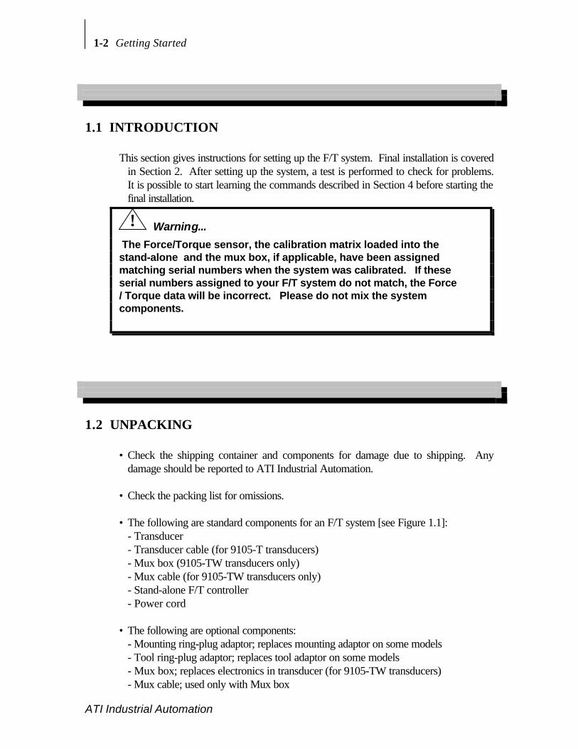
• Check the shipping container and components for damage due to shipping. Anydamage should be reported to ATI Industrial Automation.
• Check the packing list for omissions.
• The following are standard components for an F/T system [see Figure 1.1]:- Transducer- Transducer cable (for 9105-T transducers)- Mux box (9105-TW transducers only)- Mux cable (for 9105-TW transducers only)- Stand-alone F/T controller- Power cord
• The following are optional components:- Mounting ring-plug adaptor; replaces mounting adaptor on some models- Tool ring-plug adaptor; replaces tool adaptor on some models- Mux box; replaces electronics in transducer (for 9105-TW transducers)- Mux cable; used only with Mux box

Getting Started 1-3
ATI Industrial Automation
- Analog output card (installs in stand-alone F/T controller)- Serial software utilities for IBM PC compatible computers
Aside...
If your sensor has special features check Appendix C for additional information.
! Warning...
The transducer is susceptible to damage from electrostatic discharge whenever it is notconnected to the F/T system. Do not touch the electronics or the connector pins whenhandling the transducer.
Transducer
on-board
electronics
Connector
pins
Connector on
Transducer
1.3 SYSTEM COMPONENTS DESCRIPTION
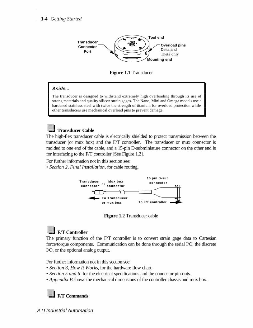
TransducerThe transducer is a compact, rugged, monolithic structure that converts force and torqueinto analog strain gage signals for the F/T controller. The transducer is commonly used as awrist sensor mounted between a robot and a robot end-effector. Factory-installedoverload pins give Delta and Theta transducers extra protection from damage due toinadvertent overloads. Figure 1.1 shows the transducer with a standard tool adaptor.
• If your system has the Dual Gain Calibration Option see Appendix D forinstructions on selecting the individual calibrations.
For further information not in this section see:• Appendix A for specifications (i.e. resolution, weight).• Appendix B for mechanical drawings.• Section 2, Final Installation, for mounting and cable routing.
1-4 Getting Started
ATI Industrial Automation
Transducer Connector
Port
Tool end
Mounting end
Overload pins Delta and Theta only
Figure 1.1 Transducer
Aside...
The transducer is designed to withstand extremely high overloading through its use ofstrong materials and quality silicon strain gages. The Nano, Mini and Omega models use ahardened stainless steel with twice the strength of titanium for overload protection whileother transducers use mechanical overload pins to prevent damage.
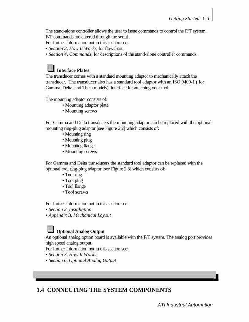
Transducer CableThe high-flex transducer cable is electrically shielded to protect transmission between thetransducer (or mux box) and the F/T controller. The transducer or mux connector ismolded to one end of the cable, and a 15-pin D-subminiature connector on the other end isfor interfacing to the F/T controller [See Figure 1.2].For further information not in this section see:• Section 2, Final Installation, for cable routing.
Transducer connector
To Transducer or mux box To F/T controller
15 pin D-sub connectorMux box
connectoro r
Figure 1.2 Transducer cable
F/T ControllerThe primary function of the F/T controller is to convert strain gage data to Cartesianforce/torque components. Communication can be done through the serial I/O, the discreteI/O, or the optional analog output.
For further information not in this section see:• Section 3, How It Works, for the hardware flow chart.• Section 5 and 6 for the electrical specifications and the connector pin-outs.• Appendix B shows the mechanical dimensions of the controller chassis and mux box.
F/T Commands
Getting Started 1-5
ATI Industrial Automation
The stand-alone controller allows the user to issue commands to control the F/T system.F/T commands are entered through the serial .For further information not in this section see:• Section 3, How It Works, for flowchart.• Section 4, Commands, for descriptions of the stand-alone controller commands.
Interface PlatesThe transducer comes with a standard mounting adaptor to mechanically attach thetransducer. The transducer also has a standard tool adaptor with an ISO 9409-1 ( forGamma, Delta, and Theta models) interface for attaching your tool.
The mounting adaptor consists of:• Mounting adaptor plate• Mounting screws
For Gamma and Delta transducers the mounting adaptor can be replaced with the optionalmounting ring-plug adaptor [see Figure 2.2] which consists of:
• Mounting ring• Mounting plug• Mounting flange• Mounting screws
For Gamma and Delta transducers the standard tool adaptor can be replaced with theoptional tool ring-plug adaptor [see Figure 2.3] which consists of:
• Tool ring• Tool plug• Tool flange• Tool screws
For further information not in this section see:• Section 2, Installation• Appendix B, Mechanical Layout
Optional Analog OutputAn optional analog option board is available with the F/T system. The analog port provideshigh speed analog output.For further information not in this section see:• Section 3, How It Works.• Section 6, Optional Analog Output
1.4 CONNECTING THE SYSTEM COMPONENTS
1-6 Getting Started
ATI Industrial Automation
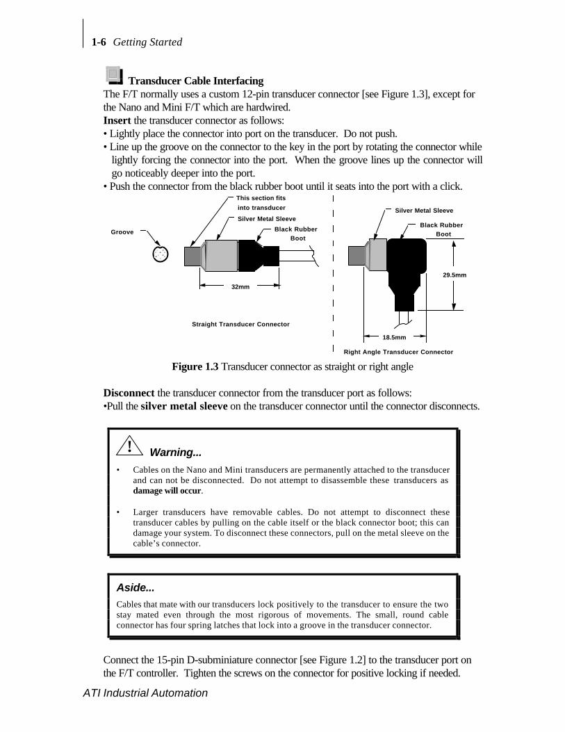
Transducer Cable InterfacingThe F/T normally uses a custom 12-pin transducer connector [see Figure 1.3], except forthe Nano and Mini F/T which are hardwired.Insert the transducer connector as follows:• Lightly place the connector into port on the transducer. Do not push.• Line up the groove on the connector to the key in the port by rotating the connector while
lightly forcing the connector into the port. When the groove lines up the connector willgo noticeably deeper into the port.
• Push the connector from the black rubber boot until it seats into the port with a click.
Groove
Silver Metal Sleeve
Black Rubber Boot
32mm
18.5mm
Silver Metal Sleeve
Black Rubber Boot
Straight Transducer Connector
Right Angle Transducer Connector
29.5mm
This section fits
into transducer
Figure 1.3 Transducer connector as straight or right angle
Disconnect the transducer connector from the transducer port as follows:•Pull the silver metal sleeve on the transducer connector until the connector disconnects.
! Warning...
• Cables on the Nano and Mini transducers are permanently attached to the transducerand can not be disconnected. Do not attempt to disassemble these transducers asdamage will occur.
• Larger transducers have removable cables. Do not attempt to disconnect thesetransducer cables by pulling on the cable itself or the black connector boot; this candamage your system. To disconnect these connectors, pull on the metal sleeve on thecable’s connector.
Aside...
Cables that mate with our transducers lock positively to the transducer to ensure the twostay mated even through the most rigorous of movements. The small, round cableconnector has four spring latches that lock into a groove in the transducer connector.
Connect the 15-pin D-subminiature connector [see Figure 1.2] to the transducer port onthe F/T controller. Tighten the screws on the connector for positive locking if needed.

Getting Started 1-7
ATI Industrial Automation
Serial Port InterfacingThe following instructions are for connecting a serial device (i.e. personal computer, HyperTerminal in Windows Accessories, RS-232 terminal, etc.) to communicate with the F/Tcontroller:• The user must provide the serial device.• The user must provide a serial port cable with a male 9-pin D-subminiature connector on
one end for connecting to the F/T controller and a connector to mount to the serialdevice.
• See Section 5 for the F/T Controller's serial port pin-out [see Tables 1.1 and 1.2 forconnection information].
F/T Stand-alone ControllerRS-232 port
9-pin Computeror TerminalRS-232 Port
Equipment Connector Type Male 9-pinD-Subminiature
Male 9-pinD-Subminiature
Cable Connector Type Female 9-pin D-Subminiature Female 9-pin D-SubminiatureGround Signal pin 5 pin 5
F/T Transmit Signal pin 3 pin 2F/T Receive Signal pin 2 pin 3
Table 1.1 Serial port interfacing to a 9-pin RS-232 port
F/T Stand-alone ControllerRS-232 port
25-pin Computeror TerminalRS-232 Port
Equipment Connector Type Male 9-pinD-Subminiature
Female 25-pinD-Subminiature
Cable Connector Type Female 9-pin D-Subminiature Male 25-pinD-Subminiature
Ground Signal pin 5 pin 7F/T Transmit Signal pin 3 pin 3F/T Receive Signal pin 2 pin 2
Table 1.2 Serial port interfacing to a 25-pin RS-232 port
• Select the serial device attributes: 8-bit transmission with no parity and one stop bit.• Select baud rate on F/T controller [see Figure 1.4] to match the baud rate of the Serial
Device. The baud rate is factory preset to 9600.

1-8 Getting Started
ATI Industrial Automation
Using Hyper Terminal in Windows 9X/NT/2000 forSerial Communications
Hyper Terminal can be found in the Start menu under Programs / AccessoriesCommunications. Note: If the program is not present you will need to install it fromWindows setup. Hyper Terminal is located as a communications options. StartHypertrm.exe to create a new connection, select which com port you are using. Ex.Connect using: Direct to Com 1. And set the Port Settings to the following values tocommunicate with the factory controller setup.
• Bits per second : 9600• Data bits : 8• Parity : None• Stop bits : 1• Flow control : Xon/Xoff
! Warning...
Always turn off the power switch and unplug the F/T controller’s power cord beforeremoving the F/T controller’s cover to prevent electrical shock.
! Warning...
The F/T controller’s printed circuit board is susceptible to damage from static discharge. Ifpossible, work at an anti-static workstation and ground yourself before touching theprinted circuit board.
! Caution...
The controller contains a lithium battery. The battery must be disposed of per localregulations.

Getting Started 1-9
ATI Industrial Automation
F r o n t o f c o n t r o l l e r
R e a r o f c o n t r o l l e r
P o w e r
S w i t c h
F/T Controller PC board Components are not to scale and are shown for orientation.
B a u d R a t e S w i t c h
b e t w e e n L E D s
1 2 3 4
B a t t e r y
1 2 3 4
+ -B A U D R A T E S 38.4K
19.2K
12009600
12
34
OPEN
Open
Position
Closed Position
Either
38.4K1 2 3 4
OPEN
19.2K1 2 3 4
OPEN
12001 2 3 4
OPEN
9600 Default
12
34
OP
EN
Top v i ew o f F /T Contro l l er w i th cover removed
WA
RN
IN
G:
DA
NG
ER
OU
S V
OL
TA
GE
!
V o l t a g e
S e l e c t o r
S w i t c h
Dot means down
+ -
115S E R I A L N U M B E R
Figure 1.4 Location of the baud rate and voltage selector switches on F/T controller
Power Cord Connection• Verify that the voltage rating is correct for your facility. See label attached under power
socket. If necessary change the F/T Controller's voltage input to either 115V or 230V[see Figure 1.8 for locating the voltage selector switch]. Turn off the power anddisconnect the power cord from the F/T controller’s power socket beforeremoving the cover.
• Turn the power switch to the off position.• Plug the power cord into the F/T controller's power socket.• Plug the power cord into a AC outlet.
1.5 TESTING THE F/T SYSTEM
Turning On the F/T Controller• With the F/T system connected as described in Section 1.4, turn the power switch on.• The green power LED will turn on and glow green.

1-10 Getting Started
ATI Industrial Automation
• The red LED will blink on and off to verify that the diagnostic checks have passed. If thered LED stays on this signifies an error.
• A header message will appear on the serial device [See Figure 1.5].• A “>” prompt will appear after the header message.
NOTE: Please see Appendix A of this manual for actual force, torque, and countvalues for your sensors calibration. There may be rounding in the Headermessage displayed for your system. Header Displays: 5, Actual: 4.8
F30/T100(40/40) SN FT0000-3F Version 5.00Copyright(c) 1990, 1991, 1992 by Assurance Technologies, Inc. Garner, NCAll Rights Reserved
>
Figure 1.5 Header message and prompt
Aside...
1. <CR> indicates a carriage return (enter) character.2. Commands entered by the user are displayed as bold.3. If you experience problems check your electrical connections (see Section 7,
Troubleshooting Guide) and commands (see Section 4, Commands).4. Commands are not case sensitive so they may entered in upper- or lower-case.
Warm Start, ^W• At the prompt type Control-W, ^W.• The F/T system is reset and the screen displays the header message and prompt.
Reset Button• Push the reset button on the front panel. The button is recessed inside the F/T controller
chassis. Use a small object to push the button.• The F/T system is reset and the screen displays the header message and prompt.
Output ASCII Force Vector (Serial Port) and Biasing• At the prompt type CD A<CR>. This selects the ASCII format output.
Indicates ratedforce and torque(F30/T100 means30 lbs, 100 lb-in)
See Appendix A of this manual for theactual counts for your system
SerialNumber
3F indicates this system senses 6-DOF: Fx, Fy , Fz, Tx, Ty , and Tz
Stand-alone controllerFirmware version
Systemprompt
Getting Started 1-11
ATI Industrial Automation
• At the prompt type CD R<CR>. This selects the resolved force/torque data for outputinstead of the strain gage data.
• At the prompt type QS<CR>. Continuous output of the resolved data will beginscrolling across the screen. Touch the transducer front plate and note how theforce/torque values change. See the transducer drawing in Appendix B, MechanicalLayout, for the sensor frame to locate the X, Y, and Z orientation on the transducer.
• Type SB<CR>. The data will stop and the prompt will return. The resolved data hasbeen biased. Repeat the command QS<CR>. The resolved force/torque data will readclose to zero.
• Type <CR>. The data will stop and the prompt will return.
Using the Zip Macro Start-up, ZC• Type ZC 0, "CD A; CD R; QS"<CR>. This stores the commands within the double
quote into the start-up macro.• Reset the system by any of the three methods shown (e.g. Control-W).• The commands execute at the end of the header message.• Type <CR> to halt the output. The prompt will return to the screen.• Type ZC 0, ""<CR>. This will clear the start-up macro.• Reset the F/T system. The header message will appear with the prompt and without any
commands being executed.
hhhh hhhh hhhh

1-12 Getting Started
ATI Industrial Automation
This page intentionally left blank.

2 Installation
Section Page
2.1 INTRODUCTION ...................................................................................................2-22.2 ROUTING THE TRANSDUCER CABLE............................................................2-22.3 MOUNTING THE TRANSDUCER ......................................................................2-3
Transducer Mounting Method I, Standard Mounting Adaptor..........................2-3Transducer Mounting Method II, Mounting Ring-plug Adaptor.......................2-4Transducer Mounting Method III, User-designed Interface .............................2-5
2.4 MOUNTING YOUR TOOL....................................................................................2-6Tool Mounting Method I, Standard Tool Adaptor..............................................2-6Tool Mounting Method II, Optional Tool Ring-plug Adaptor............................2-6
2-2 Installation
ATI Industrial Automation
2.1 INTRODUCTION
This section will assist the user in mounting the transducer, your tool, and the transducercable.
2.2 ROUTING THE TRANSDUCER CABLE
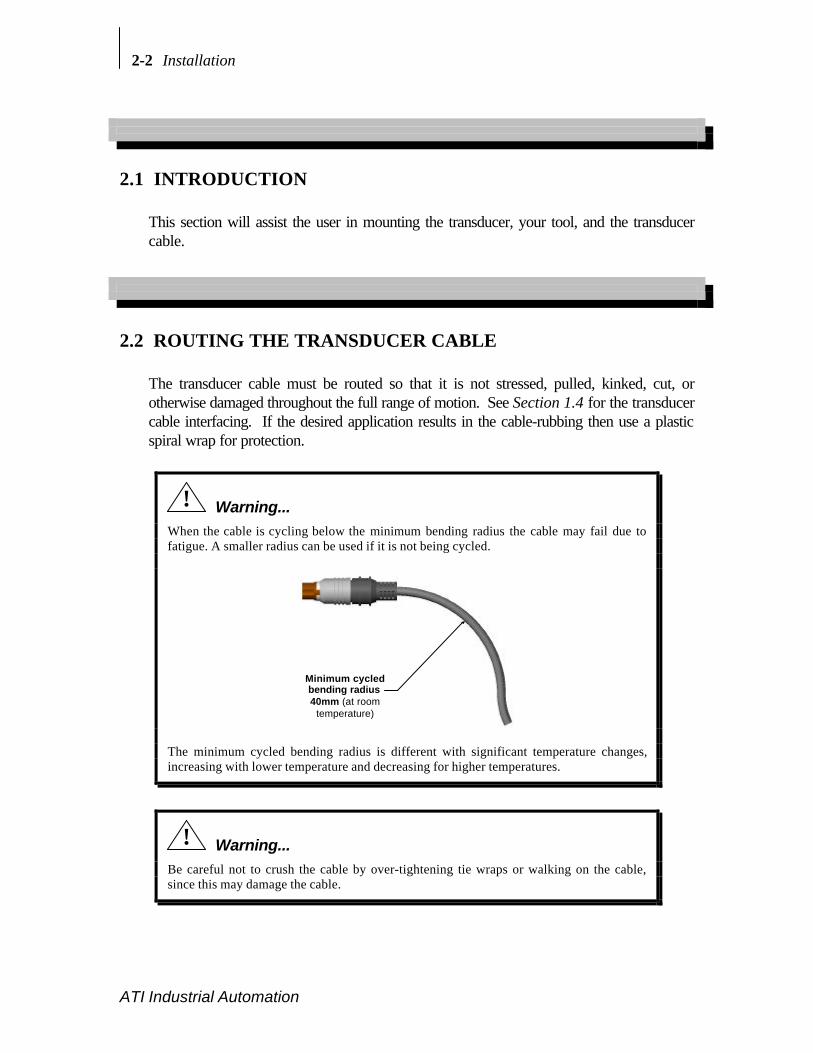
The transducer cable must be routed so that it is not stressed, pulled, kinked, cut, orotherwise damaged throughout the full range of motion. See Section 1.4 for the transducercable interfacing. If the desired application results in the cable-rubbing then use a plasticspiral wrap for protection.
! Warning...
When the cable is cycling below the minimum bending radius the cable may fail due tofatigue. A smaller radius can be used if it is not being cycled.
Minimum cycledbending radius40mm (at room
temperature)
The minimum cycled bending radius is different with significant temperature changes,increasing with lower temperature and decreasing for higher temperatures.
! Warning...
Be careful not to crush the cable by over-tightening tie wraps or walking on the cable,since this may damage the cable.
Installation 2-3
ATI Industrial Automation
2.3 MOUNTING THE TRANSDUCER
There are three different methods, I, II, and III, for mounting most F/T transducers. Mountthe transducer to a structure with sufficient mechanical strength. Not doing so can lead tosub optimum performance. The Nano, Mini and Omega transducers have mountingand tool adaptors which cannot be removed, so only method III can be used. Adetailed description is given on the following pages and a brief description is given below:
Transducer Mounting Method I: Uses the standard mounting adaptor to attach thetransducer. You must machine the bolt pattern of your device (i.e. robot) into the mountingadaptor. You will not be able to use the mounting adaptor alone if your device covers themounting screws used to connect the transducer. If this is the case use either method II ormethod III instead.
Transducer Mounting Method II: Uses the optional mounting ring-plug adaptor as areplacement for the standard mounting adaptor. You must machine the mounting plug toattach to your device. The mounting ring-plug adaptor has the benefit of allowing thetransducer to be connected and disconnected by hand (disconnecting may require strapwrench). If the bolt pattern on your device can fit on the plug and you have access to thering then the mounting ring-plug adaptor will work. If the bolt pattern is larger than theplug, use method III.
Transducer Mounting Method III: Use your own interface plate to bolt directly to thetransducer or (for the Nano, Mini or Omega models) the mounting adaptor.
Use Appendix B, Mechanical Layout, for detailed mechanical drawings of thetransducer and all interface plates. Detailed descriptions of each method are shown onthe next two pages.
Aside...
Examine the sensor frame and cable routing section before modifying the mountingadaptor plates. The F/T system’s default sensor frame sets the transducer’s point oforigin at the center of the mounting adaptor’s surface. See Appendix B, MechanicalLayout, for drawings showing the default point of origin.
Transducer Mounting Method I, Standard Mounting AdaptorUse the mounting adaptor to attach the transducer as follows:• Ensure that you provide sufficient clearances between the mounted transducer and other
fixtures, and that total stack height is acceptable. Also ensure that after the mountingadaptor is attached to the robot (or other device) you will have access to the mountingscrews for attaching the transducer.

2-4 Installation
ATI Industrial Automation
• Machine the mounting adaptor plate for attaching to your robot (or other device).Mounting adaptor plate dimensions are shown in Appendix B, Mechanical Layout [seeFigure 2.1]. All user-supplied screws must be flush with the inside of themounting adaptor to ensure proper clearance for the electronics inside thetransducer.
• Attach the mounting adaptor to the robot (or other device). Attach the transducer to themounting adaptor with the screws and dowel pin provided. Thread locker isrecommended to prevent the screws from backing out due to vibration (e.g. Loctitethread locker No. 222).
Tool side
Mounting side
Transducer
Robot (or other device)
Mounting screws provided
with threaded bolt circle
Mounting adaptor plate
User-supplied flat head screws
User-machined counter sinks to match threaded bolt circle
Figure 2.1 Attaching the transducer with the mounting adaptor
Transducer Mounting Method II, Mounting Ring-plug Adaptor• Ensure that you provide sufficient clearances between the mounted transducer and other
fixtures, and that total stack height is acceptable. Also ensure that you will have room fortightening the mounting ring
• Machine the mounting plug for attaching to your robot (or other device). Mounting plugdimensions are shown in Appendix B [see Figure 2.2].
• Attach the mounting plug, then attach the transducer to the mounting plug using theattached mounting ring and flange.

Installation 2-5
ATI Industrial Automation
Transducer
Mounting side
Tool side
Mounting flange plate
Mounting plug to be machined
Mounting Ring
Turn mounting ring this direction to loosen
Figure 2.2 Using the mounting ring-plug adaptor
Aside...
How the ring/plug adaptor works: The flange plate is held to the transducer with screwsand dowel pins. The plug mates to the flange plate with a center boss and a dowel pin.The plug also mates to the ring with matching threads. When the ring is turned the plugscrews into the ring causing the plug to clamp to the flange plate.
Aside...
If the ring cannot be removed by hand, use a strap wrench to loosen it. A strap wrenchcan be purchased through a supply company such as McMaster-Carr (PN 5378A1).
Transducer Mounting Method III, User-designed InterfaceThe transducer can be mounted using the bolt pattern provided; see Appendix B,Mechanical Layout.
! Warning...
Do not attempt to drill, tap, machine, or otherwise modify the transducer. This coulddamage the transducer and will void the warranty. Do not attempt to remove any part ofNano, Mini or Omega model transducers as damage will occur.

2-6 Installation
ATI Industrial Automation
2.4 MOUNTING YOUR TOOL
There are two methods for mounting your tool to most F/T transducers. Method II canonly be used for the Gamma and Delta transducers. The two methods are describedbelow:
Tool Mounting Method I, Standard Tool AdaptorThe tool adaptor is factory installed and the bolt circle is shown in Appendix B,Mechanical Layout. Most F/T tool adaptors follow the ISO 9409-1 mounting pattern.Machine your tool interface plate to attach to this bolt circle.
Tool Mounting Method II, Optional Tool Ring-plug Adaptor• This method is similar to the optional mounting ring-plug adaptor. See Section 2.3,
MOUNTING THE TRANSDUCER, Method II, Optional Mounting Ring-plugAdaptor for details.
• Ensure that you provide sufficient clearances between the mounted transducer and otherfixtures, and that total stack height is acceptable. Also ensure that you will have room fortightening the tool ring
• Machine the tool plug for mounting to the end-effector. The dimensions of the tool plugare shown in Appendix B, Mechanical Layout [see Figure 2.3].
• Mount the tool plug to your tool. Then mount the transducer to the tool plug using theattached tool ring and tool flange. See the “Aside” notes in section 2.3 for how the ring-plug adaptor works. The tool flange is not attached to the standard tool adaptor, butreplaces it.
T r a n s d u c e r
Toolside
Mountingside
Tool p lugto be
machined
Tool ring &tool f lange
factory installed
Turn tool ringthis direction
to loosen
Figure 2.3 Using the tool ring-plug adaptor

Installation 2-7
ATI Industrial Automation
! Warning...
Your tool may only touch the tool adaptor plate. If your tool touches any other part of thetransducer it will not properly sense loads.
hhhh hhhh hhhh

2-8 Installation
ATI Industrial Automation
This page intentionally left blank.

3 How ItWorks
Section Page
3.1 INTRODUCTION ...................................................................................................3-23.2 ELECTRONIC HARDWARE................................................................................3-23.3 SOFTWARE OUTLINE..........................................................................................3-33.4 MECHANICAL DESCRIPTION...........................................................................3-3

3-2 How It Works
ATI Industrial Automation
3.1 INTRODUCTION
This section provides a functional outline of the F/T system. The F/T system is broken intothree areas; electrical, controlling software, and mechanical. A graphical representation of theelectronics is presented in Section 3.2. A controlling software flow chart is shown in Section3.3. A mechanical description is shown in Section 3.4.
3.2 ELECTRONIC HARDWARE
Figure 3.1 Electronic hardware outline

How It Works 3-3
ATI Industrial Automation
3.3 SOFTWARE OUTLINE
Figure 3.2 Controller flowchart
3.4 MECHANICAL DESCRIPTION
The property of forces was first stated by Newton in his third law of motion: “To everyaction there is always opposed an equal reaction; or, the mutual action of two bodiesupon each other are always equal, and directed to contrary parts.” The transducerreacts to applied forces and torques using Newton’s third law.
3-4 How It Works
ATI Industrial Automation
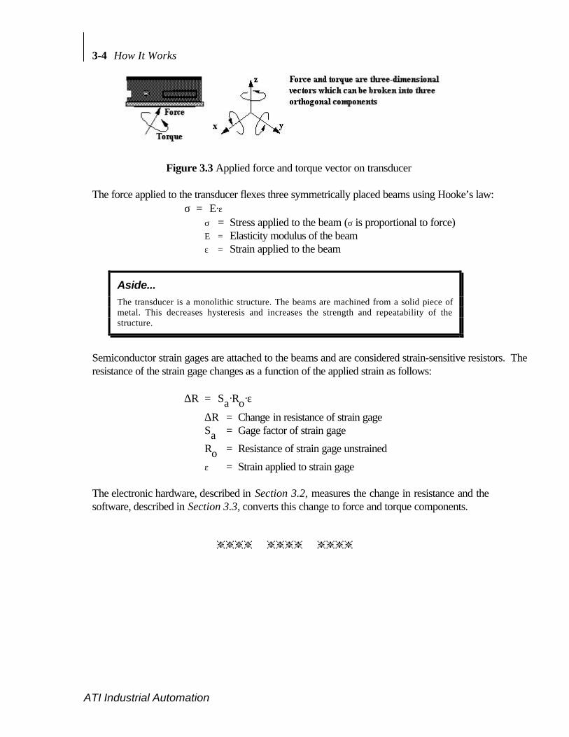
Figure 3.3 Applied force and torque vector on transducer
The force applied to the transducer flexes three symmetrically placed beams using Hooke’s law:σ = E·ε
σ = Stress applied to the beam (σ is proportional to force)Ε = Elasticity modulus of the beamε = Strain applied to the beam
Aside...
The transducer is a monolithic structure. The beams are machined from a solid piece ofmetal. This decreases hysteresis and increases the strength and repeatability of thestructure.
Semiconductor strain gages are attached to the beams and are considered strain-sensitive resistors. Theresistance of the strain gage changes as a function of the applied strain as follows:
∆R = Sa·Ro·ε
∆R = Change in resistance of strain gageSa = Gage factor of strain gage
Ro = Resistance of strain gage unstrained
ε = Strain applied to strain gage
The electronic hardware, described in Section 3.2, measures the change in resistance and thesoftware, described in Section 3.3, converts this change to force and torque components.
hhhh hhhh hhhh

4 Commands
4.1 COMMAND OVERVIEW AND PROTOCOL.................................................... 4-24.2 COMMUNICATION SETUP COMMANDS ...................................................... 4-5
Sensor Error......................................................................................................... 4-5Communication Data Mode (CD A, CD B)........................................................ 4-5Communication Data Checksum (CD E, CD U)................................................. 4-6Communicate Data Type (CD D, CD H, CD R) ................................................ 4-7Communication Output Selection (CA b, CP a) .................................................. 4-8Other Communication Setup Commands (CF d, CL b, CV h)............................ 4-9
4.3 QUERY COMMANDS .......................................................................................... 4-11Query Data Request Commands (QR, ^T, ^N, QS).......................................... 4-11Query Calibration Matrix (QC)........................................................................... 4-12Query F/T Peaks (QP) ......................................................................................... 4-12
4.4 SENSOR COMMANDS ........................................................................................ 4-13Sensor Biasing (SB, SU, SZ)................................................................................ 4-13Optional Sensor Temperature Compensation (ST b) ......................................... 4-14Sensor Peaks (SP b, SC)...................................................................................... 4-16Sensor Error Message (SM b)............................................................................ 4-17Sensor Sampling Frequency (SF d) ..................................................................... 4-17Sensor Averaging (SA d) ..................................................................................... 4-18
4.5 DISCRETE I/O COMMANDS.............................................................................. 4-18I/O Verification (ID, OD h) ................................................................................. 4-18Force Monitoring Commands (MC s, MD d, ML)............................................. 4-20
4.6 TOOL FRAME COMMANDS............................................................................... 4-22Tool Frame Selection, Listing and Deleting (TF d, TL, TD d)........................... 4-23Tool Frame Construction (TC d, s, x, y, z, µ, ß, ø)............................................... 4-24
4.7 OTHER F/T COMMANDS ................................................................................... 4-25Zip Macro Create Start-up Buffer (ZC 0, "s")................................................... 4-25Warm Start (^W).................................................................................................. 4-26Filter Clock (FC d) ............................................................................................... 4-26XON and XOFF (^Q, ^S) .................................................................................... 4-26Store and Reload Run Memory (RS, RL).......................................................... 4-27

4-2 Commands
ATI Industrial Automation
4.1 COMMAND OVERVIEW AND PROTOCOLThe majority of commands consist of one to three ASCII characters. All commands can bein either upper or lower-case. Power-up or reset returns the F/T system to the defaultsettings. Table 4.1 gives a brief review of all commands described in this manual. Table 4.2reviews the nomenclature used in Table 4.1 and throughout this section.
COMMUNICATION SETUP COMMANDSCommunication Data Mode
CD A Setup communication for ASCII output mode (Default).CD B Setup communication for Binary output mode.
Communication ChecksumCD E Enable a checksum at the end of binary communication.CD U Unable sending checksum at end of binary communication (Default).
Communication Data TypeCD D Setup communication for Decimal strain gage data output.CD H Setup communication for Hexadecimal strain gage data output.CD R Setup communication for Resolved force data output (Default).
Other Communication Setup CommandsCA b Communicate Analog: enabled (b=1) or disabled (b=0; Default).CF d Communicate Fast: level 1, 2 or 3 or disabled (d=0; Default). Speeds up output.CL b Enable Linefeed <LF> with <CR> (b=1; Default) or disable <LF> output (b=0).CV h Selects components of F/T values to be transmitted (Fx, Fy, Fz, Tx, Ty, Tz).
QUERY DATA REQUESTSQuery F/T and Strain Gage Data
QR Query output of one Record of data in pre-selected communication setup.^T Speeds up data output by minimizing handshaking; similar to QR.QS Query output of a Stream of data in pre-selected type and mode.
Other Query CommandsQC Query the Calibration matrix in hexadecimal format. Used for error checking.QP Query Peaks: show the maximum and minimum F/T values collected (see SP).
SENSOR COMMANDS
Sensor BiasSB Performs a Sensor Bias. Stores bias reading in a 3 level buffer.SU Performs a Sensor Unbias. Removes last bias command from buffer.SZ Removes all previously stored biases from buffer.
Table 4.1 Command overview (continued on next page)
Optional Sensor Temperature CompensationST b Optional temperature compensation: enabled (b=1) or disabled (b=0; Default).

Commands 4-3
ATI Industrial Automation
Sensor Peaks (see QP command)SP b Collects the max. and min. F/T values: start (b=1) or stop (b=0; Default).SC Clear max. and min. F/T values by loading 9999 & -9999 in min. & max.
Other Sensor CommandsSM b Sensor Monitoring: disables (b=0) error message due to sensor error (saturation,
disconnected transducer etc.) or enables error message (b=1; Default).SF d Sensor sampling Frequency allows optimizing for faster output when using CF.SA d Performs a moving average of d sensor data samples (d=0; Default).
I/O VERIFICATIONID Reads and displays the state of all discrete input lines.OD h Sets the state of all discrete outputs as specified by hexadecimal number h.
FORCE MONITOR COMMANDSMC s Creates a force Monitor statement s.MD d Deletes a force Monitor statement d.ML List all stored Force Monitor statements.
TOOL FRAME COMMANDSTF d Selects a calibration matrix from tool frame list (d=0, 1, 2 or 3).TL List available tool frames.TD d Delete tool frame (d=1, 2 or 3).TC d,s,x, y,z,µ,ß,ø
Constructs a new tool frame by changing the coordinate system (d=0..3; s=name; x, y,and z = translation; µ, ß, and ø = rotation).
MISCELLANEOUS COMMANDS^W Warm start. Performs a system reset and is identical to pressing the reset button.FC d Sets the Filter Clock output (for Analog option).^Q, ^S XON and XOFF.ZC 0, "s" Creates a buffer of commands, s, that are executed at system power-up or reset.RS Save values from run memory into permanent memory.RL Reload values from permanent memory into run memory.
Table 4.1 Command overview (continued from previous page)
4-4 Commands
ATI Industrial Automation
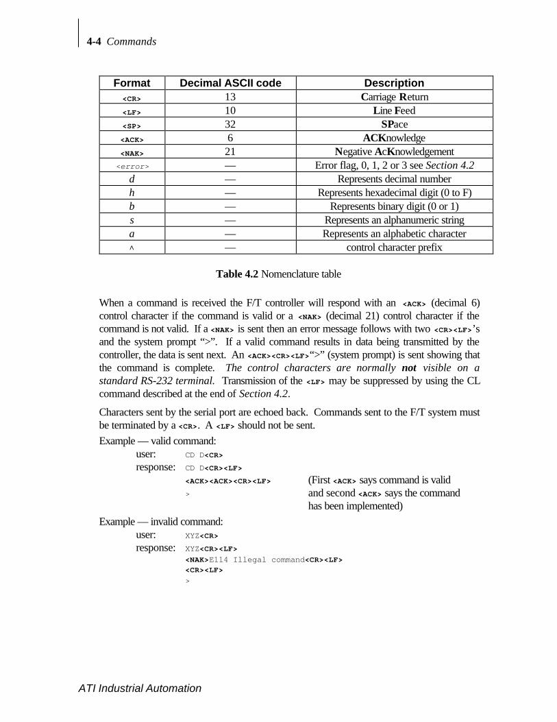
Format Decimal ASCII code Description<CR> 13 Carriage Return<LF> 10 Line Feed<SP> 32 SPace<ACK> 6 ACKnowledge<NAK> 21 Negative AcKnowledgement<error> — Error flag, 0, 1, 2 or 3 see Section 4.2
d — Represents decimal numberh — Represents hexadecimal digit (0 to F)b — Represents binary digit (0 or 1)s — Represents an alphanumeric stringa — Represents an alphabetic character^ — control character prefix
Table 4.2 Nomenclature table
When a command is received the F/T controller will respond with an <ACK> (decimal 6)control character if the command is valid or a <NAK> (decimal 21) control character if thecommand is not valid. If a <NAK> is sent then an error message follows with two <CR><LF>’sand the system prompt “>”. If a valid command results in data being transmitted by thecontroller, the data is sent next. An <ACK><CR><LF>“>” (system prompt) is sent showing thatthe command is complete. The control characters are normally not visible on astandard RS-232 terminal. Transmission of the <LF> may be suppressed by using the CLcommand described at the end of Section 4.2.
Characters sent by the serial port are echoed back. Commands sent to the F/T system mustbe terminated by a <CR>. A <LF> should not be sent.Example — valid command:
user: CD D<CR>
response: CD D<CR><LF>
<ACK><ACK><CR><LF> (First <ACK> says command is valid> and second <ACK> says the command
has been implemented)Example — invalid command:
user: XYZ<CR>
response: XYZ<CR><LF><NAK>E114 Illegal command<CR><LF><CR><LF>
>

Commands 4-5
ATI Industrial Automation
4.2 COMMUNICATION SETUP COMMANDS
The F/T controller outputs three types of data through the RS-232 serial port: raw straingage data in hexadecimal format, raw strain gage data in decimal integer format, andresolved force/torque data in decimal integer unit format. Data is available in either ASCIIor binary format output mode. The length (in bytes) of an output record depends upon thetype of data and the output mode. One “record” of data refers to a single set of strain gagereadings or the resolved forces/torques. Also, “SG0” represents strain gage bridge 0,“SG1” represents strain gage bridge 1, etc. “Low” and “high” refer to low and high bytesof data.
Resolved force/torque data is transmitted in decimal integer unit format. The value of oneunit force or one unit torque varies depending upon the model and the calibration, seecommand CD R for further information.
The Communication Data (CD) commands control the output data mode and type. Thedefault at power-up or reset is ASCII output format and resolved force data output type.The mode or type of data may be changed by issuing the appropriate command. The newmode or type remains in effect until a different mode or type is selected or the system isreset.
Sensor ErrorIn the following command descriptions <error> represents the sensor error flag set by theF/T controller. The <error> flag can be a 0, 1, 2 or 3. The flag is normally 0 and is set to 1if the forces on the system exceed the range (saturation). A flag value of 2 indicates that atransducer error has occurred such as a broken gage or disconnected transducer cable. Avalue of 3 indicates that saturation and transducer error have occurred simultaneously.When a sensor error occurs the following will occur:
a) The health output line on the discrete I/O is turned off.b) The error LED on the controller front is turned on.c) Unless disabled the data output through the serial port produces an error message that
will continue to repeat until the saturation and/or transducer error is stopped or thecommand “SM 0” is issued.
d) The error flag, <error>, is set to 1, 2 or 3.
The <error> flag is transmitted as an ASCII character or as a binary byte depending on thedata mode selected.
Communication Data Mode (CD A, CD B)Output can be in ASCII mode or binary mode. ASCII mode has the benefit of providingdata in readable characters, but has a slower output rate due to the larger number of bytes in

4-6 Commands
ATI Industrial Automation
each record. Binary output has the benefit of faster output due to the smaller number ofbytes needed to carry information, but cannot be read without further computation. Thefollowing commands select the data mode:
• CD A Communicate Data ASCIISelects ASCII output mode; default. All data transmitted in response to data querycommands will be in ASCII format. XON/XOFF software handshaking is supported.
CD A command format:user: CD A<CR>
response: CD A<CR><LF><ACK><ACK><CR><LF>
>
• CD B Communicate Data BinarySelects binary output mode. All data transmitted in response to data query commandswill be in binary format. XON/XOFF software handshaking is not supported.
CD B command format:user: CD B<CR>
response: CD B<CR><LF><ACK><ACK><CR><LF>
>
! Important...
When the controller is in binary mode (CD B), all numerical output will be in binary. Thisincludes not only output data, but error messages as well. In ASCII mode (CD A), allnumeric output will be readable.
Communication Data Checksum (CD E, CD U)You can append a checksum to the end of force/torque data or strain gage data beingsent in binary mode (see commands CD B, CD D, CD H, and CD R). A checksum willallow you to check the data for transmission errors. Appending the checksum will slowdata transmission slightly.
• CD E Communicate Data checksum EnabledAppends checksum to end of strain gage or F/T binary record. The checksum is eightbits for serial output. The checksum is calculated by adding each value being sent,including the error byte (which is zero when no saturation or error is present), anddropping the most significant byte for the serial output; see the example below. TheASCII decimal data for the example is 1, 102, 14, 7723, 106, -158, -5138 where theerror flag shows that the sensor is saturated. The prefix “0x” indicates a hexadecimalnumber. Serial output are converted to most and least significant bytes as follows:
7723 = 0x1E2B where 0x1E = 30 & 0x2B = 43106 = 0x006A where 0x00 = 0 & 0x6A =106
-158 = 0xFF62 where 0xFF = 255 & 0x62 = 98

Commands 4-7
ATI Industrial Automation
Serial F/T binary output: <1><0><102><0><14><30><43><0><106><255><98><235><238><98>1+0+102+0+14+30+43+0+106+255+98+235+238 = 1122 = 0x0462drop the most significant byte leaving 6216= 9810
• CD U Communicate Data checksum Disabled (Un-enable)Stop sending the checksum. This command is the default.
Communicate Data Type (CD D, CD H, CD R)Strain gage data or resolved force data can be selected for output. The followingcommands select the type of output:
• CD D Communicate Data Decimal gageSelects raw decimal strain gage data for output. Six strain gage readings are output eachhaving a value from -2048 to 2047. In some special cases the sensor has eight straingage readings. The examples are given for six gages.
CD D command format:user: CD D<CR>
response: CD D<CR><LF><ACK><ACK><CR><LF>
>
In ASCII mode one data record consists of 45 bytes for six strain gages with linefeedsenabled. The first byte is the error flag followed by a comma and the strain gage datawhich is right-justified in six fields of six bytes each, separated by commas. The finalbytes are <CR><LF>. The <LF> is not transmitted if it has been disabled by the CLcommand.
In binary mode each record consists of 13 bytes for six strain gages and the checksumturned off (see CD U and CD E commands). The first byte is the error flag, followed bythe six strain gage data values, which consist of two bytes with the high byte transmittedfirst.Data format of one raw strain gage record in ASCII and binary mode:ASCII: <error>,XXXXXX,XXXXXX,XXXXXX,XXXXXX,XXXXXX,XXXXXX<CR><LF>
SG0 SG1 SG2 SG3 SG4 SG5Binary: <error><SG0 high><SG0 low><SG1 high><SG1 low><SG2 high>
<SG2 low><SG3 high><SG3 low><SG4 high><SG4 low><SG5 high><SG5 low>
• CD H Communicate Data Hex gageSelects raw hexadecimal strain gage data for output. Six strain gage readings are output.In some special cases the sensor may output eight strain gage readings.
CD H command format:user: CD H<CR>
response: CD H<CR><LF><ACK><ACK><CR><LF>
>
4-8 Commands
ATI Industrial Automation
Data format is similar to that of CD D except there on four bytes for each field instead ofsix.
Aside...
For some special systems (non-standard) the transducer has eight strain gages. If yourtransducer has eight strain gages adjust the examples for the extra two gages.
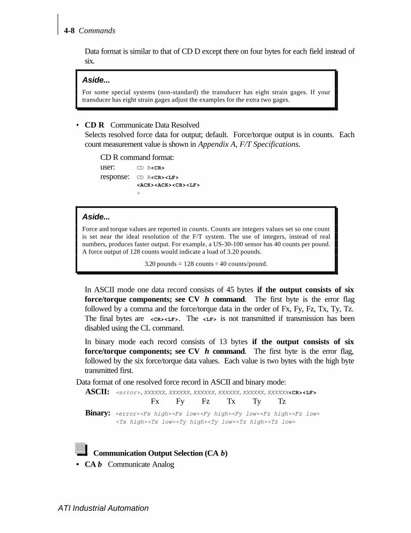
• CD R Communicate Data ResolvedSelects resolved force data for output; default. Force/torque output is in counts. Eachcount measurement value is shown in Appendix A, F/T Specifications.
CD R command format:user: CD R<CR>
response: CD R<CR><LF><ACK><ACK><CR><LF>
>
Aside...
Force and torque values are reported in counts. Counts are integers values set so one countis set near the ideal resolution of the F/T system. The use of integers, instead of realnumbers, produces faster output. For example, a US-30-100 sensor has 40 counts per pound.A force output of 128 counts would indicate a load of 3.20 pounds.
3.20 pounds = 128 counts ÷ 40 counts/pound.
In ASCII mode one data record consists of 45 bytes if the output consists of sixforce/torque components; see CV h command. The first byte is the error flagfollowed by a comma and the force/torque data in the order of Fx, Fy, Fz, Tx, Ty, Tz.The final bytes are <CR><LF>. The <LF> is not transmitted if transmission has beendisabled using the CL command.
In binary mode each record consists of 13 bytes if the output consists of sixforce/torque components; see CV h command. The first byte is the error flag,followed by the six force/torque data values. Each value is two bytes with the high bytetransmitted first.
Data format of one resolved force record in ASCII and binary mode:ASCII: <error>,XXXXXX,XXXXXX,XXXXXX,XXXXXX,XXXXXX,XXXXXX<CR><LF>
Fx Fy Fz Tx Ty TzBinary: <error><Fx high><Fx low><Fy high><Fy low><Fz high><Fz low>
<Tx high><Tx low><Ty high><Ty low><Tz high><Tz low>
Communication Output Selection (CA b)• CA b Communicate Analog

Commands 4-9
ATI Industrial Automation
Enables or disables the sending of force/torque or gage data to the analog port. Theanalog port is optional. The analog port can output data together with the serial port.When the analog port is disabled invalid data is sent.
b = 0 stops sending updated force/torque or gage data to the analog port; default.b = 1 enable current force/torque data to be sent to the analog port.
CA b command format:user: CA 1<CR>
response: CA 1<CR><LF><ACK><ACK><CR><LF>
>
If a value for b is omitted the system will indicate the current state of the analogoutput port.
CA command format:user: CA<CR>
response: CA<CR><LF><ACK>Analog outputs enabled<CR><LF><ACK><CR><LF>
>
Other Communication Setup Commands (CF d, CL b, CV h)• CF d Communicate Fast
Streamlines processing of output data. Disabled by default. When CF is enabledcommunication data rates increase. The increase is accomplished by temporarilydisabling certain software functions. The software is disabled in three levels as shown:d=0: Level 0. CF command is disabled and the software commands shown below are
restored to their normal state.
d=1: Level 1. Monitor conditions and sensor averaging (SA command) are disabled.
d=2: Level 2. Sensor Biasing is disabled. If the system is currently biased then thesystem will revert to the original resolved force/torque output (unbiased). Level 1is included in this level.
d=3: Level 3. Saturation monitoring is disabled. If saturation occurs with this levelenabled then no indication of saturation will occur. The error flag will not changefrom 0 to 1; however, the transducer error checking is still active (e.g.disconnected transducer cable) and will cause the error flag to change from 0 to 2.Level 1 and 2 are included in this level.
CF d command format:user: CF 1<CR>
response: CF 1<CR><LF><ACK><ACK><CR><LF>
>
If a value for d is omitted the system will indicate the current state of the CFcommand.
CF command format:user: CF<CR>

4-10 Commands
ATI Industrial Automation
response: CF<CR><LF><ACK>Fast mode 1 enabled<CR><LF><ACK><CR><LF>
>
• CL b Communicate LinefeedEnables or disables transmission of a linefeed, <LF>, character following every carriagereturn, <CR>, transmitted by the controller. Some serial devices output a <LF> for each<CR> received and it is suggested that the <LF> from the F/T controller be disabled toprevent two <LF> from appearing on the screen.
b = 0 disable linefeed transmissionb = 1 enable linefeed transmission; defaultCL b command format:user: CL 1<CR>
response: CL 1<CR><LF>
<ACK><ACK><CR><LF> (Line feed is now enabled)>
If a value for b is omitted the system will indicate the current value of b.CL command format:user: CL<CR>response: CL<CR><LF>
<ACK>Line feed enabled<CR><LF><ACK><CR><LF>
>
• CV h Communicate VectorThis command selects force/torque components for transmission, allowing you to simplifyor speed up processing. The value h is a hexadecimal number where each bit representsa force or torque component. The value of h is determined as follows:
(bits): 5 4 3 2 1 0Component enabled: Tz Ty Tx Fz Fy FxExample:
CV 14<CR> (Enables Ty and Fz)14 hex = 00010100 binary (The 1 in the third and fifth position
represent Fz and Ty)Attempting to enable a nonexistent component (with a system having fewer than 6components) will generate an error. The system defaults to the factory settings.
CV h command format:user: CV 14<CR>
response: CV 14<CR><LF>
<ACK><ACK><CR><LF> (Enables only Ty and Fz)>
If a value for h is omitted the system will indicate the current value of h.CV command format:user: CV<CR>
Commands 4-11
ATI Industrial Automation
response: CV<CR><LF><ACK>14<CR><LF><ACK><CR><LF>
>
4.3 QUERY COMMANDS
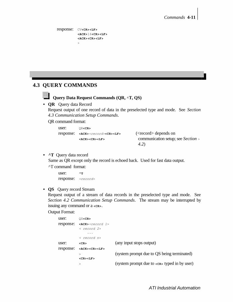
Query Data Request Commands (QR, ^T, QS)• QR Query data Record
Request output of one record of data in the preselected type and mode. See Section4.3 Communication Setup Commands.QR command format:
user: QR<CR>
response: <ACK><record><CR><LF> (<record> depends on<ACK><CR><LF> communication setup; see Section >
4.2)
• ^T Query data recordSame as QR except only the record is echoed back. Used for fast data output.^T command format:
user: ^T
response: <record>
• QS Query record StreamRequest output of a stream of data records in the preselected type and mode. SeeSection 4.2 Communication Setup Commands. The stream may be interrupted byissuing any command or a <CR>.Output Format:
user: QS<CR>
response: <ACK><record 1>< record 2> ···< record n>
user: <CR> (any input stops output)response: <ACK><CR><LF>
> (system prompt due to QS being terminated)<CR><LF>
> (system prompt due to <CR> typed in by user)
4-12 Commands
ATI Industrial Automation
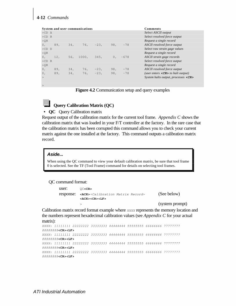
System and user communications Comments>CD A Select ASCII output>CD R Select resolved force output>QR Request a single record0, 89, 34, 76, -23, 98, -78 ASCII resolved force output>CD D Select raw strain gage values>QR Request a single record0, 12, 56, 1000, 345, 0, -678 ASCII strain gage records>CD R Select resolved force output>QR Request a single record0, 89, 34, 76, -23, 98, -78 ASCII resolved force output0, 89, 34, 76, -23, 98, -78 (user enters <CR> to halt output)> System halts output, processes <CR>
>
Figure 4.2 Communication setup and query examples
Query Calibration Matrix (QC)• QC Query Calibration matrix
Request output of the calibration matrix for the current tool frame. Appendix C shows thecalibration matrix that was loaded in your F/T controller at the factory. In the rare case thatthe calibration matrix has been corrupted this command allows you to check your currentmatrix against the one installed at the factory. This command outputs a calibration matrixrecord.
Aside...
When using the QC command to view your default calibration matrix, be sure that tool frame0 is selected. See the TF (Tool Frame) command for details on selecting tool frames.
QC command format:user: QC<CR>
response: <ACK><Calibration Matrix Record> (See below)<ACK><CR><LF>
> (system prompt)Calibration matrix record format example where XXXX represents the memory location andthe numbers represent hexadecimal calibration values (see Appendix C for your actualmatrix):XXXX: 11111111 22222222 33333333 44444444 55555555 66666666 7777777788888888<CR><LF>XXXX: 11111111 22222222 33333333 44444444 55555555 66666666 7777777788888888<CR><LF>XXXX: 11111111 22222222 33333333 44444444 55555555 66666666 7777777788888888<CR><LF>XXXX: 11111111 22222222 33333333 44444444 55555555 66666666 7777777788888888<CR><LF>

Commands 4-13
ATI Industrial Automation
Query F/T Peaks (QP)• QP Query Peaks
Request output of maximum and minimum values of resolved force/torque data collectedfrom SP command. The maximum values are preloaded with -9999 and the minimumvalues are preloaded with 9999. These preloaded values will be seen if the SPcommand was never enabled, after a hardware or software reset or after the SCcommand was issued. The QP command will not affect the collection of the maximum orminimum values while the SP command is enabled.QP command format:
user: QP<CR>
response: <ACK><Fxmax>, <Fymax>, <Fzmax>, <Txmax>, <Tymax>, <Tzmax><CR><LF><Fxmin>, <Fymin>, <Fzmin>, <Txmin>, <Tymin>, <Tzmin><CR><LF><ACK><CR><LF>
>
4.4 SENSOR COMMANDS
Sensor Biasing (SB, SU, SZ)The F/T controller has the capability of storing three different bias (zero) readings. Biasing isuseful for eliminating the effects of gravity (tool weight) or other forces acting on the end-effector. When a sensor bias is performed, the controller will read the forces and torquescurrently acting on the sensor and use these readings as a reference for future readings.Future readings will have this reference subtracted from them before they are transmitted.
Aside...
When biasing ensure the force and torque readings are steady-state. Biasing while thetransducer is vibrating, accelerating, or decelerating can provide a poor reference for yourapplication.
• SB Sensor BiasPerforms a sensor bias. Bias readings are stored in a LIFO (last-in-first-out) buffer. Ifan SB command is issued, the present bias reading (if any) is stored in the buffer. If anSU (Sensor Unbias) command is then issued, the previous bias reading is removed fromthe buffer and used as the current bias reading. Up to three levels of bias readings maybe stored in this manner.If an SB command is issued when the bias buffer is full, the bias replaces the most recentbias. This leaves the first two biases undisturbed.

4-14 Commands
ATI Industrial Automation
SB command format:user: SB<CR>
response: SB<CR><LF><ACK><ACK><CR><LF>
>
• SU Sensor UnbiasRemoves the last bias from the LIFO buffer and the previous bias, if any, is used as thecurrent bias reading.SU command format:
user: SU<CR>
response: SU<CR><LF><ACK><ACK><CR><LF>
>
• SZ Sensor Zero biasRemoves all previously stored biases. This command is executed on power-up or reset.SZ command format:
user: SZ<CR>
response: SZ<CR><LF><ACK><ACK><CR><LF>
>
Optional Sensor Temperature Compensation (ST b)Strain gage output can shift with change in temperature. This shift is in the form of a bias shiftand a gain shift.
Bias shift is the case where a change in temperature causes the output to change or shift by±X; where X is a function of temperature. The bias shift is normally small since the straingages are in a bridge that cancels most of the bias shift, but the bias shift may be moreapparent on high resolution sensors. You can eliminate the bias shift by performing asoftware sensor bias before measuring your load. An example of a bias shift: You bias thesensor and the F/T output should be reading near zero. The temperature shifts 10°F and theF/T output shows a 10 count reading in the Fz direction even though the load and orientationhave not changed. This error is described as a percentage of full scale; in this case, it wouldequal 10 counts divided by the rated load (in counts).

Commands 4-15
ATI Industrial Automation
Aside...
Bias shift can also occur from any change in induced strain of the outer wall of thetransducer, such as a change in interface plate screw tension.
Gain shift is the temperature-induced shift in force and torque output by Y% of the reading.An example of gain shift with no compensation: You bias the sensor and place a 500 countload in Fz which reads 500 counts. You take the load off. The temperature shifts 10°F andyou bias the sensor—which takes out the bias shift—and reapply the 500 count load. Theoutput changes to 507 counts, which is a change of (507-500)÷500 × 100% = 1.4% per10°F. A temperature compensation method is available to correct for the gain shift.
Force measurement from F/T sensor, counts
Forc
e ap
plied
to tr
ansd
ucer
, cou
nts
500
Output change due to bias shift
Output change due to gain shift
0 N
0 N
Normal output
500 507
7 count error due to gain shift
Figure 4.3 Example of how F/T output is effected by temperature changes
Figure 4.3 shows an example of how bias and gain shift affect the output of the F/T sensor.Bias shift changes the starting point, but not the slope. When you perform a software sensorbias you bring the starting point back to zero eliminating the bias shift. Gain shift changes theslope of the output. Temperature compensation will correct this gain shift. The gain shifterror can be corrected in the range of 0°C to 70°C.
Transducer operate at a temperature slightly higher than ambient due to self-heating of thestrain gages. This usually poses no problem since after the sensor is warmed up—around 5to 30 minutes—the sensor can be biased to remove any bias shift due to this self-heating. Aproblem may occur if additional mass that you want to measure is being placed directlyagainst the sensor since this would change the temperature of the sensor causing bias shift.High-resolution Nano and Mini sensors have the most bias shift due to additional mass beingplaced directly against them. You can prevent this bias shift by thermally insulating thetransducer from the mass—i.e. providing a ceramic or plastic plate between the load and thetransducer. When the transducer is mounted on a metal object, i.e. a robot arm, and a metaltool is mounted to the tool adaptor then the addition of a mass has little or no effect on thetemperature of the sensor.

4-16 Commands
ATI Industrial Automation
Note: with optional temperature compensation enabled(ST 1), it is possible to have straingage values reported outside of the -2048..2047 range.
• ST b Sensor Temperature compensation (Optional)b=0: disable temperature compensation of force/torque and gage data; default.b=1: enable temperature compensation of force/torque and gage data.The bias and gain shift are compensated as shown in the above paragraph. Performingthe SB (Sensor Bias) command as close as possible to the temperature at which you willbe measuring force/torque output will reduce bias shift and produce the most accurateoutput.ST b command format:
user: ST 1<CR>
response: ST 1<CR><LF><ACK><ACK><CR><LF>
>
The current state of sensor temperature compensation will be indicated when thevalue b is omitted.ST command format:
user: ST<CR>
response: ST<CR><LF><ACK>Temperature compensation enabled<CR><LF><ACK><CR><LF>
>
Sensor Peaks (SP b, SC)The two commands below work with the QP (Query Peaks) command to collect and clearthe maximum and minimum F/T values.• SP b Sensor Peaks
b=1: Enable collection of force/torque maximum and minimum values.b=0: Disable collection of force/torque maximum and minimum values; default.When enabled maximum and minimum F/T values are collected until reset or thecommand is disabled. The maximum and minimum values collected are kept in a bufferuntil they are cleared by the SC command or a system reset occurs. Use the QPcommand to read the values stored in this buffer. You can examine this buffer with SPenabled or disabled.SP 1 command format:
user: SP 1<CR>
response: SP 1<CR><LF><ACK><ACK><CR><LF>
>
The current state of SP command will be transmitted when the value b is omitted.SP command format:
user: SP<CR>
response: SP<CR><LF>

Commands 4-17
ATI Industrial Automation
<ACK>Peak monitoring enabled<CR><LF><ACK><CR><LF>
>
• SC Sensor peaks ClearedLoads -9999 in the maximum values and 9999 in the minimum values. This command isexecuted on system reset. If the sensor peak monitoring is enabled and the SCcommand is issued then the buffer will be cleared and new minimum and maximum valueswill be collected (issuing the SC command does not disable peak monitoring).SC command format:
user: SC<CR>
response: SC<CR><LF><ACK><ACK><CR><LF>
>
Sensor Error Message (SM b)• SM b Sensor Monitoring
b=1: Enable sending error message if sensor error is occurring; default.b=0: Disable sending error message if sensor error is occurring.The sensor monitoring command only affects the transmission of an error message beingsent due to a sensor error. The error flag health line and health LED are not affected bythis command; see Section 4.2. The sensor error could occur due to saturation,disconnected transducer cable or broken transducer. This command is enabled bydefault. When the CF 3 command is issued the sensor error due to saturation isdisabled; see the CF command. While the SM command is enabled and a sensor erroris occurring an error message will repeat continuously until the error is corrected ordisabled.SM 0 command format:
user: SM 0<CR>
response: SM 0<CR><LF><ACK><ACK><CR><LF>
>
If a value for b is omitted the system will indicate the current state of the SMcommand.SM command format:
user: SM<CR>
response: SM<CR><LF><ACK>Sensor monitoring disabled<CR><LF><ACK><CR><LF>
>
Sensor Sampling Frequency (SF d)• SF d Sensor sampling Frequency
The sampling frequency sets the internal update rate of the controller and is set by thefactory for six-axis output (CV 3F) with the CF command set at 0 (default). If youchange the number of axis readings or use the CF command for faster output you will

4-18 Commands
ATI Industrial Automation
have to change the sampling frequency, d, to provide the optimum output speed. Youdo not need to change the sampling frequency if you do not need a faster speed.Use Table 6.1 to select the optimum sampling frequency value to use in the SFcommand.SF d command format:
user: SF 2818<CR>
response: SF 2818<CR><LF> (Sampling frequency changed to 2818 Hz)<ACK><ACK><CR><LF>
>
If a value for d is omitted the system will indicate the current state of the SFcommand.SF command format:
user: SF<CR>
response: SF<CR><LF><ACK>2818<CR><LF><ACK><CR><LF>
>
Sensor Averaging (SA d)• SA d Sensor Averaging
Performs a moving average of d samples of sensor data. This can be useful to reducethe effects of mechanical vibrations and inertia. The parameter d must be 0, 2, 4, 8, or16. A value of 0 disables the averaging function and is the default. The CF 1 commandalso disables this feature.SA d command format:
user: SA 4<CR>
response: SA 4<CR><LF><ACK><ACK><CR><LF>
>
If a value for d is omitted the system will indicate the current state of the SMcommand.SA command format:
user: SA<CR>
response: SA<CR><LF><ACK>Averaging filtering on Filter = 4<CR><LF><ACK><CR><LF>
>
Aside...
A moving average is performed as follows:1. Collect the number of records requested (2, 4, 8, or 16)2. Calculate the mean value of the collected records3. Output the calculated mean value4. Remove the oldest value collected and replace it with a new value5. Go to step 2 and continue

Commands 4-19
ATI Industrial Automation
4.5 DISCRETE I/O COMMANDSSee Section 5 for a complete description of the discrete I/O. The commands shown in thissection are issued through the serial port and involve the use of the discrete I/O.
I/O Verification (ID, OD h)The following commands are useful for verifying proper discrete I/O connection. SeeSection 5 for pin-out and electrical specifications.
• ID Input DiscreteReads and displays the state of all discrete input lines. When the ID command is issued,seven characters representing the status of the input lines are transmitted.ID command format:
user: ID<CR>
response: ID<CR><LF><ACK><I3><I2><I1><I0><sp><M><B><CR><LF><ACK><CR><LF>
>
<I3> = Input bit 3, where 1 is on and 0 is off<I2> = Input bit 2<I1> = Input bit 1<I0> = Input bit 0<M> = Monitor input<B> = Bias input
System and user communications Comments>ID Request discrete inputs0100 10 Input bits 3, 1, and 0 are off
Monitor line is on, bias line is off>
Figure 4.4 Example of ID command
• OD h Output DiscreteSets the state of all discrete outputs and controller error LED as specified by thehexadecimal number h where the value of h is determined by:
bit function 0 Discrete I/O Output bit 01 Discrete I/O Output bit 12 Discrete I/O Output bit 23 Discrete I/O Output bit 34 Discrete I/O Status line

4-20 Commands
ATI Industrial Automation
5 Health LED on controller front6 Discrete I/O health line
OD h command format:user: OD 4A<CR>
response: OD 4A<CR><LF> (4A = 01001010 binary which<ACK><ACK><CR><LF> turns on discrete I/O output bit 1,> 3 and the discrete I/O health
line)Sending the command with the parameter h omitted is the same as sending “OD 0.”
Aside...
If the discrete I/O health line is off (not conducting) an error is occurring. Example errors areblown fuse, gage saturation, disconnected transducer, powered-down system, etc.The health line is on (conducting) when there is no error.
! Warning...
If the OD (Output Discrete) command is used to turn the off the health line be sure to turn itback on before using the health line to check for system errors.
Force Monitoring Commands (MC s, MD d, ML)
You can program the F/T controller to monitor force and torque thresholds. The thresholdsare programmed in statements called monitor conditions, using the MC command, andstored in non-volatile memory. The MD and ML commands are used to delete and list outthe stored monitor condition(s), respectively.
The discrete I/O is used to select the monitor condition(s) to be scanned and to output theprogrammed thresholds that have become valid, see Section 5.
The F/T controller can store a total of 32 monitor conditions.
! Warning...
New monitor conditions and tool frames are stored in run-time memory, which is volatile.Run-time memory is reloaded from permanent memory after system reset or power up. Usethe RS (Run Save) command to store any monitor condition or tool frame changes inpermanent memory. Changes will be lost if not stored in permanent memory. Keep a writtencopy of monitor conditions and tool frames in case of accidental erasure or system failure.
• MC s Monitor CreateCreates a monitor condition, s. The monitor condition consists of:
Input code/Threshold condition/Output code
Commands 4-21
ATI Industrial Automation
Input and output codes consist of a four-bit binary code (e.g. 0101) and work with theinput and output discrete I/O lines; see Section 5. Leading zeros are not required withthe output or input codes (i.e. 0101 is the same as 101). The input code identifies themonitor condition for scanning. The output code is used to identify which monitorconditions became true during scanning.
The threshold is a statement consisting of three components:a) Force or torque component: Fx, Fy, Fz, Tx, Ty, Tz.b) Greater or less than sign: >, <c) Threshold value in counts; see Appendix A.
A condition is considered true if the condition has been selected for scanning and thethreshold condition is satisfied by the measured forces and torques.MC s command format:
user: MC 1001/FZ>123/0101<CR>
response: MC 1001/FZ>123/0101<CR><LF><ACK><ACK><CR><LF>
>
where:MC is the command name typed at the prompt.1001 is the input code (send this code to the discrete I/O to turn this condition on).FZ>123 is the threshold condition (if Fz is greater than 123 this statement is true).0101 is the output code (sent to the discrete I/O if threshold condition is true).
As you can see, it is easy to use the monitor condition to look for a force or torqueabove or below a preset value. You can combine monitor conditions to check for avariety of complex conditions. An example follows:
Example: The force sensor is to check for Fz (force along the Z-axis) greater than 600counts, but less than 800 counts. The following monitor conditions should be written toimplement this:MC 1101/FZ<800/1000MC 1101/FZ>600/0001
The graph below shows the output code based on the value of Fz. You can determinewhen Fz is between 800 and 600 counts by sending an input code of 1101 and waitingfor an output code of 1001. An output code of 1000 indicates that Fz is below thelower limit, while an output code of 0001 indicates that Fz is above the upper limit.
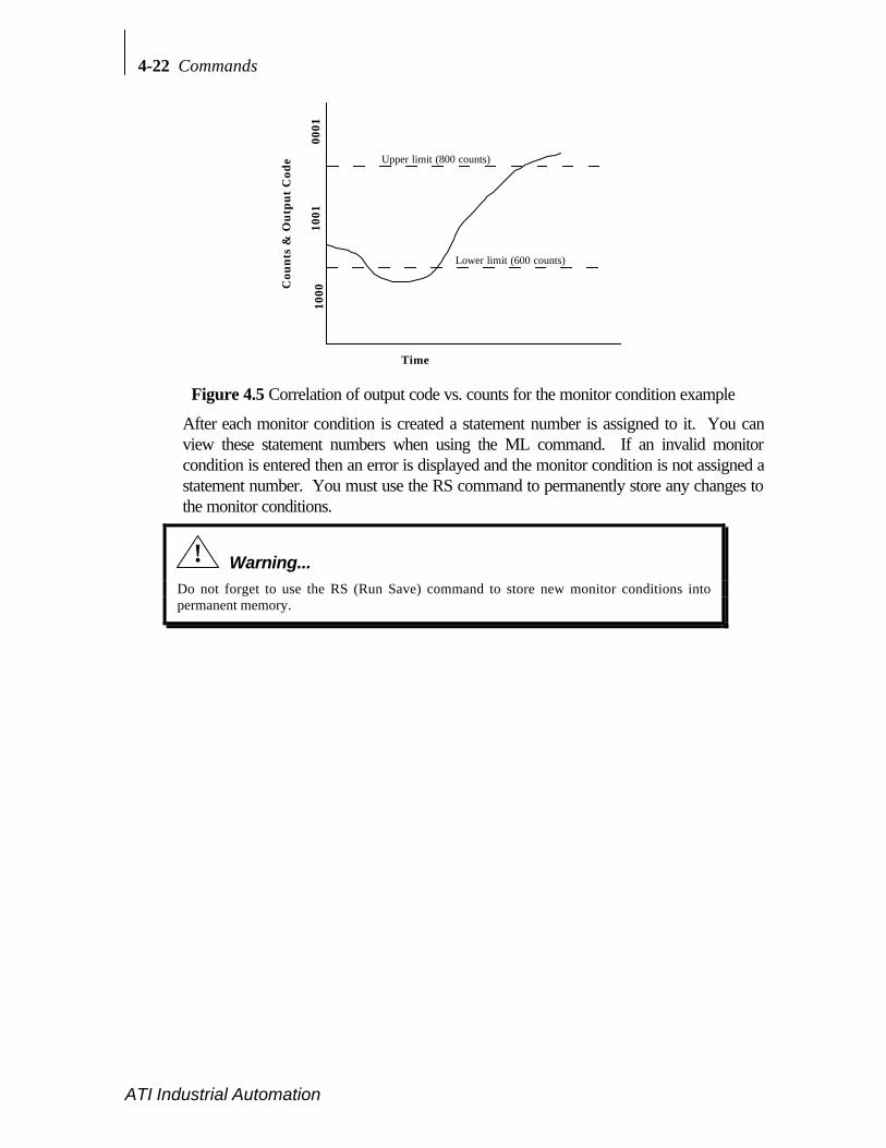
4-22 Commands
ATI Industrial Automation
Cou
nts
& O
utp
ut
Cod
e
Time
0001
1001
1000
Upper limit (800 counts)
Lower limit (600 counts)
Figure 4.5 Correlation of output code vs. counts for the monitor condition example
After each monitor condition is created a statement number is assigned to it. You canview these statement numbers when using the ML command. If an invalid monitorcondition is entered then an error is displayed and the monitor condition is not assigned astatement number. You must use the RS command to permanently store any changes tothe monitor conditions.
! Warning...
Do not forget to use the RS (Run Save) command to store new monitor conditions intopermanent memory.

Commands 4-23
ATI Industrial Automation
• MD d Monitor DeleteDeletes monitor condition where d is the statement number 1–32. Use the ML commandto find the statement number assigned to the monitor condition you wish to delete. MD *deletes all stored statements. If MD * is used then a confirmation statement is given toensure that all monitor statements are to be deleted.MD d command format:
user: MD 3<CR>
response: MD 3<CR><LF> (deletes monitor condition # 3)<ACK><ACK><CR><LF>
>
System and user communications Comments>MC 0001/Fy>245/0101 First construction of a monitorcondition
>mc 1/Fy>245/101 Second monitor condition. Statementis
equivalent to first statement>Mc 0111/Tx<789/1111 Third monitor condition. Note that
commands are not case sensitive>ML List all monitor conditions1) 0001/Fy>245/0101 2) 0001/Fy>245/01013) 0111/Tx<789/1111
>RS Permanently save monitor conditions
>MD * Delete all monitor conditionsDelete all monitor conditions (Y/N)? Y Query confirming deletion ofconditions
>ml List all monitor conditionsE129 No monitor conditions(s) Response when there are noconditions
>
Figure 4.6 Example of constructing, deleting, and listing monitor conditions
• ML Monitor ListLists all stored Monitor conditions (1 to 32), including their respective statementnumbers. If no monitor conditions are stored then an error message is given informingthat no monitor conditions exist.ML command format:
user: ML<CR>
response: ML<CR><LF>
<ACK>1)<monitor condition><sp>..<sp>2)<monitor condition>(the list continues until all the monitor conditions are shown)<ACK><CR><LF>
>
4-24 Commands
ATI Industrial Automation
4.6 TOOL FRAME COMMANDS
The default calibration matrix resolves forces and torque with respect to the transducerorigin. By using a tool transformation it is possible to directly measure the forces and torquesacting at some point other than the origin of the transducer. Tool transformations areparticularly useful when this point is chosen as the point of contact between the robotic end-effector (tool) and the object it is working on. The tool transformation may also rotate thecoordinate frame to align resolved force/torque components with the natural axes of the taskgeometry.
It is possible to have four calibration matrices stored in your F/T controller. The factoryinstalls the original calibration matrix which represents the calibration with the X, Y and Zorientation shown on the transducer drawings in Appendix B. This factory calibration matrixis stored as tool frame #0. You can change this calibrated orientation (rotation ortranslation) by changing the calibration matrix with the TC command. It is possible to deleteone of the tool frames by using the TD command. You must use the RS command to storeany tool frame changes into permanent memory or they will be lost with a software orhardware reset.
Aside...
Multiple transducers can be used with one controller. In some special cases more than onefactory calibration matrix can be placed into one controller. With this capability one to fourtransducers can be used with one controller, although not simultaneously. This allows youto switch from one matrix to another with the TF (Tool Frame) command. Call ATI IndustrialAutomation for more information.
Tool Frame Selection, Listing and Deleting (TF d, TL, TD d)• TF d Tool Frame selection
Select a tool frame, in run memory, d = 0, 1, 2 or 3. The original calibration matrix isstored in position 0. If you want the tool frame selected to start up after software orhardware reset send an RS command after selecting the tool frame. Issuing the TFcommand with no other value returns the current state.TF d command format:
user: TF 1<CR>
response: TF 1<CR><LF>
<ACK><ACK><CR><LF> (tool frame 1 selected)>
If a value for d is omitted the system will indicate the current state of the TFcommand.TF command format:
user: TF<CR>
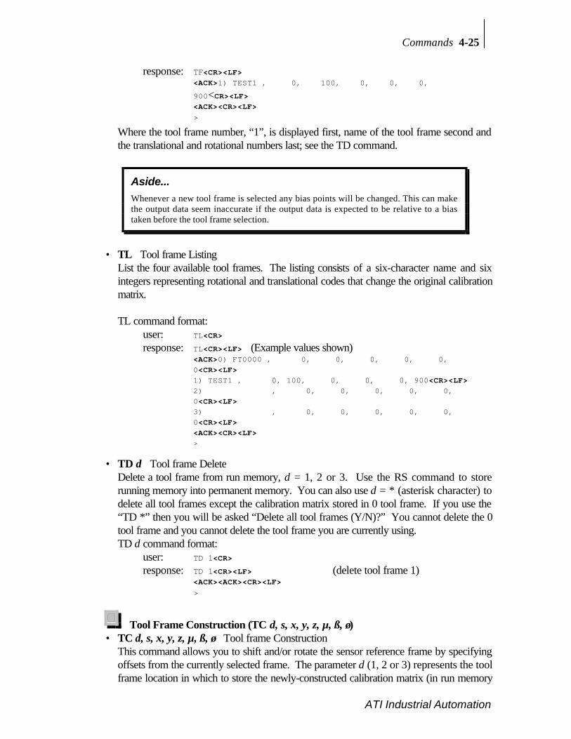
Commands 4-25
ATI Industrial Automation
response: TF<CR><LF><ACK>1) TEST1 , 0, 100, 0, 0, 0,
900<CR><LF><ACK><CR><LF>
>
Where the tool frame number, “1”, is displayed first, name of the tool frame second andthe translational and rotational numbers last; see the TD command.
Aside...
Whenever a new tool frame is selected any bias points will be changed. This can makethe output data seem inaccurate if the output data is expected to be relative to a biastaken before the tool frame selection.
• TL Tool frame ListingList the four available tool frames. The listing consists of a six-character name and sixintegers representing rotational and translational codes that change the original calibrationmatrix.
TL command format:user: TL<CR>
response: TL<CR><LF> (Example values shown)<ACK>0) FT0000 , 0, 0, 0, 0, 0,0<CR><LF>1) TEST1 , 0, 100, 0, 0, 0, 900<CR><LF>2) , 0, 0, 0, 0, 0,0<CR><LF>3) , 0, 0, 0, 0, 0,0<CR><LF><ACK><CR><LF>>
• TD d Tool frame DeleteDelete a tool frame from run memory, d = 1, 2 or 3. Use the RS command to storerunning memory into permanent memory. You can also use d = * (asterisk character) todelete all tool frames except the calibration matrix stored in 0 tool frame. If you use the“TD *” then you will be asked “Delete all tool frames (Y/N)?” You cannot delete the 0tool frame and you cannot delete the tool frame you are currently using.TD d command format:
user: TD 1<CR>
response: TD 1<CR><LF> (delete tool frame 1)<ACK><ACK><CR><LF>
>
Tool Frame Construction (TC d, s, x, y, z, µ, ß, ø)• TC d, s, x, y, z, µ, ß, ø Tool frame Construction
This command allows you to shift and/or rotate the sensor reference frame by specifyingoffsets from the currently selected frame. The parameter d (1, 2 or 3) represents the toolframe location in which to store the newly-constructed calibration matrix (in run memory

4-26 Commands
ATI Industrial Automation
use RS command to store into permanent memory). You cannot store into tool frameposition 0 since this holds the factory calibration and can only be changed at the factory.If you attempt to store a newly-constructed matrix in the tool frame position 0 you willreceive an error message. You also cannot construct a new tool frame in the currentlyselected tool frame (i.e., if you want to construct a new calibration matrix for tool frame1, your current tool frame cannot be 1, but should be 0, 2 or 3 if defined). The newly-constructed tool frame is built from the currently selected tool frame.The string s is a one-to-six character name that is assigned to this tool frame.
The integers x, y, and z represent the translation distances along each of these axes. Toderive values for these numbers, divide the actual distance by the Tool Transform Factor.The Tool Transform Factor for your sensor calibration can be found in Appendix A. Forexample, to translate a metric Nano17's coordinate system by 0.8 mm, the value wouldbe (0.8 mm)/(0.05 mm/unit)=16 units.
The integers µ, ß, and ø represent 1/10 of a degree for rotation about X-, Y- and Z-axisrespectively (e.g. if ß = 100 then the coordinate system is rotated 10° about the Y-axis).In a tool transformation, the order of the rotations matters. The X-rotation occurs first,followed by rotation about Y (in its new orientation), then Z. Therefore, you MUSTexpress your rotations in this order. Use the right hand rule to find the positive andnegative rotation. Example of right hand rule: point your thumb along the positive axisyou are interested in rotating about and your fingers will roll about the positive rotationdirection.
Suppose we want to move the origin of our Gamma sensor (US units) -1 inch in the Xdirection and 6 inches in the Z direction. We also want to rotate -90 degrees about theX-axis, then 5.3 degrees about the Z-axis. We will store this in tool frame 2 and name itSTORE2.TC d, s, x, y, z, µ, ß, ø command format:
User: TC 2, STORE2, -100, 0, 600, -900, 0, 53<CR>response: TC 2, STORE2, -100, 0, 600, -900, 0, 53<CR><LF>
<ACK><ACK><CR><LF> >
! Warning...
Do not forget to use the RS (Run Save) command to store new tool frames into permanentmemory.
4.7 OTHER F/T COMMANDS

Commands 4-27
ATI Industrial Automation
Zip Macro Create Start-up Buffer (ZC 0, "s")• ZC 0, "s" Zip macro Create
Creates a buffer of commands, s, which are sequentially executed at system power-up orreset. Commands must be separated by a semicolon, “;”. The buffer is stored inpermanent memory (you do not need to use the RS command).ZC 0,"s" command format:
user: ZC 0, "CD A; SA 4;SB"<CR>
response: ZC 0, "CD A; SA 4;SB"<CR><LF><ACK><ACK><CR><LF>
>
If the ZC command is used without any parameters the start-up buffer is displayed.ZC command format:
user: ZC<CR>
response: ZC<CR><LF><ACK>CD A; SA 4;SB;<CR><LF><ACK><CR><LF>
>
To clear the buffer simply enter an empty command string: ZC 0,""<CR>
Warm Start (^W)• ^W (Control-W) Warm start
Performs a system reset and is identical to pressing the reset button. A header messagewill appear on start-up which consist of:1) Rated force and torque in force units (pounds, Newtons, etc.) and torque units
(pound-inches, Newton-meters, etc.). Some special calibrations have different forceand torque units.
2) Number of counts per force units and torque within parentheses.3) Serial number (SN).4) Force and torque vectors displayed. The hex value 3F represents that all six
components of the F/T vector are displayed. See the CV command.5) Software version.6) Copyright notice.
Example Gamma transducer calibrated as a 15/50 with 15 lb rated force and 50 lb-inrated torque, 80 counts per pound and 80 counts per pound-inch, SN FT0000, all sixcomponents of the F/T vector and software version 4.25:user enters: ^W<CR><XON><LF><XON><CR><LF>F15/T50(80/80) SN FT0000-3F Version 4.25<CR><LF>Copyright(c) 1990, 1991, 1992 by Assurance Technologies, Inc., Garner,NC<CR><LF>All Rights Reserved<CR><LF>>
Filter Clock (FC d)
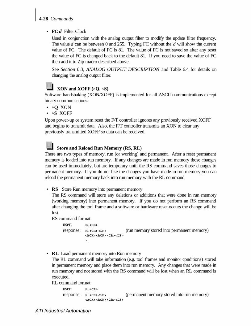
4-28 Commands
ATI Industrial Automation
• FC d Filter ClockUsed in conjunction with the analog output filter to modify the update filter frequency.The value d can be between 0 and 255. Typing FC without the d will show the currentvalue of FC. The default of FC is 81. The value of FC is not saved so after any resetthe value of FC is changed back to the default 81. If you need to save the value of FCthen add it to Zip macro described above.
See Section 6.3, ANALOG OUTPUT DESCRIPTION and Table 6.4 for details onchanging the analog output filter.
XON and XOFF (^Q, ^S)Software handshaking (XON/XOFF) is implemented for all ASCII communications exceptbinary communications.• ^Q XON• ^S XOFF
Upon power-up or system reset the F/T controller ignores any previously received XOFFand begins to transmit data. Also, the F/T controller transmits an XON to clear anypreviously transmitted XOFF so data can be received.
Store and Reload Run Memory (RS, RL)There are two types of memory, run (or working) and permanent. After a reset permanentmemory is loaded into run memory. If any changes are made in run memory those changescan be used immediately, but are temporary until the RS command saves those changes topermanent memory. If you do not like the changes you have made in run memory you canreload the permanent memory back into run memory with the RL command.
• RS Store Run memory into permanent memoryThe RS command will store any deletions or additions that were done in run memory(working memory) into permanent memory. If you do not perform an RS commandafter changing the tool frame and a software or hardware reset occurs the change will belost.RS command format:
user: RS<CR>
response: RS<CR><LF> (run memory stored into permanent memory)<ACK><ACK><CR><LF>
>
• RL Load permanent memory into Run memoryThe RL command will take information (e.g. tool frames and monitor conditions) storedin permanent memory and place them into run memory. Any changes that were made inrun memory and not stored with the RS command will be lost when an RL command isexecuted.RL command format:
user: RL<CR>
response: RL<CR><LF> (permanent memory stored into run memory)<ACK><ACK><CR><LF>
Commands 4-29
ATI Industrial Automation
>
! Warning...
New monitor conditions and tool frames are stored in run-time memory, which is volatile.Run-time memory is reloaded from permanent memory after system reset or power up. Usethe RS (Run Save) command to store any monitor condition or tool frame changes inpermanent memory. Changes will be lost if not stored in permanent memory. Keep a writtencopy of monitor conditions and tool frames in case of accidental erasure or system failure.
hhhh hhhh hhhh
This page intentionally left blank.

5 Serial and
Discrete I/O
Section Page
5.1 SERIAL AND DISCRETE I/O PIN ASSIGNMENTS ................................... 5-2Serial I/O Pin-out ............................................................................................ 5-2Discrete I/O Pin-out ........................................................................................ 5-3
5.2 SERIAL I/O DESCRIPTION ........................................................................... 5-45.3 DISCRETE I/O DESCRIPTION...................................................................... 5-4
Typical Input and Output Connections .......................................................... 5-4Monitor Conditions ......................................................................................... 5-4Discrete I/O Timing Diagram......................................................................... 5-6Health Line...................................................................................................... 5-7Bias Line ......................................................................................................... 5-8
5.4 SERIAL AND DISCRETE I/O ELECTRICALCHARACTERISTICS.............................................................................................. 5-8
Serial I/O Electrical Characteristics .............................................................. 5-8Discrete I/O Electrical Characteristics.......................................................... 5-8

5-2 Serial and Discrete I/O
ATI Industrial Automation
5.1 SERIAL AND DISCRETE I/O PIN ASSIGNMENTS
Serial I/O Pin-outThe RS-232 serial port is a female 9 pin D-subminiature connector using a 3-wirecommunication.
Pin Signal1 N/C
2 Receive
3 Transmit
4 Reserved
5 Ground
6 N/C
7 N/C
8 N/C
9 N/CN/C = Not Connected
Table 5.1 RS-232 serial I/O connector pin assignments
5
9
4
8
3
7
2
6
1
Figure 5.1 Serial I/O port as viewed from rear of F/T controller
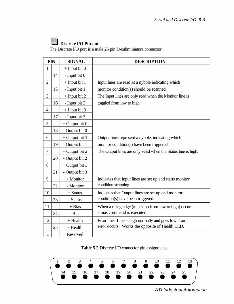
Serial and Discrete I/O 5-3
ATI Industrial Automation
Discrete I/O Pin-outThe Discrete I/O port is a male 25 pin D-subminiature connector.
PIN SIGNAL DESCRIPTION1 + Input bit 0
14 - Input bit 02 + Input bit 1 Input lines are read as a nybble indicating which
15 - Input bit 1 monitor condition(s) should be scanned.3 + Input bit 2 The Input lines are only read when the Monitor line is
16 - Input bit 2 toggled from low to high.4 + Input bit 3
17 - Input bit 35 + Output bit 0
18 - Output bit 06 + Output bit 1 Output lines represent a nybble, indicating which
19 - Output bit 1 monitor condition(s) have been triggered.7 + Output bit 2 The Output lines are only valid when the Status line is high.
20 - Output bit 28 + Output bit 3
21 - Output bit 39 + Monitor Indicates that Input lines are set up and starts monitor
22 - Monitor condition scanning.
10 + Status Indicates that Output lines are set up and monitor23 - Status condition(s) have been triggered.
11 + Bias When a rising edge (transition from low to high) occurs24 - Bias a bias command is executed.
12 + Health Error line. Line is high normally and goes low if an25 - Health error occurs. Works the opposite of Health LED.
13 Reserved
Table 5.2 Discrete I/O connector pin assignments
1
14
2
15
3
16
4
17
5
18
6
19
7
20
8
21
9
22
10
23
11
24
12
25
13
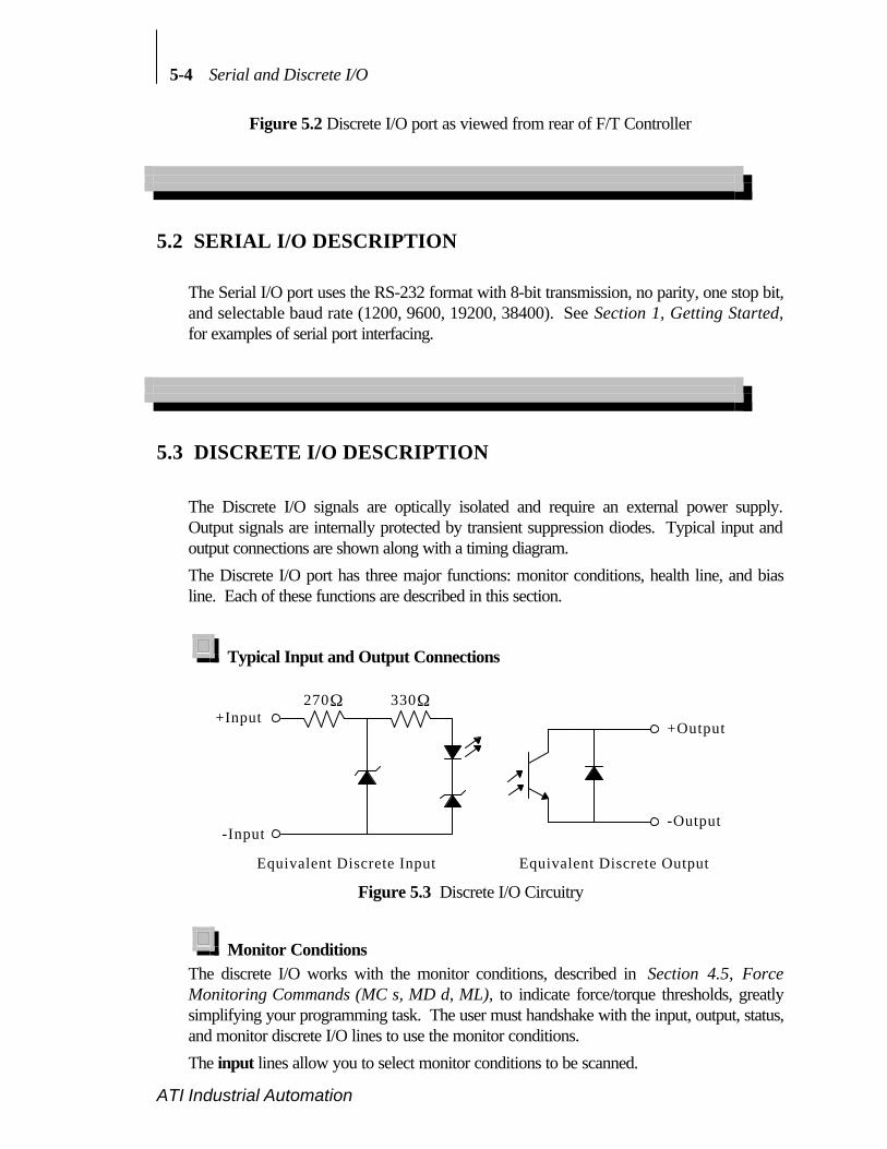
5-4 Serial and Discrete I/O
ATI Industrial Automation
Figure 5.2 Discrete I/O port as viewed from rear of F/T Controller
5.2 SERIAL I/O DESCRIPTION
The Serial I/O port uses the RS-232 format with 8-bit transmission, no parity, one stop bit,and selectable baud rate (1200, 9600, 19200, 38400). See Section 1, Getting Started,for examples of serial port interfacing.
5.3 DISCRETE I/O DESCRIPTION
The Discrete I/O signals are optically isolated and require an external power supply.Output signals are internally protected by transient suppression diodes. Typical input andoutput connections are shown along with a timing diagram.
The Discrete I/O port has three major functions: monitor conditions, health line, and biasline. Each of these functions are described in this section.
Typical Input and Output Connections
270Ω 330Ω
-Input
+Input+Output
-Output
Equivalent Discrete Input Equivalent Discrete Output
Figure 5.3 Discrete I/O Circuitry
Monitor ConditionsThe discrete I/O works with the monitor conditions, described in Section 4.5, ForceMonitoring Commands (MC s, MD d, ML), to indicate force/torque thresholds, greatlysimplifying your programming task. The user must handshake with the input, output, status,and monitor discrete I/O lines to use the monitor conditions.
The input lines allow you to select monitor conditions to be scanned.

Serial and Discrete I/O 5-5
ATI Industrial Automation
The output lines indicate which monitor conditions have been triggered.
The monitor line instructs the F/T controller to scan the monitor conditions whose inputcode matches the Input lines.
The status line indicates that one or more monitor conditions have been triggered. Whenthe status line is asserted, a valid output code is on the output lines.To use the discrete I/O to scan for triggered monitor conditions do the following:
a) Enter monitor conditions using the software commands shown in Section 4.6.b) Place the input code of the monitor condition(s) you would like to have scanned
onto the input lines. See pin-out shown in Table 5.2.c) Bring the monitor line low if it is high.d) Wait for the status line to go low if it is high.e) Bring the monitor line high to indicate a valid input code is present. The input lines
are read after the rising edge of the monitor line is seen. See the timing diagram inFigure 5.4.
f) While the monitor line is high the selected monitor condition(s) are scanned for trueconditions. If a true condition occurs then the output code of that monitor conditionis presented to the output lines of the discrete I/O. If more than one output code istriggered then the F/T system outputs the logical OR of the triggered output codes.Example: Three output codes are triggered: 0010, 1000, 1100
00101000
∨ 11001110
(“∨” is the mathematical symbol for logical OR.) The code 1110 is sent to thediscrete output lines.
g) Once the output code is presented the system will assert the status line. Monitorconditions are no longer scanned as long as the status line is asserted.
h) The monitor line should be lowered after the output code is read.i) When the F/T system detects the monitor line lowered, it will remove the output
code from the discrete I/O port and lower the status line.j) Repeat steps a through h as often as you like.

5-6 Serial and Discrete I/O
ATI Industrial Automation
Discrete I/O Timing Diagram
DiscreteInput
DiscreteOutput
t i p w tdis t dih
t s a
td o s
t m r
t s r
t d s a
t m a
SensorData
MonitorInput
StatusOutput
t d o h
Figure 5.4 Discrete I/O timing diagram

Serial and Discrete I/O 5-7
ATI Industrial Automation
Symbol Parameter Notes Min Max Units
Tdis Discrete input setup Unaffected by Commands 0.00 ms
Tsa Monitor assert to status 1 vector enabled, 1 condition 2.00 3.75 ms
assert 6 vectors, 1 condition, averagingenabled
2.60 4.20 ms
6 vectors, 8 conditions, averagingenabled
2.70 4.60 ms
6 vectors, 32 conditions, averagingenabled
3.20 4.85 ms
Tdsa Sensor data to statusassert
1 vector enabled, 1 condition 0.65 2.15 ms
6 vectors, 1 condition, averagingenabled
1.00 2.25 ms
6 vectors, 8 conditions, averagingenabled
1.30 2.40 ms
6 vectors, 32 conditions, averagingenabled
1.80 2.95 ms
Tdos Discrete output setup Unaffected by Commands 0.55 0.95 ms
Tmr Status assert to monitorrelease
Unaffected by Commands 0.00 ms
Tdih Discrete input hold Unaffected by Commands 0.00 ms
Tsr Monitor release tostatus
1 vector enabled, 1 condition 1.30 2.30 ms
release 6 vectors, 1 condition, averagingenabled
1.30 2.95 ms
6 vectors, 8 conditions, averagingenabled
1.30 2.95 ms
6 vectors, 32 conditions, averagingenabled
1.30 2.95 ms
Tdoh Discrete output hold Unaffected by Commands 1.15 2.45 ms
Tma Status release tomonitor assert
Unaffected by Commands 0.00 ms
Tipw Ignored pulse width Unaffected by Commands 0.00 0.55 ms
Notes:• Signals are measured at the discrete I/O connector.• Communications port transmissions will slow down response times.• ^S/^Q handshaking on serial port can stop discrete I/O processing.
Table 5.3 Discrete I/O timing characteristics
Health LineThis line is used in conjunction with the health LED on the front of the F/T Controller.During F/T system normal operating state the health line is “on” and front panel Error LEDis off. If an error occurs in the F/T system, such as saturation, the health line is turned offand the front panel Error LED is turned on.

5-8 Serial and Discrete I/O
ATI Industrial Automation
Bias LineThis line is used to bias the F/T system and works the same as sending the command SB.A bias is taken on a low-to-high transition. There is no provision for unbiasing through thediscrete I/O.
A common application would be to bias the resolved force vector just prior to examiningthe forces and torques. Biasing eliminates drift and gives an accurate force/torque data ofthe forces applied by the application.
5.4 SERIAL AND DISCRETE I/O ELECTRICAL CHARACTERISTICS
Serial I/O Electrical CharacteristicsAbsolute Maximum Ratings
Input lines (RS-232 pins 2 and 4)
Vin = ±30V
Output lines short circuit duration (RS-232 pin 3)
t = ∞
Parameter Conditions Min. Typ. Max. UnitsOutput Voltage Swing ±5 ±9 VOutput Short Circuit Current ±10 mAInput Voltage Range -30 +30 VInput Voltage Threshold Low TA = 25°C 0.8 1.2 V
Input Voltage Threshold High TA = 25°C 1.7 2.4 V
Input Hysteresis 0.2 0.5 1.0 VInput Resistance 3 5 7 kΩ
Table 5.4 Serial I/O electrical characteristics
Discrete I/O Electrical CharacteristicsAbsolute Maximum Ratings
Input lines (Input bits 0, 1, 2, 3, Monitor, and Bias)
Vin = -24.0V to 26.5V
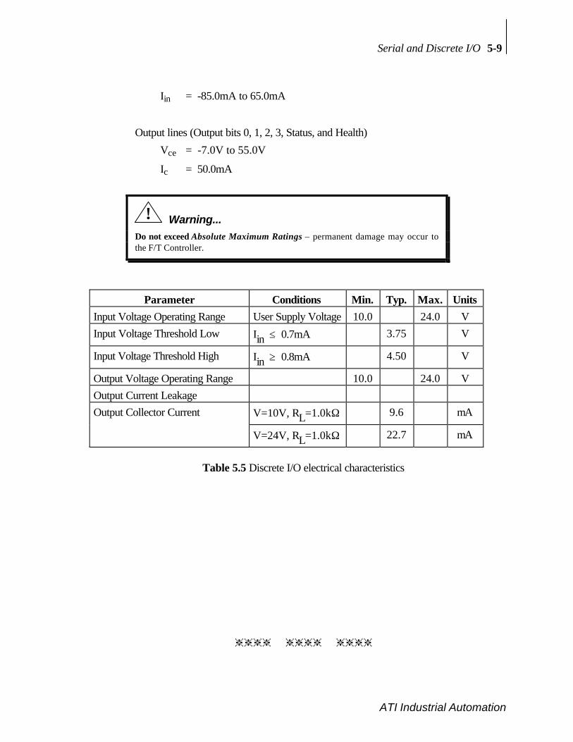
Serial and Discrete I/O 5-9
ATI Industrial Automation
Iin = -85.0mA to 65.0mA
Output lines (Output bits 0, 1, 2, 3, Status, and Health)
Vce = -7.0V to 55.0V
Ic = 50.0mA
! Warning...
Do not exceed Absolute Maximum Ratings – permanent damage may occur tothe F/T Controller.
Parameter Conditions Min. Typ. Max. UnitsInput Voltage Operating Range User Supply Voltage 10.0 24.0 VInput Voltage Threshold Low Iin ≤ 0.7mA 3.75 V
Input Voltage Threshold High Iin ≥ 0.8mA 4.50 V
Output Voltage Operating Range 10.0 24.0 VOutput Current LeakageOutput Collector Current V=10V, RL=1.0kΩ 9.6 mA
V=24V, RL=1.0kΩ 22.7 mA
Table 5.5 Discrete I/O electrical characteristics
hhhh hhhh hhhh

5-10 Serial and Discrete I/O
ATI Industrial Automation
This page intentionally left blank.
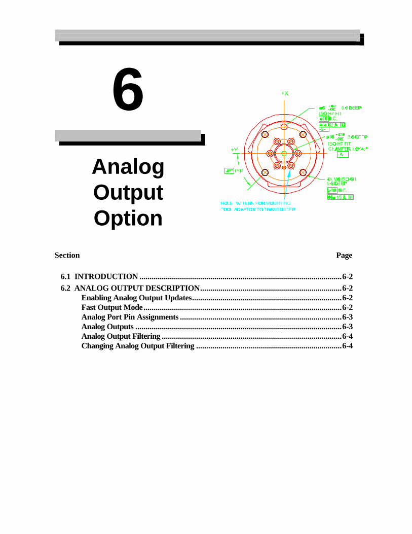
6 AnalogOutputOption
Section Page
6.1 INTRODUCTION ....................................................................................................6-26.2 ANALOG OUTPUT DESCRIPTION......................................................................6-2
Enabling Analog Output Updates..........................................................................6-2Fast Output Mode..................................................................................................6-2Analog Port Pin Assignments ................................................................................6-3Analog Outputs ......................................................................................................6-3Analog Output Filtering .........................................................................................6-4Changing Analog Output Filtering ........................................................................6-4

6-2 Optional Analog
ATI Industrial Automation
6.1 INTRODUCTION
The Analog Interface Board allows the user to communicate with the controller at fasterspeeds than the standard RS-232 serial port. The six outputs of the analog interface canrepresent either F/T values or strain gage data.
Aside…
Fz Analog Output NOTE: The Fz analog output will not have the maximumvoltage output at the rated Fz range. The Fz analog output range is the same asthe Fx and Fy range. For example: The Gamma US-30-100 F/T system iscalibrated for the Fx and Fy ranges to be 30lb and the Fz will measure up to100lb, but the Fz analog output will have a maximum output voltage reading at30lb just like Fx and Fy, not at the specified 100lb range.
6.2 ANALOG OUTPUT DESCRIPTIONThe analog output port provides analog voltages representing sensor data and an analogupdate signal for advanced users. The analog outputs are the analog representation of theQS command. The 20-pin analog port connector provides ±5V (optional ±10V availableupon request) signals for each of the six possible outputs. See Figure 6.1 and Table 6.2 foranalog port pinouts. To reduce potential analog noise, we recommend using twisted-pairribbon cable in your analog port connections.
Enabling Analog Output UpdatesThe CA b command controls the updating of the analog outputs. Entering CA 1 starts theupdating and CA 0 stops the updating [see Section 4.2].
Aside...
The analog output command defaults to “CA 0” on system initialization, regardless of previoussettings. Therefore it is necessary to include an “CA 1” command in the system startup buffer, ZipMacro 0, if you wish to automatically enable analog outputs.
Fast Output ModeThe normal update rate of the system is 752 Hz, but by using the CF command (seeSection 4.2) you can increase the update rate. You can also increase the update rate byreducing the number of F/T axes output (use the CV command; see Section 4.2). If youuse the CF or CV command you can use the SF command to select the optimum samplingfrequency to give you the fastest update rate.
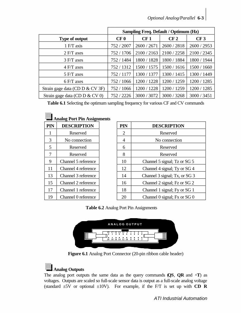
Optional Analog/Parallel 6-3
ATI Industrial Automation
Sampling Freq. Default / Optimum (Hz)Type of output CF 0 CF 1 CF 2 CF 3
1 F/T axis 752 / 2007 2600 / 2671 2600 / 2818 2600 / 29532 F/T axes 752 / 1706 2100 / 2163 2100 / 2258 2100 / 23453 F/T axes 752 / 1484 1800 / 1828 1800 / 1884 1800 / 19444 F/T axes 752 / 1312 1500 / 1575 1500 / 1616 1500 / 16605 F/T axes 752 / 1177 1300 / 1377 1300 / 1415 1300 / 14496 F/T axes 752 / 1066 1200 / 1228 1200 / 1259 1200 / 1285
Strain gage data (CD D & CV 3F) 752 / 1066 1200 / 1228 1200 / 1259 1200 / 1285Strain gage data (CD D & CV 0) 752 / 2226 3000 / 3072 3000 / 3268 3000 / 3451
Table 6.1 Selecting the optimum sampling frequency for various CF and CV commands
Analog Port Pin AssignmentsPIN DESCRIPTION PIN DESCRIPTION
1 Reserved 2 Reserved3 No connection 4 No connection5 Reserved 6 Reserved7 Reserved 8 Reserved9 Channel 5 reference 10 Channel 5 signal; Tz or SG 511 Channel 4 reference 12 Channel 4 signal; Ty or SG 413 Channel 3 reference 14 Channel 3 signal; Tx, or SG 315 Channel 2 reference 16 Channel 2 signal; Fz or SG 217 Channel 1 reference 18 Channel 1 signal; Fy or SG 119 Channel 0 reference 20 Channel 0 signal; Fx or SG 0
Table 6.2 Analog Port Pin Assignments
20 18 16 14 12 10 8 6 4 2
19 17 15 13 11 9 7 5 3 1
A N A L O G O U T P U T
Figure 6.1 Analog Port Connector (20-pin ribbon cable header)
Analog OutputsThe analog port outputs the same data as the query commands (QS, QR and ^T) asvoltages. Outputs are scaled so full-scale sensor data is output as a full-scale analog voltage(standard ±5V or optional ±10V). For example, if the F/T is set up with CD R

6-4 Optional Analog
ATI Industrial Automation
(communicate data resolved) command and CA 1 (communicate analog enabled) commandand a rated load is applied to the Fx axis, then the analog output “Channel 0” will be at full-scale voltage.
Analog Output FilteringAs with any digital-to-analog conversion, the analog signals need to be filtered to removeunwanted high-frequency steps (discontinuities) that occur when the output is updated. Ifthese steps are not removed and the user digitizes during a transition, there is a possibilitythe acquired sample would be invalid. To reduce the likelihood of a bad sample the outputsare filtered to remove the steps. The analog board output filters are factory set for a 1000Hz update rate.
Changing Analog Output FilteringThe analog filters can be matched to one of two update rates. The first rate is the default of1000 Hz. The second update rate, factory set to 2500 Hz, is selected by changing jumperson the analog printed circuit board and using the FC d command. Table 6.3 describes thechanges necessary under Filter Selection. All output channels must have the same filterselection.
Filter Description 1000 Hz 2500 HzType Butterworth ButterworthOrder 5th 5thAv @ 1/2 Update Frequency -52dB -40dBFilter Clock command FC 81 FC 26Jumper settings:J1, J2, J5, J6, J9, J10 1.0Khz 2.5Khz
Table 6.3 Analog Filter Characteristics
Aside...
The filter clock defaults to “FC 81” on system initialization, regardless of previous settings.Therefore it is necessary to include an “FC d” command in the system startup buffer, Zip Macro 0,if the default filter is not used.

7 Trouble-
Shooting
Guide
Section Page
7.1 INTRODUCTION ...................................................................................................7-27.2 QUESTIONS AND ANSWERS..............................................................................7-3
Communications ....................................................................................................7-3Errors with force and torque readings .................................................................7-4
7.3 ERROR MESSAGES..............................................................................................7-5

7-2 Problem Solving Guide
ATI Industrial Automation
7.1 INTRODUCTION
The answers to some questions and problems that might arise when setting up and using theF/T system are included in this section. The question or problem is listed followed by theprobable answer or solution. The questions/problems are categorized for easy reference.
The information in this section should answer many questions that might arise in the field.Customer service is available to users that may have problems that the manual cannot solveor questions that cannot be answered:
ATI Industrial AutomationCustomer ServicePinnacle Park1031 Goodworth DriveApex, NC 27502 USA
Phone: +1.919.772.0115Fax: +1.919.772.8259E-mail: [email protected]
Aside...
Please read the manual before calling customer service. Before calling, have the followinginformation available:1. Serial number(s)2. Transducer type, e.g. Nano-17, Gamma, Theta3. Calibration, e.g. /US-15-50, /SI-130-104. Accurate and complete description of the question or problem.5. Controller revision. This is output in the initialization header message of the
controller.
If possible be near the F/T system when talking with an ATI Industrial Automationcustomer service representative.
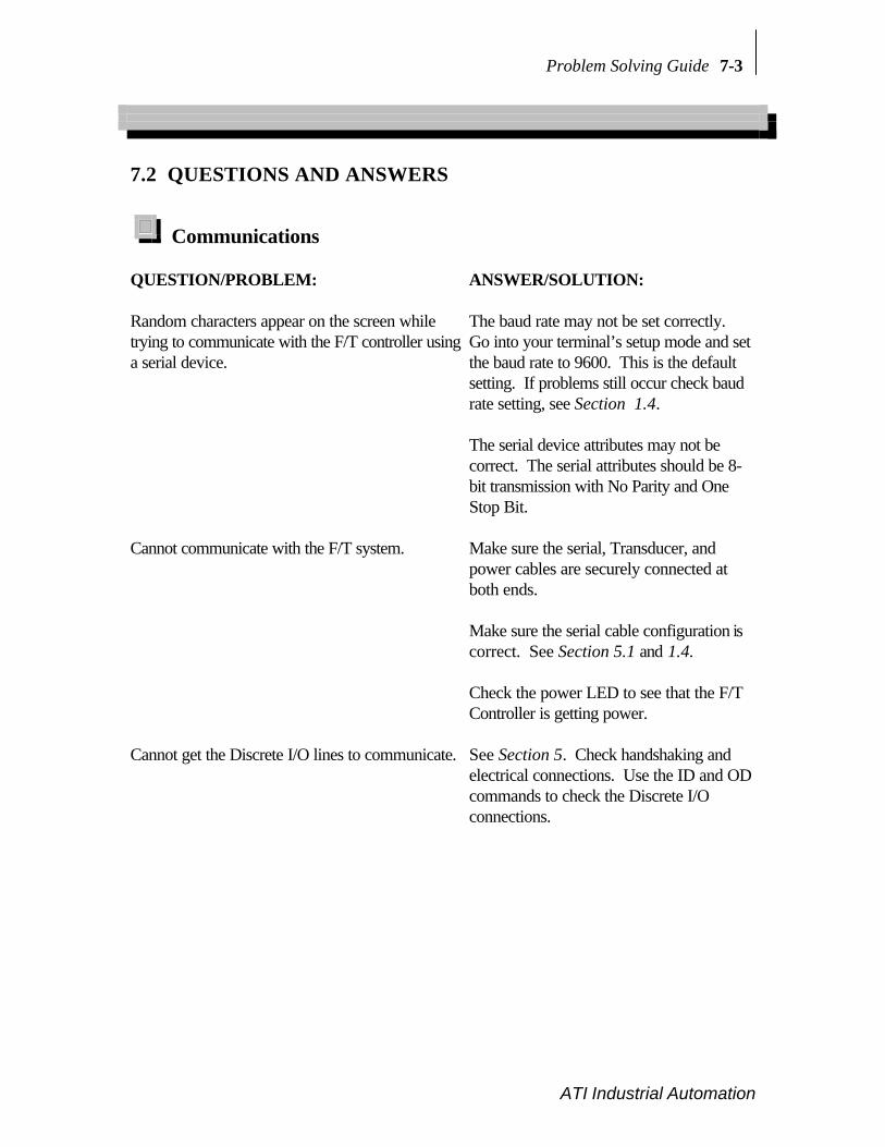
Problem Solving Guide 7-3
ATI Industrial Automation
7.2 QUESTIONS AND ANSWERS
Communications
QUESTION/PROBLEM: ANSWER/SOLUTION:
Random characters appear on the screen whiletrying to communicate with the F/T controller usinga serial device.
The baud rate may not be set correctly.Go into your terminal’s setup mode and setthe baud rate to 9600. This is the defaultsetting. If problems still occur check baudrate setting, see Section 1.4.
The serial device attributes may not becorrect. The serial attributes should be 8-bit transmission with No Parity and OneStop Bit.
Cannot communicate with the F/T system. Make sure the serial, Transducer, andpower cables are securely connected atboth ends.
Make sure the serial cable configuration iscorrect. See Section 5.1 and 1.4.
Check the power LED to see that the F/TController is getting power.
Cannot get the Discrete I/O lines to communicate. See Section 5. Check handshaking andelectrical connections. Use the ID and ODcommands to check the Discrete I/Oconnections.

7-4 Problem Solving Guide
ATI Industrial Automation
Errors with force and torque readingsBad data from the transducer’s strain gages can cause errors in force/torque readings. Theseerrors can result in problems with threshold monitoring, sensor biasing and accuracy. Listedbelow are the basic conditions of bad data. Use this to troubleshoot your problem. In mostcases, problems can be seen better while transmitting raw strain gage data (command CD D) toa terminal.
QUESTION/PROBLEM: ANSWER/SOLUTION:
Saturation When the data from a raw decimal strain gage reads -2048 or2047, that gage is saturated. This generates a saturation errormessage and causes the red LED to turn on when sensor monitoris enabled, sets the health line low on the discrete I/O and sets theoverload bit high. Saturation occurs if the sensor is loadedbeyond its rated maximum, or in the event of an electrical failurewithin the system. The error message will repeat until thesaturation error stops. If the “SM 0” command was sent then anerror message will not occur, but the LED, health line andoverload byte will work.
Note: with optional temperature compensation enabled (TC 1), itis possible to have strain gage values reported outside of the -2048..2047 range.
Noise Jumps in raw strain gage readings (with sensor unloaded) greaterthan 5 counts is considered abnormal. Noise can be caused bymechanical vibrations and electrical disturbances, possibly from apoor ground. It can also indicate component failure within thesystem.
Drift After a load is removed or applied the raw gage reading does notstabilize but continues to increase or decrease. This may beobserved more easily in resolved data mode using the biascommand, SB. Drift is caused by temperature change,mechanical coupling or internal failure. Mechanical coupling iscaused when a connection is made between the tool plate and thesensor body (i.e. plastic filings between the tool adaptor plate andthe transducer body). Some mechanical coupling is common,such as hoses and wires attached to a tool.
Hysteresis When the sensor is loaded and then unloaded, gage readings donot return quickly and completely to their original readings.Hysteresis is caused by mechanical coupling (explained in driftsection) or internal failure.

Problem Solving Guide 7-5
ATI Industrial Automation
7.3 ERROR MESSAGES
When an error occurs a message is sent over the serial. The error message is made of thefollowing items:
a) NAK as the first byte.b) A capital “E” follows.c) An error number follows and consists of a three number sequence in ASCII mode,
but one byte in Binary mode.d) An error description no longer than 80 bytes follows the error number.e) A carriage return and line feed follows the error description and marks the end of the
error message. A line feed will not be sent if it has been disabled with the CLcommand.
f) Another carriage return and line feed follow.g) The prompt is the last item shown.
System and user communications Comments>L ìLî is entered by mistakeE114 Illegal command Error message is displayed. The
<NAK> is not displayed. <CR><LF>> are sent followed by ì>î prompt.
Figure 7.1 Error message example
Error # Error description Comment
100 thru 107 Gauge n saturation n represents last digit in error # (10n)
108 Input buffer overrun User is sending data too quickly
109 Output buffer overrun
110 Command too long
111 Output buffer failure
112 Illegal input port
113 Illegal output port
114 Illegal command
115 X-axis force saturation
116 Y-axis force saturation The rated load is exceeded in the axis
117 Z-axis force saturation shown
118 XYZ-axes torque saturation
119 Illegal monitor condition operand
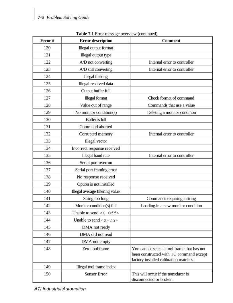
7-6 Problem Solving Guide
ATI Industrial Automation
Table 7.1 Error message overview (continued)Error # Error description Comment
120 Illegal output format
121 Illegal output type
122 A/D not converting Internal error to controller
123 A/D still converting Internal error to controller
124 Illegal filtering
125 Illegal resolved data
126 Output buffer full
127 Illegal format Check format of command
128 Value out of range Commands that use a value
129 No monitor condition(s) Deleting a monitor condition
130 Buffer is full
131 Command aborted
132 Corrupted memory Internal error to controller
133 Illegal vector
134 Incorrect response received
135 Illegal baud rate Internal error to controller
136 Serial port overrun
137 Serial port framing error
138 No response received
139 Option is not installed
140 Illegal average filtering value
141 String too long Commands requiring a string
142 Monitor condition(s) full Loading in a new monitor condition
143 Unable to send <X-Off>144 Unable to send <X-On>145 DMA not ready
146 DMA did not read
147 DMA not empty
148 Zero tool frame You cannot select a tool frame that has notbeen constructed with TC command exceptfactory installed calibration matrices
149 Illegal tool frame index
150 Sensor Error This will occur if the transducer isdisconnected or broken.

Problem Solving Guide 7-7
ATI Industrial Automation
Table 7.1 Error message overview (continued)

A Stand-alone
TransducerSpecifications
A.1 GENERAL SPECIFICATIONS......................................................................... A-3Storage and Operating Temperatures.................................................................... A-3Input Filter Frequency Response ........................................................................... A-3
A.2 TRANSDUCER AND CALIBRATION SPECIFICATIONS.......................... A-3Nano17..................................................................................................................... A-4Nano25..................................................................................................................... A-5Nano43..................................................................................................................... A-6Mini40...................................................................................................................... A-7Mini45...................................................................................................................... A-8Gamma..................................................................................................................... A-9Delta....................................................................................................................... A-10Theta ...................................................................................................................... A-11Omega160.............................................................................................................. A-12Omega190.............................................................................................................. A-13
A.3 COMPOUND LOADING RANGES OF F/T SENSORS .............................. A-15Nano17 (US Calibration) ....................................................................................... A-16Nano17 (SI Calibration) ........................................................................................ A-16Nano25 (US Calibration) ....................................................................................... A-17Nano25 (SI Calibration) ........................................................................................ A-18Nano43 (US Calibration) ....................................................................................... A-19

A-2 Transducer Specifications
ATI Industrial Automation
Nano43 (SI Calibration) ........................................................................................ A-20Mini40 (US Calibration) ........................................................................................ A-21Mini40 (SI Calibration) ......................................................................................... A-22Mini45 (US Calibration) ........................................................................................ A-23Mini45 (SI Calibration) ......................................................................................... A-24Gamma (US Calibration)....................................................................................... A-25Gamma (SI Calibration) ........................................................................................ A-26Delta (US Calibration)........................................................................................... A-27Delta (SI Calibration) ............................................................................................ A-28Theta (US Calibration) .......................................................................................... A-29Theta (SI Calibration) ........................................................................................... A-30Omega160 (US Calibration) .................................................................................. A-31Omega160 (SI Calibration) ................................................................................... A-32Omega190(US Calibration) ................................................................................... A-33Omega190(SI Calibration) .................................................................................... A-34
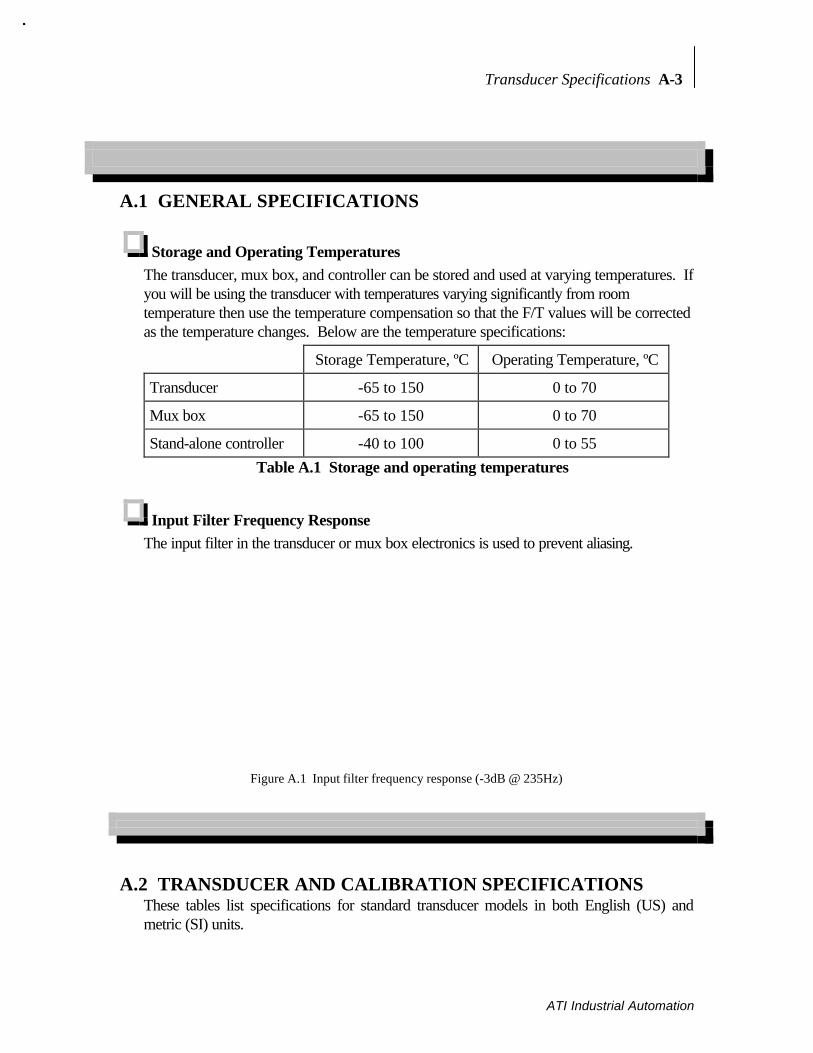
Transducer Specifications A-3
ATI Industrial Automation
A.1 GENERAL SPECIFICATIONS
Storage and Operating TemperaturesThe transducer, mux box, and controller can be stored and used at varying temperatures. Ifyou will be using the transducer with temperatures varying significantly from roomtemperature then use the temperature compensation so that the F/T values will be correctedas the temperature changes. Below are the temperature specifications:
Storage Temperature, ºC Operating Temperature, ºC
Transducer -65 to 150 0 to 70
Mux box -65 to 150 0 to 70
Stand-alone controller -40 to 100 0 to 55Table A.1 Storage and operating temperatures
Input Filter Frequency ResponseThe input filter in the transducer or mux box electronics is used to prevent aliasing.
Figure A.1 Input filter frequency response (-3dB @ 235Hz)
A.2 TRANSDUCER AND CALIBRATION SPECIFICATIONSThese tables list specifications for standard transducer models in both English (US) andmetric (SI) units.

A-4 Transducer Specifications
ATI Industrial Automation
Nano17English (US) Metric (SI)
Calibration US-3-1 US-6-2 US-12-4 SI-12-0.12 SI-25-0.25 SI-50-0.5Rated Sensing Ranges
Fx, Fy ±3 lb ±6 lb ±12 lb ±12.0 N ±25 N ±50 NFz ±4.25 lb ±8.5 lb ±17 lb ±17 N ±35 N ±70 NTx, Ty, Tz ±1 in-lb ±2 in-lb ±4 in-lb ±120 Nmm ±250 Nmm ±500 Nmm
Resolution (minimum)Fx, Fy 1/320 lb 1/160 lb 1/80 lb 1/80 N 1/40 N 1/20 NFz 1/320 lb 1/160 lb 1/80 lb 1/80 N 1/40 N 1/20 NTx, Ty, Tz 1/2000 in-lb 1/1000 in-lb 1/500 in-lb 1/16 Nmm 1/8 Nmm 1/4 Nmm
Counts ValueFx, Fy, Fz 320 / lb 160 / lb 80 / lb 80 / N 40 / N 20 / NTx, Ty, Tz 2000 / in-lb 1000 / in-lb 500 / in-lb 16 / Nmm 8 / Nmm 4 / Nmm
Analog Output Analog Range
Fx, Fy ±3 lb ±6 lb ±12 lb ±12 N ±25 N ±50 N Fz ±3 lb ±6 lb ±12 lb ±12 N ±25 N ±50 N Tx, Ty, Tz ±1 in-lb ±2 in-lb ±4 in-lb ±120 Nmm ±250 Nmm ±500 Nmm
± 5 V Sensitivity Fx, Fy 0.6 lb/V 1.2 lb/V 2.4 lb/V 2.4 N/V 5 N/V 10 N/V Fz 0.6 lb/V 1.2 lb/V 2.4 lb/V 2.4 N/V 5 N/V 10 N/V Tx, Ty, Tz 0.2 in-lb/V 0.4 in-lb/V 0.8 in-lb/V 24 Nmm/V 50 Nmm/V 100 Nmm/V
± 10 V Sensitivity Fx, Fy, Fz 0.3 lb/V 0.6 lb/V 1.2 lb/V 1.2 N/V 2.5 N/V 5 N/V Fz 0.3 lb/V 0.6 lb/V 1.2 lb/V 1.2 N/V 2.5 N/V 5 N/V Tx, Ty, Tz 0.1 in-lb/V 0.2 in-lb/V 0.4 in-lb/V 12 Nmm/V 25 Nmm/V 50 Nmm/V
Tool Transform Factor 0.0016 in/unit 0.0016 in/un 0.0016 in/unit 0.05 mm/unit 0.05 mm/unit 0.05 mm/unit
Physical Properties US MetricStiffness (Calculated)
X-axis and Y-axis force (Kx, Ky) 53×103 lb/in 9.3×10⁶ N/mZ-axis force (Kz) 69×103 lb/in 12×106 N/mX-axis and Y-axis torque (Ktx, Kty) 2.2×10³ in-lb/rad 250 Nm/radZ-axis torque (Ktz) 3.5×10³ in-lb/rad 390 Nm/rad
Resonant Frequency (Measured) Fx, Fy, Tz 7.2 kHz Fz, Tx, Ty 7.2 kHzMaximum Single-axis Load
Fx, Fy ±79 lb ±350 NFz ±180 lb ±820 NTx, Ty ±23 in-lb ±2.6 NmTz ±28 in-lb ±3.1 Nm
WeightTransducer with standard plates 0.021 lb (0.33 oz) 9.4 g
MaterialTransducer Hardened Stainless SteelMounting and tool adapters Aircraft Aluminum

Transducer Specifications A-5
ATI Industrial Automation
Nano25English (US) Metric (SI)
Calibration US-25-25 US-50-50 SI-125-3 SI-250-6Rated Sensing Ranges
Fx, Fy ±25 lb ±50 lb ±125 N ±250 NFz ±100 lb ±200 lb ±500 N ±1000 NTx, Ty ±25 in-lb ±50 in-lb ±3 Nm ±6 NmTz ±25 in-lb ±50 in-lb ±3 Nm ±3.4 Nm
Resolution (minimum)Fx, Fy 1/56 lb 1/28 lb 1/12 N 1/6 NFz 3/56 lb 3/28 lb 1/4 N 1/2 NTx, Ty, 1/40 in-lb 1/20 in-lb 1/330 Nmm 1/165 NmmTz 1/80 in-lb 1/40 in-lb 1/660 Nmm 1/330 Nmm
Counts ValueFx, Fy, Fz 56 / lb 28 / lb 12 / N 6 / NTx, Ty, Tz 80 / in-lb 40 / in-lb 660 / Nm 330 / Nm
Analog Output Analog Range
Fx, Fy ±25 lb ±50 lb ±125 N ±250 N Fz ±25 lb ±50 lb ±125 N ±250 N Tx, Ty, Tz ±25 in-lb ±50 in-lb ±3 Nm ±6 Nm
± 5 V Sensitivity Fx, Fy 5 lb/V 10 lb/V 25 N/V 50 N/V Fz 5 lb/V 10 lb/V 25 N/V 50 N/V Tx, Ty, Tz 5 in-lb/V 10 in-lb/V 0.6 Nm/V 1.2 Nm/V
± 10 V Sensitivity Fx, Fy, Fz 2.5 lb/V 5 lb/V 12.5 N/V 25 N/V Fz 2.5 lb/V 5 lb/V 12.5 N/V 25 N/V Tx, Ty, Tz 2.5 in-lb/V 5 in-lb/V 0.3 Nm/V 0.6 Nm/V
Tool Transform Factor 0.007 in/unit 0.007 in/unit 181.82×10⁻⁶
mm/unit181.82×10-6
mm/unit
Physical Properties US MetricStiffness (Calculated)
X-axis and Y-axis force (Kx, Ky) 300×103 lb/in 53×106 N/mZ-axis force (Kz) 630×103 lb/in 110×106 N/mX-axis and Y-axis torque (Ktx, Kty) 57×103 in-lb/rad 6440 Nm/radZ-axis torque (Ktz) 82×103 in-lb/rad 9260 Nm/rad
Resonant Frequency (Measured) Fx, Fy, Tz 3.6 kHz Fz, Tx, Ty 3.8 kHzMaximum Single-axis Load
Fx, Fy ±520 lb ±2300 NFz ±1400 lb ±6300 NTx, Ty ±310 in-lb ±35 NmTz ±560 in-lb ±63 Nm
WeightTransducer with standard plates 0.14 lb 65 g
MaterialTransducer Hardened Stainless SteelMounting and tool adapters Hardened Stainless Steel

A-6 Transducer Specifications
ATI Industrial Automation
Nano43English (US) Metric (SI)
Calibration US-4-2 US-8-4 SI-18-0.25 SI-36-0.5Rated Sensing Ranges
Fx, Fy ±4 lb ±8 lb ±18 N ±36 NFz ±4 lb ±8 lb ±18 N ±36 NTx, Ty ±2 in-lb ±4 in-lb ±250 Nmm ±500 NmmTz ±2 in-lb ±4 in-lb ±250 Nmm ±500 Nmm
Resolution (minimum)Fx, Fy 1/290 lb 1/145 lb 1/64 N 1/32 NFz 1/290 lb 1/145 lb 1/64 N 1/32 NTx, Ty, 1/580 in-lb 1/64 in-lb 1/5000 Nmm 1/2500 NmmTz 1/580 in-lb 1/64 in-lb 1/5000 Nmm 1/2500 Nmm
Counts ValueFx, Fy, Fz 290 / lb 145 / lb 64 / N 32 / NTx, Ty, Tz 580 / in-lb 290 / in-lb 5 / Nmm 2.5 / Nmm
Analog Output Analog Range
Fx, Fy ±4 lb ±8 lb ±18 N ±36 N Fz ±4 lb ±8 lb ±18 N ±36 N Tx, Ty, Tz ±2 in-lb ±4 in-lb ±250 Nmm ±500 Nmm
± 5 V Sensitivity Fx, Fy 0.8 lb/V 1.6 lb/V 3.6 N/V 7.2 N/V Fz 0.8 lb/V 1.6 lb/V 3.6 N/V 7.2 N/V Tx, Ty, Tz 0.4 in-lb/V 0.8 in-lb/V 50 Nmm/V 100 Nmm/V
± 10 V Sensitivity Fx, Fy, Fz 0.4 lb/V 0.8 lb/V 1.8 N/V 3.6 N/V Fz 0.4 lb/V 0.8 lb/V 1.8 N/V 3.6 N/V Tx, Ty, Tz 0.2 in-lb/V 0.4 in-lb/V 25 Nmm/V 50 Nmm/V
Tool Transform Factor 0.5 in/unit 0.5 in/unit 0.0128 mm/unit 0.0128 mm/unit
Physical Properties US MetricStiffness (Calculated)
X-axis and Y-axis force (Kx, Ky) 30×103 lb/in 5.2×10⁶ N/mZ-axis force (Kz) 30×103 lb/in 5.2×10⁶ N/mX-axis and Y-axis torque (Ktx, Kty) 6.8×10³ in-lb/rad 770 Nm/radZ-axis torque (Ktz) 10×103 in-lb/rad 1.1×10³ Nm/rad
Maximum Single-axis LoadFx, Fy ±68 lb ±300 NFz ±89 lb ±400 NTx, Ty ±30 in-lb ±3.4 NmTz ±48 in-lb ±5.4 Nm
WeightTransducer with standard plates 0.085 lb 39 g
MaterialTransducer Hardened Stainless SteelMounting and tool adapters Aircraft Aluminum
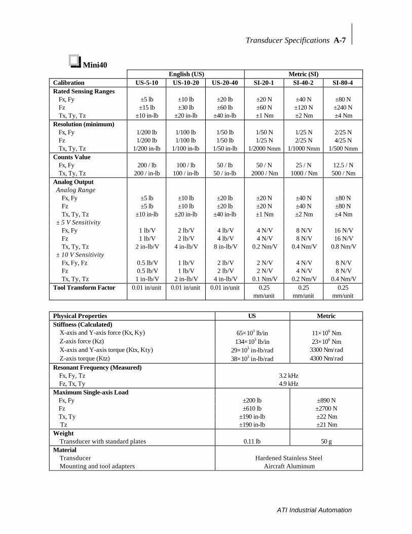
Transducer Specifications A-7
ATI Industrial Automation
Mini40English (US) Metric (SI)
Calibration US-5-10 US-10-20 US-20-40 SI-20-1 SI-40-2 SI-80-4Rated Sensing Ranges
Fx, Fy ±5 lb ±10 lb ±20 lb ±20 N ±40 N ±80 NFz ±15 lb ±30 lb ±60 lb ±60 N ±120 N ±240 NTx, Ty, Tz ±10 in-lb ±20 in-lb ±40 in-lb ±1 Nm ±2 Nm ±4 Nm
Resolution (minimum)Fx, Fy 1/200 lb 1/100 lb 1/50 lb 1/50 N 1/25 N 2/25 NFz 1/200 lb 1/100 lb 1/50 lb 1/25 N 2/25 N 4/25 NTx, Ty, Tz 1/200 in-lb 1/100 in-lb 1/50 in-lb 1/2000 Nmm 1/1000 Nmm 1/500 Nmm
Counts ValueFx, Fy 200 / lb 100 / lb 50 / lb 50 / N 25 / N 12.5 / NTx, Ty, Tz 200 / in-lb 100 / in-lb 50 / in-lb 2000 / Nm 1000 / Nm 500 / Nm
Analog Output Analog Range
Fx, Fy ±5 lb ±10 lb ±20 lb ±20 N ±40 N ±80 N Fz ±5 lb ±10 lb ±20 lb ±20 N ±40 N ±80 N Tx, Ty, Tz ±10 in-lb ±20 in-lb ±40 in-lb ±1 Nm ±2 Nm ±4 Nm
± 5 V Sensitivity Fx, Fy 1 lb/V 2 lb/V 4 lb/V 4 N/V 8 N/V 16 N/V Fz 1 lb/V 2 lb/V 4 lb/V 4 N/V 8 N/V 16 N/V Tx, Ty, Tz 2 in-lb/V 4 in-lb/V 8 in-lb/V 0.2 Nm/V 0.4 Nm/V 0.8 Nm/V
± 10 V Sensitivity Fx, Fy, Fz 0.5 lb/V 1 lb/V 2 lb/V 2 N/V 4 N/V 8 N/V Fz 0.5 lb/V 1 lb/V 2 lb/V 2 N/V 4 N/V 8 N/V Tx, Ty, Tz 1 in-lb/V 2 in-lb/V 4 in-lb/V 0.1 Nm/V 0.2 Nm/V 0.4 Nm/V
Tool Transform Factor 0.01 in/unit 0.01 in/unit 0.01 in/unit 0.25mm/unit
0.25mm/unit
0.25mm/unit
Physical Properties US MetricStiffness (Calculated)
X-axis and Y-axis force (Kx, Ky) 65×103 lb/in 11×106 NmZ-axis force (Kz) 134×103 lb/in 23×106 NmX-axis and Y-axis torque (Ktx, Kty) 29×103 in-lb/rad 3300 Nm/radZ-axis torque (Ktz) 38×103 in-lb/rad 4300 Nm/rad
Resonant Frequency (Measured) Fx, Fy, Tz 3.2 kHz Fz, Tx, Ty 4.9 kHzMaximum Single-axis Load
Fx, Fy ±200 lb ±890 NFz ±610 lb ±2700 NTx, Ty ±190 in-lb ±22 Nm Tz ±190 in-lb ±21 Nm
WeightTransducer with standard plates 0.11 lb 50 g
MaterialTransducer Hardened Stainless SteelMounting and tool adapters Aircraft Aluminum

A-8 Transducer Specifications
ATI Industrial Automation
Mini45English (US) Metric (SI)
Calibration US-30-40 US-60-80 US-120-160
SI-145-5 SI-290-10 SI-580-20
Rated Sensing RangesFx, Fy ±30 lb ±60 lb ±120 lb ±145 N ±290 N ±580 NFz ±60 lb ±120 lb ±240 lb ±290 N ±580 N ±1160 NTx, Ty, Tz ±40 in-lb ±80 in-lb ±160 in-lb ±5 Nm ±10 Nm ±20 Nm
Resolution (minimum)Fx, Fy 1/40 lb 1/20 lb 1/10 lb 1/8 N 1/4 N 1/2 NFz 1/20 lb 1/10 lb 1/5 lb 1/4 N 1/2 N 1 NTx, Ty, Tz 1/44 in-lb 1/22 in-lb 1/11 in-lb 1/376 Nmm 1/188 Nmm 1/94 Nmm
Counts ValueFx, Fy 40 / lb 20 / lb 10 / lb 8 / N 4 / N 2 / NTx, Ty, Tz 44 / in-lb 22 / in-lb 11 / in-lb 376 / Nm 188 / Nm 94 / Nm
Analog Output Analog Range
Fx, Fy ±30 lb ±60 lb ±120 lb ±145 N ±290 N ±580 N Fz ±30 lb ±60 lb ±120 lb ±145 N ±290 N ±580 N Tx, Ty, Tz ±40 in-lb ±80 in-lb ±160 in-lb ±5 Nm ±10 Nm ±20 Nm
± 5 V Sensitivity Fx, Fy 6 lb/V 12 lb/V 24 lb/V 29 N/V 58 N/V 116 N/V Fz 6 lb/V 12 lb/V 24 lb/V 29 N/V 58 N/V 116 N/V Tx, Ty, Tz 8 in-lb/V 16 in-lb/V 32 in-lb/V 1 Nm/V 2 Nm/V 4 Nm/V
± 10 V Sensitivity Fx, Fy, Fz 3 lb/V 6 lb/V 12 lb/V 14.5 N/V 29 N/V 58 N/V Fz 3 lb/V 6 lb/V 12 lb/V 14.5 N/V 29 N/V 58 N/V Tx, Ty, Tz 4 in-lb/V 8 in-lb/V 16 in-lb/V 0.5 Nm/V 1 Nm/V 2 Nm/V
Tool Transform Factor 9.0909 ×10⁻³ in/unit
9.0909 ×10⁻³ in/unit
9.0909 ×10⁻³ in/unit
212.8×10⁻⁶
mm/unit212.8×10-6
mm/unit212.8×10-6
mm/unit
Physical Properties US MetricStiffness (Calculated)
X-axis and Y-axis force (Kx, Ky) 430×103 lb/in 75×106 NmZ-axis force (Kz) 560×103 lb/in 98×106 NmX-axis and Y-axis torque (Ktx, Kty) 150×103 in-lb/rad 17 Nm/radZ-axis torque (Ktz) 310×103 in-lb/rad 35 Nm/rad
Resonant Frequency (Measured) Fx, Fy, Tz 3.2 kHz Fz, Tx, Ty 4.9 kHzMaximum Single-axis Load
Fx, Fy ±1200 lb ±5100 NFz ±2300 lb ±10000 NTx, Ty, Tz ±950 in-lb ±110 NmTx, Ty, Tz ±1200 in-lb ±140 Nm
WeightTransducer with standard plates 0.20 lb 92 g
MaterialTransducer Hardened Stainless SteelMounting and tool adapters Aircraft Aluminum
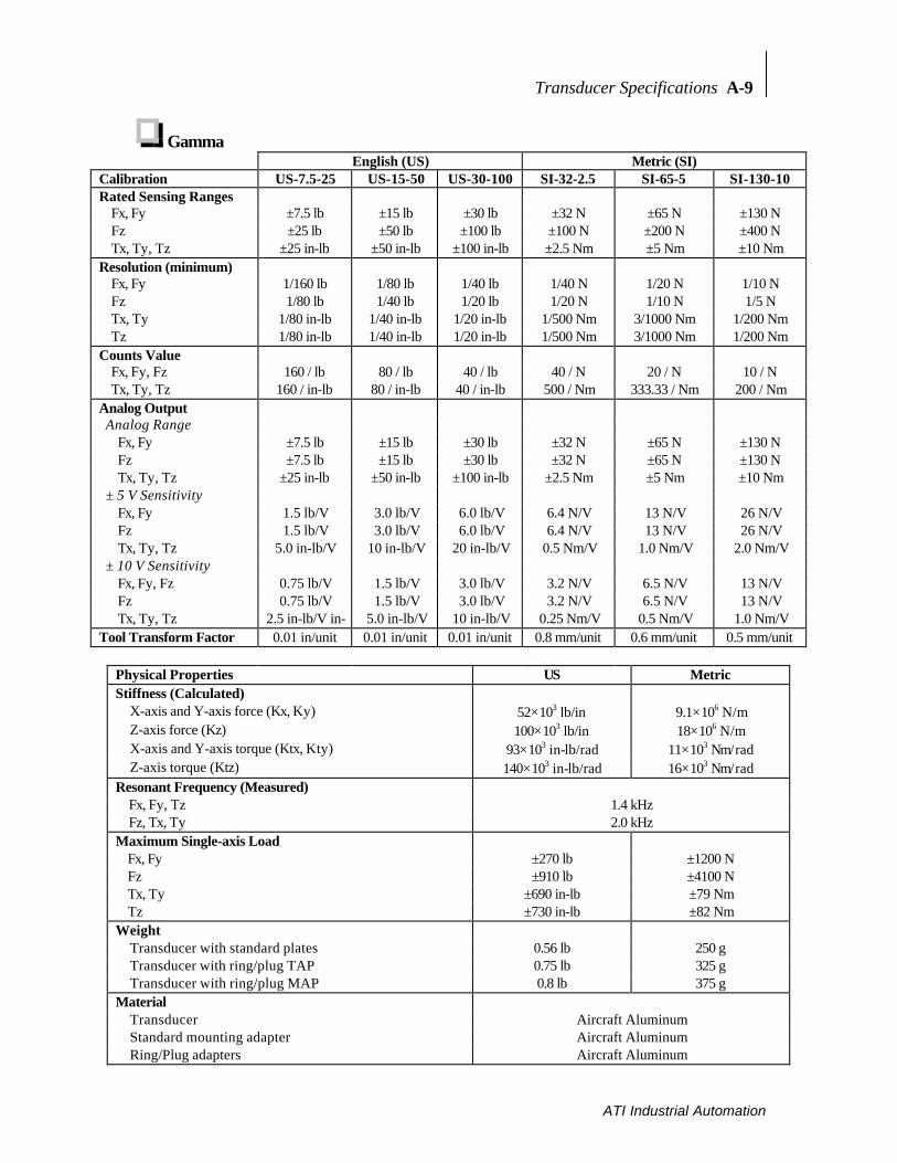
Transducer Specifications A-9
ATI Industrial Automation
GammaEnglish (US) Metric (SI)
Calibration US-7.5-25 US-15-50 US-30-100 SI-32-2.5 SI-65-5 SI-130-10Rated Sensing Ranges
Fx, Fy ±7.5 lb ±15 lb ±30 lb ±32 N ±65 N ±130 NFz ±25 lb ±50 lb ±100 lb ±100 N ±200 N ±400 NTx, Ty, Tz ±25 in-lb ±50 in-lb ±100 in-lb ±2.5 Nm ±5 Nm ±10 Nm
Resolution (minimum)Fx, Fy 1/160 lb 1/80 lb 1/40 lb 1/40 N 1/20 N 1/10 NFz 1/80 lb 1/40 lb 1/20 lb 1/20 N 1/10 N 1/5 NTx, Ty 1/80 in-lb 1/40 in-lb 1/20 in-lb 1/500 Nm 3/1000 Nm 1/200 NmTz 1/80 in-lb 1/40 in-lb 1/20 in-lb 1/500 Nm 3/1000 Nm 1/200 Nm
Counts ValueFx, Fy, Fz 160 / lb 80 / lb 40 / lb 40 / N 20 / N 10 / NTx, Ty, Tz 160 / in-lb 80 / in-lb 40 / in-lb 500 / Nm 333.33 / Nm 200 / Nm
Analog Output Analog Range
Fx, Fy ±7.5 lb ±15 lb ±30 lb ±32 N ±65 N ±130 N Fz ±7.5 lb ±15 lb ±30 lb ±32 N ±65 N ±130 N Tx, Ty, Tz ±25 in-lb ±50 in-lb ±100 in-lb ±2.5 Nm ±5 Nm ±10 Nm
± 5 V Sensitivity Fx, Fy 1.5 lb/V 3.0 lb/V 6.0 lb/V 6.4 N/V 13 N/V 26 N/V Fz 1.5 lb/V 3.0 lb/V 6.0 lb/V 6.4 N/V 13 N/V 26 N/V Tx, Ty, Tz 5.0 in-lb/V 10 in-lb/V 20 in-lb/V 0.5 Nm/V 1.0 Nm/V 2.0 Nm/V
± 10 V Sensitivity Fx, Fy, Fz 0.75 lb/V 1.5 lb/V 3.0 lb/V 3.2 N/V 6.5 N/V 13 N/V Fz 0.75 lb/V 1.5 lb/V 3.0 lb/V 3.2 N/V 6.5 N/V 13 N/V Tx, Ty, Tz 2.5 in-lb/V in- 5.0 in-lb/V 10 in-lb/V 0.25 Nm/V 0.5 Nm/V 1.0 Nm/V
Tool Transform Factor 0.01 in/unit 0.01 in/unit 0.01 in/unit 0.8 mm/unit 0.6 mm/unit 0.5 mm/unit
Physical Properties US MetricStiffness (Calculated)
X-axis and Y-axis force (Kx, Ky) 52×103 lb/in 9.1×10⁶ N/mZ-axis force (Kz) 100×103 lb/in 18×106 N/mX-axis and Y-axis torque (Ktx, Kty) 93×103 in-lb/rad 11×103 Nm/radZ-axis torque (Ktz) 140×103 in-lb/rad 16×103 Nm/rad
Resonant Frequency (Measured) Fx, Fy, Tz 1.4 kHz Fz, Tx, Ty 2.0 kHzMaximum Single-axis Load
Fx, Fy ±270 lb ±1200 NFz ±910 lb ±4100 NTx, Ty ±690 in-lb ±79 NmTz ±730 in-lb ±82 Nm
WeightTransducer with standard plates 0.56 lb 250 gTransducer with ring/plug TAP 0.75 lb 325 gTransducer with ring/plug MAP 0.8 lb 375 g
MaterialTransducer Aircraft AluminumStandard mounting adapter Aircraft AluminumRing/Plug adapters Aircraft Aluminum

A-10 Transducer Specifications
ATI Industrial Automation
DeltaEnglish (US) Metric (SI)
Calibration US-50-150 US-75-300 US-150-600 SI-165-15 SI-330-30 SI-660-60Rated Sensing Ranges
Fx, Fy ±50 lb ±75 lb ±150 lb ±165 N ±330 N ±660 NFz ±150 lb ±225 lb ±450 lb ±495 N ±990 N ±1980 NTx, Ty, Tz ±150 in-lb ±300 in-lb ±600 in-lb ±15 Nm ±30 Nm ±60 Nm
Resolution (minimum)Fx, Fy 1/32 lb 1/16 lb 1/8 lb 1/8 N 1/4 N 1/2 NFz 1/16 lb 1/8 lb 1/4 lb 1/4 N 1/2 N 1 NTx, Ty 3/32 in-lb 3/16 in-lb 3/8 in-lb 1/132 Nm 3/200 Nm 3/100 NmTz 1/16 in-lb 1/8 in-lb 1/4 in-lb 1/132 Nm 3/200 Nm 3/100 Nm
Counts ValueFx, Fy, Fz 32 / lb 16 / lb 8 / lb 8 / N 4 / N 2 / NTx, Ty, Tz 32 / in-lb 16 / in-lb 8 / in-lb 133.3 / Nm 66.7/Nm 33.33/Nm
Analog Output Analog Range
Fx, Fy ±37.5 lb ±75 lb ±150 lb ±165 N ±330 N ±660 N Fz ±37.5 lb ±75 lb ±150 lb ±165 N ±330 N ±660 N Tx, Ty, Tz ±150 in-lb ±300 in-lb ±600 in-lb ±15 Nm ±30 Nm ±60 Nm
± 5 V Sensitivity Fx, Fy 7.5 lb/V 15 lb/V 30 lb/V 33 N/V 66 N/V 132 N/V Fz 7.5 lb/V 15 lb/V 30 lb/V 33 N/V 66 N/V 132 N/V Tx, Ty, Tz 30 in-lb/V 60 in-lb/V 120 in-lb/V 3 Nm 6 Nm/V 12 Nm/V
± 10 V Sensitivity Fx, Fy, Fz 3.75 lb/V 7.5 lb/V 15 lb/V 16.5 N/V 33 N/V 66 N/V Fz 3.75 lb/V 7.5 lb/V 15 lb/V 16.5 N/V 33 N/V 66 N/V Tx, Ty, Tz 15 lb/V 30 in-lb/V 60 in-lb/V 1.5 Nm/V 3 Nm/V 6 Nm/V
Tool Transform Factor 0.01 in/unit 0.01 in/unit 0.01 in/unit 0.6 mm/unit 0.6 mm/unit 0.6 mm/unit
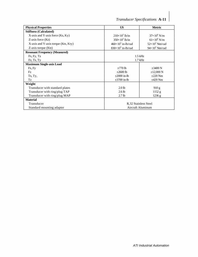
Transducer Specifications A-11
ATI Industrial Automation
Physical Properties US MetricStiffness (Calculated)
X-axis and Y-axis force (Kx, Ky) 210×103 lb/in 37×106 N/mZ-axis force (Kz) 350×103 lb/in 61×106 N/mX-axis and Y-axis torque (Ktx, Kty) 460×103 in-lb/rad 52×103 Nm/radZ-axis torque (Ktz) 830×103 in-lb/rad 94×103 Nm/rad
Resonant Frequency (Measured) Fx, Fy, Tz 1.5 kHz Fz, Tx, Ty 1.7 kHzMaximum Single-axis Load
Fx, Fy ±770 lb ±3400 NFz ±2600 lb ±12,000 NTx, Ty, ±2000 in-lb ±220 NmTz ±3700 in-lb ±420 Nm
WeightTransducer with standard plates 2.0 lb 910 gTransducer with ring/plug TAP 2.6 lb 1152 gTransducer with ring/plug MAP 2.7 lb 1236 g
MaterialTransducer Rc32 Stainless SteelStandard mounting adapter Aircraft Aluminum

A-12 Transducer Specifications
ATI Industrial Automation
ThetaEnglish (US) Metric (SI)
Calibration US-200-1000
US-300-1800
US-600-3600
SI-1000-120
SI-1500-240
SI-2500-400
Rated Sensing RangesFx, Fy ±200 lb ±300 lb ±600 lb ±1000 N ±1500 N ±2500 NFz ±500 lb ±875 lb ±1500 lb ±2500 N ±3750 N ±6250NTx, Ty, Tz ±1000 in-lb ±1800 in-lb ±3600 in-lb ±120 Nm ±240 Nm ±400 Nm
Resolution (minimum)Fx, Fy 1/8 lb 5/17 lb 1/2 lb 1 N 1 N 2 NFz 1/4 lb 10/17 lb 1 lb 1 N 2 N 3 NTx, Ty, Tz 1/2 in-lb 5/4 in-lb 2 in-lb 1/20 Nm 1/10 Nm 1/20 Nm
Counts ValueFx, Fy, Fz 8 / lb 3.4 / lb 2 / lb 2 / N 1 / N 1 / NTx, Ty, Tz 4 / in-lb 0.8 / in-lb 1 / in-lb 20 / Nm 10 / Nm 5 / Nm
Analog Output Analog Range
Fx, Fy ±200 lb ±300 lb ±600 lb ±1000 N ±1500 N ±2500 N Fz ±200 lb ±300 lb ±600 lb ±1000 N ±1500 N ±2500 N Tx, Ty, Tz ±1000 in-lb ±1800 in-lb ±3600 in-lb ±120 Nm ±240 Nm ±400 Nm
± 5 V Sensitivity Fx, Fy 40 lb/V 60 lb/V 120 lb/V 200 N/V 300 N/V 500 N/V Fz 40 lb/V 60 lb/V 120 lb/V 200 N/V 300 N/V 500 N/V Tx, Ty, Tz 200 in-lb/V 360 in-lb/V 720 in-lb/V 24 Nm 48 Nm 80 Nm
± 10 V Sensitivity Fx, Fy, Fz 20 lb/V 30 lb/V 60 lb/V 100 N/V 150 N/V 250 N/V Fz 20 lb/V 30 lb/V 60 lb/V 100 N/V 150 N/V 250 N/V Tx, Ty, Tz 100 lb/V 180 in-lb/V 360 in-lb/V 12 Nm/V 24 Nm/V 40 Nm/V
Tool Transform Factor 0.02 in/unit 0.0425in/unit
0.02 in/unit 1 mm/unit 1 mm/unit 2 mm/unit
Physical Properties US MetricStiffness (Calculated)
X-axis and Y-axis force (Kx, Ky) 420×103 lb/in 73.0×10⁶ N/mZ-axis force (Kz) 710×103 lb/in 125×106 N/mX-axis and Y-axis torque (Ktx, Kty) 3.0×10⁶ in-lb/rad 3.4×10⁵ Nm/radZ-axis torque (Ktz) 4.8×10⁶ in-lb/rad 5.4×10⁵ Nm/rad
Resonant Frequency (Measured) Fx, Fy, Tz 680 Hz Fz, Tx, Ty 820 HzMaximum Single-axis Load
Fx, Fy ±5700 lb ±25,000NFz ±14,000 lb ±61,000 NTx, Ty ±22,000 in-lb ±2500 NmTz ±24,000 in-lb ±2700 Nm
WeightTransducer with standard plates 9.5 lb 4300 g
MaterialTransducer Rc32 Stainless SteelStandard mounting adapter Aircraft Aluminum

Transducer Specifications A-13
ATI Industrial Automation
Omega160English (US) Metric (SI)
Calibration US-200-1000
US-300-1800
US-600-3600
SI-1000-120
SI-1500-240
SI-2500-400
Rated Sensing RangesFx, Fy ±200 lb ±300 lb ±600 lb ±1000 N ±1500 N ±2500 NFz ±500 lb ±875 lb ±1500 lb ±2500 N ±3750 N ±6250NTx, Ty, Tz ±1000 in-lb ±1800 in-lb ±3600 in-lb ±120 Nm ±240 Nm ±400 Nm
Resolution (minimum)Fx, Fy 1/8 lb 5/17 lb 1/2 lb 1 N 1 N 2 NFz 1/4 lb 10/17 lb 1 lb 1 N 2 N 3 NTx, Ty, Tz 1/2 in-lb 5/4 in-lb 2 in-lb 1/20 Nm 1/10 Nm 1/20 Nm
Counts ValueFx, Fy, Fz 8 / lb 3.4 / lb 2 / lb 2 / N 1 / N 1 / NTx, Ty, Tz 4 / in-lb 0.8 / in-lb 1 / in-lb 20 / Nm 10 / Nm 5 / Nm
Analog Output Analog Range
Fx, Fy ±200 lb ±300 lb ±600 lb ±1000 N ±1500 N ±2500 N Fz ±200 lb ±300 lb ±600 lb ±1000 N ±1500 N ±2500 N Tx, Ty, Tz ±1000 in-lb ±1800 in-lb ±3600 in-lb ±120 Nm ±240 Nm ±400 Nm
± 5 V Sensitivity Fx, Fy 40 lb/V 60 lb/V 120 lb/V 200 N/V 300 N/V 500 N/V Fz 40 lb/V 60 lb/V 120 lb/V 200 N/V 300 N/V 500 N/V Tx, Ty, Tz 200 in-lb/V 360 in-lb/V 720 in-lb/V 24 Nm 48 Nm 80 Nm
± 10 V Sensitivity Fx, Fy, Fz 20 lb/V 30 lb/V 60 lb/V 100 N/V 150 N/V 250 N/V Fz 20 lb/V 30 lb/V 60 lb/V 100 N/V 150 N/V 250 N/V Tx, Ty, Tz 100 lb/V 180 in-lb/V 360 in-lb/V 12 Nm/V 24 Nm/V 40 Nm/V
Tool Transform Factor 0.02 in/unit 0.0425in/unit
0.02 in/unit 1 mm/unit 1 mm/unit 2 mm/unit
Physical Properties US MetricStiffness (Calculated)
X-axis and Y-axis force (Kx, Ky) 400×103 lb/in 70.0×10⁶ N/mZ-axis force (Kz) 680×103 lb/in 120×106 N/mX-axis and Y-axis torque (Ktx, Kty) 2.9×10⁶ in-lb/rad 3.3×10⁵ Nm/radZ-axis torque (Ktz) 4.7×10⁶ in-lb/rad 5.3×10⁵ Nm/rad
Resonant Frequency (Measured) Fx, Fy, Tz 1.3 kHz Fz, Tx, Ty 1.0 kHzMaximum Single-axis Load
Fx, Fy ±4000 lb ±18,000NFz ±11,000 lb ±48,000 NTx, Ty, Tz ±15,000 lb ±1700 NmTx, Ty, Tz ±17,000 lb ±1900 Nm
WeightTransducer with standard plates 6.0 lb 2700 g
MaterialTransducer Hardened Stainless SteelMounting and tool adapters Aircraft Aluminum
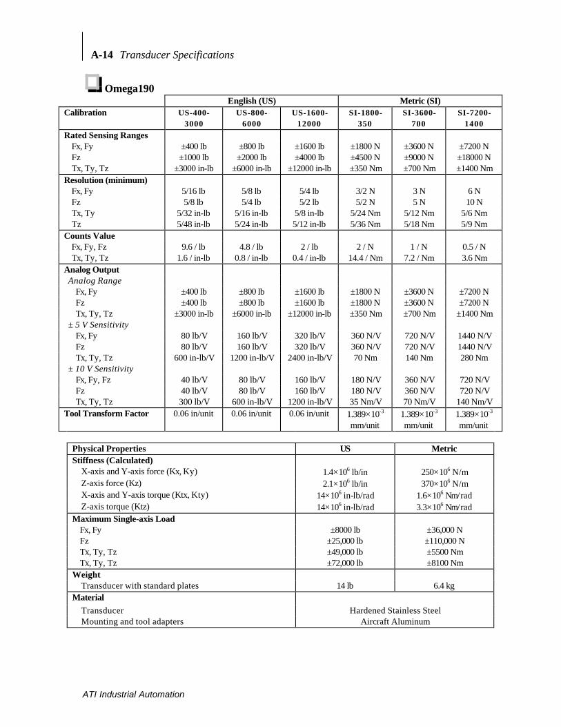
A-14 Transducer Specifications
ATI Industrial Automation
Omega190English (US) Metric (SI)
Calibration US-400-3000
US-800-6000
US-1600-12000
SI-1800-350
SI-3600-700
SI-7200-1400
Rated Sensing RangesFx, Fy ±400 lb ±800 lb ±1600 lb ±1800 N ±3600 N ±7200 NFz ±1000 lb ±2000 lb ±4000 lb ±4500 N ±9000 N ±18000 NTx, Ty, Tz ±3000 in-lb ±6000 in-lb ±12000 in-lb ±350 Nm ±700 Nm ±1400 Nm
Resolution (minimum)Fx, Fy 5/16 lb 5/8 lb 5/4 lb 3/2 N 3 N 6 NFz 5/8 lb 5/4 lb 5/2 lb 5/2 N 5 N 10 NTx, Ty 5/32 in-lb 5/16 in-lb 5/8 in-lb 5/24 Nm 5/12 Nm 5/6 NmTz 5/48 in-lb 5/24 in-lb 5/12 in-lb 5/36 Nm 5/18 Nm 5/9 Nm
Counts ValueFx, Fy, Fz 9.6 / lb 4.8 / lb 2 / lb 2 / N 1 / N 0.5 / NTx, Ty, Tz 1.6 / in-lb 0.8 / in-lb 0.4 / in-lb 14.4 / Nm 7.2 / Nm 3.6 Nm
Analog Output Analog Range
Fx, Fy ±400 lb ±800 lb ±1600 lb ±1800 N ±3600 N ±7200 N Fz ±400 lb ±800 lb ±1600 lb ±1800 N ±3600 N ±7200 N Tx, Ty, Tz ±3000 in-lb ±6000 in-lb ±12000 in-lb ±350 Nm ±700 Nm ±1400 Nm
± 5 V Sensitivity Fx, Fy 80 lb/V 160 lb/V 320 lb/V 360 N/V 720 N/V 1440 N/V Fz 80 lb/V 160 lb/V 320 lb/V 360 N/V 720 N/V 1440 N/V Tx, Ty, Tz 600 in-lb/V 1200 in-lb/V 2400 in-lb/V 70 Nm 140 Nm 280 Nm
± 10 V Sensitivity Fx, Fy, Fz 40 lb/V 80 lb/V 160 lb/V 180 N/V 360 N/V 720 N/V Fz 40 lb/V 80 lb/V 160 lb/V 180 N/V 360 N/V 720 N/V Tx, Ty, Tz 300 lb/V 600 in-lb/V 1200 in-lb/V 35 Nm/V 70 Nm/V 140 Nm/V
Tool Transform Factor 0.06 in/unit 0.06 in/unit 0.06 in/unit 1.389×10⁻³
mm/unit1.389×10-3
mm/unit1.389×10-3
mm/unit
Physical Properties US MetricStiffness (Calculated)
X-axis and Y-axis force (Kx, Ky) 1.4×10⁶ lb/in 250×106 N/mZ-axis force (Kz) 2.1×10⁶ lb/in 370×106 N/mX-axis and Y-axis torque (Ktx, Kty) 14×106 in-lb/rad 1.6×10⁶ Nm/radZ-axis torque (Ktz) 14×106 in-lb/rad 3.3×10⁶ Nm/rad
Maximum Single-axis LoadFx, Fy ±8000 lb ±36,000 NFz ±25,000 lb ±110,000 NTx, Ty, Tz ±49,000 lb ±5500 NmTx, Ty, Tz ±72,000 lb ±8100 Nm
WeightTransducer with standard plates 14 lb 6.4 kg
MaterialTransducer Hardened Stainless SteelMounting and tool adapters Aircraft Aluminum

Transducer Specifications A-15
ATI Industrial Automation
A.3 COMPOUND LOADING RANGES OF F/T SENSORS
The F/T sensor’s strain gages are optimally placed to share information between the forces andtorques applied to the sensor. Because of this sharing, it is possible to saturate the transducerwith a complex load that has components below the rated load of the sensor. However, thisarrangement allows a greater sensing range and resolution.
These graphs may be used to estimate a sensor’s range under complex loading. Each pagerepresents one sensor body, with either English or Metric units. The top graph representscombinations of forces in the x and/or y directions with torques about the z-axis. The bottomgraph represents combinations of z-axis forces with x- and/or y-axis torques. The graphscontain several different calibrations, distinguished by line weight.
The following sample graph shows how operating ranges can change with complex loading.The labels indicate the following regions:
A. Normal operating region. You can expect to achieve rated accuracy in this region.B. Saturation region. Any load in this region will report a gage saturation condition.C. Extended operating region. In this region, the sensor will operate correctly, but the full-scale accuracy is not guaranteed.

A-16 Transducer Specifications
ATI Industrial Automation
Nano17 (US Calibration)
15202520253035
: Nano17 US-12-4 : Nano17 US-6-2 : Nano17 US-3-1

Transducer Specifications A-17
ATI Industrial Automation
Nano17 (SI Calibration)
80100120140100120140160180
: Nano17 SI-50-0.5 : Nano17 SI-25-0.25 : Nano17 SI-12-0.12

A-18 Transducer Specifications
ATI Industrial Automation
Nano25 (US Calibration)
405060708090200250300350
: Nano25 US-50-50 : Nano25 US-25-25

Transducer Specifications A-19
ATI Industrial Automation
Nano25 (SI Calibration)
2002503003504008001000120014001600
: Nano25 SI-250-6 : Nano25 SI-125-3

A-20 Transducer Specifications
ATI Industrial Automation
Nano43 (US Calibration)
81012141618810121416
: Nano43 US-8-4 : Nano43 US-4-2

Transducer Specifications A-21
ATI Industrial Automation
Nano43 (SI Calibration)
405060708040506070
: Nano43 SI-36-0.5 : Nano43 SI-18-0.25

A-22 Transducer Specifications
ATI Industrial Automation
Mini40 (US Calibration)
25303540455080100120140160
: Mini40 US-20-40 : Mini40 US-10-20 : Mini40 US-5-10

Transducer Specifications A-23
ATI Industrial Automation
Mini40 (SI Calibration)
100120140160180200300400500600
: Mini40 SI-80-4 : Mini40 SI-40-2 : Mini40 SI-20-1

A-24 Transducer Specifications
ATI Industrial Automation
Mini45 (US Calibration)
150200250300400500600700
: Mini45 US-120-160 : Mini45 US-60-80 : Mini45 US-30-40

Transducer Specifications A-25
ATI Industrial Automation
Mini45 (SI Calibration)
800100012001400160020002500300035004000
: Mini45 SI-580-20 : Mini45 SI-290-10 : Mini45 SI-145-5

A-26 Transducer Specifications
ATI Industrial Automation
Gamma (US Calibration)
30405060100120140160180200
: Gamma US-30-100 : Gamma US-15-50 : Gamma US-7.5-25

Transducer Specifications A-27
ATI Industrial Automation
Gamma (SI Calibration)
150200250400500600700800
: Gamma SI-130-10 : Gamma SI-65-5 : Gamma SI-32-2.5

A-28 Transducer Specifications
ATI Industrial Automation
Delta (US Calibration)
1502002503005006007008009001000
: Delta US-150-600 : Delta US-75-300 : Delta US-50-150

Transducer Specifications A-29
ATI Industrial Automation
Delta (SI Calibration)
6008001000120020002500300035004000
: Delta SI-660-60 : Delta SI-330-30 : Delta SI-165-15

A-30 Transducer Specifications
ATI Industrial Automation
Theta (US Calibration)
600800100012001500200025003000
: Theta US-600-3600 : Theta US-300-1800 : ThetaUS-200-1000

Transducer Specifications A-31
ATI Industrial Automation
Theta (SI Calibration)
2500300035004000450050008000100001200014000
: Theta SI-2500-400 : Theta SI-1500-240 : Theta SI-1000-120

A-32 Transducer Specifications
ATI Industrial Automation
Omega160 (US Calibration)
600800100012001500200025003000
: Omega160 US-600-3600 : Omega160 US-300-1800 : Omega160 US- 200-1000

Transducer Specifications A-33
ATI Industrial Automation
Omega160 (SI Calibration)
2000250030003500400045008000100001200014000
: Omega160 SI-2500-400 : Omega160 SI-1500-240 : Omega160 SI-1000-120

A-34 Transducer Specifications
ATI Industrial Automation
Omega190 (US Calibration)
15002000250030005000600070008000900010000

Transducer Specifications A-35
ATI Industrial Automation
: Omega190 US-1600-12000 : Omega190 US-800-6000 : Omega190 US- 400-3000
Omega190 (SI Calibration)
600080001000012000200002500030000350004000045000
: Omega190 SI-7200-1400 : Omega190 SI-3600-700 : Omega190 SI-1800-350

B
Mechanical Layout
Nano17 Transducer with Tool and Mounting Adapter Plate ........................................B-2 Nano25 Transducer with Tool and Mounting Adapter Plate ........................................B-3 Nano43 Transducer with Tool and Mounting Adapter Plate ........................................B-4 Mini40 Transducer with Tool and Mounting Adapter Plate .........................................B-5 Mini45 Transducer with Tool and Mounting Adapter Plate .........................................B-6 Gamma Transducer with Tool and Mounting Adapter Plate ........................................B-7 Delta Transducer with Tool and Mounting Adapter Plate ............................................B-8 Theta Transducer with Tool and Mounting Adapter Plate ...........................................B-9 Omega 160 Transducer with Tool and Mounting Adapter Plate ..................................B-10 Omega 190 Transducer with Tool and Mounting Adapter Plate ..................................B-11 Gamma Mounting Adapter Plate ..................................................................................B-12 Delta Mounting Adapter Plate .......................................................................................B-13 Theta Mounting Adapter Plate.......................................................................................B-14 Gamma and Delta Mounting Ring-plug Adapter..........................................................B-15 Gamma and Delta Tool Ring-plug Adapter...................................................................B-16 F/T Controller Chassis ....................................................................................................B-17 Mux Box Chassis ............................................................................................................B-18

B-2 Mechanical Layout
ATI Industrial Automation

B-3 Mechanical Layout
ATI Industrial Automation

B-4 Mechanical Layout
ATI Industrial Automation

B-5 Mechanical Layout
ATI Industrial Automation

B-6 Mechanical Layout
ATI Industrial Automation

B-7 Mechanical Layout
ATI Industrial Automation

B-8 Mechanical Layout
ATI Industrial Automation
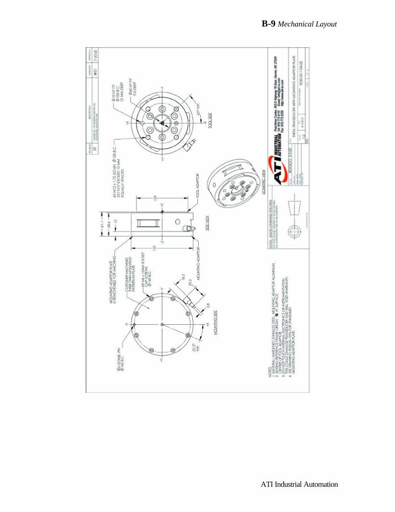
B-9 Mechanical Layout
ATI Industrial Automation

B-10 Mechanical Layout
ATI Industrial Automation

B-11 Mechanical Layout
ATI Industrial Automation
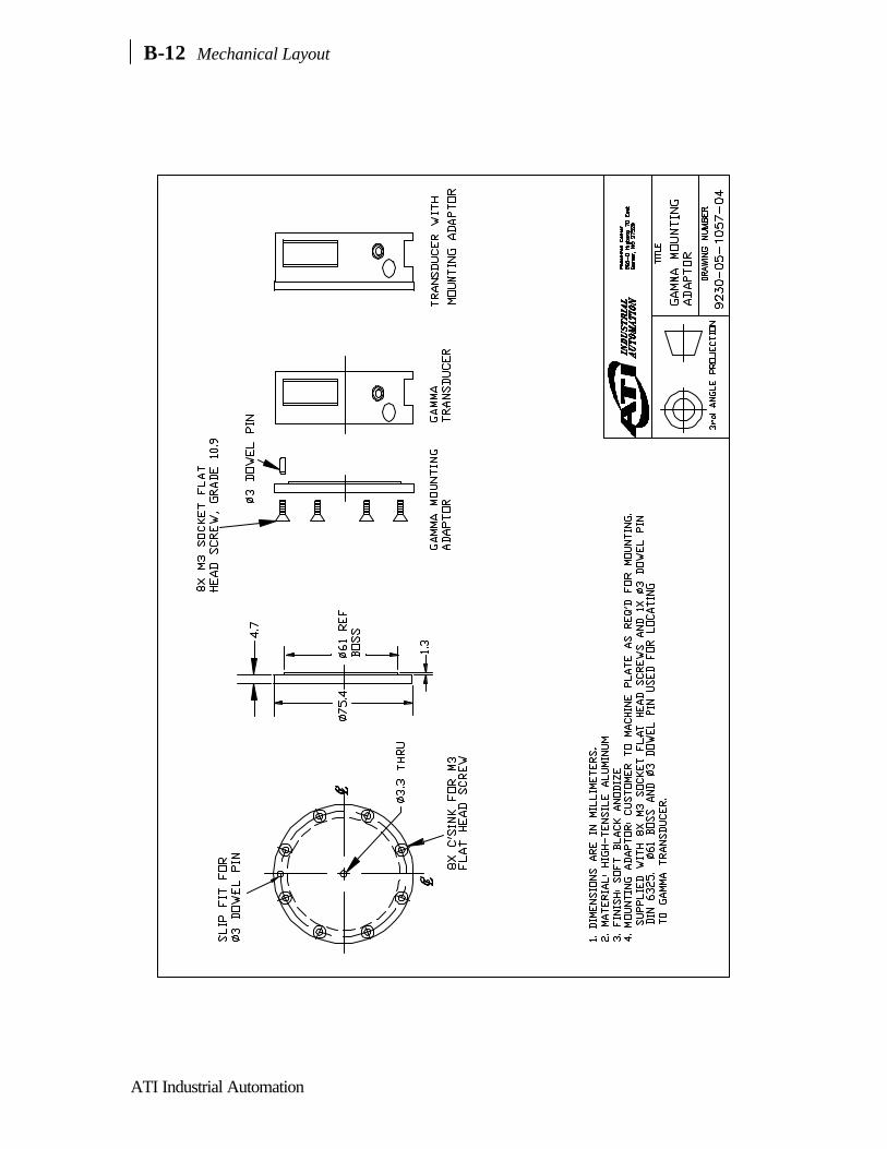
B-12 Mechanical Layout
ATI Industrial Automation

B-13 Mechanical Layout
ATI Industrial Automation

B-14 Mechanical Layout
ATI Industrial Automation
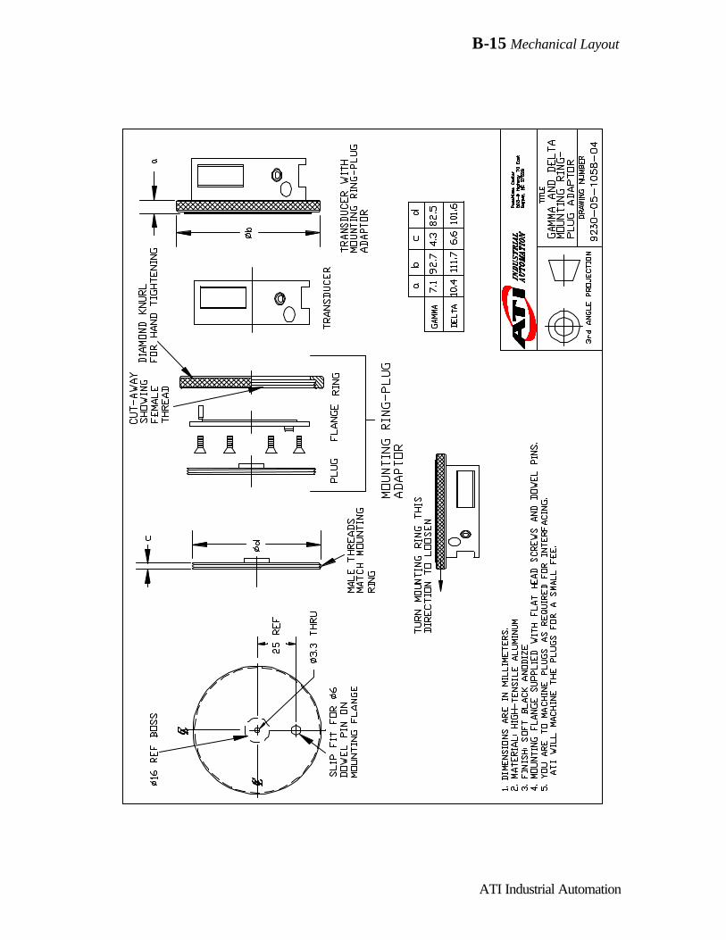
B-15 Mechanical Layout
ATI Industrial Automation

B-16 Mechanical Layout
ATI Industrial Automation

B-17 Mechanical Layout
ATI Industrial Automation
Stand –alone Controller Chassis: Dimensions in Millimeters

B-18 Mechanical Layout
ATI Industrial Automation

CCalibrationMatrix andAdditional
Information

DDual Gain
Calibration
Instructions
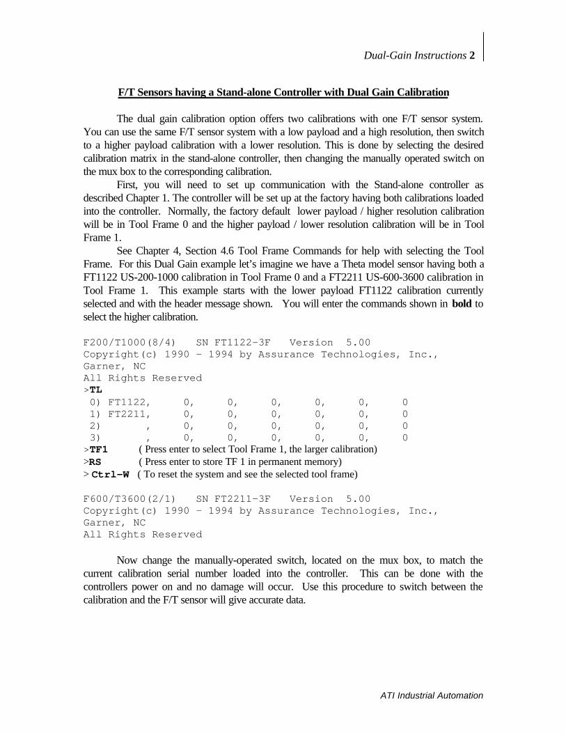
Dual-Gain Instructions 2
ATI Industrial Automation
F/T Sensors having a Stand-alone Controller with Dual Gain Calibration
The dual gain calibration option offers two calibrations with one F/T sensor system.You can use the same F/T sensor system with a low payload and a high resolution, then switchto a higher payload calibration with a lower resolution. This is done by selecting the desiredcalibration matrix in the stand-alone controller, then changing the manually operated switch onthe mux box to the corresponding calibration.
First, you will need to set up communication with the Stand-alone controller asdescribed Chapter 1. The controller will be set up at the factory having both calibrations loadedinto the controller. Normally, the factory default lower payload / higher resolution calibrationwill be in Tool Frame 0 and the higher payload / lower resolution calibration will be in ToolFrame 1.
See Chapter 4, Section 4.6 Tool Frame Commands for help with selecting the ToolFrame. For this Dual Gain example let’s imagine we have a Theta model sensor having both aFT1122 US-200-1000 calibration in Tool Frame 0 and a FT2211 US-600-3600 calibration inTool Frame 1. This example starts with the lower payload FT1122 calibration currentlyselected and with the header message shown. You will enter the commands shown in bold toselect the higher calibration.
F200/T1000(8/4) SN FT1122-3F Version 5.00Copyright(c) 1990 - 1994 by Assurance Technologies, Inc.,Garner, NCAll Rights Reserved>TL 0) FT1122, 0, 0, 0, 0, 0, 0 1) FT2211, 0, 0, 0, 0, 0, 0 2) , 0, 0, 0, 0, 0, 0 3) , 0, 0, 0, 0, 0, 0>TF1 ( Press enter to select Tool Frame 1, the larger calibration)>RS ( Press enter to store TF 1 in permanent memory)> Ctrl-W ( To reset the system and see the selected tool frame)
F600/T3600(2/1) SN FT2211-3F Version 5.00Copyright(c) 1990 - 1994 by Assurance Technologies, Inc.,Garner, NCAll Rights Reserved
Now change the manually-operated switch, located on the mux box, to match thecurrent calibration serial number loaded into the controller. This can be done with thecontrollers power on and no damage will occur. Use this procedure to switch between thecalibration and the F/T sensor will give accurate data.

Dual-Gain Instructions 3
ATI Industrial Automation
! Warning... If the serial numbers do not match, the Force andTorque data will be incorrect.