Embed Size (px)
Citation preview

INSTALLATIONAND
OPERATION MANUAL
R 5 SeriesModels 0025, 0040, 0063, 0100, 0101 and 0250 C/E
Single Stage Rotary Vane Vacuum Pumps


Page
GENERAL 2
Identification 2Operating Principles 2
1.0 INSTALLATION 21.1 Unpacking 21.2 Location 21.3 Power Requirements 21.4 Vacuum Connections and Drip Legs 31.5 Oil Filling 3
2.0 OPERATION 42.1 Start-up 42.2 Gas Ballast 42.3 Process Gas 52.4 Stopping Pump 52.5 Water-Cooled Pumps (optional) 52.6 Oxygen Service Pumps 5
3.0 ROUTINE MAINTENANCE 63.1 Pump Oil 63.1.1 Oil Filter 63.1.2 Oil Type and Quantity 63.1.3 Oil and Filter Change 63.1.4 Oil Flushing procedure 73.2 Automotive-Type Oil Filter 83.3 Exhaust Filter 83.4 Inlet Flange 93.5 Vacuum Inlet Filter (optional) 93.6 Routine Maintenance Schedule 93.7 Overhaul Kit/Filter 9
4.0 TROUBLESHOOTING 9
5.0 LIMITED STANDARD WARRANTY 14
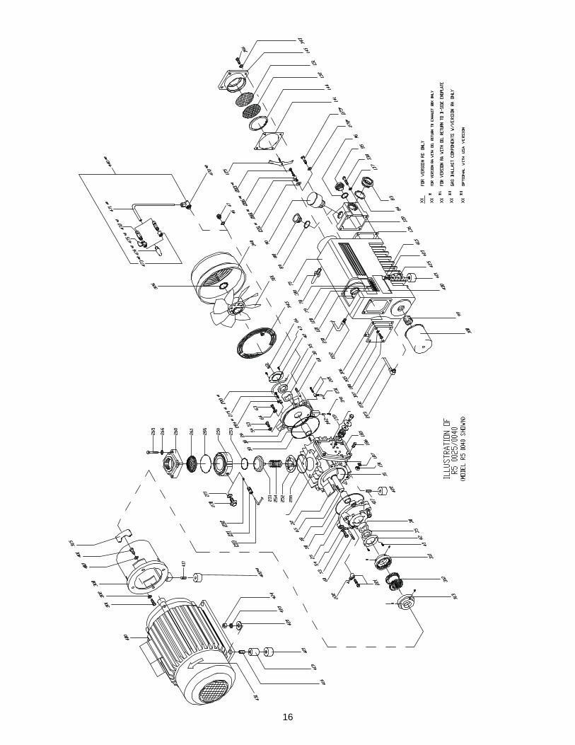
Technical Data 14Parts List 15Illustration of R 5 0025-0040 16Illustration of R 5 0063-0101 17Illustration of R 5 0250 18Busch Factory Service Centers 19
We reserve the right to change the product at any time without any form of notification. The information in this pub-lication is accurate to the best of our ability at the time of printing. Busch, Inc. will not be responsible for errorsencountered when attempting to perform tasks outlined in this publication which is copyright protected.
TABLE OF CONTENTS
1

GENERAL
Identification
For model identification, see the nameplate mounted onthe side of the exhaust box.
This manual is written to cover RA and RC versions ofmodels 0025, 0040, 0063, 0100, 0101 and 0250 with a"C" or "E" appearing as the seventh character in themodel type number stamped into the nameplate. Forexample, it would appear as follows:
RAXXXX-CXXX-XXXX
When ordering parts, it is helpful to include the identifi-cation code stamped into the side of the cylinder as wellas the serial number from the nameplate.
Operating Principles
All reference (Ref. XXX) numbers listed in the text andon illustrations throughout this manual are related to thedrawings and parts list shown later in this publication.
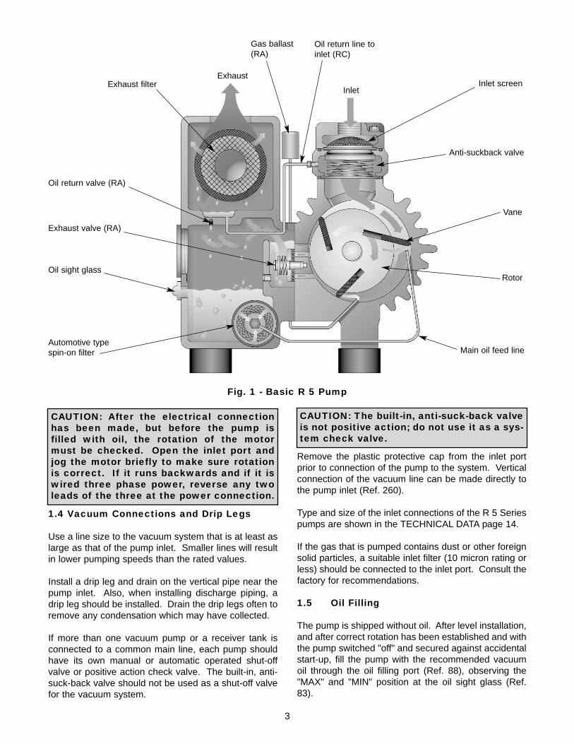
All R 5 Series, Single Stage, Rotary Vacuum Pumps aredirect-driven, air-cooled, oil-sealed, rotary vane pumpsthat operate as positive displacement pumps. Theyconsist of a rotor positioned eccentrically in a cylindricalstator (see Fig. 1). The rotor has three radially slidingvanes which divide the pump chamber into three seg-ments. When the rotor spins, centrifugal force pushesthe vanes, which glide in the slots, towards the wall ofthe cylinder. The rotor has three vanes which divide thepump chamber into three segments. The gas to bepumped enters at the inlet port, passes through the inletscreen and the open anti-suck-back valve into thepump chamber. As the rotor rotates, the inlet apertureis closed, the gas is compressed and forced out throughone-way valves between the pump cylinder and theexhaust box. This operation is repeated three timeseach revolution.
1.0 INSTALLATION
1.1 Unpacking
Inspect the box and pump carefully for any signs ofdamage incurred in transit. Since all pumps are ordi-narily shipped FOB our factory, such damage is the nor-
2
mal responsibility of the carrier and should be reportedto them.
Remove the nuts from the bottom of the box/crate andpull the pump out of the container, then unscrew thestuds from the bottom of the rubber feet.
The inlet port of the pump is covered with a plastic capprior to shipment to prevent dirt and other foreign mate-rial from entering the pump. Do not remove this coveruntil the pump is actually ready for connection to yoursystem.
1.2 Location
The pump must be installed in a horizontal position ona level surface so that the pump is evenly supported onits rubber feet. Allow sufficient air space between thepump and any walls or other obstructions; adequateventilation must be provided for the fans on the pumpand motor (i.e., do not locate the pump in a stagnant airlocation).
Whenever the pump is transported, be sure to drain theoil prior to shipping to avoid vane breakage whenrestarting the pump.
Do not tip the pump over if it is filled with oil.
Locate the pump for easy access to the oil sight glass(Ref. 83) in order to inspect and control the oil levelproperly. Allow clearance at the exhaust flange area toprovide service access to the exhaust filters.
1.3 Power Requirements
The schematic diagram for the electrical connection islocated in the junction box or on the nameplate of thepump motor.
The motor must be connected according to the electri-cal codes governing the installation. The power supplymust be routed through a fused switch to protect themotor against electrical or mechanical overloads. Themotor starter has to be set consistent with the motorcurrent listed on the motor nameplate.
If the pump is supplied with a manual motor starter, it ispreset at the factory in accordance with the customer’sspecification. For other voltage requirements, contactthe factory for motor and/or starter information.
Note: See the motor manufacturer’s manual for start-up maintenance of the motor.
Correct direction of rotation is marked by an arrow onthe motor fan housing and is counterclockwise whenlooking at the motor from the motor's fan side.
All R 5 series pumps are designed to handle air.Vapor in the air stream can be tolerated when thepump is operated within certain operating parametersas defined by Busch, Inc. Engineering (see Section2.2 - Gas Ballast). When you desire to use the pumpon an air stream that contains vapors, contact Busch,Inc. Engineering for operating recommendations; oth-erwise, the warranty could be void.
3
1.4 Vacuum Connections and Drip Legs
Use a line size to the vacuum system that is at least aslarge as that of the pump inlet. Smaller lines will resultin lower pumping speeds than the rated values.
Install a drip leg and drain on the vertical pipe near thepump inlet. Also, when installing discharge piping, adrip leg should be installed. Drain the drip legs often toremove any condensation which may have collected.
If more than one vacuum pump or a receiver tank isconnected to a common main line, each pump shouldhave its own manual or automatic operated shut-offvalve or positive action check valve. The built-in, anti-suck-back valve should not be used as a shut-off valvefor the vacuum system.
Remove the plastic protective cap from the inlet portprior to connection of the pump to the system. Verticalconnection of the vacuum line can be made directly tothe pump inlet (Ref. 260).
Type and size of the inlet connections of the R 5 Seriespumps are shown in the TECHNICAL DATA page 14.
If the gas that is pumped contains dust or other foreignsolid particles, a suitable inlet filter (10 micron rating orless) should be connected to the inlet port. Consult thefactory for recommendations.
1.5 Oil Filling
The pump is shipped without oil. After level installation,and after correct rotation has been established and withthe pump switched "off" and secured against accidentalstart-up, fill the pump with the recommended vacuumoil through the oil filling port (Ref. 88), observing the"MAX" and "MIN" position at the oil sight glass (Ref.83).
CAUTION: The built-in, anti-suck-back valveis not positive action; do not use it as a sys-tem check valve.
Exhaust
InletExhaust filter
Gas ballast(RA)
Rotor
Anti-suckback valve
Inlet screen
Vane
Automotive typespin-on filter Main oil feed line
Exhaust valve (RA)
Oil return valve (RA)
Oil sight glass
Oil return line toinlet (RC)
Fig. 1 - Basic R 5 Pump
CAUTION: After the electrical connectionhas been made, but before the pump isfilled with oil, the rotation of the motormust be checked. Open the inlet port andjog the motor briefly to make sure rotationis correct. If it runs backwards and if it iswired three phase power, reverse any twoleads of the three at the power connection.

4
Non-detergent oil should be used. Do not usedetergent motor oil as additives in detergent oil willplug exhaust filter elements and shorten their life.
It is recommended that Busch R500 Series oil be usedto receive the best performance from your vacuumequipment. R500 Series oil is a high quality vacuum oilthat will give longer running time between oil changes,will provide better lubrication at high operating temper-atures, and will prolong the life of exhaust filter ele-ments. This oil can be obtained directly from Busch,Inc. in Virginia Beach, Virginia.
The strict use of Busch oils and parts from the day ofpurchase can extend the Limited Standard Warranty tothree years. Contact Busch, Inc. in Virginia Beach,Virginia for details.
For general applications, use R530 in all models cov-ered by this manual. Use R590 or R570 in pumps thatare operated in high ambient temperatures (above90°F) or when the oil carbonizes (turns black) beforethe change interval. Use R590 or R570 on 0250pumps. Contact the factory for recommendations whenusing other oils.
The TECHNICAL DATA chart on page 14 gives theapproximate quantities of oil required for each pump.The oil capacity chart should only be used as a guide,since oil capacity may be slightly lower, depending onwhether the pump was filled previously, and whether allcomponents such as oil filter, oil lines, etc., wereallowed to completely drain. Use only the sight glassreading for proper level. Never overfill!
For ambient operating temperatures lower than 41°F,use Busch R580 synthetic oil. If this does not help(where the pump has difficulty starting due to high oilviscosity), contact the factory in Virginia Beach,Virginia.
Replace the oil fill plug (Ref. 88), making sure that thegasket (Ref. 89) is in place and properly seated andsecured. Some pumps are equipped with an exhaustpressure gauge as an integral part of the oil fill plug.Switch the power back into the "on" position.
2.0 OPERATION
2.1 Start-up
Check rotation of the motor as described in Section 1.3
- Power Requirements.
Fill the pump with oil as described in Section 1.5 - OilFilling.
Start the pump and immediately close the inlet. Run thepump for a few minutes before checking the oil levelagain. With the pump shut off, the oil level should bevisible in the oil sight glass (Ref. 83), between the "MIN"and "MAX" mark.
Add oil, if necessary, but only add it when the pump hasbeen shut off and the circulating oil has had sufficienttime to return to the oil sump.
Note: The oil separated by the exhaust filter elementforms droplets on the outside of the exhaust filter thatcollect at a low point in the upper half of the exhaustbox. From there the collected oil is drained back to theoil sump via an oil check valve (Ref. 275) which openson R 5 RA model pumps when the pump is shut off. Itis necessary to shut off the RA model pumps after every8 hours of operation to allow the check valve to open.If the pump is not shut off after this time period, it is pos-sible to starve the pump of oil since the oil is not allowedto drain back into the oil sump and/or oil droplets maybe blown out of the exhaust. If the pump is operating athigh pressure it may be necessary to shut it down soon-er than 8 hours.
On R 5 (Standard) RC model pumps, the collected oil isdrawn continuously during operation of the vacuumpump to the inlet flange (Ref. 260) via the oil return line(Ref. 290). The oil return line is connected directly tothe area of the exhaust box, downstream of the exhaustfilter, which is at atmospheric pressure. Therefore, aconstant amount of air is sucked into the pump, whichis an additional reason that the R 5 Standard SeriesPumps do not achieve as low a vacuum as the R 5Series Super Vacuum Pumps. RC model pumps canrun continuously without having to shut them off for theoil to drain back.
2.2 Gas Ballast
All RA Series pumps are equipped with a gas ballastvalve. The gas ballast valve (Ref. 440) is locatedbetween the inlet port and the exhaust box. RA seriespumps are equipped with a permanent gas ballastwhich cannot be shut off unless the sintered filter isremoved and the orifice plugged. Larger pumps areequipped with an adjustable gas ballast valve.
The adjustable gas ballast valve should normally be leftopen. Its primary function is to prevent water vaporfrom condensing in the pump. Condensation causesemulsification of the oil, loss of lubricity, and possiblerotor seizure.
WARNING: Keep the oil fill plug tight aspressure in the exhaust box could causebodily injury if the plug is blown out. Do notfill/add the pump with oil through theexhaust/inlet ports as there is danger ofbreaking the vanes!

5
2.3 Process Gas
The R 5 series pumps are designed to pump air and arenot intended for use when water vapor is beingpumped. In some applications, when the quantity of thewater vapor is moderate, R 5 pumps have been usedwith good results. On these occasions, the pump is rununtil it is up to operating temperature before it is allowedto pump the process gas. The pump is also operatedfor a period of time off process and on air (to clear it ofprocess gas) before it is shut down. This operatingtechnique prevents the vapor from condensing in thepump. Before attempting to pump a gas laden withwater vapor, contact Busch Engineering for advice.
2.4 Stopping Pump
To stop the pump, turn off the power. The pump has abuilt-in, anti-suck-back valve (Ref. 251 thru 255) to pre-vent the pump from rotating backwards when it is shutoff.
Install an automatic operated valve (such as a checkvalve) in front of the pump, if more than one pump ispumping on the same line or if there is a sufficient vol-ume of vacuum in the system to cause the pump oil tobe drawn into the piping when that pump is shut down.
All R 5 Series pumps are vented internally to atmos-pheric pressure through venting holes that are next tothe exhaust valve assembly.
2.5 Water-Cooled Pumps (optional)
Water-cooled pumps are cooled by circulating the oilthrough a shell-and-tube type heat exchanger. The cir-culation of the pump oil through the shell is created byvacuum in the pump, but the circulation of the coolingwater through the tubes is thermostatically controlled.The flow rate of the cooling water is controlled by a ther-mostatically activated valve (see Fig. 2) that senses,through a capillary bulb mounted in the exhaust box,the pump's oil temperature as it is discharged from thecompression chamber. The valve will open at its setpoint and close at approximately 3°F to 5°F below theset point. The valve set point is adjustable as follows:
(a) Rotate the valve adjustment screw counterclock-wise to cause the valve to open at a higher tempera-ture. This makes the pump run hotter.
(b) Rotate the valve adjustment screw clockwise tomake the valve open at a lower temperature. This
makes the pump run cooler.
The thermostatic valve can be manually opened byinserting a screwdriver under each side of the springguide and prying the spring and guide upward awayfrom the valve body.
The water cooling option can be used to cool pumpsoperating in high ambient temperatures, or it can beused to maintain a pump at elevated temperatures toprevent condensation inside the pump in wet applica-tions. Contact Busch Engineering in for details.
2.6 Oxygen Service Pumps
Oxygen service pumps must be used in oxygenenriched applications that are defined as any applica-tion which has a process gas that is 25% or more oxy-gen. If this pump is contaminated by organic com-pounds, do not attempt to use it on oxygen service untilit has been decontaminated.
These pumps have been manufactured, solventwashed (to remove organic contaminants) and assem-bled according to the latest technical standards andsafety regulations. If this pump is not installed properlyor not used as directed, a dangerous situation or dam-age might occur. It is mandatory that these operatinginstructions be read and understood prior to vacuumpump installation and start-up!
CAUTION: Do not use the anti-suck-backvalve as a system check valve for your vac-uum system. Do not depend on the anti-suck-back valve to prevent pump oil frommigrating through the inlet into the systemwhen the pump is shut down.
Fig. 2 - Water-cooled Pump
Thermostaticvalve
WARNING: This pump is filled with a specialoperating fluid. Do not use any other typeof fluid, oil and/or grease. Use one of thefollowing:
• Fomblin LC 250• Tyreno Fluid 12/25V (perfluorinated polyether)• KRYTOX ® Vacuum pump fluid by Du Pont Company
If you have any questions, please phone ourCustomer Service Department for more information.

6
For overhaul/repair of oxygen service pumps,Busch Inc. strongly recommends that all major repairoperations be conducted at the factory. Improperhandling of repairs could result in extremedanger to personnel operating the pump.
3.0 ROUTINE MAINTENANCE
R 5 Series pumps require very little maintenance; how-ever, to insure optimum pump performance, the follow-ing steps are recommended.
3.1 Pump Oil
3.1.1 Oil Level
With the pump installed relatively level, make sure thatthere is sufficient clean oil in the pump. The oil levelshould be observed on a daily basis and/or after 8hours of operation and should be replenished if it dropsbelow the 1/4 mark on the oil sight glass on pumps withone sight glass.
On RA Series pumps, you must first shut the pump offin order to let the oil flow back into the oil sump prior tochecking the sight glass. Allowing insufficient time forthe oil to drain back into the sump on RA Series pumpsprior to adding oil could result in overfilling.
Oil level readings should be done only when the pumpis turned off. Oil can be added to the oil fill port (Ref.88) if the pump is shut off and the circulating oil has suf-ficient time to return to the oil sump. The oil mightappear to be foamy, which is a normal phenomenonwith aerated oil.
Under normal circumstances, it should not be neces-sary to add or drain oil from the pump between recom-mended oil changes.
A significant drop in oil level means there is an oil leakor that an exhaust filter is broken, and the pump shouldbe smoking excessively. It is normal for the oil to befoamy and light in color in an operating pump.However, if the oil is milky colored, it is an indicationthat water is present in the oil. Normally, by operatingthe pump for an extended period, with the inlet suctionblanked off and the gas ballast (Ref. 440) open on RApumps, the water will be purged from the oil. If the oilis dark colored, it is contaminated or carbonized andmust be changed. Depending on the severity of the
contamination, a thorough flushing may be needed.Contact the factory for flushing oil (Busch R568) andrefer to Section 3.1.4 for the flushing procedure.
3.1.2 Oil Type and Quantity
See Section 1.5 - Oil Filling for details on oil type andquantity.
3.1.3 Oil and Filter Change
See Section 1.5 and the Technical Data on page 14 fordetails on oil type and quantity.
Check the oil for contamination on a weekly basis byshutting the pump off and draining some of the oil intoa small glass or a similar transparent container throughthe oil drain port (Ref. 95).
Oil life is dependent upon the conditions to which it isexposed. A clean, dry air stream and an oil operatingtemperature under 210°F are ideal conditions. Whenusing R530 (hydrocarbon oil), it is recommended thatoil changes are made every three (3) to four (4) monthsor 500 to 750 hours of operation, or as necessary if highheat is contaminating the oil. The use of Busch R570(synthetic) or R590 (semi-synthetic) oil may significant-ly extend the operating hours between oil changesunder ideal conditions. However, you may need to flushout the pump before changing. Contact the factoryService Department for advice. Oil samples should betaken regularly when exceeding the 500-750 hour rec-ommendation.
Excessive Heat
When the pump is subjected to operating conditionsthat will cause the oil to be heated above 210°F, the oilwill carbonize and become contaminated after a rela-tively low number of operating hours. The higher thetemperature, the quicker the oil becomes contaminated.
CAUTION: Do not add oil while the pump isrunning since hot oil vapor may escapethrough the oil fill port.
CAUTION: When changing the oil and fil-ters, it may be necessary to flush the pumpto remove any build-up of degraded oil fromthe sumps, oil lines, radiators, etc., toensure proper oil flow through the pump.Reduced oil flow, especially through radia-tors and cooling coils, can cause mechani-cal damage or extreme overheating, whichcould cause the oil vapors to ignite.
CAUTION: Insufficient oil quantity in thepump has the potential, under certain con-ditions, to lead to self-ignition of theremaining oil in the pump.
WARNING: Always take the necessary pre-cautions concerning personal protectiveequipment when changing oil and makesure the pump is switched to "off" so thataccidental starting will not occur. Oil tem-perature can reach 212°F and may pose adanger of scalding.

7
If the oil temperature is too severe, Busch R570 (syn-thetic) or R590 (semi-synthetic) oil should be used towithstand the elevated temperatures. If synthetic oil isused, the pump should be flushed with Busch R568 oil.Contact the factory for instructions on the flushing pro-cedure. Auxiliary oil cooling is the most practicalapproach to a severe heating problem.
Contaminated Air Stream
When the air stream contains a solid and/or liquid thatcan contaminate the oil, it must be changed more often.If the air stream contains a small percentage of con-taminates and/or they are slightly aggressive* (mildacids, etc.), synthetic oil, such as Busch R570, willresist breakdown better than the standard Busch R530.The solution is to install a filter or knock-out pot to keepthe contaminates out of the pump.
*Process air streams with a large percentage of contaminates and/ormore than slightly aggressive contaminates must use a chemical dutypump.
Oil change intervals can only be established by experi-ence with the pump operating in the actual conditions(see previous paragraph for some of the conditions).Develop the oil change interval by periodically checkingan oil sample removed from the pump. When the oilsample has become dark in color (from solids and car-bonized particles) or is milky looking (from water), it istime to discard it. As mentioned before, a thoroughflushing may be required.
3.1.4 Oil Flushing Procedure
Flushing is needed under certain conditions. Somepumps will be beyond flushing and will need to be over-hauled.
To help determine if flushing is needed, observe thecondition of the oil as it is drained from the pump. Is itblack and tar like or contaminated in any way? Was thepump noisy, overheating, or was the motor overloadshutting the pump off? How old is the pump and whenwas the last time the oil was changed?
If the above conditions exist or you don't know when thelast oil change was performed further investigation isneeded. Also, when changing from one oil type such asR530 to another type such as R590 or R570 it will bebeneficial to flush. Although the oils are compatible,mixing a lesser grade oil such as R530 with a syntheticoil like R570 will reduce the effectiveness of the syn-thetic oil.
All of the oil will be removed and replaced with theflushing oil (Busch R-568), and eventually that will bereplaced by whatever Busch oil is needed for your par-ticular application. Have enough oil and oil filters onhand for a couple of flushes. The following describes
the steps in the flushing procedure:
Shut the pump off and drain all the oil from the pumpand remove the access plates (Ref. 205) from theexhaust box (Ref. 075). Remove the metal baffle (Ref.078) and take a good look at the internal walls of the oilsump. If the walls are discolored but have no build upof any kind one can proceed with the flushing. If gelledor burnt oil is clinging to the walls this material must bescraped and removed prior to flushing. Proceed byscraping and cleaning as much of the exhaust box aspossible. The more debris that is removed now themore effective the flushing will be later. Re-install themetal baffle, cover and proceed with the flushing. Atthis point one must remember that the oil lines and oilcooler might also be plugged to a point where noamount of flushing will make a difference and a com-plete overhaul will be the only option. Depending onthe severity of the oil contamination flushing may be alast ditch effort.
Drain all of the oil from the pump. The more contami-nated oil you remove now the more effective the oilflushing will be.
Remove the oil filter (Ref. 100) and install a new one. Itis recommended that you do not change the exhaust fil-ter or filters until after the flushing to prevent contami-nation of any new filters.
Fill the exhaust box with the proper amount of flushingoil (Busch R-568).
If possible run the pump with the inlet closed and off ofthe process. Run the pump for approximately six hours,shut the pump off and drain a small sample of oil into aclear container.
Examine it. If it is clear to amber run the pump foranother six hours and examine it again. If after the firstsix hours it is black drain it and fill again using anothernew oil filter.
If after the second flushing the oil still remains black thepump may have too much contaminated oil in it to flushout properly. There may be residue remaining in thelines and cooler that will not flush out. An overhaul willbe necessary.
If after the second six hour period the oil still remainsclear to amber in color drain it, change the oil filter andfill with the regular oil. At this point also change theexhaust filters.
Run the pump with a fresh charge of the oil to be usedin your application (not R-568), and monitor the operat-ing conditions closely. Check for noise, overheatingand oil condition until a regular oil change schedule canbe established.

8
Do not let the oil turn black. Change it before it fails. Ifthe oil is kept in good condition the pump will last foryears. If the oil starts to turn black do not hesitate toflush again. Keeping on top of the oil changes will pre-vent costly overhauls.
If you are just switching from one type of oil to anothera single six hour flush is all that is necessary (follow theabove instructions). Remember to change to a newexhaust filter or filters after the flushing and not before.
3.2 Automotive-Type Oil Filter
The pump is equipped with an automotive-type oil filter(Ref. 100). When replacing the automotive-type oil fil-ter, use only a Busch genuine filter.
Note: Make sure to tighten the Busch oil filter secure-ly against the aluminum sealing surface so that leakswill not occur.
3.3 Exhaust Filter
Every nine (9) to twelve (12) months, or as necessary,replace the exhaust filter elements. The service life ofthe exhaust filters varies widely with pump application.It is only necessary to change the filters when the ele-ments become clogged with foreign material or burnedoil. Indications of clogged filters are smoke and oil mistcoming from the pump exhaust, higher than normalmotor current or oil leaking from the gas ballast valveon RA models.
A pressure gauge (Ref. 90) is supplied with your R 5vacuum pump as part of the oil fill plug. This gauge hasa green field and a red field. A pressure within thegreen field would indicate normal pressure. Any pres-sure in the red field (for a continuos period of time)requires an immediate change of the exhaust filter(s).
In order to replace the filter, remove the four sockethead cap screws (Ref. 146 on 0025 through 0101 / Ref.142 0n 0250) and lockwashers (Ref. 143) retaining theexhaust port housing (see Fig. 3). Pull the housing offthe exhaust box and set it aside. Use a slotted headscrew driver to loosen the exhaust filter retaining spring,then rotate and remove the spring (see Fig. 4). Pull thefilter cartridge (Ref. 120) out of the exhaust box.
To field test an exhaust filter element, remove it fromthe pump, allow it to cool, clean the sealing end (or O-ring end), and use compressed air to blow through theelement. Apply approximately 3 to 6 psi (maximumallowable operating pressure across the filter).
Use a shop rag to seal off the connection between theair hose and the filter. If you can blow through it, theelement is good. If not, discard it and install a new one.The filter cannot be cleaned successfully. Visuallyinspect the filter element for cracks.
Reinstall the filter elements. Make sure the open end ofthe element is properly seated down in its recess in theexhaust box with the O-ring (Ref. 121) correctly posi-tioned. Retain the filter with the spring clip, tighten the
WARNING: Do not inhale through the filteror allow your mouth to come in direct con-tact with the filter.
Fig. 4 - Removing the Filter Spring
Fig. 3 - Removing the Exhaust Housing
WARNING: If the gas entering this pump isa health hazard, use rubber gloves and allnecessary personal protection equipmentwhen performing the exhaust filter replace-ment operation.
WARNING: Wear safety glasses wheninstalling or removing the spring retainers.The retainers can, if not secured correctly,slip off and fly out of the exhaust box.

9
ter material as practice determines.
The radiator (Ref. 241) on model 0250, the fan cover(Ref. 340) on the 0025 through 0101 models and (Ref.244) on the 0250 model should be inspected regularlyfor debris. Soiling prevents cool air intake and may leadto overheating of the pump.
Drain drip legs on inlet and exhaust piping.
3.7 Overhaul Kit/Filter
An overhaul kit containing a set of gaskets and O-rings,vanes, bearings and bearing sleeves, shaft seals andtaper pins, is available from the factory.
Also, a filter kit containing oil drain plug, gaskets, auto-motive-type oil filter (where applicable), exhaust filter,and synthetic baffle strainer (where applicable), is avail-able from the factory.
When ordering, please specify pump size and model (a4-digit suffix after size), and serial number.
4.0 TROUBLESHOOTING
4.1 Trouble
Pump does not reach "blank-off" pressure,which is the lowest absolute pressure (bestvacuum) when running with the inlet closedvia a blank flange or a valve; or the pumptakes too long to evacuate the system.Blank-off pressure can be measured byusing a good quality capsule gauge.
Possible Cause:
Contaminated oil is the most common cause of notreaching the ultimate pressure.
Remedy:
Shut off pump, after operating temperature has beenreached, drain the warm oil from pump and exchangeautomotive-type oil filter (where applicable), if neces-sary. Flush and fill pump with new oil and take newblank-off measurement after operating temperature isreached (at least 20-30 minutes).
Possible Cause:
Vacuum system or vacuum piping not leak-tight.
Remedy:
Check hose and pipe connections for possible leak.
tension screw until the filter is secure. Place theexhaust port gasket and cover in position on theexhaust box and retain with the cap screws.
3.4 Inlet Flange
The standard inlet flange assembly contains an inletscreen (Ref. 261) which may require occasional clean-ly. The frequency of cleaning can only be determinedby experience and is affected by hours of operation andparticle size being trapped. An optional vacuum inlet fil-ter is offered and can help minimize the need or fre-quency of cleaning the inlet screen.
To clean the screen, disconnect the flange from theprocess piping. Remove the four screws and lock-washers (Ref. 265/266). Remove the inlet flange (Ref.260). Remove the screen (Ref. 261) and clean withcompressed air. After cleaning, install the screen andinlet securing them with the screws and lockwashers.Make sure the O-ring (Ref. 265) is in place prior tosecuring the screws. Reattach the process piping tothe inlet.
3.5 Vacuum Inlet Filter (optional)
If the pump is equipped with a special vacuum inlet fil-ter in applications where powder, dust or grit is present,the filter cartridge should be cleaned on a weekly basis,or as required, depending on the amount of foreign par-ticles to which the pump is exposed.
3.6 Routine Maintenance Schedule
See the motor manufacturer’s manual for the periodicmotor maintenance.
Note: Lack of proper maintenance can result inblocked filters, radiators, oil lines, etc. This conditioncan lead to excessive heat causing mechanical failureor ignition of the oil vapors.
Daily: Visually check oil level (see 3.1.1 and 3.1.2).
Weekly: Check oil for contamination (see 3.1.3).Inspect inlet filter (see 3.5).
Every three (3) or four (4) months, 500 to 750hours of operation, or as necessary: See 3.1.3and 1.5. Drain and discard oil from the hot pump.Replace the automotive-type oil filter and refill withfresh oil through the fill plug (see 3.1.2 through 3.1.3and 3.2).
Every nine (9) to twelve (12) months, or asnecessary: Replace exhaust filter elements (see3.3).
As necessary: Check and/or clean the standard inletscreen. If the optional inlet filter is used, replace the fil-

Possible Cause:
Wire mesh inlet screen plugged (Ref. 261).
Remedy:
Clean wire mesh inlet screen. Install inlet filter if prob-lem repeats frequently.
Possible Cause:
No oil or not enough oil in oil reservoir.
Remedy:
Shut off the pump, add the necessary oil, or if oil seemscontaminated, drain balance of oil from pump,exchange automotive oil filter, and refill with fresh oil.Flush if necessary.
Possible Cause:
Automotive-type oil filter is dirty or clogged (whereapplicable).
Remedy:
Replace automotive-type oil filter, exchange oil, if nec-essary, and refill with fresh oil.
Possible Cause:
Inlet valve plate (Ref. 251) stuck in closed or partiallyopen position due to contamination.
Remedy:
Disassemble inlet valve and screen. Clean as required.
Possible Cause:
Oil tubing fittings are loose and leaking. Oil return linebroken on RC model.
Remedy:
Replace or retighten the oil fittings or oil tubing.Replace only with same size tubing.
Possible Cause:
Shaft seal leaking.
Remedy:
Replace the shaft seal following disassembly andassembly steps outlined in the Maintenance and RepairManual. Check the shaft seal. It should have a springinstalled inside and around the shaft sealing lip.
Possible Cause:
Exhaust valve (Ref. 159) is not properly seated or it ispartially stuck open (RA models only).
Remedy:
Follow disassembly and assembly steps outlined in theMaintenance and Repair Manual or contact the nearestBusch Factory Service Center.
Possible Cause:
Vanes are blocked in the rotor or they are damaged.
Remedy:
Free vanes or replace with new ones following disas-sembly and assembly steps outlined in theMaintenance and Repair Manual or contact the nearestBusch Factory Service Center.
Possible Cause:
Radial clearance between the rotor and cylinder is nolonger adequate.
Remedy:
Follow disassembly and assembly steps outlined in theMaintenance and Repair Manual on resetting the radialclearance correctly or contact the nearest BuschFactory Service Center.
Possible Cause:
Internal parts worn or damaged.
Remedy:
Follow disassembly and assembly steps outlined in theMaintenance and Repair Manual and replace worn ordamaged parts or contact the nearest Busch FactoryService Center.
Possible Cause:
Radial clearance between the rotor and cylinder is nolonger adequate.
Remedy:
Follow disassembly and assembly steps outlined in theMaintenance and Repair Manual on resetting the radialclearance correctly or contact the nearest BuschFactory Service Center.
Possible Cause:
Internal parts worn or damaged.10

11
Remedy:
Change to R580 vacuum oil if very cold, or warm up oilbefore starting the pump.
Possible Cause:
Pump runs in the wrong direction.
Remedy:
Check for correct rotation which is counterclockwisewhen looking at the motor from the motor's fan side.Reverse any two leads on the motor to change thedirection of rotation.
Possible Cause:
Pump is overfilled with oil or wrong kind of oil is used.
Remedy:
Correct the oil level and quality per Section 1.5 and userecommended motor oil.
Possible Cause:
Exhaust filters in exhaust chamber are clogged andappear burned black with pump oil.
Remedy:
Replace exhaust filters, maintain proper oil condition,oil level, and use only Busch recommended vacuum oiland filters.
Possible Cause:
The exhaust filter is clogged due to process material.
Remedy:
Contact the factory in Virginia Beach, Va. for recom-mendations or proper filter cartridge.
Possible Cause:
Loose connection in motor terminal box; not all motorcoils are properly connected. Motor operates on twophases only.
Remedy:
Check motor wiring diagram for proper hookup, espe-cially on motors with six internal motor windings, tight-en and/or replace loose connections.
Possible Cause:
Foreign particle in pump; the vanes broken; the bearing
Possible Cause on RC Models Only:
The oil return line (Ref. 290) is connected directly toatmospheric pressure in the exhaust area. On smallmodel pumps, a fairly large amount of air is suckedthrough the oil return line, and it may not be possible toreach 15 torr or 29.4 inches Hg. blank-off on the inlet ofthe pump under these conditions.
Blank-off of 29.4 inches Hg or 15 torr can be reached bytemporarily disconnecting and closing the oil return line;also by squirting oil through the exhaust opening intothe exhaust filter area. Oil will be sucked into the oilreturn line, and no air will reach the inlet, thus affectingthe "blank-off' pressure.
4.2 Trouble
Pump will not start.
Possible Cause:
The motor does not have proper supply voltage or isoverloaded; motor starter overload settings are too lowor wrong setting; fuses are burned; or wire is too smallor too long, causing a voltage drop to the motor.
Remedy:
Check correct supply voltage; check overload settingsin motor starter for size and setting according to motornameplate data; check fuses; and install proper sizewire. If ambient temperature is high, use larger sizeoverloads or adjust setting 5% above nominal motornameplate value.
Possible Cause:
Pump or motor is blocked.
Remedy:
Remove fan cover and try to turn pump and motor byhand. If frozen, remove motor from pump and checkmotor and pump separately. If pump is frozen, disas-semble completely per the Maintenance and RepairManual and remove foreign objects in the pump orreplace broken vanes.
4.3 Trouble
Pump starts, but labors and draws a veryhigh current.
Possible Cause:
Oil too heavy (viscosity too high) or ambient tempera-ture below 5 degrees C (41°F).

is seizing.
Remedy:
Follow disassembly and assembly steps outlined in theMaintenance and Repair Manual and remove foreignparts, and replace vanes and bearings or contact thenearest Busch Factory Service Center..
4.4 Trouble
Pump discharges smoke at the exhaust portor expels oil droplets from the exhaust.
Possible Cause:
Exhaust filter is not properly seated with O-ring (Ref.121) in filter base or filter material is cracked.
Remedy:
Check condition and check for proper seating ofexhaust filters. Replace if necessary. Also, check filterspring clips for tightness.
Possible Cause:
Exhaust filter is clogged with foreign particles.
Remedy:
Replace exhaust filter.
Possible Cause:
The oil return valve (Ref. 275) is stuck open on RA/RBpumps. Proper function is that when blowing into checkvalve, it should close. When applying vacuum on it,check valve should open.
Remedy:
Free or replace the oil return check valve.
Possible Cause:
If RA/RB Series vacuum pumps run continuously over8 hours without ever being shut down, it may be possi-ble that oil accumulates behind the exhaust box coverto the extent that oil is blown out of the exhaust with theexhaust gas.
Remedy:
Shut pump down during break periods or install an addi-tional oil return line assembly. Check that oil returnvalve (Ref. 275) is free and drains oil back into the
pump when the RA/RB Series pump is stopped.
Possible Cause:
Oil return line (Ref. 290) on RC Standard pump isclogged or broken.
Remedy:
Free clogged line or replace. Check that oil is beingdrawn out of the exhaust filter area while the vacuumpump is operating.
Note: An oil filling plug with pressure gauge is provid-ed on all R 5 Series pumps, so that the pressure in frontof the exhaust filters can be monitored. The green fieldindicates that the filters are still effective. Back pres-sure that causes a continuous reading in the red fieldrequires immediate change of exhaust filters (Ref. 120).
4.5 Trouble
Pump runs very noisily.
Possible Cause:
Coupling insert worn.
Remedy:
Replace coupling insert in motor/pump coupling.
Possible Cause:
Bearing noise.
Remedy:
Follow disassembly and assembly steps outlined in theMaintenance and Repair Manual and replace bearings.
Possible Cause:
Vanes stuck.
Remedy:
Follow disassembly and assembly instructions outlinedin the Maintenance and Repair Manual and replacevanes. Use only recommended Busch oil and changeoil more frequently.
4.6 Trouble
The pump runs very hot. See Technical Datafor typical oil sump temperature.
Note: The oil temperature with a closed inlet should beapproximately 185-225°F depending on pump type. At24 in. Hg, the oil in the pump can go above 225°F.
12
WARNING: Do not apply pressure or vacu-um by mouth.

13
Possible Cause:
Pump was operated for an extended period of time inthe wrong rotation.
Remedy:
Inspect vanes and replace.
Possible Cause:
Liquid carryover into the pump cylinder broke vaneswhile pump was running, or oil broke vanes on start-up.
Remedy:
(a) Install condensate trap on the inlet of the pump.
(b) Pump was overfilled with oil in oil reservoir.Follow oil filling procedure (see Section 1.5) and do notoverfill.
(c) Built-in, anti-suck-back valve (Ref. 250 through255) leaking while pump was shut down and vacuumwas left in manifold. Clean valve seat and check thatanti-suck-back valve holds vacuum on inlet when pumpis shut down.
(d) Two pumps or a receiver is on the same mainline. Install a manual or automatic operated valve infront of each pump.
4.8 Trouble
Automotive-type oil filter (Ref. 100) does notget warm within two to five minutes whencold pump is started.
Possible Cause:
Automotive-type oil filter is clogged.
Remedy:
Replace automotive-type filter per Section 3.2 andexchange oil per Section 1.5.
Possible Cause:
Wrong automotive-type filter is used and/or oil lines andoil coolers leading to pump are clogged.
Remedy:
Use only automotive filter as listed in Section 3.2 andblow lines free. Flush oil cooler.
Possible Cause:
The oil cooler (Ref. 241) is plugged internally with burnt
These values are taken at an ambient temperature of68°F. The maximum recommended ambient operatingtemperature for an R 5 is 100°F on a continuous basis.When it is necessary to operate a pump in ambient tem-peratures above this limit, careful oil monitoring and/oroptional water cooling is necessary. Contact the facto-ry for details.
Possible Cause:
Not enough air ventilation to the pump.
Remedy:
Clean motor and pump air grills. Do not install thepump in an enclosed cabinet unless a sufficient amountof cool air is supplied to the pump. On pumps with oilcooling coils, clean outside fin assembly. Bring ambientair temperature down.
Possible Cause:
Automotive-type oil filter clogged and pump does notreceive enough oil.
Remedy:
Change automotive oil filter.
Possible Cause:
Not enough oil in oil reservoir, or badly burned oil isused for pump lubrication.
Remedy:
Drain and refill only with Busch recommended oil.Increase oil change intervals.
Note: On some high temperature applications, it maybe necessary to change to a high temperature oil suchas R590 or R570. Contact the factory for recommen-dations.
4.7 Trouble
Pump is seized.
Possible Cause:
Pump operated without oil and vanes are broken.
Remedy:
Disassemble and exchange vanes as outlined in theMaintenance and Repair Manual or contact the nearestBusch Factory Service Center..

Technical Data
Model 0025 0040 0063 0100 0101 0250
Nom. pumping speed (ACFM) 18 26 36 56 71 170
Free air displacement (CFM) 20 28 41 63 77 180
Maximum sound level (dBa) 70 70 70 71 71 81
3 phase motor data (HP*) 1 1/2 2 3 5 5 10
1 phase motor data (HP*) 1 1/2 2 3 5 5 N/A
Approx. oil capacity (qts) 1.4 1.4 2.5 2.7 2.7 7
Inlet connection - NPT (inch) 1 1/4 1 1/4 1 1/4 1 1/4 1 1/4 2
End vacuum - RC (Torr) 15 15 15 15 15 15
End vacuum - RA (Torr) 0.5 0.5 0.5 0.5 0.5 0.5
Approx. weight (lbs) 106 120 172 198 198 460
Notes: *Because various motor types might be available and/or used on your specific pump, you should always refer to the motor nameplate to verify HP, volts, amps, frame size, etc. or consult the factory.
oil (0250 models).
Remedy:
Remove the oil cooler and flush. Pump may have to bedisassembled completely to correct a severely contam-inated condition.
5.0 LIMITED STANDARD WARRANTY
Busch, Inc. warrants that all products furnished by it arefree from defects in material and workmanship at thetime of shipment for a period of 18 months from thedate of shipment, or 12 months from the date of instal-lation, whichever occurs first. Claims must be madeduring that period and are limited to the replacement orrepair of parts claimed to be defective.
In the case of components purchased by Busch, Inc.,such as starters, controls, mechanical seals, motors,couplings, etc., the warranty of that manufacturer will beextended to the purchaser in lieu of any warranty byBusch, Inc. The replacement of wear items including,but not limited to, seals, bearings, couplings, exhaustcover gaskets, oil drain plugs, oil fill plugs etc., made inconnection with normal service are not covered by thisWarranty.
The Limited Standard Warranty is valid only when theproduct has been properly installed, used in a normalmanner, and serviced according to the operating man-ual. This warranty shall not extend to products thathave been misused, neglected, altered, or repairedwithout factory authorization during the warranty period.We highly recommend the use of Busch oils and partsto achieve documented performance and efficient oper-
ation. The use of oils or parts other than Busch couldlimit the life expectancy of the equipment and could voidany warranties if they are the cause of any damage.Operating conditions beyond our control such asimproper voltage or water pressure, excessive ambienttemperatures, or other conditions that would affect theperformance or life of the product will also cause thewarranty to become void.
Permission to return parts for warranty repair must beobtained, and all returns must be prepaid to the factory.If, after examination, the product or part is found to bedefective, it will be repaired or replaced on a no-chargebasis and returned, FOB the factory. If it is determinedthat the Warranty has not been breached by Busch,Inc., then the usual charges for repair or replacementwill be made, FOB the factory. Parts or products thatare obsolete or those made to special order are notreturnable.
This Limited Standard Warranty applies only to theabove and is for the period set forth. Busch, Inc.'s max-imum liability shall not, in any case, exceed the contractprice for the product, part, or component claimed to bedefective; and Busch, Inc. assumes no liability for anyspecial, indirect, or consequential damages arisingfrom defective equipment.
THERE ARE NO WARRANTIES IMPLIED OREXPRESSED THAT EXTEND BEYOND THOSECONTAINED IN THIS LIMITED STANDARDWARRANTY.
Note: For extended warranties on your new equipmentcontact Busch, Inc. Headquarters at 1-800-USA-PUMP.
14

15
Ref Description
1 Cylinder5 Socket set screw15 Rotor18 Bearing sleeve22 Vane25 Endplate, motor side26 Endplate, fan side30 Bearing31 Spacer, bearing to Seal35 Shaft seal42 Retainer ring43 Screw, hex head46 Gasket-ring47 Plug49 O-ring50 O-ring53 Screw, hex head54 Lockwasher57 Hex head screw58 Lockwasher60 Taper pin63 Plug64 Gasket-ring65 Shaft key66 Shaft key75 Exhaust box78 Baffle, expanded metal79 Demister pad80 Sheet metal baffle83 Oil sight glass84 Gasket ring, sight glass88 Oil fill plug89 Gasket ring, fill plug90 Exhaust pressure gauge95 Oil drain plug96 O-ring99 Pipe nipple100 Oil filter105 Cover, exhaust box106 Gasket, exhaust box cover107 Screw, exhaust box108 Lockwasher115 Exhaust filter bracket120 Exhaust filter121 O-ring125 Filter spring assembly126 Filter spring screw130 Strainer136 Gasket, exh. box service block137 Lockwasher138 Screw139 Service block140 Exhaust cover plate141 Exhaust cover gasket142 Socket head cap screw143 Lockwasher144 Retaining ring145 Housing, exhaust port146 Screw, exhaust housing148 Service block oil baffle149 Socket head cap screw150 Lockwasher
Ref Description
151 Exh. Screen, coarse152 Exh. Screen, fine159 Valve assembly, exhaust161 Oil service block162 Oil service block gasket163 Hex head cap screw164 Lockwasher165 Socket head cap screw166 Lockwasher168 O-ring169 Exhaust valve cover plate175 Socket head cap screw176 Lockwasher185 Gasket, cylinder/exhaust box186 Stud187 Lockwasher189 Stud190 Lockwasher191 Nut205 Exhaust cover side plate206 Cover plate gasket207 Socket head cap screw208 Lockwasher221 Hydraulic fitting banjo222 Hydraulic fitting, straight223 Hydraulic fitting, elbow/banjo224 Pipe adapter225 Hydraulic fitting230 Oil tubing231 Oil tubing232 Oil tubing238 Socket head cap screw239 Lockwasher241 Oil cooler242 O-ring244 Fan cover247 Socket head cap screw250 Housing, lower, inlet251 Valve plate, inlet252 Valve plate guide253 O-ring254 Spring, valve plate255 O-ring260 Inlet flange, upper261 Inlet screen265 Screw, hex head cap266 Lockwasher270 Plug271 Gasket ring275 Oil return valve276 Gasket ring284 Hydraulic, fitting banjo285 Screw, oil recirculation286 Banjo fitting housing288 Gasket ring289 Screw290 Oil return line, RA version291 Hyd. fitting, straight292 Carburetor jet293 Oil return line, RC version297 Screen fan guard300 Motor mounting bracket
Ref Description
301 Screw hex head cap302 Lockwasher306 Motor adapter flange307 Lockwasher311 Coupling half, pump side312 Coupling insert313 Coupling half, motor side315 Plastic clip320 Spacer321 Fan322 Axial fan323 Socket set screw326 Retainer ring331 Set screw333 Set screw340 Fan guard341 Screw, self tapping342 Sleeve, plastic345 Fan cover shield353 Socket head cap screw360 Lockwasher390 Eye bolt adapter391 Eye bolt392 Lockwasher393 Hex head screw400 Motor401 Screw, hex head cap402 Lockwasher409 Motor foot spacer411 Flat Washer413 Slotted set screw415 Screw, hex. head cap416 Stud, motor foot417 Set screw419 Spacer, motor foot421 Foot, rubber422 Foot, rubber423 Lockwasher424 Hex nut425 Stud430 Name plate431 Label "arrow"436 Maintenance label440 Gas Ballast Assembly470 Hyd. fitting banjo471 Tubing, gas ballast472 Valve, check gas ballast473 Coupling474 Filter, gas ballast475 Valve, pet cock476 Gas ballast elbow477 Pet cock valve478 Hex head cap screw479 Lockwasher
Note: This parts list includes parts for allthe pumps covered by this manual.Your specific model might not neces-sarily have all the part5 indicated in thislist. Refer to the illustration for yourspecific model pump when comparingpart numbers or consult the factory.
0025 - 0250 "C" & "E" Parts List
16

17
����
�

18

Busch Inc. Factory Service Centers
California Illinois
13826 Struikman Road 430 Windy Point DriveCerritos, CA 90703 Glendale Heights, IL 60139Phone (562) 926-8422 Phone (630) 545-1310Fax (562) 926-7262 Fax (630) [email protected] [email protected]
New Jersey Puerto Rico
39 Davis Street 420 E Street, Suite 4South Plainfield, NJ 07080 Minillas Industrial ParkPhone (908) 561-3233 Bayamon, PR 00959-1901Fax (908) 561-3909 Phone (787) [email protected] Fax (787) 798-5033
Texas Virginia
15411 Vantage Pkwy W., Suite 216 516 Viking DriveHouston, TX 77032 Virginia Beach, VA 23452Phone (281) 449-2381 Phone (757) 463-7800Fax (281) 449-2383 Fax (757) [email protected] [email protected]
19


P/N 0872.900.823Revision 03/05
Busch, Inc.516 Viking DriveVirginia Beach, Virginia 23452Phone: (757) 463-7800FAX: (757) 463-7407