Embed Size (px)
Citation preview
INTEROPERABILITY NOW 1
INTEROPERABILITY NOW
Installation and Operation Manual
ARA-1
Radio to SIP Interface
Designed and Manufactured by:
JPS Interoperability Solutions
5800 Departure Drive
Raleigh, NC 27616
919-790-1011
Email: [email protected] / [email protected]
www.jpsinterop.com
P/N 5060-800200 Revision 4.0 July 2016

ARA-1 Operations Manual
2 INTEROPERABILITY NOW
FEDERAL COMMUNICATIONS COMMISSION
(FCC) COMPLIANCE NOTICE:
RADIO FREQUENCY INTERFERENCE NOTICE
This equipment has been tested and found to comply with the limits for a Class A
digital device, pursuant to Part 15 of the FCC Rules. These limits are designed to
provide reasonable protection against harmful interference when the equipment is
operated in a commercial environment. This equipment generates, uses, and can
radiate radio frequency energy and, if not installed and used in accordance with the
instruction manual, may cause harmful interference to radio
communications. Operation of this equipment in a residential area is likely to cause
harmful interference in which case users will be required to correct the interference at
their own expense.
CAUTION
Changes or modifications to this equipment not expressly approved by JPS
Interoperability Solutions could void the user’s authority to operate this
equipment.
NOTICE
JPS Interoperability Solutions reserves the right to make changes to the
equipment and specifications without prior notice.
PROPRIETARY STATEMENT
The information contained in this manual is the property of JPS Interoperability
Solutions and is intended for the purchaser’s use only. It may not be reproduced
without the expressed written consent of JPS Interoperability Solutions. © 2016
JPS Interoperability Solutions, Inc.
JPS Interoperability Solutions, Inc.
Phone: (919) 790-1011
Fax: (919) 865-1400
E-mail: [email protected] / [email protected]
5800 Departure Drive
Raleigh, NC 27616
ARA-1 Operations Manual
INTEROPERABILITY NOW 3
Table of Contents 1 GENERAL INFORMATION ...................................................................................................................... 1-1
1.1 SCOPE ................................................................................................................................................... 1-1 1.2 DESCRIPTION ........................................................................................................................................ 1-1
1.2.1 General ............................................................................................................................................ 1-1 1.2.2 SIP Interface.................................................................................................................................... 1-1 1.2.3 Why SIP? ......................................................................................................................................... 1-2
1.3 NETWORK DETAILS .............................................................................................................................. 1-2 1.4 APPLICATIONS ...................................................................................................................................... 1-3
1.4.1 Operation within a SIP PBX ........................................................................................................... 1-3 1.4.2 Operation Outside of a SIP PBX ..................................................................................................... 1-4 1.4.3 Use of the ARA-1 with a Repeater System ....................................................................................... 1-5
1.5 CONNECTION TO DEVICES OTHER THAN A RADIO ................................................................................ 1-6 1.6 INITIATING CONNECTIONS VIA THE ARA-1 AND ASSOCIATED RADIO .................................................. 1-6
1.6.1 Using a Web Browser ...................................................................................................................... 1-6 1.6.2 Using DTMF ................................................................................................................................... 1-6 1.6.3 Using Squelch Breaks...................................................................................................................... 1-6
1.7 SIP INSTRUCTIONS ................................................................................................................................ 1-6 1.8 COR & PTT SIGNALING IN THE SIP ENVIRONMENT ............................................................................. 1-7
1.8.1 COR Handling in the SIP Environment........................................................................................... 1-7 1.8.2 Deriving COR from the Local Radio ............................................................................................... 1-8 1.8.3 Pushing the COR Indication across the IP Network ....................................................................... 1-8 1.8.4 Deriving COR at the Distant Side ................................................................................................... 1-9
1.9 SPECIFICATIONS .................................................................................................................................. 1-10 1.10 EQUIPMENT AND ACCESSORIES SUPPLIED .......................................................................................... 1-11 1.11 OPTIONAL EQUIPMENT: NOT SUPPLIED .............................................................................................. 1-11
2 INSTALLATION .......................................................................................................................................... 2-1
2.1 GENERAL .............................................................................................................................................. 2-1 2.2 UNPACKING AND INSPECTION ............................................................................................................... 2-1 2.3 RESHIPMENT OF EQUIPMENT ................................................................................................................ 2-1 2.4 INSTALLATION OVERVIEW .................................................................................................................... 2-2 2.5 INSTALLATION CONSIDERATIONS ......................................................................................................... 2-3
2.5.1 Internal Configuration .................................................................................................................... 2-6 2.6 POWER REQUIREMENTS ........................................................................................................................ 2-6 2.7 INSTALLATION CHECKLIST ................................................................................................................... 2-6 2.8 REAR PANEL ADJUSTMENTS AND CONNECTORS ................................................................................... 2-6
2.8.1 DC Input Connector (J6) ................................................................................................................. 2-6 2.8.2 Connection to Radio or Other Four-Wire Device (J7) .................................................................... 2-6 2.8.3 Audio Level Adjustment Potentiometers and Input Test Point ........................................................ 2-7 2.8.4 Network Connection (J3) ................................................................................................................ 2-8 2.8.5 Serial Port Connection (J4) ............................................................................................................ 2-8
3 CONFIGURATION ...................................................................................................................................... 3-1
3.1 GENERAL .............................................................................................................................................. 3-1 3.2 CONFIGURATION DETAILS: NETWORK INTERFACE ............................................................................... 3-1
3.2.1 Basic Unit Status and Information .................................................................................................. 3-2 3.2.2 Network Settings .............................................................................................................................. 3-3 3.2.3 SIP Settings ..................................................................................................................................... 3-3 3.2.4 SIP Actions ...................................................................................................................................... 3-7
3.3 CONFIGURATION DETAILS: RADIO INTERFACE ..................................................................................... 3-8 3.3.1 Radio COR Settings Options ........................................................................................................... 3-8 3.3.2 Radio PTT Timeout ....................................................................................................................... 3-10 3.3.3 COR Priority ................................................................................................................................. 3-10

ARA-1 Operations Manual
4 INTEROPERABILITY NOW
3.3.4 Always Pass Audio ........................................................................................................................ 3-10 3.3.5 Network COR Settings Options ..................................................................................................... 3-11 3.3.6 Audio Adjustments ......................................................................................................................... 3-13
3.4 OUTGOING CALL CONFIGURATION ..................................................................................................... 3-14 3.4.1 Configuring Outgoing Call Initiation via DTMF .......................................................................... 3-15 3.4.2 Configuring Outgoing Call Initiation Via COR Cadence .............................................................. 3-15 3.4.3 Automated Dialing Methods .......................................................................................................... 3-17 3.4.4 Automatic Redialing ...................................................................................................................... 3-18
3.5 CALL MANAGEMENT .......................................................................................................................... 3-19 3.6 ADMINISTRATIVE FUNCTIONS ............................................................................................................. 3-20
3.6.1 Password Protection ..................................................................................................................... 3-20 3.6.2 Firmware Upgrade ........................................................................................................................ 3-21 3.6.3 Remote Reboot of the ARA-1 ......................................................................................................... 3-21
3.7 RESETTING THE ARA-1 TO FACTORY DEFAULTS ................................................................................ 3-21
4 OPERATION ................................................................................................................................................. 4-1
4.1 GENERAL .............................................................................................................................................. 4-1 4.2 FRONT PANEL INDICATORS ................................................................................................................... 4-1
4.2.1 Power LED ...................................................................................................................................... 4-1 4.2.2 Link Active LED .............................................................................................................................. 4-1 4.2.3 Channel Active LED ........................................................................................................................ 4-1 4.2.4 Audio Input LED.............................................................................................................................. 4-1
4.3 ARA-1 OPERATION ............................................................................................................................... 4-1 4.3.1 Operation at Power-Up ................................................................................................................... 4-1 4.3.2 Basic Operation ............................................................................................................................... 4-2 4.3.3 Outgoing Call Initiation .................................................................................................................. 4-2 4.3.4 Call Progress Monitoring ................................................................................................................ 4-3 4.3.5 System Information Prompts ........................................................................................................... 4-4
5 SYSTEM TROUBLESHOOTING .............................................................................................................. 5-1
5.1 SYSTEM TROUBLESHOOTING................................................................................................................. 5-1 5.2 MISSED FIRST SYLLABLES: RADIO SIDE ............................................................................................... 5-1 5.3 MISSED SYLLABLES MID-CONVERSATION: RADIO SIDE ....................................................................... 5-2 5.4 MISSED FIRST SYLLABLES: NETWORK SIDE.......................................................................................... 5-2 5.5 MISSED SYLLABLES MID-CONVERSATION: NETWORK SIDE ................................................................ 5-2 5.6 EXPLANATION: TRUNKED CHANNEL ACQUISITION DELAY ................................................................... 5-3 5.7 PING PONG ............................................................................................................................................ 5-6 5.8 FALSE KEYING ...................................................................................................................................... 5-6
6 ARA-1 FAQ (FREQUENTLY ASKED QUESTIONS) ............................................................................. 6-1
6.1 GENERAL .............................................................................................................................................. 6-1
7 INDEX ............................................................................................................................................................ 7-5
ARA-1 Operations Manual
INTEROPERABILITY NOW 5
List of Figures FIGURE 1-1 ARA-1 BASIC BLOCK DIAGRAM ...................................................................................................... 1-2 FIGURE 1-2 EXAMPLE OF THE ARA-1 IN SIP PBX NETWORK ........................................................................... 1-3 FIGURE 1-3 EXAMPLES OF ARA-1 USE OVER INTERNET ................................................................................... 1-4 FIGURE 1-4 ARA-1 WITH A REPEATER SYSTEM .................................................................................................. 1-5 FIGURE 1-5 RADIO TO ARA-1 TO IP NETWORK TO ARA-1 TO RADIO ................................................................ 1-8 FIGURE 2-1 OUTLINE DIMENSIONS ..................................................................................................................... 2-4 FIGURE 2-2 FRONT AND REAR PANEL VIEWS ..................................................................................................... 2-5 FIGURE 3-1 STATUS/INFORMATION PAGE ........................................................................................................... 3-2 FIGURE 3-2 NETWORK SETTINGS PAGE .............................................................................................................. 3-3 FIGURE 3-3 SIP SETTINGS PAGE ......................................................................................................................... 3-4 FIGURE 3-4 SIP ACTIONS PAGE .......................................................................................................................... 3-7 FIGURE 3-5 RADIO SETTINGS PAGE .................................................................................................................... 3-8 FIGURE 3-6 DIALING PAGE— OUTGOING CALL CONFIGURATION .................................................................... 3-14 FIGURE 3-7 CALL MANAGEMENT PAGE ............................................................................................................ 3-19 FIGURE 3-8 ADMINISTRATION PAGE ................................................................................................................. 3-20 FIGURE 4-1 CALL MANAGEMENT PAGE .............................................................................................................. 4-3 FIGURE 5-1 “SHOOT” VERSUS “DON’T SHOOT” .................................................................................................. 5-4 FIGURE 5-2 WHY AUDIO DELAY IS CRUCIAL ..................................................................................................... 5-5
List of Tables
TABLE 1-1 SPECIFICATIONS ............................................................................................................................. 1-10 TABLE 1-2 EQUIPMENT AND ACCESSORIES SUPPLIED 120 VAC VERSION ...................................................... 1-11 TABLE 1-3 OPTIONAL EQUIPMENT - NOT SUPPLIED ........................................................................................ 1-11 TABLE 2-1 BASIC INSTALLATION CHECKLIST .................................................................................................... 2-6 TABLE 2-2 ARA-1 PINOUT (J7) ......................................................................................................................... 2-7 TABLE 2-3 J4 SERIAL PORT PINOUT .................................................................................................................. 2-8 TABLE 3-1 SIP SETTINGS OPTIONS .................................................................................................................... 3-5 TABLE 4-1 SYSTEM INFORMATION PROMPTS ..................................................................................................... 4-4
ARA-1 Operations Manual
6 INTEROPERABILITY NOW
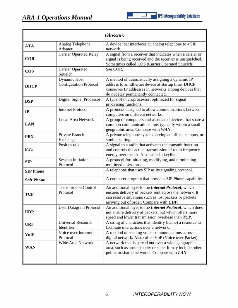
Glossary
ATA Analog Telephone
Adapter
A device that interfaces an analog telephone to a SIP
network.
COR Carrier Operated Relay A signal from a receiver that indicates when a carrier or
signal is being received and the receiver is unsquelched.
Sometimes called COS (Carrier Operated Squelch).
COS Carrier Operated
Squelch
See COR.
DHCP
Dynamic Host
Configuration Protocol
A method of automatically assigning a dynamic IP
address to an Ethernet device at startup time. DHCP
conserves IP addresses in networks among devices that
do not stay permanently connected.
DSP Digital Signal Processor A type of microprocessor, optimized for signal
processing functions.
IP Internet Protocol A protocol designed to allow communications between
computers on different networks.
LAN Local Area Network A group of computers and associated devices that share a
common communications line, typically within a small
geographic area. Compare with WAN.
PBX Private Branch
Exchange
A private telephone system serving an office, campus, or
similar setting.
PTT Push-to-talk A signal to a radio that activates the transmit function
and controls the actual transmission of radio frequency
energy over the air. Also called a keyline.
SIP Session Initiation
Protocol
A protocol for initiating, modifying, and terminating
multimedia sessions.
SIP Phone A telephone that uses SIP as its signaling protocol.
Soft Phone A computer program that provides SIP Phone capability.
TCP
Transmission Control
Protocol
An additional layer to the Internet Protocol, which
ensures delivery of packets sent across the network. It
can resolve situations such as lost packets or packets
arriving out of order. Compare with UDP.
UDP User Datagram Protocol An additional layer to the Internet Protocol, which does
not ensure delivery of packets, but which offers more
speed and lower transmission overhead than TCP.
URI Universal Resource
Identifier
A string of characters that identify (name) a resource to
facilitate interactions over a network.
VoIP Voice over Internet
Protocol
A method of sending voice communications across a
digital network. Also called VoP (Voice over Packet).
WAN Wide Area Network A network that is spread out over a wide geographic
area, such as around a city or state. It may include other
public or shared networks. Compare with LAN.
INTEROPERABILITY NOW 1-1
1 General Information
1.1 Scope
This instruction manual provides the information necessary to install and operate the ARA-1 TM
Radio-to-SIP Interface.
1.2 Description
The JPS Interoperability Solutions ARA-1 Radio-to-SIP Interface is a network device used for
interfacing radio equipment to SIP networks, thereby extending the coverage and capability of
these networks. It is comparable to an ATA (analog telephone adapter), which allows a standard
telephone to operate on a SIP network; the ARA-1 provides the same capability to a radio. The
ARA-1 makes special provision for the differences between radios and telephones. In particular,
the half-duplex nature of radios and the control signals they require are accommodated by the
ARA-1.
Designed for years of continuous operation in mission-critical applications and remote locations,
the ARA-1 has no moving parts and requires no periodic shutdown or maintenance. Startup upon
power on is typically less than 10 seconds.
1.2.1 General
The ARA-1 provides a seamless interface between a radio and an IP-based network using SIP.
This brings to existing SIP networks all of the features inherent in a radio system, including the
ability to wirelessly reach otherwise inaccessible areas. For example, an ARA-1 can be used with
an LMR system to extend the SIP Network into areas of rugged terrain, across bodies of water,
or into tunnels.
The ARA-1 also provides to radio networks all of the features available with SIP. These include
interoperable communication among disparate radio systems that is as easy as creating a typical
PBX conference call and also other PBX features such as Call Logging, Call Forwarding, and
Call Recording.
1.2.2 SIP Interface
The SIP side of the ARA-1 assigns its associated radio a unique extension that can easily be
dialed using any IP phone, softphone, or other voice communications device associated with the
SIP PBX. Any number of radios, SIP Phones, or other audio devices in the network can be
conferenced together by the SIP PBX.

ARA-1 Operations Manual
1-2 INTEROPERABILITY NOW
Alternatively, the ARA-1 can assign an IP address to its associated radio for communications
over any IP-based network or the Internet with another SIP-enabled device (such as a SIP Phone,
a softphone, or another radio/ARA-1 pair). The radio side of the interface makes full use of the
extensive suite of digital signal processor algorithms, hundreds of interface cables, and numerous
problem-solving techniques that JPS has evolved during more than a decade as the market leader
in radio interoperability.
Figure 1-1 ARA-1 Basic Block Diagram
1.2.3 Why SIP?
The main goals of modern communications system design include: convergence of voice, data,
and video; standards-based, open protocols; and individual IP addresses for all end devices.
Session Initiation Protocol, SIP, is widely seen as the preferred pathway to achieving these goals.
SIP is a signaling protocol used to create, manage, and terminate sessions in an IP-based network.
A session could be a simple two-party call or a multimedia conference session. SIP focuses on
the setup, modification, and termination of sessions allowing versatility of the format and content
of the data being shared. Since SIP is a standards-based, open protocol, SIP system operators can
pick and choose among third-party vendors when selecting existing or future applications to add
to their systems. This avoids the anti-competitive, single-vendor “lock-in” that occurs with closed
proprietary protocols.
1.3 Network Details
The ARA-1 is a 10/100BASE-T Ethernet device, and each unit has a unique Ethernet address
and an RJ-45 physical interface jack. A 10/100BASE-T device operates at either 10 or 100 Mbps
and interconnects to an Ethernet hub or switch using standard CAT 5 twisted pair cable, also
known as UTP. The maximum cable length between an ARA-1 and its hub port is 100 meters.
With the right connective equipment (recommended or supplied by JPS), the ARA-1’s Ethernet
port can be linked with virtually any LAN, WAN, or the Internet, no matter which topology or
cabling system is in use.

ARA-1 Operations Manual
INTEROPERABILITY NOW 1-3
1.4 Applications
The ARA-1 can be used either as part of a SIP PBX or without one. Often the radio associated
with the ARA-1 will be part of a repeater system. The features of each of these configurations
are explained in the following sections. It is important to read all three of the following sections
to fully understand the application of radios to SIP networks.
1.4.1 Operation within a SIP PBX
Figure 1-2 illustrates a basic ARA-1 application within a SIP PBX network. The PBX (typically
a software application running on a server) assigns extensions (associated to the IP addresses) to
each of the communications devices within the system. There can be any number of the end-user
devices (Sip Phones, softphones, analog phone/ATA pairs, or radio/ARA-1 pairs) in the PBX.
When a SIP Phone user wants to place a call to another SIP Phone, he or she can simply dial that
phone’s extension. The same process is followed to place a call to the radio: simply dial the ARA-
1’s extension. The SIP Phone user does not need to understand the esoterics of basic radio
operation; this is handled by the ARA-1.
Figure 1-2 Example of The ARA-1 in SIP PBX Network
Similarly, calls to the radio can be placed by the softphone or the analog telephone, interfaced by
the ATA, simply by entering the extension assigned to the ARA-1.
The SIP PBX can provide a multitude of functions and features that expand and enhance the
communications process. These include conferencing, voice mail, call logging, call forwarding,
and essentially any other feature available with a commercial telephone service. Because the
ARA-1 is based on the open-source SIP protocol, a wide range of PBX features are available
from a wide range of sources.

ARA-1 Operations Manual
1-4 INTEROPERABILITY NOW
NOTE: The PBX conferencing function, with multiple radio/ARA-1 pairs, provides network-based interoperability between disparate radio systems. For example, an 800 MHz trunked radio can be conferenced together with a P25 digital radio and a VHF conventional radio.
1.4.2 Operation Outside of a SIP PBX
The ARA-1 can also be used without a SIP PBX, but without the features provided by the PBX,
so that only one-to-one connections are possible. Three variations are illustrated in Figure 1-3.
The network employed can be any type of IP-based network, including the Internet.
Figure 1-3 Examples of ARA-1 Use Over Internet
The first setup in Figure 1-3 shows a connection between a SIP Phone and a radio. Without the
extensions provided by the PBX, the SIP Phone “dials” the IP address of the ARA-1. See Section
1.6 for an overview of how to initiate connections via the ARA-1 rather than by the SIP Phone.
NOTE: The radio shown in the first illustration in Figure 1-3 may be set as “receive-only” and used to monitor information and pass it over the network. For example, it may be receiving local weather or traffic reports or scanning frequencies set aside for public safety use.
ARA-1 Operations Manual
INTEROPERABILITY NOW 1-5
The second setup in Figure 1-3 shows a pair of radio systems connected via the ARA-1
technology and the network. These radio systems may be on opposite sides of the country, or
they may be collocated, but on different frequencies or bands.
The third setup shows a connection between a softphone and a radio through the ARA-1. This
operation is identical to the SIP Phone application.
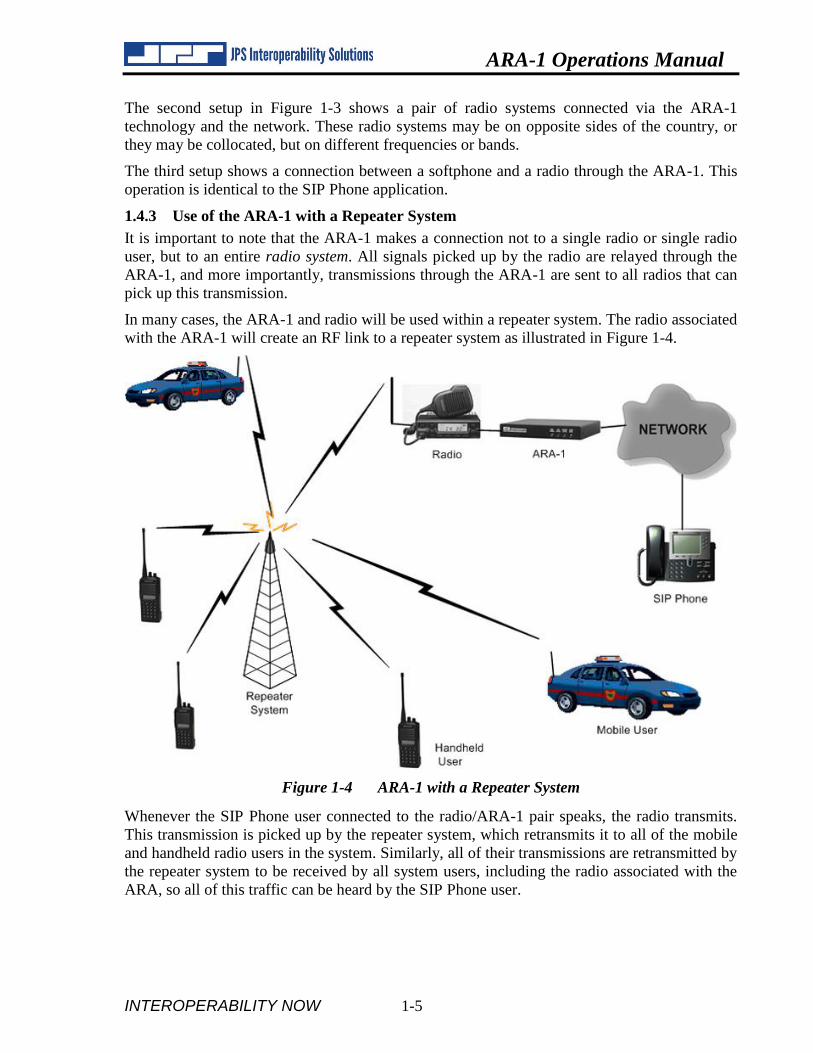
1.4.3 Use of the ARA-1 with a Repeater System
It is important to note that the ARA-1 makes a connection not to a single radio or single radio
user, but to an entire radio system. All signals picked up by the radio are relayed through the
ARA-1, and more importantly, transmissions through the ARA-1 are sent to all radios that can
pick up this transmission.
In many cases, the ARA-1 and radio will be used within a repeater system. The radio associated
with the ARA-1 will create an RF link to a repeater system as illustrated in Figure 1-4.
Figure 1-4 ARA-1 with a Repeater System
Whenever the SIP Phone user connected to the radio/ARA-1 pair speaks, the radio transmits.
This transmission is picked up by the repeater system, which retransmits it to all of the mobile
and handheld radio users in the system. Similarly, all of their transmissions are retransmitted by
the repeater system to be received by all system users, including the radio associated with the
ARA, so all of this traffic can be heard by the SIP Phone user.

ARA-1 Operations Manual
1-6 INTEROPERABILITY NOW
This concept applies to both trunked and conventional repeater systems. Note that no changes to
the repeater system are required, hence there is no installation or other downtime involved with
using the ARA-1 to create a single SIP network connection to the system, or to use multiple
ARA-1s to conference two or more radio systems together.
1.5 Connection to Devices Other Than a Radio
The ARA-1 contains all of the interface features necessary for a competent interface between a
radio and a SIP network. These features also provide a seamless interface of other four-wire
devices such as an audio console.
1.6 Initiating Connections via the ARA-1 and Associated Radio
So far calls to a radio through the ARA-1 have been described. There are three methods for
initiating a call from the radio/ARA-1 end of the connection. Each of these methods is described
in full detail in Section 4, Operation.
1.6.1 Using a Web Browser
Simply browse to the ARA-1’s IP address, select the Call Management page, enter the SIP
address or extension, and click Connect.
1.6.2 Using DTMF
If your radio has a DTMF keypad, there are two options that can be used to initiate connections
to an IP address or a PBX extension. DTMF input not terminated by a pound (#) digit invokes an
internal “speed dial” calling guide that is set up within the ARA-1; this calling guide associates
incoming DTMF sequences with the destination IP address or extension.
Whenever the DTMF input is terminated by the pound digit, the ARA-1’s Pound Terminated
Dialing feature dials the received DTMF sequence (except for the pound digit). This allows a
radio user with a DTMF keypad to dial any number or extension just as the user would dial a
regular telephone.
1.6.3 Using Squelch Breaks
The ARA-1 can use the COR (unsquelched condition) input from its associated radio as a signal
from radio system users that they want to make or end a call. The radio users in the field key and
unkey their radios at a specific cadence (user-programmable). For example, the required cadence
may be four key/unkey sequences at the specified rate (three or five will not trigger a response).
The radio associated with the ARA-1 unsquelches and re-squelches at the same cadence, and
passes this cadence on to the ARA-1. When the required cadence is detected, the ARA-1 initiates
a call to a pre-defined SIP address or extension. A COR Cadence can also be used to terminate
the call.
1.7 SIP Instructions
This manual does not attempt to familiarize the reader with SIP fundamentals. SIP is an open
protocol and there are many references that explain how to best make use of it. The ARA-1 is
fully compliant with the SIP protocol.
ARA-1 Operations Manual
INTEROPERABILITY NOW 1-7
1.8 COR & PTT Signaling in the SIP Environment
Most radio systems are either simplex or half duplex, the important aspect to remember for both
types is that only one person can be heard at a time. With full duplex systems, all parties to a
conversation may be heard simultaneously: a telephone system is a good example. Most JPS
interoperability equipment can accommodate both types of systems, but both parties of a
conversation must be using full duplex equipment for either party to be able to simultaneously
talk and listen.
The same is true of interoperable communications using SIP; many SIP devices are capable of
Full Duplex operation (as are most phone-related voice communications devices). However,
when patched to a half-duplex radio, the conversation is limited to Half Duplex.
COR: A signal that tells when a radio (or other communications device) is receiving a valid signal (an output from the device).
PTT: A signal that tells a radio (or other communications device) that a valid signal is being sent to be transmitted (an input to the device).
Full Duplex: System users can simultaneously talk to and listen to other parties of the communications system.
Simplex or Half Duplex: Only one system user can be heard at a time.
This section will help explain how these concepts affect the set up configuration options. More
details on the options in Section 2.
1.8.1 COR Handling in the SIP Environment
There are three basic components:
How the ARA-1’s radio interface determines that its associated radio is unsquelched-
how the “Active COR” condition is determined. Also called “Deriving COR.”
How this signal is sent over the network by the SIP Protocol
How the SIP device on the “other side” of the network knows that valid audio is being
sent to it.

ARA-1 Operations Manual
1-8 INTEROPERABILITY NOW
1.8.2 Deriving COR from the Local Radio
Within the JPS ARA-1 SIP-to-Radio interface, there are two options at the radio interface for
deriving COR (determining that the associated radio is unsquelched).
See Figure 1-5 below; with ARA-1s on both sides of the link, it illustrates all aspects of COR/PTT
signaling. To simplify the explanation, consider Radio A the Local Radio; Radio B will be
referred to as the Distant Radio.
Figure 1-5 Radio to ARA-1 to IP Network to ARA-1 to Radio
Currently we’re discussing how the Local ARA-1 determines that the Local Radio cabled to it is
unsquelched. The options include:
A Hardwired COR signal – some radios supply a COR output line.
VOX: Active COR is triggered by any audio input above a configurable threshold.
For radio interface cables supplied by JPS, the Radio Application Note supplied with the cable
will explain which is best for the associated radio model.
1.8.3 Pushing the COR Indication across the IP Network
The Local ARA-1 in Figure 1-5Error! Reference source not found. has various options for
making the Distant ARA-1 aware that the local radio is unsquelched. These include:
RTP Header: IP packets include an RTP extension header that JPS created for this
purpose. When the extension is detected by the distant ARA-1, it knows the local radio
is unsquelched. The local ARA-1 will send its COR status over the network as part of the
RTP extension header if its Send Radio COR/AUX Status function is enabled.
Silence Suppression: Very simply described – send audio packets to the distant ARA-1 if
the local radio is unsquelched, and if not, don’t send any. Silence suppression is invoked
when the Silence Suppression function is enabled via the SIP Settings web page.
These Active COR indicators are best understood in terms of how they are applied by the Distant
ARA-1. Operation at this unit is more complex as the Distant ARA-1 must also be able to
function properly if there are “non-JPS” devices playing the part of the Local ARA-1. This is
vital because many SIP devices, such as the SIP VoIP phones and computer-based Softphones
are Full Duplex, while radio systems are Half Duplex. If not handled properly, a Full Duplex
device that’s linked to a distant radio could cause that radio to remain continuously keyed. This
is not likely to be a desirable condition.
ARA-1
LocalRadio A
Local
ARA-1
Distant
Radio B
Distant

ARA-1 Operations Manual
INTEROPERABILITY NOW 1-9
1.8.4 Deriving COR at the Distant Side
The options are different at the network interface; that is - how an ARA-1 determines that the
radio at the other side of the network is unsquelched. These are the options for deriving COR at
the unit’s network interface – how, in Figure 1-5, the distant ARA can determine that the local
radio is unsquelched:
VOX: triggered by any audio input (audio coming over the network) above an adjustable
threshold level.
VMR: triggered by audio input ONLY if that audio has content (again above an adjustable
threshold), that correlates to human speech sounds and patterns. VMR can help prevent
false transmitter activation from background noise on the SIP connection (such as
someone breathing heavily into a SIP Phone handset mouthpiece, or someone using a SIP
Phone in a high ambient noise environment)
[Note: VMR requires significant processing resources. This is why VMR is supported
only on the network side and not on the radio side.]
RTP Header: makes use of an RTP extension header that JPS created for this purpose.
This is useful when there are JPS SIP devices at both ends (or the use of the SIP extension
header has been built in to another vendor’s equipment).
The JPS SIP devices also allow combinations of the above; these are useful when there
may be different types of SIP devices in the system. When a combination is invoked - for
example “RTP Header + VMR” - the ARA-1 will use the RTP Header if it’s available
and the VMR function when it’s not.
Packet COR: Heeding the note below, this is the preferred method, and the combination
of Silence Suppression and Packet COR was made part of the NIST BSI specification
(JPS SIP interfaces are BSI compliant). With this method, the Local ARA -1, upon
determining that its associated local radio is squelched, will discontinue sending audio
packets (Silence Suppression). Regarding the Distant ARA's PTT function, it will activate
PTT to the distant radio only while receiving audio packets from the network.
Note: Packet COR should only be used if all SIP devices on the network use Silence
Suppression. If a link is made to any SIP device configured otherwise, that distant device
will continue to send audio packets over the network even when there is no valid audio
signal, and the PTT function of an ARA-1 set to Packet COR will therefore stay activated,
holding the local radio in transmit mode.

ARA-1 Operations Manual
1-10 INTEROPERABILITY NOW
1.9 Specifications
Table 1-1 Specifications
Radio RX Audio Input
Input Impedance Balanced 47k ohms, transformer coupled
Input Level Incoming signals adjustable from –30 to +11 dBm to set 0 dBm nominal input;
+15 dBm clipping; +20 dB boost configurable
Frequency Response 10 Hz to 3600 Hz +/- 2dB
Radio TX Audio Output
Output Impedance Unbalanced 600 ohms, AC Coupled
Output Level Adjustable from –30 to +11 dBm, 0 dBm nominal factory default; +9 dBm
clipping into a 600 ohm load
Frequency Response 10 Hz to 3350 Hz +/- 2dBm
Distortion 0.5% or less (excepting Vocoder)
Radio COR and AUX Inputs
Input Impedance 47k ohm pull-up to +5V
Polarity COR: Selectable active low or active high; AUX Inputs: Active low
Threshold +2.5V nominal
Protection Up to + 100 VDC
Radio PTT and AUX Outputs
Output Type Open drain, 47k ohm pull-up to +5V
Maximum Sink Current 100 mA
Max Open Circuit Voltage +60 VDC
Network Interface
Interface Type 10/100BASE-T Ethernet, 10 or 100 Mbps; RJ-45 Connector
Protocols SIP, SDP, RTP, STUN
Audio Vocoder Selectable, 13 or 64 Kbps data rate
General/Environmental
Programming/Configuration Web, Telnet, or RS-232 Interface
Front Panel Power, Link Active, Channel Active, and Audio Level LEDs
Rear Panel Audio/Data, Serial, Network, and Power Connectors
Audio/Data Connector DB-15 Female
Input Power (12 VDC Nom) +11 to +15 VDC at 0.5A max. 12VDC (wall-cube supplied)
Power Connector Coaxial Jack, 2.5 mm ID, 5 to 5.5 mm OD; Center Pin Positive; Reverse
Polarity Protected
Size and Weight 1.3”H x 8.3”W x 6.7”D (3.3 x 21.1 x 17.0 cm); 1.1 lbs. (0.5kg)
Temperature Operating: -20 to +60 degrees C; Storage: -40 to +85 degrees C
Humidity Up to 95% at 55 degrees C
Regulatory Compliance
FCC part 15 RFI Emissions for USA
CE/TUV Emissions, Immunity and Safety for Europe, USA, Canada

ARA-1 Operations Manual
INTEROPERABILITY NOW 1-11
1.10 Equipment and Accessories Supplied
Table 1-2 Equipment and Accessories Supplied 120 VAC Version
ARA-1 Shipping Level - JPS P/N 5060-800000
Quantity Item JPS P/N
1 ARA-1 Final Assembly
Includes the ARA-1 enclosure with the ARA-1 PCB Assembly
5060-801000
1 DC Power Supply [100 to 240 VAC, 47-63 Hz to +12 VDC, 500 mA] 1620-120600
1 Operation and Maintenance Manual 5060-800200
1 Accessory Kit 5060-800150
Consisting of:
Qty Part Number Description
1 0313-070000 Network Cable, 6 ft.
1 0313-080515 Audio Crossover Adapter
(for use with JPS radio interface cables)
1.11 Optional Equipment: Not Supplied
Table 1-3 Optional Equipment - Not Supplied
Description JPS P/N
Generic Radio Interface Cable; unterminated at radio end; 15 ft. 5961-291115
Interface cables for a very wide range of commercial radios are available for purchase.
Email JPS or consult the JPS Interoperability Solutions website for a listing:
Email: [email protected] / [email protected]
www.jpsinterop.com
End of Section 1

ARA-1 Operations Manual
1-12 INTEROPERABILITY NOW
This page intentionally blank

INTEROPERABILITY NOW 2-1
2 Installation
2.1 General
This section provides the instructions for unpacking, inspection, installation, and setup. Also
included are directions for reshipment of damaged parts or equipment.
2.2 Unpacking and Inspection
After unpacking the unit, retain the carton and packing materials until the contents have been
inspected and checked against the packing list. If there is a shortage or any evidence of damage,
do not attempt to use the equipment. Contact the carrier and file a shipment damage claim. A
full report of the damage should also be reported to the JPS Customer Service Department. The
following information should be included in the report:
Order Number
Equipment Model and Serial Numbers
Shipping Agency
Date(s) of Shipment
The JPS Interoperability Solutions Customer Service Department can be reached by phone at
(919) 790-1011, or by FAX at (919) 865-1400, or email at [email protected]. Upon receipt
of this information, JPS will arrange for repair or replacement of the equipment.
2.3 Reshipment of Equipment
If it is necessary to return the equipment to the manufacturer, an RMA (Returned Material
Authorization) number must first be obtained from JPS. This number must be noted on the
outside of the packing carton and on all accompanying documents. When packing the unit for
reshipment, it is best to use the original packaging for the unit; if this is not possible, make sure
that adequate packing material is used to prevent excessive shocks during transport and handling.
Shipment should be made prepaid consigned to:
JPS Interoperability Solutions
Customer Service Department
5800 Departure Drive
Raleigh, North Carolina 27616
USA
Plainly, mark with indelible ink all mailing documents as follows:
GOODS RETURNED FOR REPAIR
Mark all sides of the package:
FRAGILE - ELECTRONIC EQUIPMENT
Inspect the package prior to shipment to be sure it is properly marked and securely wrapped.

ARA-1 Operations Manual
2-2 INTEROPERABILITY NOW
2.4 Installation Overview
NOTE: ARA-1 installation requires knowledge of Ethernet network fundamentals as well as a basic understanding of IP (Internet Protocol). As with any network-connected device, improperly configuring and installing the ARA-1 could disrupt proper network operation. Please seek the assistance of your network administrator or other knowledgeable person if you are unsure about how your network is configured.
Four steps are needed to properly install the ARA-1. These steps are:
1. Determine the desired IP address, subnet mask, and (if applicable) the gateway
address for the unit. You may have to contact the network administrator for your
organization to obtain this information.
NOTE: Operation of the ARA-1 is not possible without this information.
2. Provide the proper primary power for the unit.
NOTE: Use only the Class 2 power supply provided with the equipment.
REMARQUE: Utilisez seulement la Class 2 de la generation electrique qui est inclus avec l'equipement.
.
3. Interconnect the unit with the communications system via the ARA-1's rear panel
connectors. J7 provides the audio and control lines necessary to interface the ARA-1
to your audio equipment. Radio interface cables for most common makes and models
can be purchased from JPS Interoperability Solutions.
4. Configure the unit’s operational parameters per Sections 2.8.3 (rear panel audio level
adjustments) and 3.2 (system configurations set by web browser).

ARA-1 Operations Manual
INTEROPERABILITY NOW 2-3
2.5 Installation Considerations
Careful attention to the following installation suggestions should result in the best unit/system
performance. Figure 2-1 provides overall unit dimensions.
The ARA-1 must be installed in a structure that provides both protection from the weather and
assurance of ambient temperatures between -20 and +60 degrees C. Since the unit is neither
splash proof nor corrosion resistant, it must be protected from exposure to salt spray. When the
unit is mounted in a cabinet with other heat-generating equipment, the use of a rack blower is
suggested to keep the cabinet interior temperature within specifications.
NOTE: If the ARA-1 is installed in a high RF environment such as a repeater system or other transmitter site, it is recommended that all cable assemblies be individually shielded, with the shield grounded to the ground pin on the terminal block for that module. For all D-subminiature connector cable assemblies, cable shields should be connected to connector shells so that they make contact with the grounded D-subminiature connector shells on the ARA-1.
NOTE: For the DC input, the plug is the equipment disconnect device. REMARQUE: Pour deconnecter le DC, retirez la prise qui est couramment connecte a l'equipement

ARA-1 Operations Manual
2-4 INTEROPERABILITY NOW
Figure 2-1 Outline Dimensions

ARA-1 Operations Manual
INTEROPERABILITY NOW 2-5
Figure 2-2 Front and Rear Panel Views
ARA-1 Operations Manual
2-6 INTEROPERABILITY NOW
2.5.1 Internal Configuration
There are no internal user-configurable components, switches, or other controls. There should be
no need to ever open the ARA-1 case.
2.6 Power Requirements
The ARA-1 is designed to operate from a nominal +12V DC supply. The unit will meet all of
its specifications over a voltage range of +11 to +15 VDC and will be damaged by a DC source
that delivers a constant (non-transient) DC voltage above this range. The DC power consumption
is 500 mA maximum. The AC adapter provided with the unit meets these specifications.
NOTE: Use only the Class 2 power supply provided with the equipment.
REMARQUE: Utilisez seulement la Class 2 de la generation electrique qui est
inclus avec l'equipement.
The ARA-1 is a microprocessor-controlled device. As with any such equipment, a very short loss
of power can cause operational problems and/or cause the unit to reset. The communications link
will be inoperable during the reset period. JPS recommends the ARA-1 and associated equipment
be connected to an AC power source that utilizes a UPS (uninterruptible power system). If the
overall site does not have UPS capability, the ARA-1 should be plugged into a smaller UPS, such
as those used for personal computer systems.
2.7 Installation Checklist
Table 2-1 Basic Installation Checklist
Determine ARA-1 network parameters
such as IP address, subnet mask, and
gateway address.
You must assign these values. If you are not sure
how to determine these values, see the network
administrator for your organization.
Provide suitable power for the device. See Section 2.6.
Make interconnections. See Section 2.8.
Adjust audio levels. See Section 2.8.3.
Configure ARA-1 parameters. See Section 3.
2.8 Rear Panel Adjustments and Connectors
Refer to Figure 2-2 for a view of the ARA-1 rear panel. All rear panel connectors and adjustment
potentiometers are explained below, starting at the left side of the panel.
2.8.1 DC Input Connector (J6)
The ARA-1 operates on a nominal +12 VDC. The power is applied through J6 via the “wall
cube” AC adapter provided with the unit.
2.8.2 Connection to Radio or Other Four-Wire Device (J7)
The interface between the ARA-1 and associated radio or other audio device is made via J7
(Audio/Control) on the rear panel. J7 is a female DB-15 connector.
ARA-1 Operations Manual
INTEROPERABILITY NOW 2-7
Table 2-2 ARA-1 Pinout (J7)
PIN Signal Description
1 Ground Ground connection
2 N/A Not used
3 /AUX In 0 Auxiliary Input 0 - Active low
4 /AUX Out 0 Auxiliary Output 0 - Active low
5 Ground Ground connection
6 Audio Input Balanced audio input
7 Analog Ground Analog ground
8 Audio Output Unbalanced Audio output
9 N/A Not used
10 /AUX In 1 Auxiliary Input 1 - Active low; general purpose
11 /AUX Out 1 Auxiliary Output 1 - Active low; general purpose
12 /COR Input Input from radio COR, programmable active high or low
13 /PTT Out Output to radio PTT, active low, open drain
14 Audio Input Balanced audio input
15 Analog Ground Analog ground
NOTE: To interface unbalanced “single-ended” audio, connect the audio to one of
the two balanced audio inputs and ground the other. Interface cables purchased
from JPS handle the unbalanced/balanced audio issue properly.
2.8.3 Audio Level Adjustment Potentiometers and Input Test Point
The audio input level to the ARA-1 is set by adjusting the IN LVL control on the rear panel. With
“normal radio receive audio” input applied at J7, adjust the IN LVL control until the AUDIO
INPUT indicator flashes on voice peaks.
NOTE: “Normal radio receive audio” means the audio output that results when receiving a fully-quieted (on frequency) speech signal from someone talking at a typical speaking volume.
The OUT LVL control sets the audio output level from the ARA-1 and may be adjusted to the
level suitable for the equipment connected to the unit. If necessary, the input audio level can be
further boosted within the unit’s software (see Section 3.3.6).
A test probe may be inserted into the test point to measure the level of the incoming audio. The
proper audio input level may also be set by connecting an AC voltmeter to the test point TP1 on
the real panel and adjusting the IN LVL control for an average audio level of about 0.2V or –
12dBm.

ARA-1 Operations Manual
2-8 INTEROPERABILITY NOW
NOTE: An Audio Crossover Adapter, part number 0313 080515, is included with the ARA-1. This DB-15 male to DB-15 female adapter allows the use of radio cables developed specifically for the JPS ACU-1000 Intelligent Interconnect system to be used with the ARA-1. It provides a crossover of transmit and receive audio, as well as COR and PTT control signals. You only need this adapter if you are planning to connect a radio to the ARA-1 using a JPS designed or manufactured radio interface cable. The adapter makes the ARA-1 audio connector pinout match the one found on the ACU-1000. If you are designing a cable based on Table 2-2, or if you are connecting the ARA-1 directly to an ACU-1000, then you do not need the Audio Crossover Adapter.
2.8.4 Network Connection (J3)
The ARA-1 is connected to the Ethernet network via rear panel connector J3 using a standard
RJ-45 Ethernet Patch Cable (non-crossover). A six-foot long cable is included with the unit.
2.8.5 Serial Port Connection (J4)
J4 is a standard RS-232 DCE serial port. It is a female DB-9 connector, and can be interfaced to
most PCs, typically standard DTE serial ports, using a DB-9 straight-through serial cable (not
included with the ARA-1).
NOTE: This connector is used only during factory setup.
Table 2-3 J4 Serial Port Pinout
J4 pin Description
2 TX data
3 RX data
5 Ground
End of Section 2

INTEROPERABILITY NOW 3-1
3 Configuration
3.1 General
This section explains all settings and level adjustments that configure the ARA-1 other than the
rear panel potentiometer audio level adjustments described in Section 2.8.3. It is not necessary
to remove the ARA-1 cover to configure the unit.
The instructions are broken down into two main sections:
Interfacing the unit to the SIP network
Interfacing the unit to a radio or other four-wire device
3.2 Configuration Details: Network Interface
Configuration is performed by connecting to the unit’s IP address with a web browser.
The ARA-1 comes from the factory configured with the following default settings:
IP Address: 192.168.1.200
Subnet Mask: 255.255.255.0
Gateway IP: 0.0.0.0
If these settings are compatible with your network, you may plug the ARA-1 into your Ethernet
switch and proceed with the configuration. If you wish to configure the ARA-1 with a standalone
computer, you should set your computer’s network settings to allow communication with these
defaults. See your network administrator if you need assistance with your computer settings.
NOTE: If you connect your computer directly to the ARA-1 (without an Ethernet switch), you will need to use an Ethernet crossover cable instead of a standard Ethernet cable.
NOTE: To restore the factory default conditions, depress the rear panel switch SW1 (DEFAULTS) for 5 seconds while unit power is on. All parameters (including the unit’s IP address) will be returned to JPS factory defaults. Any previously assigned user parameters will be lost during this process.

ARA-1 Operations Manual
3-2 INTEROPERABILITY NOW
3.2.1 Basic Unit Status and Information
Apply power to the ARA-1, connect your Ethernet cable, and start a web browser on your
computer. Enter 192.168.1.200 in the address field of your browser (or other IP address if the
unit’s configuration has been changed). If your settings and connection are correct, you should
see the page shown in Figure 3-1.
Figure 3-1 Status/Information Page
This is the status and information page for the ARA-1 and the page you are greeted with when
you browse to the unit. It shows the current network settings as well as some other status
information, such as the version of the firmware currently loaded in the ARA-1. Now click the
Network Settings link to go to the next page.

ARA-1 Operations Manual
INTEROPERABILITY NOW 3-3
3.2.2 Network Settings
The Network Settings page is where all network parameters are set.
Figure 3-2 Network Settings Page
If you select Static from the Boot Protocol drop-down menu, then you must adjust the other
settings to match your particular network. If you select DHCP as your boot protocol, then your
local DHCP server will assign these values for you. When you have made any necessary changes,
click Save at the bottom of the page. These settings are not actually applied until the unit is
restarted, so you can continue to make other changes if necessary. Now click on SIP Settings for
the next page.
3.2.3 SIP Settings
The SIP Settings page is where you will configure the SIP settings for this device. The ARA-1
can register with a SIP PBX, or it can operate as a standalone device.
Note that theARA-1 settings will most often depend on the requirements of the SIP
communications device/system that the ARA-1 is being connected to.

ARA-1 Operations Manual
3-4 INTEROPERABILITY NOW
Figure 3-3 SIP Settings Page
The settings shown in Figure 3-3 are the same ones that would be set for any SIP endpoint such
as a SIP Phone. An exception is the Send Radio COR/AUX Status setting. If set to Enable, the
status of the COR and AUX Input pins on the ARA-1 rear panel will be sent across the IP link.
This is useful if your radio has a hardware squelch line (COR) and you are linking to other ARA-
1 units. Sending COR Status will tell the other units when the radio is unsquelched, and the other
radios can assert their PTT control output lines if they are part of the connection. This is a more
sure and timely method than the use of VOX or VMR as the network audio gating function at the
other ARA-1 units. See also Section 3.3.5.

ARA-1 Operations Manual
INTEROPERABILITY NOW 3-5
Table 3-1 SIP Settings Options
Settings Option Description
Display Name: The name displayed on a remote SIP Phone when it connects to the ARA-
1.
Domain: The unit’s SIP domain (if needed). The domain portion of the unit’s URI.
Username: The SIP user name or extension. The username portion of the unit’s URI.
Password: The password used for authentication when required.
Auth ID: The user ID used for authentication when required and different from the
username.
Proxy: SIP proxy server address. Can be a name (e.g. mysip.com) or IP address.
Proxy Port: The port number of the specified SIP proxy server.
Outbound Proxy: SIP proxy server used for outbound calls if separate from the primary SIP
proxy used for registration.
Outbound Proxy Port: The port number of the specified outbound SIP proxy server.
Register: Enable/disable registration with SIP proxy server.
Registration
Expiration:
Time interval between successful registrations with the SIP proxy.
SIP Port: The local port number for SIP packets. Usually same as the Proxy port.
RTP Port: The local port number for RTP packets.
RTP TOS: Value to set in RTP packet TOS IP header field for QOS applications.
Use STUN: Enable/disable the use of STUN to discover the device’s external IP
address.
External IP: Hard coded external IP address to use.
STUN Server: The name or IP address of the STUN server to use.
STUN Port: The port number of the STUN server.
Send Keep Alives: Enable/disable the sending of SIP keep alive packets.
Keep Alive Interval: Interval (in seconds) to send SIP keep alive packets.
Answer Incoming Calls: Allows the unit to ignore incoming calls or answer them automatically.
Answer Incoming
Delay:
Allows the unit to wait for the specified amount of time (0 to
30,000 msec) before answering an incoming call.
DTMF Mode Mode to use for sending DTMF during a call.
ARA-1 Operations Manual
3-6 INTEROPERABILITY NOW
Table 3-1 SIP Settings Options
Block DTMF In-Band: Block DTMF in the audio stream when using a DTMF Mode other than
In-Band.
Preferred Codec: The voice compression type the ARA-1 offers for outgoing calls.
Available options: 13 kbps GSM or 64 kbps G.711u (default).
Silence Suppression: If disabled, packets will be sent even during audio silence.
Loss of Media
Detection:
Action to take when a loss of the media stream is detected during a call.
Options are Disable (do nothing), Disconnect Immediately (hang up the
call), or reINVITE then Disconnect (Send a reINVITE to try to
reestablish the call and then hang up if that fails).
Loss of Media Timeout: Number of seconds media is lost before performing the configured action.
Send Radio COR/AUX
Status:
If enabled, COR/AUX input status will be sent via the RTP extension
header.
When the SIP settings have been entered, click Save at the bottom of the page. Then click SIP
Actions for the next page.

ARA-1 Operations Manual
INTEROPERABILITY NOW 3-7
3.2.4 SIP Actions
SIP Actions is a mechanism by which the hardware outputs of the ARA-1 (PTT, AUXOUT0, and
AUXOUT1) may be controlled by a remote SIP endpoint. If so configured, the proper DTMF
sequence, when detected by the ARA-1’s network interface, will turn these outputs on or off.
Use the SIP Actions page (shown in Figure 3-4) to configure these DTMF sequences.
The DTMF Digit Timeout entry determines how the ARA-1 decides whether a detected DTMF
digit is part of the current DTMF sequence or the start of a new one. If the time between the end
of one digit and the start of the next is less than the DTMF Digit Timeout, that character will be
considered part of the current DTMF sequence and appended to the digits already detected. As
soon as a pause is measured that is longer than the timeout entry, the current DTMF sequence
will be considered complete. The factory default setting—a duration of one second (1000 ms)—
should work for most systems.
In order to control the PTT output of the ARA-1 using SIP Actions, the Network COR Type
setting on the Radio Settings page (see Figure 3-5) must be set to SIP Actions.
Figure 3-4 SIP Actions Page

ARA-1 Operations Manual
3-8 INTEROPERABILITY NOW
3.3 Configuration Details: Radio Interface
Figure 3-5 Radio Settings Page
Included on the Radio Settings page (shown in Figure 3-5) are all the settings that affect the
interface to, and operation of, the radio cabled to the ARA-1. This page is used to configure and
optimize the unit for best performance in a particular radio application. Each of the settings is
explained in this section; the default settings are shown in Figure 3-5.
Please see also Section 1.8 “COR & PTT Signaling in the SIP Environment.”
3.3.1 Radio COR Settings Options
The ARA-1 must know when its associated radio is receiving a valid signal; it uses this to
determine when it should send whatever audio is present on the radio’s receive audio output lines
across the SIP network. The Radio COR settings all ensure that this function is optimized.
ARA-1 Operations Manual
INTEROPERABILITY NOW 3-9
3.3.1.1 Radio COR Type
The Radio COR Type setting determines which method the ARA-1 will use to determine when
the radio is receiving a valid signal, then the radio/ARA-1 pair will be put into the unsquelched
mode [also called “open squelch”] and send the radio RX audio to the SIP network. The ARA-1
can either use the COR output signal from the radio or use VOX (see Section 3.3.1.3). The COR
output is a control signal from the radio that activates when the squelch opens. If this line is
available, connect it to the ARA-1 COR input and select ACTIVE HIGH or ACTIVE LOW,
depending on whether this line asserts a voltage when the radio is receiving (active high) or pulls
to ground when receiving (active low). This control line may also be called COS or simply
SQUELCHED or UNSQUELCHED.
If the radio does not have a COR output control line, select VOX. When the ARA-1 is in VOX
mode, it measures the volume of the sound available in the RX output from the radio. Whenever
this audio exceeds a set threshold, the VOX trips, signaling the unsquelched condition (see Radio
COR VOX Sensitivity, Section 3.3.1.3). When using the VOX mode, adjust the squelch on the
radio so that no noise is produced unless the radio is actually receiving a signal. FM radios that
are running at full “open squelch” output a high volume of noise when there is no carrier present,
and this noise will inappropriately trip the VOX function.
NOTE: The Applications Notes that are provided with radio interface cables purchased from JPS will identify whether a COR line is available, and if so, whether its sense is active high or active low.
3.3.1.2 Radio COR Inhibit Time
In some radios, the COR line activates momentarily when the radio reverts to receive from
transmit. Even if a hardware COR line is not being used, the radio may produce a burst of audio
when going from the transmit state to a squelched receive state. This “false COR” can cause
problems in some applications, so the ARA-1 includes a provision to ignore the COR signal for
a specified period of time. In many cases this provision is not needed.
The ARA-1 front panel CHANNEL ACTIVE LED is lit whenever the ARA-1 has detected active
COR or its VOX function has been tripped. If this LED flashes whenever the radio drops out of
transmit mode, raise the COR Inhibit time until this no longer occurs. See also Ping Pong,
explained in Section 5.7.
3.3.1.3 Radio COR VOX Sensitivity
The Radio COR VOX Sensitivity setting adjusts the sensitivity of the audio-activated COR
system, also called VOX (Voice Operated Switch). The sensitivity should be set to the lowest
value that always causes the VOX to trip during speech signals from the radio. Setting to a higher
sensitivity will increase the likelihood that the unit will “false,” that is, unsquelch inappropriately
due to noise or other invalid sounds. Make sure the radio RX audio level is set properly before
you adjust the VOX Sensitivity.

ARA-1 Operations Manual
3-10 INTEROPERABILITY NOW
3.3.1.4 Radio COR VOX Hang Time
When using VOX as the Radio COR Type, the system depends on the presence of audio to
consider a signal present. Since speech is not continuous (there are pauses in it), the VOX system
must “hang,” or wait for a certain period of time, before making the determination that the signal
is no longer present, otherwise it will resquelch momentarily between syllables or during short
pauses in speech. Set the Radio COR VOX Hang Time to the lowest level that does not create
inappropriate resquelching. The ARA-1 front panel CHANNEL ACTIVE LED is lit whenever the
ARA-1 has detected active COR from the radio or its Radio VOX function has been tripped. If
this LED flashes during pauses in speech from the radio, the hang time must be increased.
3.3.2 Radio PTT Timeout
The Radio PTT Timeout option sets the maximum amount of time (in seconds) that the ARA-1
will continuously assert PTT. Its purpose is to protect the radio’s transmitter from damage as
well as to prevent radio users from being locked out by a “hung” PTT. When the PTT timeout
triggers, the original source of the PTT (Network COR) must clear (de-activate) before that
source will be allowed to again activate the ARA-1’s PTT output to the radio.
For example, if a user is connected to an ARA-1 via a SIP Phone, and the ARA-1 is configured
to use VMR as the Network COR Type, an overly sensitive SIP Phone microphone and/or loud
background voices can cause the ARA-1 to key indefinitely, thereby preventing any return
communications from radio users. The PTT Timeout will trigger after the set amount of time has
passed, unkeying the associated radio regardless of network audio content. Furthermore, the
ARA-1 will not allow network audio input to key the radio again until there is a break in the
network COR signal generated by the VMR function.
3.3.3 COR Priority
Since radios are half-duplex devices (you can either talk or listen, but not both at the same time),
the possibility exists that the radio may be receiving a signal at the same time a signal is being
received from the SIP network. The COR Priority setting allows the user to select which one has
priority. When set to Radio Priority, the radio RX audio takes precedence. That is, if the radio is
unsquelched (COR active), audio from the network will not put the radio into transmit mode until
the radio squelches (COR inactive). This means that people communicating via radios will have
precedence over communications coming in via the SIP network.
When set to Network Priority, valid audio from the network will key the radio associated with
the ARA-1 regardless of any RF signals being received by the radio.
For applications where full-duplex operation is desired, set this option to Disable. In this case,
neither the radio COR nor network COR will take priority, allowing both to pass through
unabated.
3.3.4 Always Pass Audio
By default, the ARA-1 will only pass audio from the radio interface to the network interface or
vice versa when the appropriate COR is present. In some applications, it may be desirable to have
audio pass through regardless of COR status, such as in full-duplex systems. Use the Always Pass
Audio option to enable audio pass through. Be sure you understand the concept of Silence
Suppression as it relates o COR/PTT before modifying, particularly for half-duplex systems.

ARA-1 Operations Manual
INTEROPERABILITY NOW 3-11
3.3.5 Network COR Settings Options
Network COR settings define how and when the audio coming from the network is seen to be
valid and, therefore, will cause the associated radio to “key up” and transmit this audio. Also
affecting this is the COR Priority setting, which decides which has precedence—the radio or the
network—when valid audio is being received from both simultaneously (see Section 3.3.3).
Note: Packet COR/Silence Suppression is the preferred method, but requires that both Packet
COR and Silence Suppression are used by all SIP devices in the system.
Please see also Section 1.8 “COR & PTT Signaling in the SIP Environment.”
3.3.5.1 Network COR Type
The Network COR Type function is similar to Radio COR Type except that there are more options.
This setting tells the ARA-1 how to determine when there is a signal coming from the SIP
network, which will ultimately activate the attached transmitter. VOX senses the audio level,
while VMR (Voice Modulation Recognition) looks specifically for human speech and ignores
non-speech signals. VMR can help prevent false transmitter activation from background noise
on the SIP connection (such as someone breathing heavily into a SIP Phone handset mouthpiece,
or someone using a SIP Phone in a high ambient noise environment).
The RTP Header, RTP Header + VOX, and RTP Header + VMR options may be useful if multiple
ARA-1 units are integrated in the SIP network. These COR types make use of the ARA-1 RTP
extension header that sends the unit’s COR status to other ARA-1s that they are conferenced
with. This is helpful as these other ARA-1s will receive a positive indication of COR status that
arrives coincidentally with the radio audio, and the ARA-1 will not have to derive the COR status
using a VOX or VMR function. This is a quicker and surer way to determine when the linked
ARA-1s should key their associated transmitters. For these settings to have any utility on the unit
being configured to use them, another ARA-1(or other SIP device) that may link to this unit must
send the RTP Header. If the device on the other side of the network is another ARA-1, it must
have its SIP Settings Send Radio COR/AUX Status option enabled. See Section 3.2.3 for
instructions about enabling this function.
To further clarify, when Radio A is linked to Radio B over a SIP network via a pair of ARA-1s,
whenever Radio A is receiving a valid signal (and, therefore, has active COR), Radio B should
have its PTT activated so that it can retransmit the audio received from Radio A. If the ARA-1
associated with Radio A has the Send Radio COR/AUX Status function enabled, it will send its
COR status over the network as part of the RTP extension header. The ARA-1 associated with
Radio B can make use of this information only if its Network COR Type is set to one of the
following:
RTP Header
RTP Header + VOX
RTP Header + VMR
Use the RTP Header setting if all end-devices on the system are connected via ARA-1s or other
SIP interfaces that support the RTP Header. For example, if there will only be two radios
connected over the Internet (see the center diagram of Figure 1-3). When the Network COR Type
is set to RTP Header, the only method used to validate network audio (and hence key the
associated radio) is the COR information transferred in the RTP extension header. This means
that the ARA-1 will ignore network audio from other devices not interfaced by an ARA-1 with
ARA-1 Operations Manual
3-12 INTEROPERABILITY NOW
its Send Radio COR/AUX Status function enabled (for example, a SIP Phone). If these other
devices will be used, set the ARA-1 Network COR Type to either RTP Header + VOX or RTP
Header + VMR.
Both RTP Header + VOX and RTP Header + VMR make use of the COR status information from
linked ARA-1s, but also properly link with non-ARA-1 devices. When either of these modes is
selected, the ARA-1 will use both functions (the COR status or VOX; the COR status or VMR)
to validate network audio. Select between these two options using the same reasoning as you
would when choosing between VOX and VMR.
NOTE: The RTP extension header used to transfer COR/AUX status is not part of the full common standard and, therefore, there is a possibility that another SIP device may be using this header for some other purpose. Two conditions may result:
(1) An incompatible SIP device will misinterpret the COR/AUX extension header sent from the ARA-1. Most likely, the device will interpret the status information as audio. Clicking noises may result in the device’s audio output.
(2) An incompatible SIP device will send a non-standard RTP extension header that is misinterpreted by the ARA-1. This may cause the ARA-1 to signal the associated radio to key inappropriately.
Use the following guidelines when deciding which Network COR types to use:
If all end devices are radios interfaced by ARA-1s, use RTP Header as the Network COR
type in all ARA-1s and enable the Send Radio COR/AUX Status SIP setting in all ARA-
1s.
If the network consists of mixed devices, for example, multiple ARA-1 units as well other
SIP devices such as SIP Phones or softphones, and these devices have no
incompatibilities with SIP extension headers use either RTP Header + VOX or RTP
Header + VMR as the Network COR type in all ARA-1s and enable the Send Radio
COR/AUX Status SIP setting in all ARA-1s.
If the network consists of mixed devices, for example, multiple ARA-1 units as well other
SIP devices such as SIP Phones or softphones, and these devices have SIP extension
header incompatibilities, do not use any of the Network COR Types that include RTP.
Instead use one of the other settings as the Network COR type in all ARA-1s and disable
the Send Radio COR/AUX Status SIP setting in all ARA-1s.
The next setting—SIP Actions—should be selected when controlling the ARA-1’s PTT output
via DTMF over the network. See Section 0 for instructions on how to configure SIP Actions.
The next network COR type option is Packet. When Packet is selected, the ARA-1’s decision as
to when to key the radio is based upon the presence or absence of audio RTP packets. When the
ARA-1 is receiving audio RTP packets, it will activate PTT and key the radio. When it stops
receiving audio RTP packets, it will deactivate PTT thus unkeying the radio. This feature must
be used in conjunction with silence suppression on the remote device.
When Packet COR is enabled, the Network COR VOX/VMR/Packet Hang Time setting described
in Section 3.3.5.3 is be used to adjust how long PTT remains active after receiving the last audio

ARA-1 Operations Manual
INTEROPERABILITY NOW 3-13
RTP packet. Having some hang time prevents the radio from being unkeyed momentarily in the
absence of a small number of packets.
When selected, the final setting option—Disable—never allows any audio received from the
network to key the attached radio. This can be useful in situations where one intends only to
monitor a radio’s receive signal.
3.3.5.2 Network COR VOX/VMR Sensitivity
The Network COR VOX/VMR Sensitivity setting performs the same function as the Radio COR
Sensitivity, but applies to audio coming from the SIP network. It specifies the level of audio that
is required to be considered “valid” and, therefore, to cause the radio to transmit the audio. If you
are using VOX or VMR and the transmitter is not activating reliably you may need to increase
the sensitivity. If the transmitter is being activated by background noise, you may need to
decrease the sensitivity.
3.3.5.3 Network COR VOX/VMR/Packet Hang Time
The Network COR VOX/VMR/Packet Hang Time setting performs the same function as the Radio
COR Hang Time, but applies to the audio coming from the SIP network. If the transmitter
deactivates or “drops out” between words or syllables, you may need to increase the hang time.
For the most natural conversation, do not set the hang time to any amount longer than necessary
to remove the drop outs.
3.3.6 Audio Adjustments
3.3.6.1 Transmit Audio Delay
In some specific applications (such as interfacing to a trunked radio system) it may be necessary
to delay the audio going to the radio. The amount of delay is set in the Transmit Audio Delay
field. See Section 5.6 of the System Troubleshooting section for more information.
3.3.6.2 Receive Audio Boost
The audio input level is adjusted via a control on the rear panel. The instructions for setting this
adjustment can be found in Section 2.8.3. If additional received audio gain is necessary, it may
be selected here, with the additional gain added in the digital domain.
When the radio settings have been made, click Save to save them. Then click Dialing to go to the
Dialing page (shown in Figure 3-6).
ARA-1 Operations Manual
3-14 INTEROPERABILITY NOW
3.4 Outgoing Call Configuration
A radio user may initiate and terminate calls over the SIP network by one of two methods:
If the user’s radio has a keypad, a pre-selected DTMF sequence may be transmitted. This
is the easiest and surest way (and, therefore, the preferred method)
If DTMF is not possible, then a specified COR Cadence (Squelch Break) sequence can
be used. The Dialing page is where this capability is configured.
Figure 3-6 Dialing Page— Outgoing Call Configuration

ARA-1 Operations Manual
INTEROPERABILITY NOW 3-15
3.4.1 Configuring Outgoing Call Initiation via DTMF
Enter a valid DTMF sequence that will be transmitted by the radio (such as *100, 999, or other
valid DTMF, up to 10 characters) into one of the DTMF Sequence fields. Then enter the
corresponding Number To Dial. This must be a valid SIP address, so what is entered here will
depend on your system. It could be a SIP PBX extension number, a SIP PBX phone number, or
an IP address (perhaps of another ARA-1). A full SIP URI may also be entered. When the radio
cabled to the ARA-1 receives any of these preset DTMF sequences, the ARA-1 will attempt to
initiate a connection to the end-user device associated with this Number To Dial setting.
NOTE: Make sure you also program an entry into the Disconnect field so you can terminate the call when you are finished. Something like ***, ###, or another
unique sequence is appropriate and will not be confused with a number to dial.
3.4.1.1 Pound Terminated Dialing
The Pound Terminated Dialing function allows radio users with DTMF keypads to dial a number
or extension as if they were using a telephone simply by pressing the pound (#) key after the
dialing sequence. Whenever this is done, the ARA-1 simply initiates a call to the end user
identified by the DTMF sequence entered (minus the pound). If there is no pound digit appended
to the DTMF detected, the ARA-1 will instead follow the operation outlined in Section 0,
comparing the detected DTMF to the pre-configured DTMF Sequences and then calling the
associated Number to Dial.
3.4.1.2 Call Progress Prompts
The ARA-1 provides voice prompts (automated voice messages) that allow the radio user to keep
track of the progress of the call (connecting, disconnecting, etc.). The factory default setting is
Enable. If you do not want these prompts transmitted over the radio, set to Disable. This function
operates with both the DTMF and the COR Cadence call initiation modes.
3.4.1.3 DTMF Digit Timeout
The DTMF Digit Timeout function specifies the maximum time allowed between DTMF digits
during a call initiation sequence. As soon as a pause is measured longer than this setting, the
ARA-1 will consider the DTMF sequence finished. The factory default setting of one second
(1000 ms) should work for most systems.
3.4.2 Configuring Outgoing Call Initiation Via COR Cadence
Many radios do not have DTMF keypads, so the ARA-1 offers an alternative method to initiate
a SIP call. COR Cadence is a feature of the ARA-1 whereby radio users can press the PTT button
on their radios a specified number of times at a specified rate to initiate a pre-programmed
connection.
COR (Carrier Operated Relay) is an indication that a receiver is detecting a carrier signal that is
strong enough to open its squelch. Some radios may call this signal the Squelch Output (or
similar) rather than the COR Output.
When a radio user in the field gives the radio’s PTT switch five quick presses, it will transmit
five quick carrier pulses. These will be picked up by the receiver cabled to the ARA-1, and it will
activate its COR output with five corresponding pulses; this COR Cadence will be detected by

ARA-1 Operations Manual
3-16 INTEROPERABILITY NOW
the ARA-1. These pulses are also called Squelch Breaks. To minimize the possibility of falsing
on random noise, pulses that fall out of a specified duration are ignored by the ARA-1.
NOTE: This method only works if:
(1) The radio cabled to the ARA-1 has a COR Output signal that is connected to the ARA-1’s COR Input pin. The COR signal line must be properly configured via the Radio Settings page (Figure 3-5).
(2) The radio PTT has full control of the transmit function of the radio. This means that whenever the PTT switch is pressed, the radio is transmitting, and it is not transmitting at any other time. Full control is not available with most trunking systems. When the PTT switch is initially depressed, the trunking controller
function has temporary control of when the radio is actually transmitting a carrier.
3.4.2.1 COR Cadence
In the COR Cadence field, enter a one or two-digit number. For a single-step cadence, enter a
single number between 2 and 9. This number will specify how many times the radio user must
depress the PTT input “key clicks” to trigger the call initiation. For a two-step cadence, enter a
pair of digits. For example, 35 means that the COR Cadence is made up of three key clicks
followed by a pause, and then completed by five more key clicks. The key clicks must match the
criteria specified in the COR Cadence Min Duration, COR Cadence Max Duration, and COR
Cadence Digit Timeout fields.
In the Number To Dial field, enter the SIP Extension or IP address of the end-user device that
you want to call whenever this COR Cadence is detected. Be sure to also add the cadence that
you will use to terminate the call in the Disconnect field. This cadence must be different from
any listed Number To Dial cadence.
3.4.2.2 Call Progress Prompts
The ARA-1 provides voice prompts (automated voice messages) that allow the radio user to keep
track of the progress of the call (connecting, disconnecting, etc.). The factory default setting is
Enable; if you do not want these prompts transmitted over the radio, set to Disable. This function
operates with both the DTMF and the COR Cadence call initiation modes.
3.4.2.3 COR Cadence Prompts
The ARA-1 also provides voice prompting (automated voice messages) during the COR Cadence
call initiation process. Whenever the ARA-1 detects one of the COR Cadences specified in the
COR Cadence fields, a verification prompt is transmitted. For example, if the COR Cadence is
six squelch breaks in a row, the voice message prompt will be the word six. If the COR Cadence
is three squelch breaks followed by five more, the voice messages will occur after each portion
of the sequence, that is two prompts, the word three and then the word five.
Set this option to Disable if you do not want these prompts to be transmitted.
ARA-1 Operations Manual
INTEROPERABILITY NOW 3-17
3.4.2.4 COR Cadence Min Duration
The COR Cadence Min Duration setting is the minimum duration of the detected squelch break
before an individual COR pulse is recognized. This usually corresponds with the amount of time
the user must hold the PTT button depressed. This also specifies the minimum time that must
elapse before the next squelch break pulse begins (how long the PTT switch must remain
inactivated between presses).
The factory default setting of 100 milliseconds should work well with most systems. One way to
determine if a change is needed is to use COR Cadence Prompts to provide quick feedback. The
minimum duration can be reduced and/or the maximum duration can be extended if the ARA-1
does not always detect each of the squelch breaks attempted.
NOTE: Do not be concerned if the explanation of COR Cadence setup parameters seems overly complicated. The ability to modify the settings and the information that explains them is provided for the rare circumstances where changes are needed. The factory default settings provide considerable leeway and will work well with most systems and most users. If you feel that the settings are not working properly, it is easy to get feedback through the COR Cadence
Prompts feature.
3.4.2.5 COR Cadence Max Duration
A detected squelch break pulse and the delay between individual pulses can be no longer than
the set max duration. For a two-step cadence, the ARA-1 considers that any delay longer than
the COR Cadence Max Duration, but less than the COR Cadence Digit Timeout, is a pause
between the two steps.
The factory default setting of one-half second (500 milliseconds) should work well with most
systems. One way to determine if a change is needed is to use COR Cadence Prompts to provide
quick feedback. The minimum duration can be reduced and/or the maximum duration can be
extended if the ARA-1 does not always detect each of the squelch breaks attempted. The more
loosely the criteria are set, the more likely that the unit could false on noise-induced squelch
breaks.
3.4.2.6 COR Cadence Digit Timeout
Once the ARA-1 detects a squelched condition that exceeds the set COR Cadence Digit Timeout,
the unit will consider that the COR Cadence sequence is complete. For a two-step COR Cadence
sequence, this is the maximum time you can wait between squelch break pulses.
3.4.3 Automated Dialing Methods
In addition to the methods described above that allow a radio user to initiate a call, the ARA-1
also supports methods to automate the initiation of a call.
3.4.3.1 Power On Dialing
When the Power On Dialing setting is configured with a valid extension, SIP URI, or IP address,
the ARA-1 will automatically dial it at power up. If the ARA-1 is set to register with a SIP proxy,
it will not dial until after it has successfully registered.

ARA-1 Operations Manual
3-18 INTEROPERABILITY NOW
3.4.3.2 AUX Input Dialing
The ARA-1 can initiate and disconnect a call using the auxiliary inputs that are part of the radio
DB15 interface connector. When configured, the ARA-1 will dial the configured extension, SIP
URI, or IP address when the auxiliary input goes active and disconnect the call when the input
goes inactive.
Use AUXIN0 Dialing to configure AUX input dialing for the first auxiliary input, and use
AUXIN1 Dialing for the second auxiliary input.
3.4.4 Automatic Redialing
The ARA-1 can be configured to automatically redial a call under different circumstances. This
feature will most often be used in conjunction with the automated calling methods described
above, such as to permanently nail up a link between two sites.
To have the ARA-1 redial a call it initiated when it receives a BYE (the other end hangs up), set
the Redial Outbound Calls On BYE setting to Enable.
To have the ARA-1 redial a call it initiated if an error occurs, such as the remote end is
unavailable or a timeout occurred, set the Redial Outbound Calls On Error to Enable.
To have the ARA-1 redial a call it initiated that ends due to loss of media detection (see Table
3-1), set the Redial Outbound Calls On LOM to Enable.
The ARA-1 waits a short period of time after the redial-causing event occurs before it attempts
to redial. During this time, it is possible that the remote end may try to reestablish the call, or a
call may come in from a different endpoint. The Allow Incoming Call to Cancel Redial option
can be used to prevent the incoming call from interrupting the redial attempt. If set to Disable,
the ARA-1 will respond to the incoming call with a Temporarily Unavailable message. If set to
Enable, the ARA-1 will cancel the redial and answer the incoming call.
Click Save to save the settings and then click Call Management to go to the Call Management
page.
ARA-1 Operations Manual
INTEROPERABILITY NOW 3-19
3.5 Call Management
The Call Management page (shown in Figure 3-7) allows the user to initiate a call from the ARA-
1 via a web browser. It is actually an operations function page rather than a configuration page,
but is included here for clarity.
Figure 3-7 Call Management Page
The URI of the end user that the call is being initiated to is entered in the Number field. If a
connection is already active, this page may be used to break the connection. Call progress
information is also provided.
NOTE: This page does not automatically update. You must click the refresh button in your browser to see the results of the call request.
Finally, click on Administration to go to the final page.

ARA-1 Operations Manual
3-20 INTEROPERABILITY NOW
3.6 Administrative Functions
The Administration page (shown in Figure 3-8) allows password protection of access to the ARA-
1 web pages, facilitates upgrades to the unit’s firmware, and provides a means to remotely reboot
the ARA-1.
Figure 3-8 Administration Page
3.6.1 Password Protection
Enter a username and password and click Save to password protect the device. If you forget the
password, the only way to restore access is to reset the unit to factory defaults (see Section 3.7).

ARA-1 Operations Manual
INTEROPERABILITY NOW 3-21
3.6.2 Firmware Upgrade
The ARA-1 is designed to support firmware updates in the field. Please contact JPS Customer
Support or visit the JPS Interoperability Solutions website as noted at the start of this manual.
On the right side of the page all ARA-1 related downloads are listed.
The Status/Information page of the ARA-1 will list the currently loaded firmware so that you can
determine if an upgrade is needed. If you need an update, instructions will be emailed that will
allow the download of the latest firmware. Download the new firmware file to your computer.
Next, from the ARA-1’s Status/Information page, use the Browse button to locate the file and
click Upgrade to load the firmware into the ARA-1.
3.6.3 Remote Reboot of the ARA-1
Click the Reboot button if it becomes necessary to remotely reboot the unit.
3.7 Resetting the ARA-1 to Factory Defaults
If you find it necessary to reset the ARA-1 to its factory default state (for example, if you have
forgotten the IP address or the password), you can reset all the settings to the factory default
settings by pressing and holding SW1 (Defaults) on the rear panel for 5 seconds. The switch is
recessed to prevent accidental use. Use a pointed object such as a pen or paper clip to press and
hold the switch.
NOTE: All settings that you have entered will be lost and reset to factory defaults if you do this.
End of Section 3

ARA-1 Operations Manual
3-22 INTEROPERABILITY NOW
This page intentionally left blank

INTEROPERABILITY NOW 4-1
4 Operation
4.1 General
This section contains information and instructions required for proper operation of the ARA-1.
4.2 Front Panel Indicators
All front panel indicator LEDs are explained below, starting at the left side of the unit. Refer to
Figure 2-2 for views of controls and connectors.
4.2.1 Power LED
The yellow Power LED is lit whenever DC power is applied to the unit.
4.2.2 Link Active LED
The green Link Active LED is illuminated whenever the ARA-1 has accepted a SIP invite or
when a SIP invite from the ARA-1 has been accepted. The LED goes out when the SIP call is
terminated.
4.2.3 Channel Active LED
The green Channel Active LED is lit whenever radio-side COR is active (the associated receiver
is unsquelched or the audio from the receiver has tripped the ARA-1 VOX function). This LED
also indicates that the ARA-1 is sending radio receive audio across the IP link.
4.2.4 Audio Input LED
The yellow Audio Input LED is provided as a visual aid in setting the proper input audio level
for optimal operation. See Section 2.8.3 for instructions.
4.3 ARA-1 Operation
Basic operation and control of the ARA-1 is discussed in this section. These instructions assume
the ARA-1 has already been correctly configured per Section 3.
4.3.1 Operation at Power-Up
When unit power is applied, all front panel LEDs will light for 10 to 15 seconds and then cycle
on and off, one after the other. During this time, the ARA-1 will register with a SIP Proxy server
if it has been configured to do so. Otherwise no action occurs and the unit will wait for the
initiation of an outgoing call (from the radio end) or an incoming call (from the SIP network).

ARA-1 Operations Manual
4-2 INTEROPERABILITY NOW
4.3.2 Basic Operation
The ARA-1, once fully and properly configured, appears as a SIP endpoint and will respond to
SIP invites. If it has been programmed to register with a SIP proxy, it will attempt to do so. Once
a connection is established, the LINK ACTIVE indicator on the front panel will light. When the
unit receives audio via the SIP connection, it will key the transmitter via the PTT line, and the
audio will be transmitted over the radio link. When the associated radio is unsquelched and causes
the ARA to detect active COR, the CHANNEL ACTIVE indicator on the front panel will light,
and the received audio will be sent over the SIP network.
NOTE: What causes the ARA to detect active COR depends on the method used to detect that the radio is receiving a valid signal: VOX or a hardwired COR input from the radio. This is controlled by the Radio COR Type setting. See Section
3.3.1.1.
4.3.3 Outgoing Call Initiation
There are three methods to initiate a call from the radio side rather than the network side:
Call Initiation via DTMF
Call Initiation via COR Cadence
Web browser
DTMF call initiation involves the use of a radio’s DTMF keypad to transmit a preset sequence
of digits that correspond to a SIP extension or the IP address of a SIP end user. The DTMF
sequences and corresponding SIP destinations are pre-programmed per the procedure explained
in Section 0. Another DTMF sequence terminates the call.
COR Cadence call initiation involves the use of preset squelch break sequences; that is, a remote
radio user triggers the radio’s PTT input a preset number of times at a defined rate. The radio
cabled to the ARA-1 detects these transmit bursts and signals the ARA-1, which initiates a call
to the preset SIP destination that corresponds with the detected cadence. The COR Cadences and
SIP destinations are pre-programmed per the procedure explained in Section 3.4.2. Another COR
Cadence terminates the call.
Calls can also be initiated by browsing to the ARA-1’s IP address, selecting the Call Management
page, entering the SIP destination (SIP PBX extension number or the end-device IP address) and
pressing Connect. See Figure 4-1.

ARA-1 Operations Manual
INTEROPERABILITY NOW 4-3
4.3.4 Call Progress Monitoring
The ARA-1 provides a pair of methods for monitoring the progress of ongoing calls:
Call Progress voice prompts
Call Management Information available via web browser
The ARA-1 provides voice prompts (automated voice messages) that allow the radio user to keep
track of the progress of the call (connecting, disconnecting, etc.). The factory default setting is
Enable. If you do not want these prompts transmitted over the radio, set to Disable (See Section
3.4.1.1). This function operates with both the DTMF and the COR Cadence call initiation modes.
Alternatively, the user can browse to the ARA-1’s IP address and select the Call Management
page to view current Call Progress and Call Status information. See Figure 4-1.
Figure 4-1 Call Management Page

ARA-1 Operations Manual
4-4 INTEROPERABILITY NOW
4.3.5 System Information Prompts
The ARA-1 can “speak” the current network settings out over the radio port as an aid to setting
up the units. This is particularly useful if you have set the unit to use DHCP and you do not know
the assigned IP address.
The unit responds to specific DTMF or COR Cadence sequences and speaks the IP address,
subnet mask, and gateway address as specified below:
Table 4-1 System Information Prompts
DTMF Sequence COR Cadence Spoken Value
* * 0 # 10 IP Address
* * 1 # 11 Subnet Mask
* * 2 # 12 Gateway Address
As an example, if a radio user transmits the DTMF characters * * 0 # to the radio associated with
the ARA-1, the ARA-1 will key the associated radio and announce the IP address. Alternatively,
the remote radio user may click the mic 10 times to get the same information
(as long as the radio’s COR output is connected to the ARA-1 and properly configured, see
Section 3).
End of Section 4

INTEROPERABILITY NOW 5-1
5 System Troubleshooting
5.1 System Troubleshooting
This section provides some hints to optimization of ARA-1 setup based on system operation
symptoms.
These symptoms include:
Missed first syllables
Missed syllables in mid-conversation
Ping pong (cross-connected radios key and unkey repeatedly after the end of an intended
transmission)
False keying (inappropriate keying due to noise)
5.2 Missed First Syllables: Radio Side
If the users on the radio-system end of an ARA-1 conversation regularly miss the initial syllables
of messages from the network, it is likely that the TX audio delay setting of the ARA-1 must be
increased. There are two probable causes:
A trunked radio system
Network VOX or VMR function is not optimized in a system that is not trunked
A trunked radio system is the most common and most obvious example of this condition because
of the time it takes a trunked radio to acquire an open channel. See Section 5.6 for a full
explanation.
If the radio system is not trunked, the missed syllables could be caused by a Network VOX or
VMR function that is not optimized. In this case, it may still be that the TX audio delay should
be increased in order to give the function enough time to detect the existence of valid audio.
Alternatively, it could be that the Network VOX or VMR threshold needs to be made more
sensitive. Adjustments may be required to both settings. If the sensitivity is set too high, it is
likely that the radio listener will also hear dropouts in the middle of a message, rather than only
at the beginning. See Section 5.3. Attempt to rectify first by optimizing the threshold setting.
NOTE: The Radio TX Audio Delay must never be set below 200 milliseconds when VOX or VMR are used to gate the audio coming in from the network side. Clipping of the first syllables of any spoken message is very likely to occur with lower delay settings.

ARA-1 Operations Manual
5-2 INTEROPERABILITY NOW
5.3 Missed Syllables Mid-Conversation: Radio Side
The most likely cause of radio users noticing missed syllables in mid-conversation only is VOX
or VMR dropout. If the Network VOX/VMR hang time is incorrectly adjusted, the VOX or VMR
function may momentarily unkey the transmitter and then quickly rekey. Audio is lost during the
unkey/rekey process. The solution is to increase the hang time. See Section 3.3.5.3.
It is also possible that the VOX/VMR threshold is set too high and/or the TX audio delay is too
short, though this would likely also cause missed syllables at the start of a transmission. See
Section 5.2.
5.4 Missed First Syllables: Network Side
If the users on the network end of an ARA-1 conversation miss the initial syllables of radio
messages sent over the network, the Radio COR Type is probably set to VOX, and the VOX
function is not properly optimized. In this case, it is likely that the VOX threshold should be
made more sensitive. See Section 3.3.5 for configuration explanation and instructions.
If the threshold is too high, it is likely that the radio listener will also hear dropouts in the middle
of a conversation, rather than only at the beginning. See Section 5.5. There is no audio delay
setting that helps relieve this symptom.
5.5 Missed Syllables Mid-Conversation: Network Side
Radio VOX dropout is the most likely reason that users who are linked over the SIP network will
notice missed syllables (mid-conversation only) of a radio transmission. If the Radio COR VOX
hang time is incorrectly adjusted, the VOX may momentarily unkey the transmitter and then
quickly rekey. Audio is lost during the unkey/rekey process. The solution is to increase the hang
time. See Section 3.3.1.4.
It is also possible that the Radio COR VOX threshold is set too high, though this would likely
also cause missed syllables at the start of a transmission. See Section 5.4.

ARA-1 Operations Manual
INTEROPERABILITY NOW 5-3
5.6 Explanation: Trunked Channel Acquisition Delay
Trunked systems including 800 MHz Trunked Radio Systems are a very common public safety
communications format. When trunked system users begin a transmission, their radios must first
communicate with the Trunking Controller. The Trunking Controller has ultimate control of each
radio’s TX function. When a trunked system radio’s PTT input is activated, the Trunking
Controller first ensures that the user’s radio is on an open channel, and then provides a tone to
the user. This tone signals that it is now OK to begin speaking. This is an incomplete overview
of Trunked Radio operation, but the concept essential to interoperability is the time gap between
when a user activates a radio’s PTT switch and when that user may begin speaking.
This gap poses a problem to any Interoperability System. When the trunked radio system is cross-
connected to another radio, the operator of the other radio does not hear the “Channel Ready”
acknowledgement tone (also called the “go ahead” tone), and may not even be aware that he is
cross-connected to a trunked system. If this radio operator simply begins talking, the first
syllables or words will be lost while the trunked radio is silent and waiting to acquire a free
channel. This is simply not acceptable in the circumstance when interoperability is most
frequently needed: during a disaster or other unusual event when clear communication is crucial.
The solution is to add delay to the audio that is being patched from other radios into the trunked
system by increasing the TX Audio Delay setting of the associated DSP-2 module. This TX audio
delay should match or exceed the channel acquisition time. This holds up the RX audio from
cross-connected radios until the trunked radio is ready to begin transmitting.
Be sure to take into account the fact that channel acquisition times are increased when the trunked
system is exceptionally busy. Since any type of incident that requires interoperability is likely to
be very busy for all communications, the interoperability system must have the ability to add
sufficient audio delay to compensate. Keep in mind that the ACU-1000 allows quick “on-the-
fly” adjustment of the delay time either at the incident scene, or remotely using the ACU
Controller or the WAIS Controller.
Also keep in mind that the ARA-1 allows “on-the-fly” adjustment of the delay time through the
web browser interface.
Refer to Figure 5-1 and Figure 5-2 for an illustration of the problem and how it can be resolved.

ARA-1 Operations Manual
5-4 INTEROPERABILITY NOW
Figure 5-1 “Shoot” Versus “Don’t Shoot”
Figure 5-1 illustrates the following three stages in a trunked channel acquisition delay scenario:
A: The audio is being sent into the SIP PBX by radio #1. Radio #1 is conferenced with
radio #2.
B: Radio #2 is an 800 MHz trunked radio with a channel acquisition delay of 350
milliseconds. Therefore, radio #2 will not start transmitting the audio from radio #1 until
350 ms have past, and the first word of the message is clipped.
C: If the ARA-1 delays the audio to radio #2 by at least as long as the channel acquisition
delay, the entire message gets through.

ARA-1 Operations Manual
INTEROPERABILITY NOW 5-5
Figure 5-2 shows the potential communication problems that can occur when the necessary delay
is not provided, with messages clipped or lost entirely. The vertical lines signify various channel
acquisition delays. Without corresponding TX Audio delays, all speech up until the channel is
acquired will be clipped off of the beginning of the transmission (which could be an entire short,
but vital, message). If the proper TX audio delay is present, no speech is lost.
Figure 5-2 Why Audio Delay Is Crucial
ARA-1 Operations Manual
5-6 INTEROPERABILITY NOW
5.7 Ping Pong
“Ping Pong” is a descriptive term for a very disruptive behavior that some types of radios exhibit:
when cross-connected (conferenced within a SIP PBX), each causes the other to repeatedly key
momentarily. The full activity may be difficult to diagnose when the radios are cross-connected
a large distance apart over a network (allowing only one radio to be seen at a time), but the one
visible radio will repeatedly key momentarily. The ARA-1 has a configuration feature that can
prevent this disruptive behavior.
The root cause is the tendency of some radios to inappropriately unsquelch momentarily at the
end of each transmission. That is, a radio receives a PTT input, putting it into the transmit mode,
and when the PTT input ends, the radio not only drops out of the transmit mode but jumps
momentarily to the unsquelched receive mode, even though there is no external RF input to cause
the radio to unsquelch.
Remember that for any pair of cross-connected radios, whenever one radio is unsquelched, the
other is keyed. If a radio of the pair exhibits the “momentary inappropriate unsquelch after PTT”
behavior, any cross-connected radio will momentarily (and inappropriately) transmit. If both
radios unsquelch momentarily at the end of each transmission, the system will repeatedly “ping
pong,” with first one radio keyed momentarily and then the other.
This effect can be experienced when the PTT inputs are activated by either a COR input or by
VOX (as some radios will send out a noise burst after they unkey).
To prevent this, first use the ARA-1 front panel LEDs to determine if the particular radio make
and model connected to the ARA-1 exhibits the “inappropriate COR after PTT” behavior. The
Channel Active LED lights whenever the ARA-1 is detecting active COR. During the system
configuration process, simply observe this LED after the radio keys. If it flashes on momentarily
at the end of each key sequence, turn on the adjustable Radio COR Inhibit Time (see Section
3.3.1) and increase the time value until the condition no longer occurs. This function instructs
the module to ignore any unsquelch detection (COR) that occurs immediately following the
cessation of a transmit sequence. The duration of the timer is adjustable to optimize for different
radios, which may exhibit the inappropriate unsquelch indication for times as short as 100
milliseconds, and as long as several seconds.
5.8 False Keying
The ARA-1 has a feature to prevent the radio cabled to the ARA-1 from keying up frequently
(that is, going into TX mode) due to background noise coming in on the network audio (for
example, from connected SIP Phones in high-noise locations or multiple SIP Phone users all
conferenced together, with one or two users breathing heavily while they are supposed to be just
listening). The ARA-1’s Network COR Type can be switched to VMR mode. VMR stands for
Voice Modulation Recognition; with this mode enabled, the radio will key only if there is actual
speech detected in the audio from the network.
End of Section 5

INTEROPERABILITY NOW 6-1
6 ARA-1 FAQ (Frequently Asked Questions)
6.1 General
This section provides answers to some frequently asked questions about the installation and
operation of the ARA-1.
How much network bandwidth does the ARA-1 consume?
The ARA-1 bandwidth usage varies depending on the application. When COR is inactive and
silence suppression is enabled (or VOX is enabled and no audio is being transmitted across the
link), the bandwidth usage is essentially zero. During an active call when COR is activated and
the GSM voice compression method is used, audio will be sent across the link in each direction
at approximately 35 Kbps. The G.711u vocoder will require approximately 86 Kbps. The unit
uses the same bandwidth as a SIP Phone using the same vocoders.
Can I use the ARA-1 on a dialup connection?
No. The ARA-1’s network connection is via Ethernet. Most dialup (telephone line) modems only
provide RS-232 connections, but even if an Ethernet connection to a dialup is available, the ARA-
1 may not operate properly since the connection speed is not guaranteed on a dialup connection.
Poor telephone lines or varying line conditions may cause a dialup modem to reduce its
connection speed without the user being aware of this condition. For this and other reasons,
dialup connections are not supported by the ARA-1.
My application does not provide a COR line. What should I do?
COR is usually obtained from a radio and indicates that a signal is being received. If you do not
have a COR line, you can use VOX mode. VOX mode essentially derives a COR signal from the
presence of incoming audio from the radio.
I have a 100 Mbps Ethernet. Can I connect the 10 Mbps port on the ARA-1 to my network?
Most 100 Mbps equipment (hubs, switches, routers) will work with either a 10 Mbps or
100 Mbps connection, so it should work without any problems. Check with your network
administrator if you are unsure about your network equipment capabilities.
Where can I find a description of the VoIP protocols used by the ARA-1?
The ARA-1 uses the following open protocols: SIP, SDP, RTP, and STUN. These protocols are
available from http://www.ietf.org.

ARA-1 Operations Manual
6-2 INTEROPERABILITY NOW
Can I hook one ARA-1 directly to another via their Ethernet ports?
Yes, if you use a crossover Ethernet patch cable. A straight-through patch cable (such as the one
supplied with the unit) can only be used to attach the ARA-1 to network interface equipment
such as hubs, switches, or routers. You can directly connect a pair of ARA-1 units up to 100
meters apart using a CAT5 crossover cable.
What is the difference between a static IP address and a dynamic IP address?
On an IP network such as the Internet, the IP address is like a phone number. It is a unique
number that identifies the network device, and it allows connections to be made between network
devices. There are two kinds of IP addresses: those that are permanently assigned and those that
are assigned temporarily. Permanently assigned IP addresses are called static IP addresses, while
temporary IP addresses are called dynamic IP addresses. Static and dynamic IP addresses work
the same way, but a dynamic IP address is like having a telephone number that nobody else
knows; it effectively limits you to making outgoing calls only.
Why do we need static and dynamic IP addresses? Why not just assign addresses
permanently like phone numbers?
One problem with IP addresses is there are not enough to go around. There are "only" about 4
billion IP addresses available. On the surface that would appear to be enough, but some
companies use a lot of them, the military uses a lot of them, and all the millions of people using
the Internet use a lot of them. To ease this problem, many Internet providers only assign an IP
address to a computer when someone actually dials in to connect to the Internet. When they
disconnect, the IP address goes back into the pool of addresses so someone else can use it. This
makes sense in cases where computers might sit for a long time without needing to access the
Internet, as there is no point in tying up an IP address when it is not being used. There are plans
for an upgraded IP addressing system that will fix the problem of too few IP addresses, but for
now it is a limitation we must live with.
What kind of IP address does the ARA-1 need?
The ARA-1 will function properly with either a static or dynamic IP address. Which is better
depends upon your application. If the ARA-1 is being used with a SIP proxy, then a dynamic IP
address is fine. If the ARA-1 is being used in a standalone application where other devices are
issuing SIP invites to it, then a static IP address may be needed.
Who assigns IP addresses?
For Internet access, your ISP (Internet Service Provider) will assign IP addresses to you. If you
are on a private network (like a WAN or LAN), then your network administrator will assign IP
addresses. You should never program an IP address into an ARA-1 without checking with the
ISP or network administrator first.

ARA-1 Operations Manual
INTEROPERABILITY NOW 6-3
What happens if two ARA-1s have the same IP address (or an ARA-1 has the same address
as some other device)?
The ARA-1s will not work properly. Both units will respond at the same time, causing network
errors. The extreme case would be if an ARA-1 is programmed to have the same IP address as
an existing computer on the same network. This would likely render that computer unusable for
network functions, and could cause other users to have problems as well. The bottom line is that
two devices on the same network cannot share the same IP address.
What is a firewall?
A firewall is a security device that prevents people outside of a network from accessing
computers or devices inside the network. A company firewall prevents incoming network
connections so no one outside the company can access the company’s computers via the Internet.
How does a firewall affect the ARA-1?
A firewall may prevent a connection to an ARA-1 if it is behind the firewall and the SIP proxy
or other connecting device is not. This problem can often be overcome through the use of STUN,
which is described in the configuration section of this manual.
Should I use a firewall with the ARA-1?
Strictly speaking from the standpoint of the ARA-1, there is no reason to use a firewall. The
ARA-1 is a standalone network device that poses minimal security risks. However, if the network
the ARA-1 is on is shared with computers, servers, or other network devices, then a firewall may
be advisable. Talk to your network administrator about such situations.
What is NAT?
NAT (Network Address Translation) is a scheme by which many network devices can share one
IP address. The NAT router translates packets passed through it between the single public IP
address it holds and the private IP addresses used by devices on its network. This means that no
computers behind the NAT router are directly accessible from outside the network since none of
them have public (or routable) IP addresses.
How does NAT affect the ARA-1?
Using NAT does not adversely affect the operation of the ARA-1. The use of the STUN protocol
may be necessary when the unit is located behind a NAT device. Special considerations should
be made in the event that multiple ARA-1 units will be located behind a NAT router. In that
case, each unit will need to be assigned a different local VoIP port, and the device will need to
be configured to use the STUN protocol.
ARA-1 Operations Manual
6-4 INTEROPERABILITY NOW
Should I use NAT with the ARA-1?
The only time it is advisable to use NAT with the ARA-1 is when you wish to have multiple units
on a network, but have only one public IP address. An example of this would be a bank of ARA-
1s sharing a broadband type connection, such as DSL or cable modem, where only one IP address
is allocated by your ISP. Again, it may be necessary to use different local SIP ports for each unit
and to enable the use of STUN on each unit for proper operation.
Can I change the vocoder on the ARA-1?
Yes. This is the voice compression method used to convert the audio signal into a digital format.
There are times when the user may want or need higher voice quality or transparency to certain
kinds of signaling tones. The preferred vocoder may be selected from the Web Configuration
page.
Can I pass modem tones over the voice port of the ARA-1?
While the ARA-1 is designed primarily for voice operation, it can pass many types of signaling
tones if the 64 kbps vocoder is selected. However, due to timing and/or bandwidth considerations,
proper operation of modem tones can not be assured. If you have an application that requires use
of modem tones, consult JPS.
I've connected my radio to the ARA-1, I have the levels turned all the way up, and can still
barely hear the audio. What's wrong?
The ARA-1 uses balanced audio on the input. If, instead of connecting to both balanced input
lines, you connect your audio to one audio input and ground, you will get the effect described
above. There is enough leakage in the transformer to get some audio through, but it will not work
properly. The solution is to ground one side of the ARA-1 balanced input.
I've connected my radio to the ARA-1 and it works, but the audio sounds very "tinny" and
doesn't have much bass.
Make sure you have not used the discriminator output, which is sometimes available on FM
receivers and transceivers. Discriminator audio is pre-emphasized, and there is no de-emphasis
circuitry in the ARA-1. You will need to use your regular audio output instead.
I've configured the settings on the ARA-1 incorrectly and would like to reset the unit to the
factory default settings.
Locate an access hole on the rear panel of the ARA-1 marked DEFAULTS. Inside is SW1, the
defaults switch. With the ARA-1 powered on, insert a small object into the hole and press and
hold the switch inside for 5 seconds. Upon releasing the switch, the ARA-1 will restart and the
unit will be set to factory defaults.
End of Section 6
.

INTEROPERABILITY NOW 7-5
7 Index
1
10/100BASE-T Ethernet ...................................... 1-2
A
Address ............................................................... 2-1 Adjustments ......................................................... 2-6
Administrative Functions ................................... 3-20
Applications ......................................................... 1-3
ARA-1 Operation ................................................. 4-1
ARA-1 With A Repeater System ......................... 1-5
ATA ......................................................................... 6
Audio Adjustments ............................................ 3-13
Audio Crossover Adapter .................................... 2-8
Audio Delay ......................................................... 5-3
Audio Input LED ................................................. 4-1
Audio Level Adjustment ...................................... 2-7
B
Basic Block Diagram ........................................... 1-2
C
Call Initiation Via COR Cadence ....................... 3-15
Call Initiation Via DTMF .................................. 3-15
Call Management ........................................ 3-19, 4-3
Call Progress Monitoring ..................................... 4-3
Call Progress Prompts ........................................ 3-15
Channel Active ..................................................... 4-1
Configuration ....................................................... 3-1
Configuration Details – Network Interface .......... 3-1
Configuration Details – Radio Interface .............. 3-8
Connectors ........................................................... 2-6
COR ......................................................................... 6
COR Cadence ..................................................... 3-15
COR Priority ...................................................... 3-10
COS ......................................................................... 6
D
DHCP ...................................................................... 6
Dialing Page ....................................................... 3-14
DSP .......................................................................... 6
DTMF Digit Timeout – Radio Settings .............. 3-15
DTMF Digit Timeout – SIP Actions ..................... 3-7
DTMF sequence ................................................... 3-7
E
Equipment and Accessories Supplied ................ 1-11
F
False Keying .................................................. 5-1, 5-6
firewall ................................................................. 6-3
Firmware Upgrade .............................................. 3-21
Frequently Asked Questions ................................. 6-1
Front Panel .................................................... 2-5, 4-1
Front Panel Indicators........................................... 4-1
G
General Information ............................................. 1-1
I
Input Level Adjustments ...................................... 2-7
Installation ............................................................ 2-1
Installation Checklist ............................................ 2-6
Installation Considerations ................................... 2-3
Installation Overview ........................................... 2-2
Internal Configuration .......................................... 2-6
IP ............................................................................. 6
L
LAN ........................................................................ 6
LEDs ..................................................................... 4-1
Link Active ........................................................... 4-1
M
Missed First Syllables........................................... 5-1
Missed Syllables in Mid-Conversation ................. 5-1
modem tones......................................................... 6-4
N
NAT (Network Address Translation) ................... 6-3
Network COR Settings Options ......................... 3-11
Network COR Type ............................................ 3-11
Network COR VOX/VMR Hangtime ................ 3-13
Network COR VOX/VMR Sensitivity ............... 3-13
Network Details .................................................... 1-2
Network Settings .................................................. 3-3
O
Operation .............................................................. 4-1
Optional Equipment - Not Supplied ................... 1-11
Outgoing Call Configuration .............................. 3-14
Outgoing Call Initiation ........................................ 4-2
Outline Dimensions .............................................. 2-4
Output Level Adjustments .................................... 2-7

ARA-1 Operations Manual
7-6 JPS Interoperability Solutions, Inc.
P
Password Protection ........................................... 3-20
Ping-Pong ............................................................. 5-1
Pound Terminated Dialing ................................. 3-15
Power LED ........................................................... 4-1
Power Requirements ............................................ 2-6
PTT ......................................................................... 6
R
Radio COR Inhibit Time ...................................... 3-9
Radio COR Settings ............................................. 3-8
Radio COR Type .................................................. 3-9
Radio COR VOX Hang Time ............................ 3-10
Radio COR VOX Sensitivity ............................... 3-9
Radio PTT Timeout ............................................ 3-10
Radio Settings ...................................................... 3-8
Rear Panel ............................................................ 2-5
Receive Audio Boost .......................................... 3-13
Remote Reboot of the ARA-1 ............................ 3-21
Resetting the ARA-1 to Factory Defaults........... 3-21
Reshipment of Equipment .................................... 2-1
S
SIP .......................................................................... 6
SIP Actions ........................................................... 3-7
SIP PBX ............................................................... 1-3
SIP Phone ............................................................... 6
SIP Settings .......................................................... 3-3
Soft Phone ............................................................... 6
Specifications ...................................................... 1-10
System Information Prompts ................................ 4-4
T
TCP ......................................................................... 6
Transmit Audio Delay ........................................ 3-13
Troubleshooting
False Keying ..................................................... 5-6
Missed First Syllables - Network Side .............. 5-2
Missed Syllables Mid-Conversation ................. 5-2
Ping Pong .......................................................... 5-6
Trunked Channel Acquisition Delay................. 5-3
Troubleshooting
Missed First Syllables - Radio Side .................. 5-1
U
UDP ......................................................................... 6
Unit Information .................................................. 3-2
Unit Status ............................................................ 3-2
Unpacking and Inspection .................................... 2-1
URI .......................................................................... 6
V
VoIP ........................................................................ 6
W
WAN ....................................................................... 6