Embed Size (px)
Citation preview

FOR YOUR SAFETY - This product must be installed and serviced by authorized person-nel, qualified in pool/spa heater installation. Improper installation and/or operation cancreate carbon monoxide gas and flue gases which can cause serious injury, propertydamage, or death. For indoor installations, as an additional measure of safety, Jandy PoolProducts, Inc. strongly recommends installation of suitable Carbon Monoxide detectors inthe vicinity of this appliance and in any adjacent occupied spaces. Improper installationand/or operation will void the warranty.
H02
4890
0FInstallation and Operation Data
WARNING: If these instructions are not followed exactly, a fire or explosion mayresult, causing property damage, personal injury, or death.
Do not store or use gasoline or other flammable vapors and liquids in the vicinityof this or any other appliance.
WHAT TO DO IF YOU SMELL GAS• Do not try to light any appliance.• Do not touch any electrical switch; do not use any phone in your building.• Immediately call your gas supplier from a nearby phone. Follow the gas
supplier’s instructions.• If you cannot reach your gas supplier, call the fire department.
Installation and service must be performed by a qualified installer, service agency,or the gas supplier.To the Installer: After installation, these instructions must be given to the homeowner or left on or
near the heater.To the User: This booklet contains important information that will help you in operating and
maintaining this heater. Please retain it for future reference.
Installation andOperation Manual
Lite2 Pool and SpaHeaterModel LJNatural Gas or LP GasNOTE: LP Gas ForOutdoor Use OnlyThis product is manufactured under thefollowing listed United States patents:3,446,566 - 4,461,274 - 4,421,270 -5,117,233 - 5,163,508 -Other patents pending


TABLE OF CONTENTS
SECTION 1. General Information
1.1 Introduction ........................................... 11.2 Consumer Information and Safety ........ 11.2.1 Spa/Hot Tub Safety Rules .................... 11.2.2 Swimming Pool Energy Safety Tips ..... 21.3 Warranty ............................................... 21.4 Codes and Standards .......................... 21.5 Technical Assistance ........................... 21.6 Materials Installer Must Provide ............ 31.6.1 Materials for All Applications ................. 31.6.2 Materials for Special Applications ......... 31.7 Specifications ....................................... 31.7.1 General Specifications ......................... 31.7.2 Dimensions .......................................... 4
SECTION 2. Installation Instructions
2.1 Introduction ........................................... 42.2 Field Assembly ..................................... 42.3 Location Requirements ........................ 52.3.1 Introduction ........................................... 52.3.2 Clearances ........................................... 62.3.3 Flooring ................................................. 62.3.4 Outdoor Installation............................... 72.3.5 Indoor and Outdoor Shelter
Installation ............................................. 8
SECTION 3. Venting
3.1 Combustion Air Supply ......................... 83.2 Vent Pipe Sizing and General
Installation ............................................. 93.2.1 Outdoor Installations ............................. 93.2.2 Indoor and Outdoor Shelter
Installations ........................................... 9
SECTION 4. Gas Connections
4.1 Gas Supply and Piping ......................... 104.2 Manifold Pressure................................. 124.3 Special Precautions for
Propane Gas ........................................ 12
SECTION 5. Water Connections
5.1 Water Piping ......................................... 125.2 Check Valve Installation ........................ 135.3 Automatic Flow Control Valve ............... 135.4 Reversible Water Connections ............ 135.5 Connections at Heater .......................... 165.6 Pressure Relief Valve ........................... 165.7 Auxiliary Components, Chlorinators,
Ozone Generators, andSanitizing Chemicals ............................ 16
SECTION 6. Electrical
6.1 General Information .............................. 176.2 Main Power ........................................... 17
Wiring Diagram .................................... 186.3 Bonding ................................................ 196.4 Pump Power Connection ..................... 20
SECTION 7. Operating Instructions
7.1 Start-Up .............................................. 207.2 Setting the LJ Controller
Functions and Limits .......................... 217.2.1 Setting the Real Time Clock ............... 217.2.2 Setting the Temperature Scale ........... 227.2.3 Setting Pool and Spa Temperatures .. 227.2.4 Setting the Freeze Temperature ........ 237.2.5 Setting the Internal Pump Time Clock. 247.3 Lighting and Shutdown Procedures .... 247.4 Heater/Controller Operation ................ 247.4.1 Normal Operation ............................... 267.4.2 Pump Operation ................................. 267.4.2.1 Pump Operation in "External Time
Clock" Mode ....................................... 267.4.2.2 Pump Operation in "Internal Time
Clock" Mode ....................................... 277.4.3 Locking/Unlocking the Keypad ............ 277.5 Remote Control Operation ................. 277.5.1 Remote Control Connected At Fireman
Switch Terminal Block ........................ 277.5.2 Remote Control Connected At The
Heater's Control Panel ....................... 287.6 Water Pressure Switch Adjustment ... 287.7 Temperature Rise .............................. 297.8 Adjusting the Manual Bypass Valve .... 30

SECTION 8. Maintenance
8.1 Water Chemistry ................................ 318.2 Seasonal Care.................................... 318.2.1 Spring and Fall Operation ................... 318.2.2 Winterizing ......................................... 318.2.3 Spring Start-up ................................... 328.3 Inspection and Service ....................... 328.3.1 Owner Inspection ............................... 338.3.2 Professional Inspection ...................... 33
SECTION 9. Troubleshooting
9.1 General Heater Troubleshooting ......... 349.2 LJ Controller Service Codes ............... 349.2.1 Explanation of Error Codes ................ 349.2.2 Resetting the LJ Controller
Service Codes .................................... 35
SECTION 10. Professional Maintenanceand Service
10.1 General Information ............................ 3810.2 Natural-Draft Combustion System ..... 3810.3 Heater Components and
Their Operation................................... 3910.4 Electrical Troubleshooting .................. 4110.4.1 Electrical Power Supply ...................... 4110.4.2 Controller ............................................ 4110.4.3 Control Circuit Troubleshooting .......... 4110.4.3.1 Transformer ....................................... 4110.4.3.2 Fuse ................................................... 4210.4.3.3 Fireman Switch and
External Interlocks .............................. 4210.4.3.4 Fusible Link ........................................ 4210.4.3.5 Limit Switches .................................... 4210.4.3.6 Water Pressure Switch ...................... 4210.4.3.7 Gas Valve Voltage .............................. 4310.4.3.8 Igniter/Ignition Control ......................... 43
SECTION 11. Replacement Parts
11.1 Ordering Information ........................... 4411.2 Parts List ............................................ 4411.3 General Exploded View....................... 4611.4 Detailed Exploded View ...................... 47
Warranty ............................. Back Cover
TABLE OF CONTENTS (cont'd)
Model LJ Pool and Spa Heater Page 1
SECTION 1.General Information
1.1 IntroductionThis manual provides installation and operation
instructions for the Lite2 Model LJ pool and spaheaters. Read these installation and operation instruc-tions completely before proceeding with the installa-tion. Consult the Jandy factory, or local factoryrepresentative, with any questions regarding thisequipment.
Certain sections of this manual are specific toeither United States or Canadian installations, and arelabeled as such.
The Lite2 LJ heater gets electrical power froman external 115VAC or 230VAC source and providesa dual electronic thermostat control system for pool/spa combinations or preheat convenience.
The Lite2 LJ heater is specifically designed forheating fresh water swimming pools and spas. Do notuse it as a general service water heater. There is aspecially designed model of Lite2 for heating saltwater pools. Consult your dealer for the appropriateJandy products for these applications.
1.2 Consumer Information and SafetyThe Lite2 pool/spa heater is designed and
manufactured to provide many years of safe andreliable service when installed, operated and main-tained according to the information in this manual andthe installation codes referred to in later sections.Throughout the manual, safety warnings and cautionsare identified by the " " symbol. Be sure to read andcomply with all of the warnings and cautions.
1.2.1 Spa/Hot Tub Safety Rules
WARNINGThe following “Safety Rules for Hot Tubs,”recommended by the U.S. Consumer ProductSafety Commission, should be observed whenusing the spa.
AVERTISSEMENTLes Règlements suivants pour CuvesThermales, tel que recommandés par laCommission U.S. de Sécurité des Produitspour les Consommateurs, devraient êtrerespectés lors de l’utilisation du spa.
WARNINGThe U.S. Consumer Product SafetyCommission warns that elevated watertemperature can be hazardous. Consult heateroperation and installation instructions for watertemperature guidelines before settingtemperature.
AVERTISSEMENTLa U.S. Consumer Product Safety Commissionindique que des températures de l'eau élevéespeuvent être dangereuses. Voir la noticed'installation et de fonctionnement pour leréglage de la température.
1. Spa or hot tub water temperature should neverexceed 104°F (40°C). One hundred degreesFahrenheit (100°F [38°C]) is considered safe fora healthy adult. Special caution is recommendedfor young children.
2. The drinking of alcoholic beverages before orduring spa or hot tub use can cause drowsinesswhich could lead to unconsciousness, andsubsequently result in drowning.
3. Pregnant women take note! Soaking in waterabove 102°F (38.5°C) can cause fetal damageduring the first three months of pregnancy (whichcould result in the birth of a brain-damaged ordeformed child). If pregnant women are going touse a spa or hot tub, they should make sure thewater temperature is below 100°F (38°C)maximum.
4. The water temperature should always bechecked with an accurate thermometer beforeentering a spa or hot tub. Temperature controlsmay vary by as much as 1F° (1C°).
5. Persons with a medical history of heart disease,diabetes, circulatory or blood pressure problemsshould consult their physician before using a hottub or spa.
6. Persons taking any medication which inducesdrowsiness (e.g., tranquilizers, antihistamines, oranticoagulants) should not use spas or hot tubs.
7. Prolonged immersion in hot water can inducehyperthermia.
Hyperthermia occurs when the internal bodytemperature reaches a level several degrees above thenormal body temperature of 98.6°F (37°C). Symptomsinclude dizziness, fainting, drowsiness, lethargy, and anincrease in the internal body temperature. The effectsof hyperthermia include:

Page 2
• Lack of awareness of impending hazard
• Failure to perceive heat
• Failure to recognize need to leave spa
• Physical inability to leave spa
• Fetal damage in pregnant women
• Unconsciousness resulting in a danger ofdrowning
1.2.2 Swimming Pool Energy Saving TipsJandy Pool Products, Inc. offers the following
recommendations to help conserve fuel and minimizethe cost of operating your pool heater without sacri-ficing comfort.
1. The American Red Cross recommends a maxi-mum water temperature of 78°F (25°C). Use anaccurate pool thermometer. A difference of 4F°(2C°) , between 78°F and 82°F (26°C and 28°C),will use as much as 40% more gas.
2. Carefully monitor the water temperature of yourpool in the summertime. You can reduce heaterusage due to warmer air temperatures.
3. Find the proper setting on the pool heater tem-perature control and use the Keypad Lockfunction to discourage further adjustments.
4. Set the pump time clock to start the pump noearlier than 6:00 AM during the pool heatingseason. This is the time when nightly heat lossbalances.
5. If the pool is only going to be used on weekends,reduce the heater temperature control setting by8 or 10 degrees during the week. Reset it to the78°F (25°C) level a day or so before you plan touse the pool.
6. During the winter or when on vacation for longerthan a week, shut down the heater by followingthe shutdown instructions found on the inside ofthe heater.
7. Where possible, shelter the pool from prevailingwinds with well-trimmed hedges or other land-scaping, cabanas, or fencing.
8. Always use a pool cover when practical. Besidesproviding a valuable safety feature, a pool coverwill reduce heat loss, conserve chemicals, andreduce the load on filter systems.
1.3 WarrantyThe Lite2 heater is sold with a limited factory
warranty. Details are specified on the back cover ofthis manual.
Make all warranty claims to an authorized Jandyrepresentative or directly to the factory. Claims mustinclude the heater serial number and model (thisinformation can be found on the rating plate), installa-tion date, and name of the installer. Shipping costs arenot included in the warranty coverage.
The warranty does not cover damage caused byimproper assembly, installation, operation or fieldmodification. Also, damage to the heat exchanger bycorrosive water is NOT covered by the warranty. SeeSection 8.1 for maintaining proper pool water chemis-try.
NOTE: Keep this manual in a safe place forfuture reference when inspecting or servicingthe heater.
1.4 Codes and StandardsThe Lite2 pool and spa heater is design certified
by CSA (Canadian Standards Association) as comply-ing with the latest edition of the "Standard for GasFired Pool Heaters", ANSI Z21.56 in the USA andCSA-4.7 in Canada.
All Jandy heaters must be installed in accordancewith the local building and installation codes as per theutility or authorities having jurisdiction. All local codestake precedence over national codes.
In the absence of local codes, refer to the latestedition of the following national codes for installation:
1. In the United States, "The National Fuel and GasCode", ANSI Z223.1. Pay special attention to theChapter covering, "Venting of Equipment".
2. In Canada, "Natural Gas and Propane InstallationCode", CAN/CSA-B149.1.
Any changes to the heater, gas controls, gasorifices, wiring, draft hood, vent cap, or improperinstallation may void the warranty. If change isrequired to any of the above, consult the factory.
1.5 Technical AssistanceConsult Jandy Pool Products, Inc. or your local
Jandy distributor with any questions or problemsinvolving the specifications, installation, and operationof your Jandy equipment. An experienced technicalsupport staff is ready to assist you in assuring theproper performance and application of Jandy products.For technical support call the Jandy Products Techni-cal Service Department at (707) 776-8200 extension260.

Model LJ Pool and Spa Heater Page 3
1.6 Materials Installer Must Provide1.6.1 Materials for All ApplicationsThe following items are needed and are to be
supplied by the installer for all Lite2 heater installa-tions:
1. The correct size gas pipe to supply gas from themeter to the heater (see Section 4.1 for correctgas pipe size).
2. A manually operated gas valve to be installed inthe gas line outside of the heater jacket.
3. A suitable gas union joint to connect the heater tothe gas line outside of the heater.
4. Plumbing items needed to provide a sedimenttrap (drip leg) in the gas line between the manualgas valve and the union to the heater (seeSection 4.1).
5. A 115V AC or 230V AC power supply. Ajunction box is not needed at the heater, connec-tions are made inside of the heater jacket.
1.6.2 Materials for Special ApplicationsIn addition to the items listed above, the following
items are needed for special applications.
1. A factory authorized draft hood and any ventpipe needed for indoor installations in the USAand outdoor shelter installations in Canada (seeSection 3.2.2). Draft hoods are available fromany Jandy distributor.
2. Primer and cement suitable for cementing CPVCpipe to PVC pipe and an appropriate coupling forconnecting the factory supplied CPVC pipenipples to PVC pool plumbing.
3. A noncombustible platform for installation oncombustible surfaces (see Section 2.3.3). Non-combustible bases are available from your Jandydistributor.
4. A factory approved vent cap for all outdoorinstallations where wind conditions may causedowndrafting. Approved vent caps are availablefrom your Jandy distributor. See Section 11.2,"Parts List", of this manual for the correct partnumber.
5. Electrical relay (Jandy part number R0658100) ifpump is to be run by the heater's internal timeclock.
1.7 Specifications1.7.1 General Specifications
1. Installation Location.Certified for use:
In the USA:Natural Gas: Indoor and OutdoorPropane Gas: Outdoor Only
In Canada:Natural Gas: Outdoor and Outdoor
ShelterPropane Gas: Outdoor Only
2. Minimum Clearance From Combustible Material:See Table 2 in Section 2.3.2
3. *Gas Pipe/Heater Gas Valve Connection.Natural and LP: 3/4" NPT*For diameter of gas line from meter to heater see Table 4 in Section 4.1.
4. Supply Gas Type.Certified for use with:
Natural Gas and Liquefied Petroleum Gas (LPGas or Propane Gas).
5. Inlet Gas Supply Pressure.Minimum Maximum
Natural Gas: 5.5 "WC 10.0 "WCLP Gas: 10.0 "WC 14.0 "WC
6. Water Pipe/Heater Connection†.Threaded Unthreaded
Iron Pipe 2" NPT 1 1/2"*Copper Pipe 1 1/2"* or 2"Plastic 2" NPT** 2"† Connections shown here are common sizes. Other sizes
may be connected (see Section 5.5 for details).* Unthreaded 1 1/2" pipe may be used with special
seals not included with this heater.** Threaded 2" CPVC nipples are supplied with the
heater for connecting 2" PVC pipe.
7. Flow Rate:Maximum: 125 gpm (475 lpm)Minimum: 30 gpm (110 lpm)
8. Maximum Working Water Pressure: 75 psi
9. Exhaust Vent Connection Size: See Figure 1 inSection 1.7.2
10. Electrical Supply: Either 115 volts AC or 230volts AC.

Page 4
11. Modification of Heater for High Altitude:The Jandy Lite 2 model LJ heater is normallyshipped from the factory in the low altitude (sealevel) operational configuration. When requested,the heaters can be configured and shipped forhigher altitudes. For field conversions to changealtitude configurations, manifold kits for midaltitudes and high altitudes are available fromyour Jandy pool products dealer or by contactingthe Customer Service Department at (707) 776-8200 extension 245. See Section 11, “Parts List”,of this manual for the correct kit number for themanifold assembly needed for your altitude.Table 1 defines the altitude designations asdescribed by the “Standard for Gas Fired PoolHeaters”, ANSI Z21.56 in the United States and"Gas Fired Appliances For Use At High Alti-tudes", CAN 1-2.17 in Canada.
AVERTISSEMENTUne installation ou un entretien inadéquat peutcauser la nausée ou l’asphyxie en raison dumonoxyde de carbone présent dans les gaz decombustion et même entraîner des blessuresgraves ou la mort. Pour les installationsintérieures, comme mesure de sécuritéadditionnelle, Jandy Pool Products, Inc.recommande fortement l’installation dedétecteurs de monoxyde de carbone près decet appareil ainsi que dans les espacesadjacents occupés.
2.1 IntroductionInstall the Lite2 heaters, vent caps and draft
hoods in accordance with the procedures in thismanual, local codes and ordinances, and in accor-dance with the latest edition of the appropriate na-tional code (see Section 1.4 "Codes and Standards").
All gas-fired products require correct installationto assure safe operation. The requirements for poolheaters include the following:1. Field assembly (if required)2. Appropriate site location (clearances) and
flooring3. Sufficient combustion and ventilation air4. Properly sized gas meter and piping5. Proper electrical wiring (if required)6. Adequate water flow
This manual provides the information needed tomeet these requirements. Review all application andinstallation procedures completely before continuingthe installation.
2.2 Field AssemblyThe Lite2 heater is shipped from the factory
with the top assembly in the low-profile configurationfor outdoor installation. The Lite2 heater is designcertified for indoor installation when equipped with adraft hood, which must be installed without modifica-tion.
The Lite2 heater is also certified for installationin an outdoor shelter in Canada when equipped with adraft hood. An outdoor shelter is an enclosure notnormally occupied which does not communicatedirectly with occupied areas.
Check the rating plate on the heater or the PartsList (Section 11) of this manual for the correct Jandydraft hood or vent cap part number. See instructionssupplied with the draft hood or vent cap for installationand attachment. When the draft hood is used, locatethe heater so as to be in the same atmosphericpressure zone as the combustion air inlet to the heater.
1.7.2 DimensionsSee Figure 1 for a diagram showing the heater's
exterior dimensions and dimensions to critical connec-tions on the heater.
SECTION 2.Installation Instructions
WARNINGImproper installation or maintenance can causenausea or asphyxiation from carbon monoxidein flue gases which could result in severe injury,or death. For indoor installations, as anadditional measure of safety, Jandy PoolProducts, Inc. strongly recommends installationof suitable Carbon Monoxide detectors in thevicinity of this appliance and in any adjacentoccupied spaces.
Table 1. Altitude Designations for the LJ Pool Heater
NATURAL GAS
ALTITUDEDESIGNATION
UNITEDSTATES
CANADA
LOW ALTITUDE 0-3000 FT 0-2000 FT(0-610 m)
MID ALTITUDE (H)
3001-6000 FT 2001-4500 FT(611-1370 m)
HIGH ALTITUDE (J)
6001-10,000 FT NOTAPPLICABLE
LP
LOW ALTITUDE 0-5000 FT 0-4500 FT(0-1370 m)
HIGH ALTITUDE (H)
5001-10,000 FT NOTAPPLICABLE

Model LJ Pool and Spa Heater Page 5
Figure 1. General Configuration
* Ratings shown are for both natural and propane gas.
Venting DimensionsModel Firing Rate / Hr.*
Heater U.S. Indoor orWidth Vent U.S. Outdoor CAN Outdoor (1,000's)
Dim "W" Diameter Dim "H" Shelter Dim "H"
in (cm) in (cm) in (cm) in (cm) BTU (kcal)
LJ125 15 (38) 5 (13) 17 3/8 (44) 16 1/4 (41) 125 (32)
LJ175 18 (46) 6 (15) 18 (46) 24 1/8 (61) 175 (44)
LJ250 22 1/2 (57) 7 (18) 18 1/4 (47) 25 1/4 (64) 250 (63)
LJ325 26 3/4 (68) 8 (20) 18 7/8 (48) 26 1/2 (67) 325 (82)
LJ400 31 3/4 (81) 9 (23) 21 1/2 (55) 27 1/2 (70) 400 (101)
2.3 Location Requirements
2.3.1 Introduction
CautionWhen pool equipment is located below the poolsurface, a leak from any component can causelarge scale water loss or flooding. Jandy PoolProducts, Inc. cannot be responsible for suchwater loss or flooding or resulting damage.
ATTENTIONLorsque l’équipement d’une piscine est situésous la surface de l’eau, une fuite provenant den’importe quel élément peut causer une perted’eau importante ou une inondation. Jandy PoolProducts, Inc. n’est pas responsable despertes d’eau, des inondations ou des avariescausées par une installation ou un entretieninadéquat.

Page 6
Avoid placing the heater in locations where it cancause damage by water or condensate leakage. If thisis not possible, provide a suitable drain pan to catchand divert any leakage. The pan must not restrict theair flow around the heater.
All criteria given in the following sections reflectminimum clearances as stated in the national stan-dards. However, each installation must also be evalu-ated, taking into account the prevailing local conditionssuch as wind speed and direction, proximity and heightof walls that may block ventilation or causedowndrafts, and proximity to public access areas.
2.3.2 ClearancesThe heater must be placed to provide clearances
on all sides for maintenance and inspection. Theremust also be minimum distances maintained fromcombustible surfaces (see Table 2).
At least 18" (500mm) access must be available infront of the heater for burner removal.
If the heater is to be installed in a garage, orsimilar structure, all burners and burner ignitiondevices must have a minimum 18" (457mm) clearanceabove the floor.
This heater must be installed at least 5 feet (1.3meters) from the inside wall of the pool or spa unlessthe heater is separated from the pool or spa by a 5 foothigh solid fence, wall or other permanent barrier.
Ce chauffe-piscine doit être installé á au moins 5pieds (1.52m) de la paroi interne de la piscine à moinsd'être isolé de la piscine par une clôture, un mur ouautre barrière permanente.
2.3.3 FlooringThe heater must be installed on a level surface
of noncombustible construction or on fire-resistantslabs or arches. Noncombustible flooring is defined asflooring material and surface finish not capable ofbeing ignited and burning and with no combustiblematerials against the underside. Acceptable materialsare those consisting entirely of a combination of steel,iron, brick, tile, concrete, slate, glass or plaster. Do notinstall the heater directly on a combustible wood or
carpet floor without placing a noncombustible platformbetween the floor and the heater.
The heater can be installed on a combustiblefloor if a noncombustible base assembly, availablefrom Jandy, is used. See the heater rating plate or theParts List (Section 11) of this manual for the appropri-ate base part number. Heaters must never beinstalled directly on carpeting.
As an alternative to the Jandy noncombustiblebase plate, in the United States, the National Fuel GasCode allows a heater to be placed on a combustiblesurface when there is a platform under the heatermade of hollow masonry no less than 4 inches (102millimeters [mm]) thick, covered with sheet metal atleast 24 gauge thick and extending beyond the fullwidth and depth of the heater by at least 6 inches (153mm) in all directions. The masonry must be laid withends unsealed, and joints matched to provide freecirculation of air from side to side through the masonry(see Figure 2). If the heater is installed in a carpetedalcove, the entire floor of the alcove must be coveredby a noncombustible panel.
Table 2. Minimum Heater Clearances From Combustible SurfacesNote: Clearances listed in Table 2are manufacturer's tested values.These are given as minimumvalues. Where local and nationalcodes apply, and values aredifferent than those listed inTable 2, use the greater value toensure safe operation.
*Refers to side opposite piping** A closet with no door (In US-18 in (46 cm) clearance, In Canada-24 in (61 cm) clearance)
SIDE OFHEATER
INDOOR (OUTDOOR SHELTER)INSTALLATION
OUTDOOR INSTALLATION
INCHES CENTIMETERS INCHES CENTIMETERS
BLANK* 6 15 6 15
REAR 6 15 6 15
PIPING 12 30 12 30
TOP 44 110 OPEN UNROOFED AREA
FRONT ALCOVE** ALCOVE** ALCOVE** ALCOVE**
Figure 2. Noncombustible Platform
Notes:1. Blocks must provide solid base and be braced so they
cannot slip out of place.2. Air openings in blocks must be arranged to provide
unrestricted opening through entire width or length ofbase.

Model LJ Pool and Spa Heater Page 7
2.3.4 Outdoor InstallationLite2 heaters can be installed in the low-profile
configuration as received from the factory, or with anoptional factory approved vent cap for high windapplications.
Locate the heater in an open, unroofed area.Do not install the heater under a deck.
Do not locate the heater below or adjacent to anydoors, glass openings, louvers, grills, etc., whichconnect in any way with an inhabited area of abuilding, even though the access might be throughanother structure (e.g., a garage or utility room). In theUnited States there must be a minimum of four (4)feet (1.22 m) horizontally and four (4) feet (1.22 m)vertically between the heater exhaust point and anydoor, glass opening, or gravity inlet to a building. InCanada, the heater must be installed so that theexhaust point of the heater is at least ten (10) feet (3.0m) from any building opening (see Figure 3).
WARNINGUnited States
Do not install the heater with the top of the ventassembly within 4 feet (1.22 m) horizontally and4 feet (1.22 m) vertically of any opening into abuilding.
CanadaDo not install the heater with the top of the ventassembly within 10 feet (3.05 m) of anyopening into a building.
AVERTISSEMENTLorsque vous installez l’appareil de chauffage,assurez-vous que l’ouverture d’aération setrouve à un minimum de 10 pieds (3,05 m) detoute ouverture d’un bâtiment.
The top surface of the heater must be at leastthree (3) feet above any forced air inlet, or intakeducts located within ten (10) feet horizontally.
If the heater is installed under an overhang, theremust be a minimum clearance of 5 feet (1.5 m) abovethe top of the heater and the structure should notoverhang the heater more than 12 inches (0.30 m). Thearea under the overhang must be open on three sides.This prevents combustion gases from being divertedinto living areas through doors, windows, or gravityinlets.
Ne pas installer ce chauffe-piscine sous unesaillie mesurant moins de 3 pi de hauteur. La partiesous la saillie doit être ouverte sur 3 côtés.
If the heater is installed close to a structure,protect it from rain water runoff with rain gutters onthe roof or other measures. Do not locate the heaternear irrigation sprinkler systems that could spray water
on it. Water from sprinklers may cause damage tocontrols and electronic components.
Avoid locations where wind deflection off nearbystructures might cause downdraft conditions. Wheredowndraft conditions exist, locate the heater at least 3feet (0.91 m) from vertical surfaces (e.g., nearbybuildings and walls). The addition of a vent cap may benecessary.
In Florida it is required that the heater be se-curely fastened to the equipment pad. Use a size 1/4"x 1-1/2" long stainless steel Tapcon® type concretescrew and washer at each of the four tabs located atthe base of the heater. Mounting the applicance in thismanner meets the applicable requirements of theFlorida Building Code.
Mounting screws are not provided with thisheater. After placing the heater on the equipment pad,drill a hole in the concrete at each of the four tabs onthe feet of the heater. (The correct size drill bit isusually provided with the concrete screws whenpurchased.) Place a screw and washer in each of theholes and fasten the heater to the equipment pad (seeFigure 4). Do not over torque the screws.
Figure 4. Anchor Heater to Equipment Pad.
Figure 3. Outdoor Heater Installation

Page 8
2.3.5 Indoor and Outdoor ShelterInstallations
An outdoor shelter (Canada only) is an unoccu-pied enclosure which does not communicate directlywith occupied areas. All indoor installations andoutdoor shelter installations require the addition of afactory approved draft hood. The draft hood must beinstalled without modification and in accordance withthe instructions provided by the manufacturer.
Une remise extérieure (au Canada seulement)est un endroit inoccupé qui ne communique pasdirectement avec les endroits occupés. Toutes lesinstallations intérieures et remises extérieures exigentl’addition d’une coupe-tirage intérieur approuvée parle manufacturier. La coupe-tirage intérieur doit êtreinstallée sans aucune modification et selon lesexigences fournies par le manufacturier.
The applicable installation codes, standards andJandy Pool Products, Inc. require that the heater beproperly vented as outlined in this manual. Properventilation of exhaust and combustion air are essentialfor the safe and efficient operation of the heater (SeeSection 3).
SECTION 3.Venting3.1 Combustion Air Supply
The heater location must provide sufficient air
Notes:1. An Underwriters' Laboratories listed vent cap is required to prevent downdraft and allow the heater to function properly
and safely.2. Use approved roof jack.
Figure 5. Indoor Installation Venting (USA), or Outdoor Shelter (Canada)
Table 3. Air Openings to Outside
Required Net Free Open Area*for Combustion Air OpeningsDirect from outside Duct from outside
Model in2 (cm2) in2 (cm2)125 32 (206) 64 (413)175 44 (284) 88 (568)250 63 (406) 126 (813)325 82 (429) 164 (1058)400 100 (645) 200 (1290)*Area indicated is for one of two openings; one at floor
level and one at the ceiling, so the total net free area would bedouble the figures indicated. For special conditions, refer toNFPA54 ANSI Z223.1. In Canada refer to the NationalStandard CAN/CSA-B149.1 which differs from this table.
NOTE: If using screens and/or metal louvers, compensate byadding 50% additional area to each opening.
If using wood louvers each opening must be at least four timesthe area indicated in the table above.
supply for proper combustion and ventilation of thesurrounding area as outlined in the latest edition ofANSI standard Z223.1 or in Canada, CAN/CSA-B149.1, and any local codes that may be applicable.
In general, these requirements specify that theroom in which a heater is installed should be providedwith two permanent air supply openings; one within 12in. (305mm) of the ceiling, the other within 12 in.(305mm) of the floor. All indoor installations must haveopenings to outside air for combustion, ventilation, anddilution of flue gases from inside the building (seeFigure 5 and Table 3). Jandy Pool Products, Inc. does

Model LJ Pool and Spa Heater Page 9
not recommend indoor installations that do not providecombustion air from outside the building.
All outdoor shelter installations (Canada only)must have uninterrupted openings to outside air forcombustion and ventilation. The installation must be inaccordance with the latest edition of CAN/CSAB149.1. Jandy Pool Products, Inc. does not recom-mend outdoor shelter installations that depend oninternal air for combustion. Combustion air should beducted to the heater from outside the structure.
Outside Air Supply: When combustion air issupplied directly through an outside wall, each openingshould have a minimum free area of one square inchper 4,000 BTU/h (1.2kW) input of the total input ratingof all appliances in the enclosed area. If air is providedthrough horizontal ducts, each opening and duct mustprovide one square inch of flow area for each 2000BTU/h (0.6 kW). These requirements are summarizedin Table 3. Note that the areas specified are net freeareas and should be increased when the openings arecovered by screens, louvers, grills or other protectivecovers (see Figure 5 and Table 3 notes).NOTE: In Canada, follow Canadian Standard,CAN/CSA-B149.1 or local codes.
Exhaust Fans or Vents: Any equipment whichexhausts air from the room where the heater isinstalled can deplete the combustion air supply orreverse the natural draft action of the venting system.This could cause flue products to accumulate in theroom. Additional air must be supplied to compensatefor such exhaust.
The information in Table 3 is not applicable ininstallations where exhaust fans or blowers of any typeare used. Such installations must be designed byqualified engineers.
The heater must be completely isolated andprotected from any source of corrosive chemicalfumes such as those emitted by trichlorethylene,perchloroethylene, chlorine, etc.
WARNINGDo not store any chemicals, cleaners, or othercorrosive material near combustion airopenings or in the room. Avoid locating dryervents in the vicinity of combustion air openings.Failure to prevent corrosive materials frommixing with combustion air can result inreduced heater life and unsafe heateroperation.
AVERTISSEMENTN’entreposer aucun produit chimique, produitnettoyant ou produit corrosif à proximité desbouches d’air de combustion ou dans la pièce.Éviter de placer des tuyaux de ventilation poursécheuse à proximité des bouches d’air decombustion. Le fait de laisser des matières
corrosives se mélanger à l’air de combustionrisque de réduire le cycle de vie de l’appareil dechauffage et de compromettre sonfonctionnement.
3.2 Vent Pipe Sizing and GeneralInstallation
3.2.1 Outdoor InstallationsFor outdoor installations, exhaust venting consid-
erations will determine the placement of the heater(See Section 2.3.4). If the heater cannot be placed soas to meet the requirements stated in Section 2.3.4, avent pipe and cap may be added to the heater to movethe exhaust vent opening to a position that complieswith the requirements. When the heater is installed inareas of high wind or when unavoidably installed neara vertical obstruction where downdrafting may occur,it may be desirable to add a vent cap directly to the topof the heater. In all cases, vent pipes and caps must beof the same diameter as the exhaust outlet of theheater. Approved vent caps may be obtained throughyour Jandy distributor.
3.2.2 Indoor and Outdoor ShelterInstallations
WARNINGVent pipe diameter must be as required by theNational Fuel Gas Code Z223.1 or theCanadian Installation Codes for Gas AppliancesCAN/CSA-B149.1. Undersize pipe can result ininadequate venting and oversize pipe can resultin vent condensation. In either case the resultcan be release of combustion products to theindoors. This can cause serious injury or deathby carbon monoxide poisoning or asphyxiation.
AVERTISSEMENTLe diamètre des tuyaux de ventilation doitrépondre aux exigences du National Fuel GasCode Z223.1 ou du Code Canadien desInstallations des Appareils à Gaz CAN/CSA-B149.1. Des tuyaux trop petits risquentd’entraîner une ventilation inadéquate et destuyaux trop gros risquent de provoquer unecondensation dans les tuyaux. Dans un cascomme dans l’autre, des produits decombustion risquent de s’échapper dans lebâtiment et causer des blessures graves oul’asphyxie par le monoxyde de carbone.
All indoor installations and outdoor shelterinstallations require the addition of a factory approved

Page 10
draft hood. The draft hood must be installed withoutmodification.
All vent installations must be made in accordancewith all local, state or provincial codes and with:
1. Chapter covering, " Venting of Equipment" ofthe National Fuel Gas Code, ANSI 223.1 latestedition, or the applicable provisions of the localbuilding codes.
2. In Canada, CAN/CSA-B149.1.
Avoid long horizontal runs of the vent pipe, and90° elbows, reductions and restrictions. Horizontal runsshould have at least a 1/4 inch rise per foot (20mmper meter) in the direction of flow.
Avoid terminating heater vents near air condition-ing or air supply fans. The fans can pick up exhaustflue products from the heater and return them insidethe building, creating a possible health hazard.
Do not locate the vent terminal where flueproducts could strike against building materials andcause degradation.
Vent opening should be well away from trees orother obstructions that would prevent free air flow toand from vent terminal. Do not terminate the ventunder decks, stairways, or car ports.
Be sure to support all venting so that connectionswill not separate and so that the weight of the ventpipe does not rest on the heater draft hood. All con-nections should be made with rustproof sheet metalscrews. Do not weld or fasten the vent pipe to theheater draft hood. The draft hood and heater top mustbe easily removable for normal heater service andinspection.
The draft hood outlet is to be connected to anunobstructed vent pipe of the same diameter, terminat-ing outside the building. The vent must terminate atleast two (2) feet (0.6 m) above the highest point ofthe roof or other object that is within ten (10) feet (3.0m) of the vent termination. The vent pipe must have alisted vent cap which allows a full equivalent openingfor flue products (see Figure 5). The top of the ventcap must be at least five feet in vertical height abovethe draft hood outlet.
Type “B” double wall or equivalent vent pipe isrecommended. However, single wall metal vent pipemay be used as specified in the latest edition of theNational Fuel Gas Code ANSI Z223.1 or in CanadaCAN/CSA-B149.1
IMPORTANT NOTE: Do not use sheet metalscrews at the snap lock joints of Type B gasvents.
When venting multiple appliances through onecommon duct, each appliance must have it’s ownexhaust vent temperature limit switch. All venttemperature limit switches must be wired in series so
as to prevent all appliances from firing in the eventthat any vent opening becomes blocked. Refer toANSI Z223.1 in the United states or CAN/CSA-B149.1 for more information on multiple venting.
3.2.3 Inspection and Replacement ofExisting Vent Systems with NewComponentsIf the Lite2 is being installed to replace an
existing pool heater, it is recommended that a newappropriate venting system be installed with the newheater. However, if an existing venting system mustbe used, be sure to carefully inspect the ventingsystem to ensure that it is in good condition andcontinues to be appropriate for the Lite2 heater.Replace any parts that are not in good and serviceablecondition with new parts before completing the poolheater installation.
SECTION 4.Gas Connections
4.1 Gas Supply and PipingReview the following general instructions before
continuing the installation. WARNING
The Jandy Lite2 model LJ pool and spa heatersare designed for use with either natural gas orLP gas. Check the rating plate on the innerpanel to be sure that the heater is designed touse the type of gas being supplied. DO NOTATTEMPT TO CONVERT THIS HEATERFOR USE WITH ANY OTHER TYPE OFFUEL.
AVERTISSEMENTLes appareils de chauffage Jandy Lite2 modèleLJ pour piscines et cuves thermales sontconçus pour être utilisés avec du gaz naturelou du gaz de pétrole liquéfié (GPL). Vérifiezl’information inscrite sur la plaque signalétiquedu panneau intérieur pour vous assurer quel’appareil est conçu pour le type de gaz fourni.NE PAS ESSAYER DE CONVERTIR CETAPPAREIL À UN AUTRE TYPE DE GAZ.
1. Gas piping installation must be in accordancewith the latest edition of ANSI Z223.1 and alllocal codes. In Canada, the installation must be inaccordance with CAN/CSA-B149.1 and all localcodes that apply.
2. Check the gas supply to be sure that it is thesame as the gas indicated on the heater’s rating

Model LJ Pool and Spa Heater Page 11
Figure 6. The proper design for a sediment trap / drip leg
plate. Jandy Lite2 LJ heaters, as shipped fromthe factory, are certified to operate within thealtitude range indicated on the rating plate. If afield conversion to a different altitude rangeshould be necessary, manifold kits are availablefor changing the altitude range of the heater. SeeTable 1 in section 1.7.1 of this manual to deter-mine the correct altitude designation for yourheater. Refer to Section 11 “Parts List” to orderthe correct part number of the manifold kitneeded. When changing the altitude range of theheater, be sure to fill out the altitude conversionlabel, included in the kit. Apply the label on theinner panel of the heater, next to the originalrating plate.
CAUTIONPermanent damage to the gas valve will occurif the following procedures are not followed.
ATTENTIONVous endommagerez la soupape de gaz sivous ne respectez pas les procéduressuivantes.
3. Use the figures in Table 4 to size the gas inletpiping from the gas meter to the heater. Checkall local codes for compliance before installingthe heater.
Table 4. Natural Gas Pipe Size Requirements
Distance from Gas Meter
0-50 feet 50-100 feet 100-200 feetHeater (0-15 m) (15-30 m) (30-60 m)Size in. (mm) in. (mm) in. (mm)125 3/4 (19) 1 (25) 1 (25)175 1 (25) 1 (25) 1-1/4 (32)250 1 (25) 1-1/4 (32) 1-1/4 (32)325 1-1/4 (32) 1-1/4 (32) 1-1/2 (38)400 1-1/4 (32) 1-1/2 (38) 1-1/2 (38)
Notes:1. These numbers are for natural gas (0.65 Sp. Gr.) and are
based on 1/2 inch (13mm) water column pressure drop.Check supply pressure with a manometer, and local coderequirements for variations. For liquefied petroleum gas,reduce pipe diameter one size, but maintain a 3/4 inch(19mm) minimum diameter.
2. Check supply pressure and local code requirementsbefore proceeding with work.
3. Pipe fittings must be considered when determining gaspipe sizing.
Supply Pressure Minimum Maximum
Natural Gas 5.5 Inches WC 10.0 Inches WC(1.4 kPa) (2.5 kPa)
LP Gas 10.0 Inches WC 14.0 Inches WC(2.5 kPa) (3.5 kPa)
Manifold Pressure Nominal
Natural Gas 4.0 Inches WC (1.0 kPa)
LP Gas 9.0 Inches WC (2.2 kPa)
Table 5. Gas Supply Pressure Requirements
4. Install a sediment trap (drip leg) ahead of the gascontrols (see Figure 6). Fit the trap with athreaded cap which can be removed for cleaning.
5. Install a manual gas shutoff valve for service andsafety. Do not use a restrictive gas cock. DONOT USE FLEXIBLE GAS PIPING, it willrestrict the gas flow to the heater.
6. Disconnect the heater and its individual shutoffvalve from the gas supply system during pressuretesting of the system at pressures higher than 1/2pounds per square inch (psi) (3.45 kilopascals[kPa]). If the test pressure is equal to or lessthan 1/2 psi (3.45 kPa), close the manual shutoffvalve on the heater during the piping pressuretest.
7. If the gas supply pressure is less than required,check for undersized pipe between the meter andthe heater, a restrictive fitting, or an undersizedgas meter. Gas supply pressures to the heaterare listed in Table 5.
NOTE: The maximum inlet gas pressure mustnot exceed the specified value. The minimumvalue listed is for the purpose of inputadjustment. Refer to Table 5.
8. Before operating the heater, test the completegas supply system and all connections for leaksusing a soap solution. Do not use an open flame.

Page 12
CAUTIONSome leak test solutions (including soap andwater) may cause corrosion or stress cracking.Rinse the piping with water after testing.
ATTENTIONCertaines solutions d’essai d’étanchéité (ycompris l’eau et le savon) peuvent causer de lacorrosion ou de la fissuration. Rincez lestuyaux à l’eau après l’essai d’étanchéité.
4.2 Manifold PressureConfirm that gas supply pressure is correct. If
the gas supply pressure is less than required, check forundersized pipe between the meter and the heater, arestrictive fitting, or an undersized gas meter. Gassupply pressures to the heater, when it is operating,are listed in Table 5.
CAUTIONManifold gas pressure for the Lite2 LJ naturalgas heaters should be set at 4" WC. Propaneheaters should be set to 9" WC.
ATTENTIONLa pression du collecteur de pression pour lessystèmes de chauffage au gaz naturel devraitêtre de 4'’ WC. Pour les sytèmes de chauffageau gaz propane devrait être de 9'’ WC.
The manifold pressure may be checked byconnecting a manometer to the pressure port on the
outlet side of the valve. You will need to remove the1/8" NPT protective plug from the port and install theappropriate 1/8" NPT fitting to connect your manom-eter. The pressure will be zero when the heater is notrunning. When the heater is operating the manifold gaspressure should be 4.0" WC for natural gas heatersand 9.0" WC for LP gas heaters.
To adjust the manifold gas pressure, first removethe slotted cap on the top of the gas valve to the rightof the control knob. Under the slotted cap is a slottedplastic screw which increases the manifold pressurewhen turned clockwise and decreases the manifoldpressure when turned counterclockwise.
After measurements, and adjustments if neces-sary, have been made, make sure to replace the 1/8"NPT plug on the manifold pressure ports, and the capon the manifold pressure adjustment screw. It isextremely important to replace these parts beforeleaving the installation. Failure to do so can result indamage to property or injury or death.
With the heater firing, the pressure must bewithin the range shown in Table 5. Also check thepressure with the heater off.
4.3 Special Precautions for Propane GasLP Gas is heavier than air and can therefore
more readily collect or “pool” in enclosed areas ifprovision for proper ventilation is not made. Installationof pool heaters in enclosed areas such as pits is notrecommended. However, if such an installation isrequired be sure to pay special attention to properventilation for LP gas. Locate heaters a safe distance
Note: When using metal pipe as heat sink, join metal and PVC/CPVC, using metal male and PVC/CPVC female connection.
Figure 7. Typical installation

Model LJ Pool and Spa Heater Page 13
from LP gas cylinders and filling equipment. Consultthe National Fuel Gas Code (NFPA 54 / ANSIZ223.1, latest edition), the Natural Gas InstallationCode in Canada (CAN/CSA-B149.1, latest edition),and any other local codes and fire protection authori-ties about specific installation restrictions in your area.
SECTION 5.Water Connections
5.1 Water PipingFigure 7 illustrates typical piping for pool equip-
ment in pool/spa combination pools.For normal installations, do not install a shutoff
valve or any kind of variable restriction in the waterpiping between the heater outlet and the pool/spa. Inspecial installations where a shut-off valve, divertervalve or other variable restriction is required in theplumbing between the heater outlet and the pool, JandyPool Products, Inc. recommends the installation of apressure relief valve on the heater (see Section 5.6).
Arrangement of pool system components otherthan as illustrated in these diagrams can affect theoperation of the heater’s water pressure switch.Location of the heater above or below the pool watersurface can also affect operation of the switch. Ingeneral, the pressure switch can be adjusted toaccommodate this effect if the heater water connec-tions are no more than six feet below the pool watersurface and no more than 15 feet above it. Seeinstructions for pressure switch adjustment (Section7.6) in the heater start-up section of this manual formore information about this.
Note that when pool equipment is located belowthe pool surface a leak can result in large scale waterloss or flooding. Jandy Pool Products, Inc. cannot beresponsible for such water loss or flooding or thedamage caused by either occurrence.
For special installations such as water connec-tions below the water level of the pool, or for otherquestions contact the Jandy Technical Service depart-ment at (707) 776-8200 ext 260.
5.2 Check Valve InstallationThe heater must be protected from back-
siphoning of water, which can result in dry starts. Ifthere is any chance of back-siphoning, provide a checkvalve between the pool and the filter pump inlet.
When an automatic chemical feeder is installedin the plumbing, it must be installed downstream of theheater (see Section 5.7). A check valve must beinstalled between the heater and the chemical feederto prevent back-siphoning of chemically saturatedwater into the heater where it will damage the compo-nents.
Figure 8. Heat exchanger reversal
5.3 Automatic Flow Control ValveThe inlet/outlet header of the Lite2 comes
equipped with an automatic flow control valve. Theautomatic flow control valve maintains the proper flowthrough the heater at rates up to approximately 125Gallons Per Minute (GPM) (475 liters per minute[LPM]). If the filter system flow rate is higher thanapproximately 125 GPM (475 LPM), install a manualbypass valve (see Figure 7), then perform a tempera-ture rise test (see Section 7.7) and adjust the flowusing the bypass valve until the proper temperaturerise is obtained.
5.4 Reversible Water ConnectionsJandy Pool Products, Inc. ships the Lite2 heater
with the water connections on the right side. The Lite2heater can be installed with the water connections oneither side. It could be necessary, or helpful, to switch

Page 14
7. Tag and disconnect the white wire on thepressure switch (PS) and the white wire from thefusible link.
8. Remove plastic tie wraps and pull the whitewires out of the front compartment through thevestibule cover and coil them on the heatexchanger.
9. Unscrew the brass compression fitting securingthe pressure switch to the inlet/outlet header.Remove tube from header and gently bend it out
the connections to the left side to improve access forinstallation and service. Perform this modificationbefore installing the heater using the following proce-dures:1. Remove heater door.2. Remove all 8 hex-head screws fastening the top
and lift the top assembly straight up (see Figure8).
3. Remove rain shield assembly and set it aside.4. Remove screws that fasten the gap closures to
the jacket and put them aside. Remove gapclosures.
5. Remove the screws securing the two fluecollector hold down clamps and remove theclamps (see Figure 9). Remove flue collector.
6. Remove the three rubber jacket/plug grommetsand drain plugs (see Figure 8). One is locatedunder the water connections on the right side.The other two are on the left side of the heater.
Figure 9. Flue collector hold-down bracketsFigure 11. Vestibule covers
Figure 12. Heat exchanger and end bafflesFigure 10. Temperature sensing bulb
of the way.10. Loosen the screw securing the temperature sensing
bulb retainer bracket. Slide the retainer bracket offthe bulb flange and remove the bulb from theheader (see Figure 10). Pull pressure switch tubethrough the hole in the vestibule cover and into thevestibule (controls compartment), then pull thethermostat bulb assembly through same hole (seeFigure 11).
11. When removing the heat exchanger from the

Model LJ Pool and Spa Heater Page 15
heater (sizes 125,175 and 250 only), the endbaffles of the heat exchanger must be removed.There are two baffles covering part of the frontand rear tubes of the heat exchanger. Eachbaffle is held in place by two screws whichmount to the top of the combustion chamber wall.Remove the screws and the baffles beforeattempting to lift the heat exchanger out of theheater (see Figure 12).
CAUTIONThe heat exchanger is heavy. It may benecessary to have help lifting the heatexchanger out and replacing it.
ATTENTIONL’échangeur de chaleur est lourd.Il peut êtrenécessaire d’avoir besoin d’aide pour enlever etremplacer l’échangeur de chaleur.
12. Lift the heat exchanger assembly out of theheater. Reinstall heat exchanger 180 degrees(inlet/outlet header left) from it's original position.
13. After replacing the heat exchanger into theheater, the end baffles must be replaced. Eachone is held in place by two screws which mountto the top of the combustion chamber wall.Reinstall the baffles on the front and rear of theheat exchanger before continuing with the"Reversible Water Connections" procedure.
14. Remove pressure switch retainer (plastic cableclamp) from the inner panel (allow pressureswitch to float).
15. Reroute pressure switch tube and thermostatbulb assembly through hole in left side of vesti-bule cover in reverse order. Relocate the pres-sure switch tube and temperature sensor throughthe open side of the vestibule.
16. Reinstall the temperature sensing bulb in theheader, and fasten it with the retainer bracketand screw.
17. Reinstall the compression fitting at the end of thepressure switch tube into inlet/outlet header andtighten the fitting.
18. Route the white wiring from the high limitswitches beside the heat exchanger and down tothe original location following the pressure switchtubing. Secure white wires to the pressure switchtube with plastic wire ties.
19. Connect the white wire labeled PS to the pres-sure switch and the other white wire to itsoriginal location on the fusible link.
20. Reinstall the drain plugs and tighten securely.Replace jacket/plug grommets.
21. Install the flue collector assembly. Be sure thefront and rear panels of the flue collector areinstalled into the grooves on the front and rearcombustion chamber heat shield panels. Be surethe sheet metal panels are not pinching anywires.
22. Attach the flue collector hold down clamps to theclips located under the two center header bolts.
23. Replace the gap closures and tighten the screwssecurely. Be sure to replace the insulation,completely covering the temperature sensor.Insulation must be a minimum of 1" thick.
24. Double-check to make sure the wiring is notpinched against sharp edges, or resting on theflue collector assembly.
25. Reinstall rain shield assembly.
26. Replace the top assembly. Make sure the tabs
Figure 13. Piping installation

Page 16
are outside the heater jacket. Fasten the topassembly with the hex-head screws.
27. Install plastic tie wraps on wiring in the vestibule(controls compartment).
28. Install heater door.
5.5 Connections at HeaterThe heater has 2" NPT universal header cou-
plings. You can connect threaded 2" NPT iron pipe orunthreaded 2" copper pipe using the seals includedwith this heater (see Figure 13). Unthreaded 1 1/2"iron or copper pipe may be used with special sealsavailable from your Jandy distributor. However, byinstalling the appropriate pipe adapters, other sizesmay also be used.
Plastic piping (PVC Schedule 40) can be con-nected to the heater if local codes allow it, by using theCPVC nipples included with your heater.
To install plastic piping (see Figure 14):
1. Remove CPVC nipples from plastic bag.
2. Screw CPVC nipples into metal flange until tight,using Teflon® tape on plastic threads.
3. Prepare the end of the pipe with the properadapter, PVC/CPVC primer and glue. Follow themanufacturer’s instructions provided with theprimer and glue for preparation procedures andcuring times.
5.6 Pressure Relief ValveA pressure relief valve (PRV) is recommended
in all installations and is mandatory in any installation inwhich the water flow can be shut off between theheater outlet and the pool/spa.
A pressure relief valve is not supplied with the
heater. However, it may be required by local codes.The pressure rating of the valve should be at or belowthe lowest working pressure of any component in thefilter system. Any pressure relief valve installed mustcomply with provisions of the Standard described inANSI Z21.22 for the United States, or CAN1-4.4 inCanada.
To install a pressure relief valve, do the following:
1. Remove the 3/4 inch (19 mm) brass plug locatedon the top of the inlet/outlet header (see Figure14).
2. Install the pressure relief valve in the threadedhole from which the plug was removed.
3. Be sure that the exhaust port of the PRV isplumbed so that any hot water is directed safelyaway from any public areas and away from anyarea occupied during servicing.
5.7 Auxiliary Components, Chlorinators,Ozone Generators, and SanitizingChemicalsThe Lite2 heater is manufactured with materials
that are not compatible with high concentrations ofozone, chlorine, bromine, or other sanitizing chemicals.Heater damage caused by excessive chemicals orimproper ozonization is not covered by the Jandy PoolProducts, Inc. warranty. Be sure to adhere to thefollowing:• When ozone is injected upstream of the heater,
install an offgas mixing chamber, or an ozonebypass system between the heater and the ozoneinjector to prevent ozone and air from enteringthe heater.
• When chemical feeders are used, plumb thefeeder downstream of the heater and install anin-line check valve between the heater and thefeeder (a minimum of 18" is required betweenthe heater and the check valve).
Figure 14. Plastic piping connections
Figure 15. Thermometer and pressure relief valve

Model LJ Pool and Spa Heater Page 17
• Never deposit chemicals directly in the poolskimmer.
SECTION 6.Electrical
WARNINGELECTRICAL SHOCK HAZARD. This heatercontains wiring that carries high voltage.Contact with these wires may result in severeinjury or death.
AVERTISSEMENTPOSSIBILITÉ DE CHOCS ÉLECTRIQUES. Cesystème de chauffage contient du filage dehaut voltage. Un contact avec ces fils peutrésulter en des blessures sérieuses ou la mort.
CAUTIONLabel all wires prior to disconnection whenservicing controls. Wiring errors can causeimproper and dangerous operation.Verify proper operation after servicing.
ATTENTIONAu moment de l'entretien des commandes,étiquetez tous les fils avant de les débrancher.Des erreurs de câblage peuvent entraîner unfonctionnement inadéquat et dangereux.
6.1 General InformationWiring connections must be made exactly as
shown in the wiring diagram found on the inside of theheater (see Figure 16A) . The heater must include adefinite means of grounding. There is a bonding lug onthe right side of the heater, where a bond wire must beattached.
The LJ heater controller has a built-in time clockto run the pump, so an external time clock is notneeded. To utilize the internal time clock, instead of anexternal time clock, the power for the pump must bewired through the heater. A separate relay must beadded to correctly wire the power to the pump. Therelay may be purchased from your local Jandy distribu-tor. Jandy Pool Products, Inc. recommends the use ofJandy part number R0658100 because it is suppliedwith the wire harness that is needed to connect therelay to the power circuit board.
6.2 Main PowerElectrical wiring must be in accordance with the
latest edition of the National Electric Code (NEC),ANSI/National Fire Protection Association (NFPA)70, unless local code requirements indicate otherwise.
The heater comes factory-wired intended foruse with 230 Volt, 60 Hz AC field electricalsupply. To use 115 Volt, 60 Hz AC requires a
different wiring configuration for the pump. Thismust be done by a certified electrician only, as with allwiring. To wire the heater and pump for 115V, 60 HzAC, follow the alternate 115V wiring method depictedin Figure 16. The ends of the power conversion plugare color coded. The blue end of the plug is intendedfor use with a 230 VAC power supply and the whiteend of the plug is intended to be used with a 115 VACpower supply. The power conversion plug on thepower circuit board (see Figure 16) must be removedfrom the board, the orange tape must be removed fromthe white end of the plug, and then the white endinserted into the receptacle on the power circuit board.This will convert all power in the heater to 115 VAC.
To wire the Lite2 model LJ heater to a 115 V or230 V / 60 Hertz (Hz) electrical source:
1. Be sure that the power supply to the heater isoff.
2. Remove the door of the heater.
3. Remove the screws that hold the cover to thepower connection box located in the upper rightcorner of the heater. Remove the cover.
4. Check the power conversion plug to be sure thatthe correct side is plugged into the power circuitboard to match the voltage supplied to the heater.Each side of the plug is labeled accordingly.
NOTE: The blue side of the power conversionplug is used for 230V and the white side is usedfor 115 V.
5. The heater is shipped with test wires connectedto the “Power In” terminals on the power circuitboard. They are black and red and emerge fromthe heater through a hole on the right side.Before connecting the power source, removethese wires and discard them.
NOTE: As an alternate method for connectingthe power you may do the following:When connecting 230 VAC, match the wirecolors from the power supply to the wire colorsof the test wires. Connect the wires using wirenuts. When connecting 115 VAC, connect theblack wire of the power supply to the black testwire on the side of the heater and connect thewhite wire of the power supply to the red testwire. Use wire nuts to secure the connections.
6. Run the wires from the power source through thehole on the right side of the heater. Connect thewires to the "Power In" terminals on the powercircuit board. The connection will be made insidethe heater and enclosed in the power connection

Page 18
LITE2 MODEL LJ WIRING CONNECTION
Figure 16. Wiring Connection Diagram and Schematic Diagram

Model LJ Pool and Spa Heater Page 19
Jandy Pool Products requires that the appliancebe connected to a bonding loop that includes allelectrical equipment in the system and on the equip-ment pad. Bonding lugs must be connected with asolid copper wire not smaller than 8 ga. Failure to doso will void warranty.
Additionally, in the United States the NationalElectrical Code and in Canada the Canadian ElectricalCode, require that all metallic components of a poolstructure, including reinforcing steel, metal fittings andabove ground equipment be bonded together (forminga “bonding grid”) with a solid copper conductor notsmaller than a 8 AWG (6 AWG in Canada).
Equipment must be connected to this bondinggrid if located within 5 ft (9.8 ft. or 3 m in Canada) ofthe inside walls of the pool/spa. Although Jandy PoolHeaters are not intended to be installed in closeproximity to the pool or spa, if bonding to the grid isrequired by local codes or authorities, a special labeledbonding lug is provided on the right side of the heaterto accommodate this requirement.
6.4 Pump Power ConnectionElectrical wiring must be in accordance with the
latest edition of the National Electric Code (NEC),ANSI/National Fire Protection Association (NFPA)70, unless local code requirements indicate otherwise.
To connect the pump to the LJ controller internaltime clock, perform the following steps.
1. Turn off all power to the heater at the circuitbreaker panel.
2. Remove the door of the heater.
3. Remove the screws that hold the cover to thepower connection box located in the upper rightcorner of the heater. Remove the cover.
box (see Figure 17). Be sure to follow the wiringdiagram (see Figure 16) to configure the powerfor the correct input voltage.
7. Attach the ground wire to one of the greenground screws located on the back panel of thepower connection box.
8. Replace the cover of the power connection boxand replace the screws to hold it in place.
9. Connect a bonding wire (8 ga copper) to thebonding lug on the right side of the heater.
NOTE: No external junction box is required.Conduit may be connected directly to the jacketof the heater. Low voltage wires (24V) that stayinside the heater must exit the connection boxthrough the upper hole provided on the left sideof the box. High voltage wires (115/230V) thatstay inside the heater must exit the connectionbox through the lower hole provided on the leftside of the box.
Figure 17. Field Wiring Connections (230V Shown)
CAUTIONTo prevent premature failure of the applianceresulting from stray voltages and voltagedifferentials, the heater must be bonded toother equipment which is part of the poolplumbing system with a solid copper wire notsmaller in diameter than 8 ga.
ATTENTIONPour éviter le bris prématuré de l'appareil dû àdes tensions vagabondes et à des différencesde tension, le chauffe-piscine doit être scellé àl'équipement faisant partie de la plomberie de lapiscine à l'aide d'un fil de cuivre massif dont lediamètre n'est pas inférieur à un calibre 8.
6.3 Bonding

Page 20
4. Install the relay (Jandy part number R0658100) inthe mounting holes provided in the power con-nection box (See Figure 17). The relay must beinstalled so that it is protected by the powerconnection box cover when it is replaced.
5. Install the wire harness (assembled to the relay,Jandy part number R0658100). Check that theblack wire connects to terminal "0" of the relayand the red wire connects to terminal "1". Plugthe other end of the harness into the powercircuit board at the connection labeled "PumpRelay".
6. Remove the button plug from the hole on theright side of the heater located just below theentry hole for the power.
7. Feed the pump wires through the jacket andconnect them to the "Power In" terminals (on thepower circuit board) and the relay terminals asindicated on the wiring diagram on page 18.Remember to use the alternate wiring scheme(see Figure 16) when connecting power to a 115volt source.
8. Attach the ground wire to one of the greenground screws located on the back panel of thepower connection box.
9. Replace the cover of the power connection boxand replace the screws to hold it in place. Besure that the power wires and pump wires arecompletely enclosed by the cover. Be sure thatthe wires are not pinched by the cover.
SECTION 7.Operating Instructions
7.1 Start-UpBe sure that there is water in the pool and that
the surface level is above the skimmer or other inlet ofthe pool's filter system.
With any new pool or spa installation, operate thefilter pump with the heater off long enough to com-pletely clean the water. This will remove any installa-tion residue from the water. Clean the filter at the endof this operation before starting the heater. Whenraising the temperature of a cold pool, program thetime clock to turn the pump off 23 hours and 58minutes after the start time ( e.g., If start time is 2:00PM then set stop time at 1:58 PM.) This lets the filtersystem and heater operate continuously until the waterreaches the temperature setting on the temperaturecontrol. When that happens, the heater will automati-cally shut off, but the filter pump will keep running.
IMPORTANT: The temperature controlscannot be calibrated in the field. If the control is faulty,shut down the heater by following the procedures inSection 7.3 and have a qualified service technicianreplace the control. DO NOT use the thermostatswitch to completely shut down the heater.
CAUTIONDo not use this heater if any part has beenunder water. Immediately call a qualifiedservice technician to inspect the heater andreplace any part of the control system and anygas control which has been under water.
ATTENTIONN'utilisez pas cet appareil s'il a été plongé dansl'eau, même partiellement. Faites inspecterl'appareil par un technicien qualifié etremplacez toute partie du système de contrôleet toute commande qui ont été plongés dansl'eau.
CAUTIONShould overheating occur or the gas supply failto shut off, turn off the manual gas control valveto the heater.
ATTENTIONEn cas de surchauffe ou si l'alimentation engaz ne s'arrête pas, fermez manuellement lerobinet d'arrêt de l'admission de gaz.
CAUTIONDo not attempt repairs on the gas controls orappliance. Tampering is dangerous and voidsall warranties.
ATTENTIONNe tentez pas d’effectuer des réparations ausystème de régulation du débit du gaz ou àl’appareil. Toute modification non autorisée estdangereuse et entraîne l’annulation de toutesles garanties.
CAUTIONKeep all objects off the top of the heater.Blocking air flow could damage the heater, andmay void the warranty.

Model LJ Pool and Spa Heater Page 21
ATTENTIONNe posez aucun objet sur le dessus del’appareil. Il pourrait empêcher la circulation del’air, ce qui risquerait d’endommager l’appareilet d’annuler la garantie.
WARNINGVent pipes, draft hoods, and heater tops gethot! These surfaces can cause serious burns.Do not touch these surfaces while the heater isin operation. Adding a vent cap reduces thetemperature on the top.
AVERTISSEMENTLes tuyaux d’aération et le dessus de l’appareildeviennent chauds! Ils peuvent causer degraves brûlures. Ne touchez pas à cessurfaces lorsque l’appareil est en marche.
WARNINGFor your safety, when starting the heater, keepyour head and face well away from the lowerfirebox opening to prevent any risk of personalinjury.
AVERTISSEMENTPour votre sécurité personnelle lorsque vousmettez l’appareil en marche, tenez votre tête etvotre visage loin du brûleur pour éviter toutrisque de blessure.
7.2 Setting the LJ Controller Functionsand LimitsThe LJ controller is a microprocessor based
controller designed to control various functions of yourpool and spa water circulation system. It provides avisual display of the status of the heater and pumpfunctions. It has a built-in time clock that eliminatesthe need for an external clock to control the pump. Iteven provides information in the form of service codesused to diagnose a problem in the event of a malfunc-tion. The pressure sensitive push-button keypad andlarge LCD display make the controller easy to pro-gram and use.
When the LJ controller is powered for the firsttime, it recognizes that the installation is new and usesall the internal default values for control. On initialstart-up and any time the power to the heater has beeninterrupted and then reestablished, the firmwarerevision will flash for one second on the display screenwhere the time is normally displayed. After one
second, the display will show the time if the controlleris in the "Internal Time Clock" mode or three dashes(– – –) if in the "External Time Clock" mode (seeSection 7.4, "Heater/Control Operation").
The following sections explain how to set yourheater control to your preferences. After programingthe controller for the first time, all settings and modeswill remain in memory until changed. Even if thepower to the heater is interrupted, the settings will nothave to be reprogrammed. If the pump and heaterwere ON when the power went off, they will be ONwhen power is restored to the heater.
If the controller is in the "Internal Time Clock"mode, the only indication that power to the heater hasbeen interrupted and the 'real time' clock needs to beupdated is that the clock will be flashing on the display.When power is restored, the clock will remember thetime when the power went off and resume from thatpoint on. Therefore, the clock will have to be reset.Refer to Figure 18 to identify the location of keys anddisplay items mentioned in the following sections.
NOTE: All of the functions and limits of the LJcontroller can be reset to the originalmanufacturer's default values by pressing andholding the ENTER key for 7 seconds.
HOLD FOR 7 SECONDSTO RESET TO ORIGINALMANUFACTURER'SDEFAULT VALUES
Figure 18. LJ Controller and Display
7.2.1 Setting the Real Time Clock
NOTE: It is only necessary to set the timeclock if the optional Filter Pump Relay has beeninstalled.

Page 22
The 'REAL TIME CLOCK' displays the currenttime when the heater is set to the "Internal TimeClock" mode (see Section 7.4, "Heater/Control Opera-tion"). In the event of a power interruption, the control-ler remembers the last value of each setting, includingthe 'REAL TIME CLOCK'. Any start-ups after apower interruption will cause the display to flash thetime that the power went off. It is important to resetthe 'REAL TIME CLOCK' anytime the power to theheater has been interrupted so that the 'PUMP TIMECLOCK' operates the pump at the desired times. Toset the 'REAL TIME CLOCK' perform the followingsteps:
1. Press the MODE key repeatedly until the words'CLOCK SET' appear at the top of the displayscreen.
2. Press the ENTER key. The hour indicator in thelower right corner of the display will start toflash.
3. Press the UP or DOWN key to adjust the hour.The PM indicator shows for PM time. There isno indicator for AM time.
4. When the hour is set correctly, press the ENTERkey. The minutes indicator will start to flash.
5. Press the UP or DOWN key to adjust theminutes.
6. When the minutes are set correctly, press theENTER key. The minutes indicator will stopflashing and the word 'NORMAL' will appear inthe upper left corner of the display screen toindicate that the time has been set and the heateris now in normal operating mode.
7.2.2 Setting the Temperature ScaleThe LJ controller can display all temperature
readings in either degrees Fahrenheit or degreesCentigrade. Once the temperature scale is entered, itmay take up to 30 seconds to update the inlet watertemperature. To set the display to the desired 'TEM-PERATURE SCALE' perform the following steps:
1. Press the MODE key repeatedly until the icon'°F/°C' appears at the top of the display screen.
2. Press the ENTER key. The temperature scaleindicator in the lower left corner of the displaywill start to flash.
3. Press the UP or DOWN key to toggle between°F and °C.
4. When the temperature scale is set to yourpreference, press the ENTER key. The tempera-ture scale indicator will stop flashing and theword 'NORMAL' will appear in the upper leftcorner of the display screen to indicate that thedesired temperature scale has been set and theheater is now in normal operating mode.
7.2.3 Setting Pool and Spa TemperaturesThe LJ controller has dual temperature modes,
which allows two different temperature settings,selected by the SELECT key on the bottom of thecontrol panel. One mode can be set for normal use andthe other for standby; or one can be set for pool andthe other for a spa. This feature makes it easy toswitch between heating the pool and heating the spaby eliminating the need to change the thermostatsetting to the desired temperature each time the switchis made.
NOTE: The temperature set range for both the'POOL' and 'SPA' settings is 70°F (21°C) to104°F (40°C). If an attempt is made to set atemperature outside of this range, the words'INVALID COMMAND' will appear on the leftside of the display.
CLOCK SET
1:00 PM
6:00
6:00
6:45
°F / °C
°F
°C
NORMAL
NORMAL

Model LJ Pool and Spa Heater Page 23
To set the 'POOL WATER TEMPERATURE'perform the following steps:
1. Press the MODE key repeatedly until the words'POOL SET' appear at the top of the displayscreen.
2. Press the ENTER key. The temperature indica-tor in the lower left corner of the display will startto flash.
3. Press the UP or DOWN key to adjust thedesired temperature.
4. When the temperature is set to your preference,press the ENTER key. The temperature indicatorwill stop flashing and the word 'NORMAL' willappear in the upper left corner of the displayscreen to indicate that the desired pool tempera-ture has been set and the heater is now in normaloperating mode.
To set the 'SPA WATER TEMPERATURE'perform the following steps:
1. Press the MODE key repeatedly until the words'SPA SET' appear at the top of the displayscreen.
2. Press the ENTER key. The temperature indica-tor in the lower left corner of the display will startto flash.
3. Press the UP or DOWN key to adjust thedesired temperature.
4. When the temperature is set to your preference,press the ENTER key. The temperature indicatorwill stop flashing and the word 'NORMAL' willappear in the upper left corner of the displayscreen to indicate that the desired spa tempera-ture has been set and the heater is now in normaloperating mode.
7.2.4 Setting the Freeze TemperatureThe pump must be controlled by the heater's
internal time clock for the freeze protection to operate(pump wired to an optional internal relay). The LJcontroller will protect your pool and spa equipmentfrom damage due to freezing for short periods of time.Once the 'FREEZE TEMPERATURE' is set and theheater is in the 'OFF' mode, the pump will automati-cally start when the water temperature drops to the'FREEZE TEMPERATURE'. The pump will shut offwhen the water has warmed to 2° above the 'FREEZETEMPERATURE'.
NOTE: The temperature set range for the'FREEZE TEMPERATURE' is 34°F (1°C) to42°F (5°C). If an attempt is made to set atemperature outside of this range, the words'INVALID COMMAND' will appear on the leftside of the display.
To set the heater to the desired 'FREEZETEMPERATURE' perform the following steps:
1. Press the MODE key repeatedly until the words'FREEZE SET' appear at the top of the displayscreen.
2. Press the ENTER key. The temperature indica-tor in the lower left corner of the display will startto flash.
3. Press the UP or DOWN key to adjust thedesired temperature.
4. When the temperature is set to your preference,press the ENTER key. The temperature indicatorwill stop flashing and the word 'NORMAL' willappear in the upper left corner of the displayscreen to indicate that the desired freeze tem-perature has been set and the heater is now innormal operating mode.
POOL SET
80°F
87°F
NORMAL
SPA SET
102°F
104°F
NORMAL
FREEZE SET
38°F
40°F
NORMAL

Page 24
7.2.5 Setting the Internal Pump TimeClock
The LJ controller has a built-in 'PUMP TIMECLOCK'. An optional electrical relay must be in-stalled to use this function of the heater. The timeclock may be set to cycle the pump once in each 24hour period. To set the 'ON' and 'OFF' times for the'PUMP TIME CLOCK' perform the following steps:
1. Press the MODE key repeatedly until the icon'PROGRAM' appears at the top of the displayscreen.
2. To program the start time of the pump, press theENTER key. The hour indicator in the lower rightcorner of the display will start to flash and theword 'ON' will appear over the hour indicator.
3. Press the UP or DOWN key to adjust the hour.The PM indicator shows for PM time. There isno indicator for AM time.
4. When the hour is set correctly, press the ENTERkey. The minutes indicator will start to flash.
5. Press the UP or DOWN key to adjust theminutes.
6. When the minutes are set correctly, press theENTER key to program the stop time for thepump. The hour indicator in the lower rightcorner of the display will start to flash and theword 'OFF' will appear over the minutes indica-tor.
7. Press the UP or DOWN key to adjust the hour.The PM indicator shows for PM time. There isno indicator for AM time.
8. When the hour is set correctly, press the ENTERkey. The minutes indicator will start to flash.
9. Press the UP or DOWN key to adjust theminutes.
10. When the minutes are set correctly, press theENTER key. The minutes indicator will stopflashing and the word 'NORMAL' will appear inthe upper left corner of the display screen toindicate that the pump time clock has been setand the heater is now in normal operating mode.
7.3 Lighting and Shutdown ProceduresBefore starting your heater, be sure that all of the
functions and limits of the LJ controller have been setaccording to the previous section of this manual(Section 7.2, "Setting the LJ Controller Functions andLimits"). Once the controls are set to your prefer-ences, follow the instructions outlined on the followingpage. Read and follow all safety instructions first.
A more detailed set of instructions of the opera-tion of the LJ controller follows in the next section.
NOTE: If your heater is configured to operateon LP gas and the LP tank runs out of fuel, turnoff gas at the heater. After the tank is refilled,the heater must be relit following theinstructions found on the inside of the heater. Acopy of these instructions appear on page 25.DO NOT attempt repairs on the gas control orheater. Tampering is dangerous and voids allwarranties.
7.4 Heater/Controller OperationWhen the heater is shipped from the factory, the
LJ controller has been tested and factory defaultvalues have been entered for all settings in the control-ler memory. When the controller is set up with thefactory default values, it is said to be in the “ExternalTime Clock” mode because an external time clock canbe set to control the heater by connecting it to thefireman switch connection on the power distributionboard. These values are the controller default values,and have been entered to allow for easy heateroperation directly out of the box when using anexternal time clock. Programing the heater to the"Internal Time Clock" mode allows for operation usingthe controller’s built-in time clock. (Refer to section7.2.5, "Setting the Pump Time Clock").
PROGRAM
8:00ON
ON
9:00
9:00
9:32
ON
OFF
OFF
8:00
4:00
OFF
OFF
4:00
4:20
NORMAL
ON

Model LJ Pool and Spa Heater Page 25
FOR YOUR SAFETY READ BEFORE OPERATING
WARNING: If you do not follow these instructions exactly, a fire or explosion mayresult, causing property damage, personal injury or loss of life.
OPERATING INSTRUCTIONS10. Turn on all electric power to appliance.11. Set thermostat to desired settings for "Pool"
and "Spa" and change the controller modefrom "OFF" to either "POOL" or "SPA".
12. If the appliance will not operate, check thatthe filter pump is on, the filter is clean andwater is flowing to the pool. Otherwise, followthe instructions "To Turn Off Gas To Appliance"and call your service technician or gassupplier.
A. This appliance does not have a pilot light. It isequipped with an ignition device whichautomatically lights the heater. Do NOT try tolight the burners by hand.
B. BEFORE OPERATING, smell all around theappliance area for gas. Be sure to smell nextto the floor because some gas is heavier thanair and will settle on the floor.
WHAT TO DO IF YOU SMELL GAS
• Do not try to light any appliance.
• Do not touch any electric switch; do not useany phone in your building.
• Immediately call your gas supplier from aneighbor's phone. Follow the gassupplier's instructions.
• If you cannot reach your gas supplier, callthe fire department.
C. Use only your hand to push in or turn thegas control knob. Never use tools. If theknob will not push in or turn by hand, don'ttry to repair it, call a qualified servicetechnician. Force or attempted repair mayresult in a fire or explosion.
D. Do not use this appliance if any part hasbeen under water. Immediately call aqualified service technician to inspect theappliance and to replace any part of thecontrol system and any gas control whichhas been under water.
TO TURN OFF GAS TO APPLIANCE1. Set the thermostat for "Pool" and "Spa" to
70°F(21°C) and the controller mode to "OFF"2. Turn off all electric power to the appliance if
service is to be performed.
3. Turn gas control knob clockwise to"OFF".
4. Replace control access panel.
DIRECTION OFGAS FLOW
1. STOP! Read the safety information above onthis label.
2. Set the thermostat for "Pool" and "Spa" to 70°F (21°C) and the controller mode to "OFF".
3. Turn off all electric power to the appliance.4. This appliance is equipped with an ignition
device which automatically lights the heater.Do not try to light the burners by hand.
5. Remove the heater door.6. Turn gas control knob clockwise to "OFF".7. Wait five (5) minutes to clear out any gas. Then
smell for gas, including near the floor. If yousmell gas, STOP! Follow "B" in the safetyinformation above on this label. If you don'tsmell gas, go to next step.
8. Turn gas control knob counterclockwise to"ON".
9. Replace control access panel.

Page 26
All values in the memory of the controller may bereset to the default values at any time by depressingand holding the 'ENTER' key for at least 7 seconds.Default values are listed in Table 6.
Before starting your heater be sure to read andbecome familiar with the Lighting and Shutdowninstructions in the previous section. Instructions arealso located on the inside of your heater.
7.4.1 Normal OperationBe sure that the 'NORMAL' icon is displayed in
the upper left corner of the LJ controller displayscreen. If it is not, depress the MODE key repeatedlyuntil the icon appears.
The heater is now in the normal operating mode.Press the SELECT key repeatedly to toggle
between the 'POOL', 'SPA', and 'OFF' settings untileither the 'POOL' or 'SPA' icon appears above thetemperature reading.
If set to 'POOL', the pool temperature setting willdetermine the temperature limit of the water. If set to'SPA', the spa temperature setting will determine thetemperature limit of the water.
The heater is now set to come on when the pumpis running (between the programmed pump time clock"ON" and "OFF" settings), and when there is a call forheat (the inlet water temperature is more than 1° lessthan the chosen temperature setting).
If these two conditions are met, the controller willattempt to light the heater.
When the heater lights and the controller sensesflame at the burners, the 'FLAME' icon will appear onthe left side of the controller display above the tem-perature reading.
If the heater fails to ignite, it will attempt theignition two more times. If the heater fails to igniteafter the third try, the controller will lock out anyfurther attempts to light the heater. The controller willshow the service code 'FL 2' where the temperaturereading would normally be seen and the service icon
will appear in the center of the display (seeSection 9.2.1 "SERVICE CODES").
The controller also checks the power supplyvoltage. If the voltage is insufficient to run the heaterproperly (brown-out condition), the controller willdisplay the service code 'FL 5' and the service icon(see Section 9.2.1 "SERVICE CODES").
When the controller is in the 'NORMAL' mode,the heater will operate whenever the 'POOL 'or 'SPA' mode is chosen via the SELECT key,the pump is on and there is a call for heat. Betweenthe programmed "ON" and "OFF" times set for thepump time clock, the heater will operate automaticallyif in the 'POOL' or 'SPA' mode. Outside of theprogrammed "ON" and "OFF" times set for the pumptime clock, the pump must be turned on by pressing the'PUMP' key. If not using the LJ controller pump timeclock, the external time clock must first be activated.
7.4.2 Pump OperationThe LJ controller allows two options for pump
control. It can allow operation of the pump by anexternal time clock when it is set in the “External TimeClock” mode (see Section 7.4.2.1). To operate in the“External Time Clock” mode the controller must beprogrammed with the factory default values indicatedin Table 6.
The LJ controller can also operate the pump inthe “Internal Time Clock” mode using it’s own internaltime clock to turn the pump on and off. This moderequires the installation of the optional Jandy relay,part number R0658100 (Refer to Figure 16 for wiringdiagram).
7.4.2.1 Pump Operation in “ExternalTime Clock” Mode
The heater is in the “External Time Clock” modewhen the controller's pump time clock is programmedto turn on at 12:00 am and turn off at 11:59 pm. In thismode, when ‘NORMAL’ is shown on the display, thepump operation is controlled by the external timeclock. When in the "External Time Clock" mode, thecontroller does not display the 'Real Time'. Instead,three dashes (– – –) are displayed.
When using an external time clock to control thefilter pump operation, it is recommended that the timeclock have its own low voltage (Fireman’s) switch toturn off the heater before turning off the pump. Theswitch should shut off the heater at least 5 minutesbefore the filter pump shuts off. This will allow for amore efficient operation by removing any residual heat,contained in the heat exchanger, back to the pool.
Table 6. LJ Controller Factory Default Settings
OR
CONTROLLERPARAMETERS
CONTROLLER DEFAULTVALUES
Real Time CLOCK Setting 1:00 (PM)
SPA Temperature Setting 102°F
POOL Temperature Setting 80°F
FREEZE Temperature Setting 38°F
Temperature Scale Setting(°F/°C) °F
Pump Time Clock "ON"(PROGRAM) 12:00 AM
Pump Time Clock "OFF"(PROGRAM) 11:59 PM
Heater Status OFF
Pump Status ON
NORMAL
POOL SPA
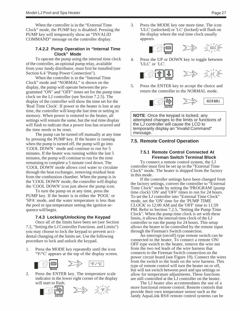
Model LJ Pool and Spa Heater Page 27
When the controller is in the “External TimeClock” mode, the PUMP key is disabled. Pressing thePUMP key will temporarily show an “INVALIDCOMMAND” message on the controller display.
7.4.2.2 Pump Operation in “Internal TimeClock” Mode
To operate the pump using the internal time clockof the controller, an optional pump relay, availablefrom your Jandy distributor, must first be installed (seeSection 6.4 "Pump Power Connection").
When the controller is in the “Internal TimeClock” mode and “NORMAL” is shown on thedisplay, the pump will operate between the pro-grammed "ON" and "OFF" times set for the pump timeclock on the LJ controller (see Section 7.2.5). Thedisplay of the controller will show the time set for the'Real Time Clock'. If power to the heater is lost at anytime, the controller will keep the last time or setting inmemory. When power is restored to the heater, allsettings will remain the same, but the real time displaywill flash to indicate that a power loss has ocurred andthe time needs to be reset.
The pump can be turned off manually at any timeby pressing the PUMP key. If the heater is runningwhen the pump is turned off, the pump will go into'COOL DOWN ' mode and continue to run for 5minutes. If the heater was running within the last 5minutes, the pump will continue to run for the timeremaining to complete a 5 minute cool down. The'COOL DOWN' mode allows cool water to circulatethrough the heat exchanger, removing residual heatfrom the combustion chamber. When the pump is inthe 'COOL DOWN' mode, the controller will displaythe 'COOL DOWN' icon just above the pump icon.
To turn the pump on at any time, press thePUMP key. If the heater is in either the 'POOL' or'SPA' mode, and the water temperature is less thanthe pool or spa temperature setting the ignition se-quence will begin.
7.4.3 Locking/Unlocking the KeypadOnce all of the limits have been set (see Section
7.2, "Setting the LJ Controller Functions and Limits")you may choose to lock the keypad to prevent acci-dental changing of the limits set. Use the followingprocedure to lock and unlock the keypad.
1. Press the MODE key repeatedly until the icon'°F/°C' appears at the top of the display screen.
2. Press the ENTER key. The temperature scaleindicator in the lower right corner of the displaywill start to flash.
3. Press the MODE key one more time. The icon'ULC' (unlocked) or 'LC' (locked) will flash onthe display where the real time clock usuallyappears.
4. Press the UP or DOWN key to toggle between'ULC' or 'LC'.
5. Press the ENTER key to accept the choice andreturn the controller to the NORMAL mode.
NOTE: Once the keypad is locked, anyattempted changes to the limits or functions ofthe LJ controller will cause the LCD totemporarily display an "Invalid Command"message.
7.5. Remote Control Operation
7.5.1 Remote Control Connected AtFireman Switch Terminal Block
To connect a remote control system, the LJcontroller must first be set up in the “External TimeClock” mode. The heater is shipped from the factoryin this mode.
If the controller settings have been changed fromthe factory settings, convert the controller to “ExternalTime Clock” mode by setting the 'PROGRAM' (pumptime clock) 'ON' and 'OFF' times to run for 24 hours.To set the LJ controller into “External Time Clock”mode, set the 'ON' time for the 'PUMP TIMECLOCK' to 12:00 AM and the 'OFF' time to 11:59PM. Refer to Section 7.2.5, "Setting the Pump TimeClock". When the pump time clock is set with theselimits, it allows the internal time clock of the LJcontroller to run the pump for 24 hours. This setupallows the heater to be controlled by the remote inputthrough the Fireman's Switch connection.
An interrupt (on/off) type remote switch can beconnected to the heater. To connect a remote ON/OFF type switch to the heater, remove the wire nutfrom the two red leads of the wire harness thatconnects to the Fireman Switch connection on thepower circuit board (see Figure 19). Connect the wiresfrom the switch to the leads on the wire harness. Thistype of remote control will turn the heater on or off,but will not switch between pool and spa settings orallow for temperature adjustments. These functionsare still controlled at the LJ controller on the heater.
The LJ heater also accommodates the use of amore functional remote control. Remote controls thatprovide their own temperature sensor such as theJandy AquaLink RS® remote control systems can be
°F / °C
NORMAL
°F
ULC
LC

Page 28
wired to the Fireman Switch connection. The LJcontroller must first be set up to recognize the remotemode. The set up consists of setting the 'PROGRAM'(pump time clock) 'ON' and 'OFF' times to run for 24hours, setting the controller function to 'SPA' andsetting the spa temperature to 104°F (40°C).
To set the LJ controller for remote control use,follow the instructions at the beginning of this sectionsetting the controller into the "External Time Clock"mode.
To operate the heater by the remote unit, use theSELECT key on the LJ controller keyboard to setthe heater to the 'SPA' mode.
Then follow the instructions in Section 7.2.3,"Setting the Pool and Spa Temperatures", to set thespa temperature limit to 104°F (40°C). This will allowthe remote system's temperature settings to control thewater temperature to a maximum of 104°F (40°C).
The LJ controller now acts as a "slave" controllerand heater functions are controlled by the remotecontrol system.
To restore control of the heater functions to theLJ controller, disconnect the remote system from theFireman Switch, reprogram the pump time clock todesired settings and reset the 'SPA' temperature to thedesired setting.
7.5.2 Remote Control Connected At TheHeater's Control Panel
The LJ heater control also provides the option ofusing a remote switch to change the mode of theheater. This remote will allow the user to change themode of the heater between 'POOL', 'SPA' and 'OFF'.A more functional remote may be installed as stated inthe previous section.
A special Jandy wire harness is needed to installthe owner provided remote mode switch. Contact yourlocal Jandy distributor to order the wire harness kit(Part Number R0398400). The wire harness kitincludes detailed instructions for the installation of thewire harness and remote switch.
7.6 Water Pressure Switch Adjustment
CAUTIONThe water pressure switch should be adjustedto turn the heater off when the pump is off.Setting the switch to close at too low of a flowcan damage the appliance. Adjust the switch toturn the heater off, not on.
ATTENTIONLe manocontact de pression d’eau doit êtreréglé de façon à ce que l’appareil cesse defonctionner si la pompe s’arrête. Si lemanocontact est réglé pour se fermer lorsquele débit d’eau est trop faible, l’appareil risque des’endommager. Réglez le manocontact pourqu’il arrête l’appareil, et non pour qu’il le metteen marche.
The pressure switch is preset at the factory foractivation at 2 psi (14 kPa). Adjust the pressure switchonly if any part of the filter system piping is 3 feet(0.91 m) or more above the top of the heater jacket.
Do not adjust the pressure switch if the heater isinstalled more than 15 feet (4.57 m) above or 6 feet(1.83 m) below the pool surface. Consult your localJandy representative for recommendations.
On some installations, the piping from the heaterto the pool is very short. The back pressure could betoo low to trigger the pressure switch. If this happens,it may be necessary to install a directional fitting orelbows where the return line enters the pool. This willincrease back pressure enough for the heater tooperate properly.
Make sure the pool filter is clean before makingany pressure switch adjustment: A dirty filter willrestrict the water flow and the pressure switch cannotbe adjusted properly. To adjust the pressure switch:
1. Turn the pump 'OFF' by pressing the PUMP keyso that the display shows that the pump is 'OFF'.If the heater was running it should go off immedi-ately and the pump will run in the 'COOLDOWN' mode for 5 minutes. If the heater hasbeen running within the last 5 minutes, the pumpwill continue to run for the remainder of the 5minute cool down period (see Figure 20).
2. Set the pool temperature control to the maximumsetting. Repeatedly depress the MODE key untilthe indicator at the top of the display shows'POOL SET'. Press the ENTER key. Then usethe UP key to set the temperature to 104°F(40°C). Press the ENTER key again.
CONTROLLER
FLAME SENSOR
GAS VALVE
SAFETY CIRCUIT
FIREMANSWITCH
PUMP
BLOWER
POWER INSELECT
PLUG
IGNITER
POWERIN
R
POWERIN
ON
OFF
R
Figure 19. ON/OFF Type remote switch
Figure 20. LJ controller display

Model LJ Pool and Spa Heater Page 29
3. Turn filter pump on by depressing the PUMPkey. If a two-speed pump is used, make sure itis at high speed.
NOTE: Heater should not be allowed to fire onlow speed.
4. Set the controller to 'POOL' by repeatedlydepressing the SELECT key until the displayshows that the heater is set to 'POOL'. Theheater should start.
5. Pry out the rubber dust plug on the top of thepressure switch.
6. Use a 7/32 inch (5.55 mm) Allen wrench to turnthe adjustment screw very slowly clockwiseuntil the heater goes off (see Figure 21).
9. Return the pool temperature control to the desiredtemperature. Repeatedly depress the MODE keyuntil the indicator at the top of the display shows'POOL SET'. Press the ENTER key. Then usethe UP and DOWN keys to set the heater to thedesired temperature. Press the ENTER key again.
7.7 Temperature RiseA temperature rise test confirms proper water
flow through the heater. The temperature rise is thedifference between the temperature of the pool or spawater before and after heating, as measured in theheader. Perform the following temperature rise testwhen the installation is complete:
1. Make sure the pool filter is clean.
2. Set the controller to 'OFF' by repeatedly depress-ing the SELECT key until the display shows thatthe heater is 'OFF'.
3. If the filter pump is on, turn it off by pressing thePUMP key and allow up to five minutes for thepump to shut down.
4. Turn off the power supply to the heater at thecircuit breaker panel.
5. Remove the drain plug located on the inlet/outletheader of the heater and replace it with a Pete'splug (see Figure 15).
6. Insert a pocket thermometer (see Figure 15)through the Pete's plug into the header.
7. Turn the circuit breaker on to supply the heaterwith power.
8. Turn the filter pump on and wait 3 minutes. Theheater remains off. This allows water from thepool to reach the heater.
9. Record the temperature indicated by the ther-mometer (cold water).
10. Set the pool temperature control to the maximumsetting. Repeatedly depress the MODE key untilthe indicator at the top of the display shows'POOL SET'. Press the ENTER key. Then usethe UP key to set the temperature to 104°F(40°C). Press the ENTER key again.
11. Set the controller to 'POOL' by repeatedlydepressing the SELECT key until the displayshows that the heater is set to 'POOL'. Theheater should start.
12. Allow the heater to run for about 3 minutes.Record the new temperature reading (heatedwater).
Figure 21. Pressure Switch Adjustment
7. Slowly turn the pressure switch adjustmentscrew counterclockwise one-quarter turn. Theheater should come back on.
8. Check the adjustment. Press the SELECT keyto turn the heater 'OFF'. Turn off the power tothe heater at the breaker. Unplug the pumprelay from the power circuit board. Restorepower to the heater. Press the SELECT key toset the heater to 'POOL'. The heater mustnot come on. If the heater does start the firingsequence, immediately press the SELECT keyto turn the heater off; disconnect power to theheater; plug the pump relay into the powercircuit board and restore the power to theheater. Then repeat Steps 6 and 7. Check theadjustment again. When the adjustment hasbeen checked and verified, press the SELECTkey to turn the heater off; disconnect power tothe heater; plug the pump relay into the powercircuit board and restore the power to theheater.

Page 30
13. Subtract the first temperature reading (coldwater) from the second temperature reading(heated water). The difference between the tworeadings is the temperature rise. The tempera-ture rise should be within the range shown inTable 7.
b. Turn the filter pump off by pressing thePUMP key and allow up to five minutes forthe pump to shut down.
c. Turn off the power to the filter pump at thecircuit breaker.
d. Remove thermometer and Pete's plug.
e. Replace the drain plug.
f. Turn on the power to the filter pump at thecircuit breaker.
g. Return the pool temperature control to thedesired temperature. Repeatedly depress theMODE key until the indicator at the top ofthe display shows 'POOL SET'. Press theENTER key. Then use the UP and DOWNkeys to set the heater to the desiredtemperature. Press the ENTER key again.
7.8 Adjusting the Manual Bypass ValveAfter the manual bypass valve is installed, use
the following procedures to adjust the bypass valve:
1. Make sure the pool filter is clean.
2. If the filter pump is on, turn it off by pressing thePUMP key and allow up to five minutes for thepump to shut down.
3. Turn off the power supply to the heater at thecircuit breaker panel.
4. Remove the drain plug located on the inlet/outletheader of the heater and replace it with a Pete'splug (see Figure 15).
5. Insert a pocket thermometer (see Figure 15)through the Pete's plug into the header.
6. Turn the circuit breaker on to supply the heaterwith power.
7. Close manual bypass valve.
8. Set the controller to 'OFF' by repeatedly depress-ing the SELECT key until the display shows thatthe heater is 'OFF'.
9. Repeat steps 8 through 13 of the temperaturerise test (see Section 7.7).
10. If the temperature rise is below the minimumstated in Table 7, open the manual bypass valveuntil temperature rise climbs between the min.
14. If the temperature rise is below the minimumrange indicated, two possibilities arise:
a. The supply gas volume is too low. Checkmanifold gas pressure and make necessarycorrections before before proceeding.
b. The system's water flow exceeds 125 GPM(475 LPM), and requires a manual bypassvalve for proper operation. Install a manualbypass (see Figure 7) and proceedto Section 7.8.
15. If the temperature rise is above the maximum,there is not enough water flowing through theheater. Check for clogging in the water filter orrestriction in the water pipes.
CAUTIONOperating the heater with the temperature riseabove maximum or below the minimum candamage the heater and may void the warranty.
ATTENTIONOpérer le chauffe-piscine au-dessus du niveaude température maximale ou sous le niveau detempérature minimale recommandée, peutendommager le chauffe-piscine et ainsi annulerla garantie.
16. If the temperature rise is within the correctrange, complete the procedure as follows:
a. Set the controller to 'OFF' by repeatedlydepressing the SELECT key until thedisplay shows that the heater is 'OFF'.
Minimum Minimum Maximum
Size GPM (LPM) °F (°C) °F (°C)
125 20 (76) 27 (15) 36 (20)175 20 (76) 33 (19) 42 (24)250 25 (95) 33 (19) 42 (24)325 30 (114) 28 (16) 38 (21)400 30 (114) 30 (17) 39 (22)
Table 7. Temperature Rise and Minimum Flow Rates
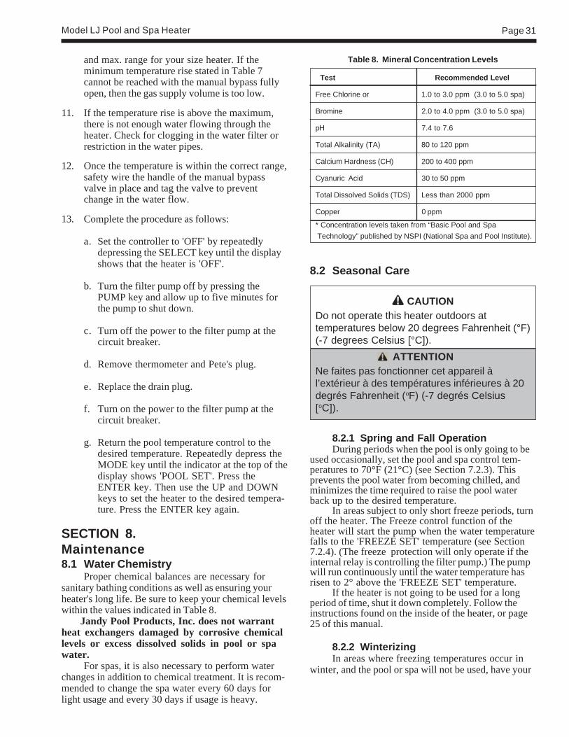
Model LJ Pool and Spa Heater Page 31
and max. range for your size heater. If theminimum temperature rise stated in Table 7cannot be reached with the manual bypass fullyopen, then the gas supply volume is too low.
11. If the temperature rise is above the maximum,there is not enough water flowing through theheater. Check for clogging in the water filter orrestriction in the water pipes.
12. Once the temperature is within the correct range,safety wire the handle of the manual bypassvalve in place and tag the valve to preventchange in the water flow.
13. Complete the procedure as follows:
a. Set the controller to 'OFF' by repeatedlydepressing the SELECT key until the displayshows that the heater is 'OFF'.
b. Turn the filter pump off by pressing thePUMP key and allow up to five minutes forthe pump to shut down.
c. Turn off the power to the filter pump at thecircuit breaker.
d. Remove thermometer and Pete's plug.
e. Replace the drain plug.
f. Turn on the power to the filter pump at thecircuit breaker.
g. Return the pool temperature control to thedesired temperature. Repeatedly depress theMODE key until the indicator at the top of thedisplay shows 'POOL SET'. Press theENTER key. Then use the UP and DOWNkeys to set the heater to the desired tempera-ture. Press the ENTER key again.
SECTION 8.Maintenance8.1 Water Chemistry
Proper chemical balances are necessary forsanitary bathing conditions as well as ensuring yourheater's long life. Be sure to keep your chemical levelswithin the values indicated in Table 8. Jandy Pool Products, Inc. does not warrantheat exchangers damaged by corrosive chemicallevels or excess dissolved solids in pool or spawater.
For spas, it is also necessary to perform waterchanges in addition to chemical treatment. It is recom-mended to change the spa water every 60 days forlight usage and every 30 days if usage is heavy.
8.2 Seasonal Care
CAUTIONDo not operate this heater outdoors attemperatures below 20 degrees Fahrenheit (°F)(-7 degrees Celsius [°C]).
ATTENTIONNe faites pas fonctionner cet appareil àl’extérieur à des températures inférieures à 20degrés Fahrenheit (oF) (-7 degrés Celsius[oC]).
8.2.1 Spring and Fall OperationDuring periods when the pool is only going to be
used occasionally, set the pool and spa control tem-peratures to 70°F (21°C) (see Section 7.2.3). Thisprevents the pool water from becoming chilled, andminimizes the time required to raise the pool waterback up to the desired temperature.
In areas subject to only short freeze periods, turnoff the heater. The Freeze control function of theheater will start the pump when the water temperaturefalls to the 'FREEZE SET' temperature (see Section7.2.4). (The freeze protection will only operate if theinternal relay is controlling the filter pump.) The pumpwill run continuously until the water temperature hasrisen to 2° above the 'FREEZE SET' temperature.
If the heater is not going to be used for a longperiod of time, shut it down completely. Follow theinstructions found on the inside of the heater, or page25 of this manual.
8.2.2 WinterizingIn areas where freezing temperatures occur in
winter, and the pool or spa will not be used, have your
Table 8. Mineral Concentration Levels
Test Recommended Level
Free Chlorine or 1.0 to 3.0 ppm (3.0 to 5.0 spa)
Bromine 2.0 to 4.0 ppm (3.0 to 5.0 spa)
pH 7.4 to 7.6
Total Alkalinity (TA) 80 to 120 ppm
Calcium Hardness (CH) 200 to 400 ppm
Cyanuric Acid 30 to 50 ppm
Total Dissolved Solids (TDS) Less than 2000 ppm
Copper 0 ppm
* Concentration levels taken from “Basic Pool and Spa Technology” published by NSPI (National Spa and Pool Institute).

Page 32
service technician perform the following steps:
1. Turn off the main gas supply valve to the heater,outside the heater jacket.
2. Remove heater door.
3. Shut down the heater following the shutdowninstructions found on the inside of the heater.
4. Remove the drain plug from the return header(see Figure 22), loosen the drain plug from theinlet/outlet header, and completely drain theheater before the first frost.
5. After all water has drained from the heater,remove the drain plug from the inlet/outlet side.Check for mineral buildup in the openings.
6. Use compressed air to blow out any standingwater remaining in the heat exchanger.
7. Grease the threads on the drain plugs andreinstall plugs, but do not tighten.
8. Disconnect the pressure switch from the siphontube (copper tubing) (see Figure 23).
8.2.3 Spring Start-upTo restart the heater in the Spring, have a
professional service technician reassemble the heateras follows:
1. Attach the copper tubing to the pressure switch(see Figure 23).
2. Tighten the drain plugs.
3. Make sure that power is supplied to the heatercontroller and the pump. Turn on the filter pumpby pressing the PUMP key and circulate waterthrough the heater for 5 minutes. Check for leaks
while circulating.
4. Turn on the main gas supply valve to the heater,outside the heater jacket.
5. Turn on the heater following the lighting instruc-tions found on the inside of the heater, or page 25of this manual.
8.3 Inspection and ServiceJandy Pool Products, Inc. designs and constructs
the Lite2 heater to provide long performance life wheninstalled and operated properly under normal condi-tions. Periodic inspections, especially at Spring start-up, are important to keep your heater running safelyand efficiently through the years. Improper mainte-nance can result in conditions where nausea orasphyxiation from carbon monoxide or flue gases couldcause severe injury, property damage or death.
WARNINGImproper installation or maintenance can causenausea or asphyxiation from carbon monoxidein flue gases which could result in severe injury,or death.
Figure 22. Heater drain locations
Figure 23. Pressure switch copper tubing

Model LJ Pool and Spa Heater Page 33
AVERTISSEMENTUne installation ou un entretien inadéquat peutcauser la nausée ou l’asphyxie en raison dumonoxyde de carbone présent dans les gaz decombustion et même entraîner des blessuresgraves ou la mort.
8.3.1 Owner InspectionJandy Pool Products, Inc. recommends that you
inspect the heater on a continual basis and especiallyafter abnormal weather conditions. The following basicguidelines are suggested for your inspection:
1. Keep the top and surrounding area of the heaterclear of all debris.
2. Keep the area around and beneath the heaterclean and free of all combustible materials suchas paper, leaves, etc.
3. Do not store or use gasoline or other flammablevapors, liquids or chemicals in the vicinity of thisor any other appliance.
Ne pas entreposer ni utiliser d'essence ni d'autresvapeurs ou liquides inflammables à proximité decet appareil ou de tout autre appareil.
4. Do not use the heater if any part has been underwater. Immediately call a qualified professionaltechnician to inspect the heater and replace anypart of the control system which has beensubmerged.
N'utilisez pas cet appareil s'il a été plongé dansl'eau, même partiellement. Faites inspecterl'appareil par un technicien qualifié et remplaceztoute partie du système de contrôle et toutecommande qui ont été plongés dans l'eau.
5. If the heater is equipped with a pressure reliefvalve, check for corrosion in and around thevalve. Twice a year, with the filter pump on, liftthe release lever on the top of the valve to makesure that water runs freely through it. If corro-sion is found, replace the pressure relief valve.When replacing the valve, be sure that the pumpis off. Install the valve so that the discharge isdirected away from any area that may bedamaged by water.
6. Be sure all combustion air and ventilation open-ings are not blocked. Check for spider webs andother debris inside the heater, in the vents on allsides of the heater jacket and in the exhaustoutlet– especially after a long period of nonuse.
8.3.2 Professional InspectionInspections performed at least once a year by a
qualified technician are required to maintain yourheater's safe and efficient operation. The followingbasic safety checks must be performed.
1. Inspect the venting system for blockage, leakage,and corrosion.
2. Check for spider webs in or other obstructions inthe main burner orifices – especially at Springstart-up. Clean with wire brush if necessary.
3. Check for loose or broken wires and terminalconnections.
4. Inspect the electrical controls, specifically thefollowing:
a. High limit controls.b. Water pressure switch.c. Temperature control.d. Ignition control.e. Automatic gas valve.f. Fusible link.g. Igniter fuses.h. Control circuit fuse (Power Board).i. Power distribution board.
5. Inspect the external surfaces of the heat ex-changer tubes for black carbon soot buildup byplacing a mirror between and under the burnerswhen the heater is firing. Remove any soot thathas collected on the tubes, and correct the cause.
NOTE: After installation and first start-up,check the heat exchanger for black carbon sootbuildup after the following periods of operation:24 hours, 7 days, 30 days, 90 days, and onceevery 6 months thereafter.
6. If the heater is equipped with a pressure reliefvalve, check for corrosion in and around thevalve. With the filter pump on, lift the releaselever on the top of the valve to make sure thatwater runs freely through it. If corrosion is found,replace the pressure relief valve. When replacingthe valve, be sure that the pump is off. Install thevalve so that the discharge is directed away fromany area that may be damaged by water.
7. Verify pressure switch operation. Press theSELECT key to turn the heater 'OFF'. Turn offthe power to the heater at the breaker. Unplugthe pump relay from the power circuit board.Restore power to the heater. Press the SELECTkey to set the heater to 'POOL'. The heatermust not come on. If the heater does start thefiring sequence, immediately press the SELECT

Page 34
key to turn the heater off, disconnect power tothe heater, plug the pump relay into the powercircuit board and restore the power to the heater.Refer to Section 7.6 "Adjusting the PressureSwitch" for procedures on adjusting the pressureswitch. When the adjustment has been checkedand verified, press the SELECT key to turn theheater off, disconnect power to the heater, plugthe pump relay into the power circuit board andrestore the power to the heater.
8. Conduct a normal operating cycle and observethat the sequence proceeds as intended.
CAUTIONFor your safety, when starting the heater, keepyour head and face away from the lower fireboxopening to prevent any risk of personal injury.
ATTENTIONPour votre sécurité personnelle, lorsque vousmettez l’appareil en marche, tenez votre tête etvotre visage loin du brûleur pour éviter toutrisque de blessure.
9. Make a visual check of the main burner flame.The flame can be seen in a mirror arrangementheld beneath the burners. The flame should be:
a. Blue in color.b. 1 to 4 inches (25mm to 102mm) above
burner surface (see Figure 24).
NOTE: Keep this manual in a safe place forfuture reference by you and your professionaltechnician when inspecting and servicing theheater.
SECTION 9.Troubleshooting
9.1 General Heater TroubleshootingThe table on the following page lists some of the
more common problems, causes and solutions encoun-tered when running the heater. Most problems occurwhen the heater is being started for the first time afterinstallation or at Spring start-up. Careful installationand maintenance will help ensure years of trouble freeuse from your Lite2 pool heater.
9.2 LJ Controller Service Codes9.2.1 Explanation of Service CodesThe LJ controller monitors several functions of
the heater. In the event of a malfunction, the controllerwill display a service code where the inlet tempera-ture is usually displayed and a service icon in themiddle of the display. See Figure 25 for appearanceand location of typical service code display.
Figure 24. Main Burner Flame
10. Perform a temperature rise test in accordancewith Section 7.7.
11. Return the pool temperature control to thedesired temperature. Repeatedly depress theMODE key until the indicator at the top of thedisplay shows 'POOL SET'. Then use the UPand DOWN keys to set the heater to the desiredtemperature.
Figure 25. Typical Service Code Display
The service codes are listed on the followingpages.
Only three of these service codes are reconcil-able without the services of a qualified technician. Thefirst is the case where the heater does not start afterthe first three attempts, FL2. This may occur after aprolonged period of nonuse of the heater, especially atSpring start-up. However, the repeated appearance ofthis error requires the service of a qualified technician.
The second case is that of a temporary brown-out condition, FL5. If the brown-out is regional, thenthe controller will automatically reset when full poweris restored by the electric company. However, if thebrown-out is due to a low voltage supply problem onlyon the heater circuit, then immediately shut off theelectrical supply to the heater and call a certifiedelectrician.
The last case is the filter is dirty condition, FL0.

Model LJ Pool and Spa Heater Page 35
Troubleshooting Table# Symptom Cause Remedy
1. Pump not A.No power A.Check circuit breakers and power source.operating B. Pump defective B. Replace.
C. Incorrectly wired C. Recheck wiring including relay if using LJ controller internalclock.
D. Pump relay defective D. Replace pump relay.E. Current time not within E. Set time clock and current time.
time clock settingsF. Controller defective F. Replace controller.
2. Flame roll-out A.Blocked flue A.Remove blockage.on start-up B. Igniter out of position (delayed ignition) B. Correct igniter position.
C. Blocked heat exchanger C. Clean and correct as necessary.D. Refractory blanket out of place D. Correct or replace blanket as necessary.E. Altered draft hood E. Install factory-provided draft hood.F. Downdraft conditions F. Install draft hood.
3. Spillage at A.Cold chimney A.Allow heater to operate 5 minutes to create draft action.draft hood B. Vent pipe pitches down to chimney B. Reinstall vent pipe to pitch up from heater to chimney.
C. Blocked chimney C. Remove blockage.D. Draft hood altered D. Install factory-provided draft hood.E. Prefabricated chimney with incorrect cap E. Install a Nationally Recognized Testing Lab (NRTL) listed vent
cap.
4. Flame has A.Low primary air A.Correct manifold pressure according to rating plate. Correctlazy yellow tip orifice size if necessary (see parts list). Clean burner ports if
dirty.
5. Not enough heat A.Inadequate gas supply A.Gas meter too small. Gas line from meter to heater too small.B. Low manifold gas pressure B. Gas pressure on heater manifold should be adjusted to
4.0"W.C. for natural gas, 9.0"W.C. for propane.C. Heater size inadequate C. Replace with heater of higher input.
6. Heater pounding A.Water flow through heater too low A.Check temperature rise between inlet and outlet heateror knocking piping. See Section 7.7 for recommended range of
temperature rise. If temperature rise is above the maximumrecommended, increase pipe size or pump capacity orlocate obstruction. Check for closed valve in system.
7. Heater condensing A.Low water temperature A.Flue product moisture will condense at the start-up until theheater water temperature reaches the normal operatingconditions.
B. Heater plumbed backwards B. Correct plumbing.
8. Igniter lights but A.Gas valve not at “on” position A.Turn knob to “on” position.main burners B. Air in gas line B. Cycle ignition sequence until air is out of the gas line.will not come on C. Gas valve failed C. Replace gas valve.
Service code FL0, "open switch in the safetycircuit", will reset after the open switch has been resetor replaced. The display will show the normal operat-ing icons.
NOTE: If the pump is turned off while theheater is running, service code FL0 will bedisplayed because the water pressure switchwill detect the drop in water pressure and openthe safety circuit. When the pump is restarted,the water pressure switch will close and theheater will resume normal operation.
Service code FL1, "temperature sensor shorted",will reset after the short has been repaired, or a newsensor installed. The display will show the normaloperating icons.
To clear the FL2 service code, turn off theheater by using the SELECT key to turn the heater tothe 'OFF' position and then turn it back to either'POOL' or 'SPA'. The heater will now go back to thenormal operating mode. If there is a call for heat theheater will attempt ignition again. If the ignition failsagain, contact a qualified technician to check theheater.
All other service codes will need the attention ofa qualified technician to resolve the problem.
9.2.2 Resetting LJ Controller ServiceCodes
The LJ controller will display service codes tohelp in identifying fault conditions that effect theoperation of the heater (see Section 9.2.1).
There are four service codes that will resetautomatically once the fault condition has been re-solved.

Page 36
FL 0(open switch in thesafety circuit)
FL 1(temperature sensor)
FL 2(failed ignition)
1. Pressure Switch OpenedA. Pump is not running.
B. Low pump/water pressure.
C. Air is in the water line.D. Pressure switch fault.
2. Hi Limit Switch TrippedA. Water temperature in heater
exceeds the internal limit.B. Limit switch fault.
3. Fusible Link OpenedA. Internal cabinet temperatures
exceed the fusible link limit.B. Fusible link fault.
1. Temperature Sensor ErrorA. Temperature sensor opened or
shorted.B. Failed sensor.
1. No IgnitionA. Low gas supply pressure.
B. Air in gas line.
C. No gas flowing.
D. Gas valve fault.
2. Ignition, but no Flame SensingCapabilitiesA. Flame sensor is not in the
flame.B. Flame sensor circuit is open.
C. Flame sensor rod is grounded.
D. Flame sensor circuit isshorted.
A. Turn pump on or check to see that external timeclock is synchronized with LJ controller timeclock.
B. Clean filter or clear blockage/check position ofvalves in plumbing system.
C. Check for air leaks in plumbing system.D. Adjust or replace pressure switch. Refer to
qualified personnel.
A. Identify and correct cause of overheating. Referto qualified personnel.
B. Identify and correct loose connections or replaceswitches. Refer to qualified personnel.
A. Identify and correct cause of overheating. Referto qualified personnel.
B. Identify and correct loose connections or replacefusible link. Refer to qualified personnel.
A. Check for loose connections and inspect sensorwires and routing.
B. Replace temperature sensor. Refer to qualifiedpersonnel.
A. Identify and repair incorrect supply pipe size orpipeline blockage. Refer to qualifiedpersonnel.
B. Shutdown heater and restart. If the heater doesnot ignite, refer to qualified personnel.
C. Be sure that the manual gas cock and theautomatic valve are in the "ON" position. Checkfor loose wire connections at gas valve.
D. Replace gas valve. Refer to qualifiedpersonnel.
A. Ensure that the flame sensor is aligned over theburner. Refer to qualified personnel.
B. Identify and correct loose connections. Refer toqualified personnel.
C. Ensure that flame sensor is installed properlyand is not in contact with burner or heater jacket.Refer to qualified personnel.
D. Inspect flame sensor rod, wiring and connectionsbetween sensor and power circuit board. Referto qualified personnel.
LITE2 LJ CONTROLLER HEATER SERVICE DIAGNOSTIC GUIDE
SERVICE CODE CAUSE REMEDY

Model LJ Pool and Spa Heater Page 37
SERVICE CODE CAUSE REMEDY
FL 2 (cont'd)(failed ignition)
FL 3(flame detected whenno flame shouldexist)
FL 4(igniter)
FL 5(brown-out)
FL 6(24V signal to gasvalve)
FL 7(remote operationcircuit)
E. Flame sensor circuitry is notwell grounded.
F. Low gas supply pressure.
G. Heater is wired incorrectly.
H. Failed sensor.
3. Rapidly Cycling PressureSwitchA. Air leak in water line or pump.B. Insufficient back-pressure to
heater.
1. Flame Sensor ErrorA. Flame exists prior to ignition
sequence.B. Failed controller.
1. Igniter FailureA. Igniter circuit is open.
B. Element has a fine crack in it.
C. Igniter fault.
1. Brown-out ConditionA. Incoming voltage is too low to
safely operate heater.
B. Heater supply voltage is 115Vbut power conversion plug isplugged in on 230V side.
1. Power Module FailureA. 24V signal is not being sent to
energize the gas valve.
1. Remote Operation CircuitA. Remote control switch circuit is
open. (Controller is not inremote control mode).
B. Remote control switch circuit isnot open.
E. Ensure that the green wire fromthe 6-pin connector to the power circuit board istightly attached to the ground screw with a starwasher.
F. Identify and repair incorrect supply pipe size orpipeline blockage. Refer to qualifiedpersonnel.
G. Ensure proper wiring. See wiring diagram inmanual or on door of heater for details. Refer toqualified personnel.
H. Replace flame sensor.
A. Locate and repair leak.B. Install restrictive fitting at pool/spa outlet. Refer
to qualified personnel.
A. Carefully inspect heater for signs of fire damage.Refer to qualified personnel.
B. Replace controller. Refer to qualifiedpersonnel.
A. Check fuses on igniter wires. Identify and correctloose connections or broken wires. Refer toqualified personnel.
B. Measure room temperature resistance andensure value is in the correct range. See manualfor details. Refer to qualified personnel.
C. Replace igniter. Refer to qualified personnel.
A. No Service Required. Heater will automaticallyreset itself once proper voltage is restored. Iferror persists, Refer to qualified personnel.
B. Reverse power conversion plug.
A. Replace power module board. Refer toqualified personnel.
A. Identify and correct loose connections. Refer toqualified personnel.
B. Replace power module board. Refer toqualified personnel.

Page 38
SECTION 10.Professional Maintenance andService
WARNINGSERVICING SAFETYSome of the servicing procedures for the Lite2model LJ pool heater are hazardous becausethey involve fuel gas, electricity, moving partsand procedures which require testing ortemporary bypass of safety controls. For thisreason, the heater must be serviced only by aqualified professional service technician.
IMPROPER SERVICE HAZARDThe Lite2 model LJ pool heater incorporatesunique design features. Incorrect service of thisheater can result in personal injury or damageto property. To avoid such hazards, the heatermust be serviced only by a qualifiedprofessional service technician.
AVERTISSEMENTPRÉCAUTIONS LORS DES RÉPARATIONSET DE L’ENTRETIENCertaines procédures d’entretien et deréparation des appareils de chauffage à LJprésentent des dangers, car elles mettent enjeu des gaz combustibles, des composantsélectriques, des pièces mobiles et desprocédures qui nécessitent des mises à l’essaiou la dérivation temporaire des commandes desécurité. Pour cette raison, l’appareil dechauffage doit être entretenu et réparéuniquement par un technicien professionnelqualifié.
DANGERS D’UN ENTRETIEN INADÉQUATLes appareils de chauffage à LJ comportentdes caractéristiques techniques uniques. Uneréparation ou un entretien inadéquat peutentraîner des blessures corporelles ou desdommages à la propriété. Pour cette raison,l’appareil de chauffage doit être entretenu etréparé uniquement par un technicienprofessionnel qualifié.
10.1 General InformationA qualified professional technician must service
the Lite2 model LJ pool heater using Jandy PoolProducts, Inc. service procedures. Before calling forservice, however, the owner should check for obviousproblems. The other components in the pool system,including pump, filters and strainers, water valves, gassupply, electrical power and time clocks, have aneffect on heater operation.
Confirm that the LJ heater control is set to'POOL' or 'SPA' and that the corresponding tempera-ture limit is set high enough to make the heater oper-ate. Make sure the pump is operating, that the filter isclean and strainers are not clogged, that there are nomis-positioned water valves, that the gas or electricpower supplies are not shut off and that time clocksare properly adjusted. Also be sure that there is noblockage of the vent or louvers which supply combus-tion air to the burners.
10.2 Natural-Draft Combustion SystemThe Lite2 model LJ pool heater has an atmo-
spheric combustion system. This system is illustrated inFigure 26.
As the heated exhaust gases rise out of thecombustion chamber, flow is created through thesystem and fresh combustion air is drawn into theheater through the louvers cut into the front and sidesof the heater. Gas is forced through an orifice into the
Service code FL3, "flame detected when noflame should exist", will reset after the problem hasbeen resolved.
Service code FL5, "brown-out condition exists",will also reset after the condition has been resolved.However, the reset may take up to 3 minutes. The LJcontroller checks the power supply voltage every 3minutes. If the supply voltage drops below 85% of thenominal supply voltage, the display will show the FL5service code and the heater will not start the ignitionsequence. The controller will check the supply voltageagain 3 minutes later. If the low voltage condition stillexists the FL5 service code will remain. If the actualsupply voltage is above 85% of the nominal supplyvoltage, the service code will clear automatically fromthe display and the heater will resume normal opera-tion. If the heater was in either 'POOL' or 'SPA' modewhen the brown-out condition was detected, it willremain in that mode when the condition is resolved. Ifthe water temperature is less than the thermostatsetting, the ignition sequence will start automaticallyand the heater will operate normally.
Once any other service code has been displayed,it will need to be reset after the fault condition hasbeen resolved. Once the problem has been identifiedand repaired, press the SELECT keyrepeatedly to turn the heater off . Thenpress the SELECT key again to set the controller toeither 'POOL' or 'SPA'. The controller should send theheater through the ignition sequence and the heaterwill operate normally.

Model LJ Pool and Spa Heater Page 39
open end of a burner. When the gas flows into theburner, a “negative” pressure is created at the openingof the burner. This negative pressure pulls air into theburner with the gas and mixes the two together. Asthe gas/air mixture flow through the burner ports it isignited in the combustion chamber. Hot combustionproducts then raise through a highly efficient heatexchanger. Combustion products then enter a fluecollector and are directed to the outdoors through thegrate top of the heater or a vent pipe and cap.
10.3 Heater Components and Their Operation
1. Gas valve / Regulator - The gas valve controlsgas flow into the manifold. It provides flow onlywhen the temperature controls require heat andonly if all safety controls enable operation. It isalso a positive pressure regulator. It regulatesthe gas pressure in the manifold to specificationsaddressed earlier in this manual. This is neces-sary for proper operation of the burner system.
2. LJ Temperature Control/Ignition ControlCombination System-a. Temperature Control-The Jandy LJcontroller is an electronic control which senseswater temperature by means of a thermistor andcontrols heater operation to bring the water to thetemperature selected. It has an option for twoseparate thermostat settings which are typically
used to set pool and spa temperatures. A push-button selector key is used to switch betweensettings.b. Ignition Control - The ignition control isintegrated with the temperature control. Itprovides energy for ignition of the air/gas mix-ture, monitors the flame and controls the gasvalve. When the temperature control requiresheat, the ignition control provides a pre-purge ofthe combustion chamber. Then it applies electri-cal power to a “hot surface” igniter. When theigniter is hot enough, the ignition control opensthe gas valve. It has sophisticated means tosense ignition and flame condition so that un-burned gas will not escape. After the burner isshut off, the ignition control continues operationto provide a post-purge period.
3. Igniter - The hot surface igniter is a ceramiccomposite element which becomes very hotwhen electrical power is applied to it. The hotsurface igniter directly ignites the air/gas mixturein the combustion chamber.
4. Flame Sensor - The flame sensor is the elec-trode through which the ignition control detects“rectification” of current passed through theflame. Inadequate rectification indicates anunsatisfactory flame condition. The ignitioncontrol responds to the flame signal provided bythe flame sensor.
FLUE COLLECTOR
HEAT EXCHANGER
COMBUSTION CHAMBER
BURNER
BURNER TRAY SHELF
VENT TOP
EXHAUST
AIR
FLOW
Figure 26. Atmospheric Combustion System

Page 40
1110
1
3
2
4
9
78
6
5
CIRCUIT TEST POINTS
POWER DISTRIBUTION BOARD TEST POINTS
Figure 27. Power and Control Circuit Test Points

Model LJ Pool and Spa Heater Page 41
5. Limit Switches - Two limit switches preventexcessive water temperature - one within theheat exchanger and one for water leaving theheater. If either senses excessive temperature,burner operation is interrupted.
6. Water Pressure Switch - This control senseswhether or not water is available to the heater bymeasuring back pressure inside of the heatexchanger. If the pool water pump fails or thewater filter is blocked, the pressure switchprevents operation of the burner.
7. Fusible Link - This is a single-use switch whichdetects abnormal temperature in the componentvestibule. It is a fusible link which is held to theinner panel just above the burner tray by a sheetmetal bracket. Excessive temperature in thecomponent compartment, possibly due to ablocked flue or flame roll-out, will cause the linkto fail. This opens the safety circuit which shutsoff the gas valve and shuts the heater down.
10.4 Electrical TroubleshootingThis section describes procedures for checking
the electrical power and control components of theheater one at a time and in the order they appear in thecontrol circuit.
Note: Pump must be running during thetroubleshooting procedure.
These procedures require a Volt-Ohm meterwith a minimum 0-250 VAC voltage range, and 0-1000Ohm resistance range. Figure 27 shows the power andcontrol circuits, and where to take measurements.Location numbers and letters in circles have beenadded, and will be referenced in the following sections.
As stated at the beginning of this manual, someof these procedures are hazardous. Only a qualifiedservice technician should service the heater.
10.4.1 Electrical Power SupplyThe electrical components of the Lite2 pool
heater are designed to operate with supply voltageranging from 98V to 126V at 60 Hz if connected to anominal 115 volt power supply or 196V to 253V at 60Hz if connected to a nominal 230 volt power supply.Measure supply voltage at the “hot” and “neutral”screw terminals in the heater electrical junction box(identified as points A and B on the wiring diagram). Ifno voltage is present, correct this external powersupply problem to the heater. Circuit breakers, timeclock settings or similar devices may be the problem.Voltage outside of the above ranges may be due topoor wiring, poor connections, other loads such as airconditioning compressors or to an electric utilitycompany problem. Arrange for correction of thevoltage as appropriate.
10.4.2 ControllerThe controller must be operational in order to
check the control circuits of the heater. If the red LEDon the power distribution board is on but the controllerdoes not show a display, then it is defective. Replacethe controller. If the LED is not on, then check thecontrol circuits as outlined in the following sections.
10.4.3 Control Circuit TroubleshootingThe heater controls and sensors are powered by
three major circuits on a power distribution board (PCboard). 115 VAC or 230VAC is brought to the powerdistribution board by the heater supply voltage. Thevoltage is then transmitted through the board and thepower conversion plug to the igniter and to a trans-former. When 115V is supplied to the heater, thepower conversion plug passes the signal unchanged tothe igniter and configures the input to the transformerfor 115V. When 230V is supplied to the heater, thepower conversion plug modifies the voltage to 115Vbefore sending it on to the igniter and configures theinput to the transformer for 230V. It is important to besure that the correct side of the power conversion plugis plugged into the power distribution board. Thetransformer converts the 115 volt AC or 230 volt ACsupply into two separate outputs, 24 volts AC and 12volts AC. These voltages are supplied back to thepower distribution board where the 24 volt signal isused to power the fireman switch, safety circuit andgas valve, while the 12 volt signal is used to power thekeypad controller. Troubleshooting is done by probingfor voltage at various points on the power distributionboard, and heater components to determine whichcomponent is preventing operation. Check points areindicated on Figure 27. The recommended proceduresteps through each circuit in a sequential way, andeach section assumes that components from allprevious sections have been tested and are opera-tional. However, verifying voltage at any of thenumbered points in that circuit confirms that all priorcomponents of the circuit are operational. Experiencedtechnicians may be able to shorten the process bygoing directly to one of the intermediate major testpoints. For example, if 24 volts is measured at testpoint 8, then all components in the circuit prior to testpoint 8 (fireman switch and entire safety circuit) areoperational.
10.4.3.1 TransformerTo check the 24 volt transformer output, attach
the black lead of the voltmeter to the transformerconnector where the blue wire enters near the centerof the connector (test point 1 on Figure 27). You willneed to push the voltmeter lead into the back of theconnector along side of the wire pin. Touch the freelead of the meter to the transformer connector wherethe second blue wire is attached at the end of theconnector (test point 2). The meter should show 20-28

Page 42
volts. If there is no voltage, replace the transformer.To test the 12 volt transformer output, leave the blacklead of the meter at test point 1 and touch the freelead of the meter to the transformer connector wherethe white wire is attached (test point 3). The metershould show 10-14 volts. If there is no voltage, replacethe transformer.
10.4.3.2 FuseLeaving the black voltmeter lead in place at test
point 1, touch the free lead to the end of the fuse (testpoint 4). The meter should read 20-28 volts. If there isno voltage, the fuse has failed. Inspect the rest of thewiring, especially the safety circuit, to be sure thatthere is no “short” such as contact of a terminal withthe heater chassis or another terminal which may havecaused the fuse to fail. Correct any such condition andreplace the fuse.
10.4.3.3 Fireman Switch and ExternalInterlocks
Check the voltage going to the external device.Move the black voltmeter lead to test point 2. (Thislead can be left in place for most of the testing.)Touch the free lead of the meter to the fireman switchconnector where the red wire is attached at the lowerend of the connector (test point 5). The meter shouldread 20-28 volts. If there is no voltage, there may be abad connection on the power distribution board and theboard may need to be replaced. If voltage is detectedat test point 5, move the free lead of the meter to thefireman switch connector where the other red wire isattached at the upper end of the connector (test point6). The meter should read 20-28 volts. If there is novoltage, the time clock switch or other externalinterlock may be mis-adjusted, mis-connected ordefective. Correct this external problem.
10.4.3.4 Fusible LinkCheck the voltage going to the safety circuit.
Leave the black voltmeter lead in place at test point 2.Touch the free lead of the meter to the safety circuitof the six pin connector where the red wire is attachedat the lower left corner of the connector (test point 7).The meter should read 20-28 volts. If there is novoltage, there may be a bad connection on the powerdistribution board and the board may need to bereplaced. If voltage is detected at test point 7, movethe free lead of the meter to the terminal of the fusiblelink where the white wire is connected (test point C).
If no voltage is detected at test point C, thefusible link has failed. This indicates higher thannormal temperatures in the component compartment(vestibule). Normal component compartment tempera-ture is well below 300oF. The fusible link is designed tofail at temperatures above 305°F. Excessive tempera-ture might be due to a blocked flue or heat exchanger.
Clean the heat exchanger and clear the flue and ventof any restrictions. Sometimes the fusible link fails dueto flame roll-out. Flame roll-out may be caused bydelayed ignition or downdrafting in windy areas.Thoroughly investigate the causes for flame roll-outand correct the problem when replacing the fusiblelink.
10.4.3.5 Limit SwitchesSince the limit switches are not easily accessible,
you can check the voltage going into the componentafter the limit switches in the circuit. If voltage isdetected there, then the limit switches are closed andare operational.
Check the voltage going to the water pressureswitch. Leave the black voltmeter lead in place at testpoint 2. Touch the free lead of the meter to theterminal of the water pressure switch where the whitewire is connected (test point D).
If there is no voltage, one of the limit switches isopen. This is normally due to excessive water tem-perature, which should be thoroughly investigatedbefore replacement of limit switches. Excessive watertemperature may be caused by low water flow. Waterflow deficiency may be due to obvious problems suchas a defective pump or blocked water filter. Alterna-tively, excessive water temperature may be due toover-firing, or to a problem with the water piping orthe heater's internal bypass control. Over-firing mightbe a result of an incorrect gas orifice or supply ofpropane gas to a heater intended for natural gas. Ifthere are no such fundamental problems, identifywhich of the switch is open by temporarily connectinga jumper wire across its terminals. Replace a defectivelimit switch. Limit switch access is through the limitswitch cover on the side of the heater to which waterpipes are connected.
Note that the limit switches have different trippoints, and it is important that replacements arecorrect. The 150°F switch has a red dot on the top ofthe brass fitting, and must be installed in the lower(horizontal) well in the header. The 135°F switch hasno dot and must be installed in the upper (vertical) wellin the header.
10.4.3.6 Water Pressure Switch If voltage is detected at test point D, move the
free lead of the meter to the terminal of the waterpressure switch where the white wire is connected(test point E).
If there is no voltage, the pressure switch contactsare open. This is almost always due to a water flowdeficiency, the most common one being a blocked waterfilter or defective pump. However, sometimes it is dueto blockage of the copper siphon loop tube or mis-adjustment of the switch. Investigate thoroughly,referring to Section 7.6 on “Adjusting the Pressure

Model LJ Pool and Spa Heater Page 43
Switch”. If there is no problem with the pool system orpressure switch adjustment, replace the pressureswitch.
If test point E shows 24V, move the free lead ofthe meter to the safety circuit of the six pin connectorwhere the black wire is attached at the lower rightcorner of the connector (test point 8). If there is novoltage at test point 8, then the connection from thepressure switch to the power distribution board is bad.Replace the six pin connector.
10.4.3.7 Gas Valve VoltageCheck the voltage going to the gas valve. Leave
the black voltmeter lead in place at test point 2. Touchthe free lead of the meter to the gas valve terminalwhere the brown wire is attached at the centerposition of the right side of the connector (test point 9).This test point will have voltage present only during atrial for ignition or during normal operation. The metershould read 20-28 volts. If there is no voltage, theremay be a bad connection on the power distributionboard and the board may need to be replaced.
Listen closely to the gas valve when it is firstenergized (24V first appears at test point 9 during thetrial for ignition). There should an audible "click" whenthe valve opens.
If there is voltage at test point 9, but the gasvalve does not open, replace the valve.
WARNINGThe igniter and some terminals of the powerdistribution board utilize 115V or 230V powerand require appropriate servicing precautions.Note that wires and terminals of thesecomponents may be “hot” or "live" even whenthe component is not operating.
AVERTISSEMENTLe dispositif d’allumage, le circuit d’alimentationélectrique et certaines bornes de la commanded’allumage utilisent une tension de 115 V ou de230 V et exigent des précautions appropriéeslors du service d’entretien et de réparation.Notez que les fils et les bornes de cescomposants peuvent être sous tensionmême si le composant ne fonctionne pas.
10.4.3.8 Igniter/Ignition ControlWith the igniter leads connected to the terminals
on the power distribution board there will be voltage of98-126 VAC between test point 10 and test point 11 ifthe heater is connected to a 115V supply. When thesupply is 230V, a regular voltmeter will read only 49-64 VAC because of the way that voltage is reducedby the power distribution board. However, a true
reading can be obtained by using an RMS voltmeter ifone is available. When using an RMS voltmeter, areading of 98-126VAC is expected. This voltage willbe applied only when there is an attempt to ignite theburner or when the ignition control’s flame sensingsystem has determined that it is OK to allow burneroperation. Even if voltage has been confirmed at theend of the safety circuit, the “trial for ignition” se-quence is imposed by the ignition control. This se-quence consists of a 15 second period of pre-purge, a10 second period for heat-up of the igniter and a 12second trial for ignition. During this last 22 secondsthere is voltage between test point 10 and test point11. If satisfactory ignition is not achieved, the igniter isturned off and the system waits for a 45 second post-purge period. The system may go through this cycle asmany as three times, but thereafter it is “locked out”by the ignition control. Additional attempts will bemade only if the call for heat is interrupted by turningoff electrical power or setting the LJ controller to'OFF' and then back to 'POOL' or 'SPA'.
To troubleshoot the ignition control, connect thevoltmeter leads at test points 10 and 11, and set the LJcontroller to call for heat. Observe that the normalignition sequence takes place. After the 15 secondprepurge, note the voltage between test points 10 and11. Then look for the glow of the igniter by placing amirror on the bottom of the burner tray. If voltage doesnot appear between points 10 and 11 during the trialfor ignition, replace the power distribution board.
If the correct voltage is detected between points10 and 11 during the trial for ignition but the igniterdoes not glow, check the connections to the igniter.Disconnect the igniter wires from the in-line fuseharnesses and the fuse harnesses from the powerdistribution board. Using an ohmmeter, check eachfuse and harness for continuity. If the ohmmeter readsan open circuit, the fuse has failed. The fuses are inplace to protect the power distribution board in theevent of an igniter short circuit. If either of the fuseshas failed, replace the igniter before replacing thefuse.
If the fuses are intact, check the igniter with theohmmeter. Place one lead of the meter on each wireof the igniter. The resistance should read between 25and 300 Ohms, depending on the temperature of theigniter. If the meter reads outside of this range orshows an open or short circuit, replace the igniter.

Page 44
MAIN GAS ASSEMBLY
1 Burner Tray Assy, NAT 125-400 R0383601-051 Burner Tray Assy, LPG 125-400 R0383701-052 Burner Tray, Shelf Only 125-400 R0317001-053 Gas Valve, NAT All R03171003 Gas Valve, LPG All R03196004 Anti-Rotation Bracket All 108359005 Burner Assy With Flame Sensor All R03343006 Burner Assy With Igniter All R04504007 Igniter All R03671008 Igniter Fuse Assy (Set of 2) All R03833009 Burner, Main All L005230010 Manifold Assy, Nat. Gas, 0-3K ft. 125-400 R0405801-0510 Manifold Assy, Nat. Gas, 3-6K ft. 125-400 R0405901-0510 Manifold Assy, Nat. Gas, 6-10K ft. 125-400 R0406001-0510 Manifold Assy, L.P. Gas, 0-5K ft. 125-400 R0406101-0510 Manifold Assy, L.P. Gas, 5-10K ft. 125-400 R0406201-05
ELECTRICAL SYSTEM
11 Heater Control Assembly All R036620012 High Voltage Assembly All R036650013 Transformer with Wiring Harness All R036670014 Power Control Board All R036680015 115/230 VAC Conversion Plug All R036690016 Bezel All S006980017 Temperature Sensor All R036700018 Gasket, Temperature Sensor All E023770019 Temperature Sensor Retainer Bracket All 1044730020 Retainer Bracket Screw All F000910021 Pressure Switch & Siphon Loop Assembly (2 PSI)All R009760022 Pressure Switch, 2 PSI All R001320022 Pressure Switch, 1 PSI All R001130022 Pressure Switch, 1-10 PSI All R001550023 Siphon Loop Assembly All R005780024 High-Limit Switch Assembly All R002320025 High-Limit Switch, 135° F All R0022700
Key Model OrderNo Description No Part No.
ELECTRICAL SYSTEM (cont'd)
26 High-Limit Switch, 150° F All R002300027* High-Limit Switch Retainer Boot All S009890028 High-Limit Switch Wire Harness All 1041930129 High-Limit Switch Retainer Clip All 1041840030 High-Limit Switch Cover All 1041830031 Fusible Link Assembly All R001220032 Fusible Link Bracket All 1047990033 Flame Sense Rod See Key No. 534* Wire Harnesses, Temp/Ignition Control All R0366600
VENT SYSTEM
35 Top Enclosure 125-400 R0343401-0536 Top Filler Plate 125-400 R0343701-0537 Rainshield Kit 125-400 R0318301-0538 Flue Collector Assembly 125-400 R0316401-0539 Outdoor Vent Cap (U.S.) 125-400 10561501-0540 Indoor Drafthood (U.S.) 125-400 10561401-0541 Flue Transition Plate 125-400 10861901-0542 Adapter Plate 125-400 10535301-0543 Clip All 1021100044 Flue Collector Hold Down Clamp All 10726000
WATER SYSTEM
45 Inlet/Outlet Header, 2" All R005640045 Inlet/Outlet Header, Bronze, 2" All R001680046 Return Header (Includes set of 9 gaskets) All R005830046 Return Header, Bronze(Includes set of 9 gaskets)All R005460047 Header Bolt Assembly (Set of 8) All R005700048 Bolt for Headers, 2 1/2" All F004610049 Washer for Headers All F001110050 Nut for Headers All F000310051 Header Gasket Assembly (Set of 18) All R005080052 Flange & Gasket Assembly (Set of 2 ) All R005500053 Flange, 2" All 1057350054 Flange Gasket, 2" All S007800054 Flange Gasket, 1 1/2 - 2" All S007810055 Flange Sleeve, 2" All S007820056 Flange Bolt All F003170057 Rubber Grommet for Drain Plug All R031630058* Grommet, Sealing, 2" All S011620059 Brass Connector Body All P001970160 Brass Drain Plug 1/4" All P002680061 Brass Plug, 3/4" All P002700062 By-Pass Assembly w/o spring (Iron Cap) All R001310062 By-Pass Assembly with spring (Bronze Cap) 125-400 10701401-0563 By-Pass Valve Rod All S007980064 Brass Nut (For Rod) All F004840065 By-Pass Valve Disc All R001150066 By-Pass Valve Control Cap (Iron) All 1045220066 By-Pass Valve Control Cap (Bronze) All 1055740067 Control Cap Bolts (2 Required) All F004160068 By-Pass Valve Spring, Purple 125 S007990068 By-Pass Valve Spring, White 175 S006140068 By-Pass Valve Spring, Red 250 S006130068 By-Pass Valve Spring, Blue 325 S006120068 By-Pass Valve Spring, Black 400 S007010069 By-Pass Valve Gasket All R001140070 Heat Exch. Tube Assy. (Incl. set of 18 gaskets) 125-400 R0018101-0571 Heat Exchanger Baffle (8 Required) 125-400 10697401-0572 Baffle Retainer All S008390073 Heat Exchanger Support Clip (2 Required) All 1045700074* Flow Restrictors (2 Required) 125 S000030075 Heat Exchanger End Baffles (2 Required) 125-400 R0332301-05
FIREBOX COMPONENTS
76 Complete Combustion Chamber Assy. 125-400 R0383101-05
Key Model OrderNo Description No Part No.
SECTION 11.Replacement Parts
11.1 Ordering InformationTo order or purchase parts for the Lite2 model
LJ pool/spa heater, contact your nearest Jandy dealeror distributor. See the Jandy web site atwww.jandy.com for the nearest service center. If theycannot supply you with what you need, contactCustomer Service at Jandy Pool Products, Inc., P.O.Box 6000, Petaluma, California, 94954, Telephone(707) 776-8200 extension 245.
NOTE: To supply the correct part it is importantthat you state the model number, serial numberand type of gas when applicable. Thisinformation is on the rating plate inside theheater.
11.2 Parts ListThe following four pages contain a parts list,
general exploded view and detailed exploded views toaid in parts identification. Please refer to these pageswhen ordering parts for your Lite2 pool/spa heater.

Model LJ Pool and Spa Heater Page 45
JACKET COMPONENTS
77 Door with Latch 125-400 R0343601-0578 Jacket Assembly, Less Top Assembly 125-400 R0343501-0579 Gap Closure, Inlet/Outlet All R034430080 Gap Closure, Return All R034440081 Button Plug, 1-3/4" All F003530082 Button Plug, 7/8" All F003230083 Button Plug, 2" (With hole for gas line) All F0056600
Key Model OrderNo Description No Part No.
NOTES
OPTIONAL COMPONENTS
84* Noncombustible Base 125-400 10521701-0585 Pressure Relief Valve 3/4" NPT, 75 PSI All R004040086* Touch Up Spray Paint, Pewter All X002270087* Touch Up Spray Paint, Black All X002290088* Remote Control Wire Harness All R0398400
Notes:1. Gaskets and hardware are included in all kits that require the removal of a
gasket as part of the procedure to replace a part.
* Item not shown on exploded views.
Key Model OrderNo Description No Part No.

Page 46
1BURNER TRAY
SEE NEXT PAGEFOR DETAIL
31
37
36
38
UNITED STATES
57
57
60
6377
78
79
80
81
82
12
HEAT EXCHANGERSEE NEXT PAGE FOR DETAIL
HEATER CONTROLSEE NEXT PAGE FOR DETAIL
21
83
11.3 General Exploded View35
32
76
39
4241
40
43

Model LJ Pool and Spa Heater Page 47
11.4 Detailed Exploded View
20
19
62
61
30
4529
26
28
54
56
55
66
69
64
67
21
17
2553
63
22
24
23
60
6568
18
5259
85
11
16
47
4951
46
495048
50
45
7073
75
75
51
48
7172
44
14
15
13
2
12
1
3
4
105
9
33
6
8
7

Page 48
Jandy Pool Products, Inc.6000 Condor Drive, Moorpark, CA, USA 93021 • 707.776.8200 FAX 707.763.7785
1758 Corporate Circle, Petaluma, CA 94954 • 707.776.8200 FAX 707.763.7785Litho in U.S.A. © Jandy Pool Products, Inc. 0609
H02
4890
0F
LIMITED WARRANTYThank you for purchasing Jandy® pool and spa products. Jandy Pool Products, Inc. warrants all parts to be freefrom manufacturing defects in materials and workmanship for a period of one year from the date of retail purchase,with the following exceptions:
• AquaLink® RS units installed with Jandy Surge Protection Kits will be covered for two years.• NeverLube® valves are warranted for the life of pool and/or spa on which they were originally installed.
This warranty is limited to the first retail purchaser, is not transferable, and does not apply to products that havebeen moved from their original installation sites. The liability of Jandy Pool Products, Inc. shall not exceed therepair or replacement of defective parts and does not include any costs for labor to remove and reinstall thedefective part, transportation to or from the factory, and any other materials required to make the repair. Thiswarranty does not cover failures or malfunctions resulting from the following:
1. Failure to properly install, operate or maintain the product(s) in accordance with our published Installation,Operation and Maintenance Manuals provided with the product(s).
2. The workmanship of any installer of the product(s).3. Not maintaining a proper chemical balance in your pool and/or spa [pH level between 7.2 and 7.8, Total
Alkalinity (TA) between 80 to 120 ppm, Total Dissolved Solids (TDS) less than 2000].4. Abuse, alteration, accident, fire, flood, lightning, rodents, insects, negligence or acts of God.5. Scaling, freezing, or other conditions causing inadequate water circulation.6. Operating the product(s) at water flow rates outside the published minimum and maximum specifications.7. Use of non-factory authorized parts or accessories in conjunction with the product(s).8. Chemical contamination of combustion air or improper use of sanitizing chemicals, such as introducing
sanitizing chemicals upstream of the heater and cleaner hose or through the skimmer.9. Overheating, incorrect wire runs; improper electrical supply; collateral damage caused by failure of O-Rings,
DE grids, or cartridge elements; or damage caused by running the pump with insufficient quantities of water.
LIMITATION OF LIABILITY:This is the only warranty given by Jandy Pool Products, Inc. No one is authorized to make any other warranties onJandy Pool Products, Inc.'s behalf. THIS WARRANTY IS IN LIEU OF ALL OTHER WARRANTIES, EXPRESSEDOR IMPLIED, INCLUDING BUT NOT LIMITED TO ANY IMPLIED WARRANTIES OF FITNESS FOR A PAR-TICULAR PURPOSE AND MERCHANTABILITY. JANDY POOL PRODUCTS, INC. EXPRESSLY DISCLAIMSAND EXCLUDES ANY LIABILITY FOR CONSEQUENTIAL, INCIDENTAL, INDIRECT OR PUNITIVE DAMAGESFOR BREACH OF ANY EXPRESSED OR IMPLIED WARRANTY. This warranty gives you specific legal rights.You may also have other rights which vary by state or province.
WARRANTY CLAIMS:For prompt warranty consideration, contact your dealer and provide the following information: proof of purchase,model number, serial number and date of installation. The installer will contact the factory for instructions regard-ing the claim and to determine the location of the nearest designated service center. If the dealer is not available,you can locate a service center in your area by visiting www.jandy.com or by calling our technical support depart-ment at (707) 776-8200 extension 260. All returned parts must have a Returned Material Authorization number tobe evaluated under the terms of this warranty.