Embed Size (px)
Citation preview

1
INSTALLATION AND OPERATION MANUAL
1645 Lemonwood Dr.Santa Paula, CA. 93060, USA
Toll Free 1-800-253-2363Tel: 1-805-933-9970Fax: 1-805-933-9160
wwwbendpak.com
IMPORTANT SAFETY INSTRUCTIONS SAVE THESE INSTRUCTIONS
PLEASE READ THE ENTIRE CONTENTS OF THIS MANUAL PRIOR TO INSTALLATION AND OPERATION. BY PROCEEDING WITH LIFT INSTALLATION AND OPERATION YOU AGREE THAT YOU FULLY UNDERSTAND AND COMPREHEND THE FULL CONTENTS OF THIS MANUAL. FORWARD THIS MANUAL TO ALL OPERATORS. FAILURE TO OPERATE THIS EQUIPMENT AS DIRECTED MAY CAUSE INJURY OR DEATH.
MAN REV C 09/12/14P/N 5900223
RECEIVINGThe shipment should be thoroughly inspected as soon as it is received. The signed Bill of Lading is acknowledgement by the shipping carrier as receipt of this product as listed in your invoice as being in a good condition of shipment. If any of these goods listed on this Bill of Lading are missing or dam-aged, do not accept goods until the shipping carrier makes a notation on the freight bill of the missing or damaged goods. Do this for your own protection.
BE SAFEYour new lift was designed and built with safety in mind. However, your overall safety can be increased with proper training and thoughtful operation on the part of the operator. DO NOT operate or repair this equipment without reading this manual and the important safety instructions shown inside. Keep this operation manual near the lift at all times. Make sure that ALL USERS read and understand this manual.
AUTO STACKERFOUR POST PARKING LIFTS
MODELS:PL-14000 VER C
PL-14000XL VER B
PL-18000 VER C
ORIGINAL INSTRUCTIONS IN ENGLISH LANGUAGE
Keep this operation manual near the machine at all times. Make sure that
ALL USERS read this manual.
DRAFT C
OPY
DO NOT S
END

2
14,000 & 18,000 POUND CAPACITY AUTO STACKER PARKING LIFTS
This instruction manual has been prepared especially for you. Your new lift is the product of over 40 years of continuous research, testing and development;
it is the most technically advanced lift on the market today.
READ THIS ENTIRE MANUAL BEFORE INSTALLATION & OPERATION BEGINS.
RECORD HERE THE LIFT ANDPOWER UNIT INFORMATION WHICH IS LOCATED ON
THE SERIAL NUMBER DATA PLATES ON THE LIFT AND
ON THE POWER UNIT
Power Unit Model # _____________________Power Unit Date Of Mfg. _____________________Power Unit Serial # _____________________Max Operating Pressure PL-14,000 2,500 PSI PL-14000XL 2,500 PSI PL-18000 2,500 PSI
This information is required when calling for parts or warranty issues.
PRODUCT WARRANTY Our comprehensive product warranty means more than a commitment to you; it’s also a commitment to the value of your new BendPak lift. For full warranty details and to register your new lift contact your nearest BendPak dealer or visit
http:/ / www.bendpak.com/ support/ warranty/
NOTE:Every effort has been taken to ensure complete and accurate instructions have been included in this manual, however, possible product updates, revisions and or changes may have occurred since this printing. BendPak Ranger reserves the right to change specifications without incurring any obligation for equipment previously or subsequently sold. Not responsible for typographical errors.
Warranty void if data plate is removed.made in CHina
MT20
Model Number Lifting Capacity Serial Number
Date of Manufacture Power Unit Number Volt. / Ph. / Freq. / Amp.
Description Rolling Jack Max. Air Pressure Max.
Cable Dia. Conn. Dia. Cable Lengths
DANGER!disconnect power Before servicing.
A C
B D
santa paula, Ca Usawww.bendpak.com
3
IMPORTANT NOTICEDo not attempt to install this lift if you have never been trained on basic automotive lift installation procedures. Never attempt to lift components without proper lifting
tools such as forklift or cranes. Stay clear of any moving parts that can fall and cause injury. These instructions
must be followed to insure proper installation and operation of your lift. Failure to comply with these
instructions can result in serious bodily harm and void product warranty. Manufacturer will assume no liability for loss or damage of any kind, expressed or implied
resulting from improper installation or use of this product.
PLEASE READ THE ENTIRE CONTENTS OF THIS MANUAL PRIOR TO INSTALLATION AND
OPERATION. BY PROCEEDING YOU AGREE THAT YOU FULLY UNDERSTAND AND COMPREHEND THE
FULL CONTENTS OF THIS MANUAL.
DEFINITIONS OF HAZARD LEVELS
Identify the hazard levels used in this manual with the following definitions and signal words:
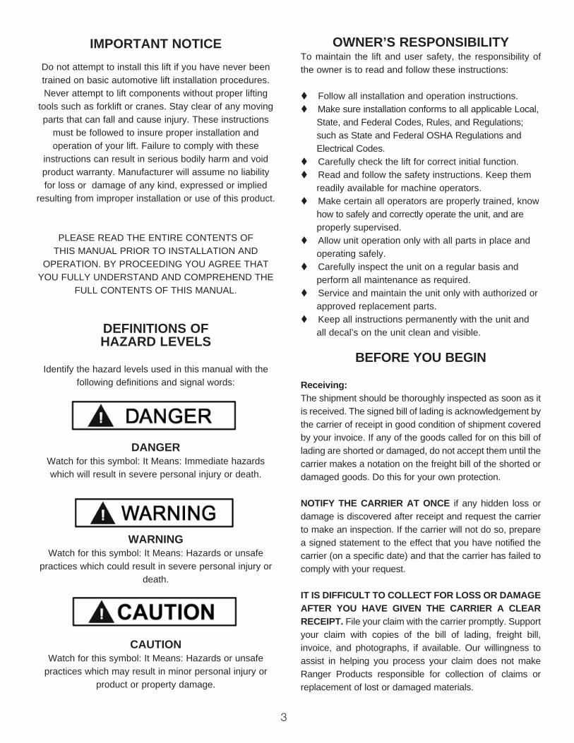
DANGERWatch for this symbol: It Means: Immediate hazards which will result in severe personal injury or death.
WARNINGWatch for this symbol: It Means: Hazards or unsafe
practices which could result in severe personal injury or death.
CAUTIONWatch for this symbol: It Means: Hazards or unsafe
practices which may result in minor personal injury or product or property damage.
OWNER’S RESPONSIBILITYTo maintain the lift and user safety, the responsibility of the owner is to read and follow these instructions:
t Follow all installation and operation instructions.t Make sure installation conforms to all applicable Local, State, and Federal Codes, Rules, and Regulations; such as State and Federal OSHA Regulations and Electrical Codes.t Carefully check the lift for correct initial function.t Read and follow the safety instructions. Keep them readily available for machine operators.t Make certain all operators are properly trained, know how to safely and correctly operate the unit, and are properly supervised.t Allow unit operation only with all parts in place and operating safely.t Carefully inspect the unit on a regular basis and perform all maintenance as required.t Service and maintain the unit only with authorized or approved replacement parts.t Keep all instructions permanently with the unit and all decal’s on the unit clean and visible.
BEFORE YOU BEGIN
Receiving:The shipment should be thoroughly inspected as soon as it is received. The signed bill of lading is acknowledgement by the carrier of receipt in good condition of shipment covered by your invoice. If any of the goods called for on this bill of lading are shorted or damaged, do not accept them until the carrier makes a notation on the freight bill of the shorted or damaged goods. Do this for your own protection.
NOTIFY THE CARRIER AT ONCE if any hidden loss or damage is discovered after receipt and request the carrier to make an inspection. If the carrier will not do so, prepare a signed statement to the effect that you have notified the carrier (on a specific date) and that the carrier has failed to comply with your request.
IT IS DIFFICULT TO COLLECT FOR LOSS OR DAMAGE AFTER YOU HAVE GIVEN THE CARRIER A CLEAR RECEIPT. File your claim with the carrier promptly. Support your claim with copies of the bill of lading, freight bill, invoice, and photographs, if available. Our willingness to assist in helping you process your claim does not make Ranger Products responsible for collection of claims or replacement of lost or damaged materials.

4
TABLE OF CONTENTSContents Page No.
Warranty / Serial Number Information . . . . . . . . . . . . . . . . . . . . . . . . . . . . . . . . . . . . . . . . . . . . . . . . . . . . . . . . . . . . . . 2
Definitions of Hazard Levels . . . . . . . . . . . . . .. . . . . . . . . . . . . . . . . . . . . . . . . . . . . . . . . . . . . . . . . . . . . . . . . . . . . . . . 3
Owner’s Responsibility . . . . . . . . . . . . . . .. . . . . . . . . . . . . . . . . . . . . . . . . . . . . . . . . . . . . . . . . . . . . . . . . . . . . . . . . . . 3
Before You Begin . . . . . . . . . . . . . . . . . . . . . . . . . . . . . . . . . . . . . . . . . . . . . . . . . . . . . . . . . . . . . . . . . . . . . . . . . . . . . 3
Installer/Operator Agreement/ Protective Equipment . . . . . . . . . . . . . . . . . . . . . . . . . . . . . . . . . . . . . . . . . . . . . . . . . 5
Introduction . . . . . . . . . . . . . . . . . . . . . . . . . . . . . . . . . . . . . . . . . . . . . . . . . . . . . . . . . . . . . . . . . . . . . . . . . . . . . . . . . . 6
Safety / Warning Instructions . . . . . . . . . . . . . . . . . . . . . . . . . . . . . . . . . . . . . . . . . . . . . . . . . . . . . . . . . . . . . . . . . . . . . 6
Tools Required . . . . . . . . . . . . . . . . . . . . . . . . . . . . . . . . . . . . . . . . . . . . . . . . . . . . . . . . . . . . . . . . . . . . . . . . . . . . . . . 7
Step 1 / Selecting Site . . . . . . . . . . . . . . . . . . . . . . . . . . . . . . . . . . . . . . . . . . . . . . . . . . . . . . . . . . . . . . . . . . . . . . . . . . 7
Step 2 / Floor Requirements . . . . . . . . . . . . . . . . . . . . . . . . . . . . . . . . . . . . . . . . . . . . . . . . . . . . . . . . . . . . . . . . . . . 7
Concrete Specifications . . . . . . . . . . . . . . . . . . . . . . . . . . . . . . . . . . . . . . . . . . . . . . . . . . . . . . . . . . . . . . . . . . . . . . 7
Assembly View / Description of Parts . . . . . . . . . . . . . . . . . . . . . . . . . . . . . . . . . . . . . . . . . . . . . . . . . . . . . . . . . . . . . . 8
Floor Plan / General Specifications . . . . . . . . . . . . . . . . . . . . . . . . . . . . . . . . . . . . . . . . . . . . . . . . . . . . . . . . . . . . . . 9-11
Clearances . . . . . . . . . . . . . . . . . . . . . . . . . . . . . . . . . . . . . . . . . . . . . . . . . . . . . . . . . . . . . . . . . . . . . . . . . . . . . . . 12
Step 3 / Closeout Side Post Installation . . . . . . . . . . . . . . . . . . . . . . . . . . . . . . . . . . . . . . . . . . . . . . . . . . . . . . 13-14
Step 4 / Ramp Assembly . . . . . . . . . . . . . . . . . . . . . . . . . . . . . . . . . . . . . . . . . . . . . . . . . . . 15-16
Step 5 / Power Side Post Installation . . . . . . . . . . . . . . . . . . . . . . . . . . . . . . . . . . . . . . . . . . . . . . . . . . . . . . . . 16-18
Step 6 / Cable / Sheave Installation . . . . . . . . . . . . . . . . . . . . . . . . . . . . . . . . . . . . . . . . . . . . . . . . . . . . . . 18-23
Electrical Wiring . . . . . . . . . . . . . . . . . . . . . . . . . . . . . . . . . . . . . . . . . . . . . . . . . . . . . . . . . . . . . 24-25
Step 7 / Power Unit Electrical Connection / Mounting the Control Panel . . . . . . . . . . . . . . . . . . . . . . . . . . . 26
Step 8 / Hydraulic Fittings . . . . . . . . . . . . . . . . . . . . . . . . . . . . . . . . . . . . . . . . . . . . . . . . . . . . . . . . 26-27
Step 9 / Hydraulic Hose Routing . . . . . . . . . . . . . . . . . . . . . . . . . . . . . . . . . . . . . . . . . . . . . . . . . . . . . 27-29
Step 10 / Lift Start-Up / Final Adjustments . . . . . . . . . . . . . . . . . . . . . . . . . . . . . . . . . . . . . . . . . 30
Step 11 / Bleeding the Cylinder . . . . . . . . . . . . . . . . . . . . . . . . . . . . . . . . . . . . . . . . . . . . . . . . . 31
Post Installation Checklist . . . . . . . . . . . . . . . . . . . . . . . . . . . . . . . . . . . . . . . . . . . . . . . . . . . . . . . . . . . . 31
Step 12 / Operation . . . . . . . . . . . . . . . . . . . . . . . . . . . . . . . . . . . . . . . . . . . . . . . . . . 31
Wire Rope Inspection and Maintenance . . . . . . . . . . . . . . . . . . . . . . . . . . . . . . . . . . . . . . . . . . . . . 32
Safe Lift Operation . . . . . . . . . . . . . . . . . . . . . . . . . . . . . . . . . . . . . . . . . . . . . . . . . . . . . . . . . . . . 33-34
Troubleshooting Guide . . . . . . . . . . . . . . . . . . . . . . . . . . . . . . . . . . . . . . . . . . . . . . . . . . . . . . . . 37-41
Maintenance Records . . . . . . . . . . . . . . . . . . . . . . . . . . . . . . . . . . . . . . . . . . . . . . . . . . . . . 42
Installation Form . . . . . . . . . . . . . . . . . . . . . . . . . . . . . . . . . . . . . . . . . . . . . . . . . . . . . . . . . . . . . . . 43
Part Number Lists . . . . . . . . . . . . . . . . . . . . . . . . . . . . . . . . . . . . . . . . . . . . . . . . . . . . . . . . 44-63
5
INSTALLER / OPERATORPLEASE READ AND FULLY
UNDERSTAND. BY PROCEEDING YOU AGREE TO THE FOLLOWING.
t I have visually inspected the site where the lift is to be installed and verified the concrete to be in good condition and free of cracks or other defects. I understand that install-ing a lift on cracked or defective concrete could cause lift failure resulting in personal injury or death.
t I understand that a level floor is required for proper installation and level lifting.
t I understand that I am responsible if my floor is of ques-tionable slope and that I will be responsible for all charges related to pouring a new level concrete slab if required and any charges.
t I understand that BendPak lifts are supplied with concrete fasteners meeting the criteria of the American National Standard “Automotive Lifts - Safety Requirements for Construction, Testing, and Validation” ANSI/ALI ALCTV-2011, and that I will be responsible for all charges related to any special, regional, structural, and/or seismic anchor-ing requirements specified by any other agencies and/or codes such as the Uniform Building Code (UBC) and/or International Building Code (IBC).
t I will assume full responsibility for the concrete floor and condition thereof, now or later, where the above equipment model is to be installed. Failure to follow Danger, Warning, and Caution instructions may lead to serious personal injury or death to operator or bystander or damage to property.
t I understand that BendPak lifts are designed to be installed in indoor locations. Contact factory for outdoor use requirements. Failure to follow installation instructions may lead to serious personal injury or death to operator or bystander or damage to property or lift.
Failure to follow Danger, Warning, and Caution instructions may lead to
serious personal injury or death to operator or bystander or damage to property.
Please read the entire manual prior to installation.Do not operate this machine until you have read and
have understood all of the Danger, Warning and Caution alerts in this manual. For additional copies
or further information, contact:
BendPak Inc.1645 Lemonwood Dr.
Santa Paula, CA. 93060
1-805-933-9970
www.bendpak.com
INSTALLER / OPERATORPROTECTIVE EQUIPMENT
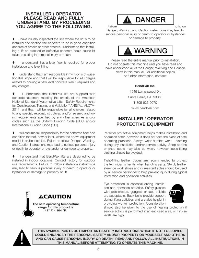
Personal protective equipment helps makes installation and operation safer, however, it does not take the place of safe operating practices. Always wear durable work clothing during any installation and/or service activity. Shop aprons or shop coats may also be worn, however loose-fitting clothing should be avoided.
Tight-fitting leather gloves are recommended to protect the technician’s hands when handling parts. Sturdy leather steel-toe work shoes and oil resistant soles should be used by all service personnel to help prevent injury during typical installation and operation activities.
Eye protection is essential during installa-tion and operation activities. Safety glasses with side shields, goggles, or face shields are acceptable. Back belts provide support during lifting activities and are also helpful in providing worker protection. Consideration should also be given to the use of hearing protection if service activity is performed in an enclosed area, or if noise levels are high.
THIS SYMBOL POINTS OUT IMPORTANT SAFETY INSTRUCTIONS WHICH IF NOT FOLLOWEDCOULD ENDANGER THE PERSONAL SAFETY AND/OR PROPERTY OR YOURSELF AND OTHERSAND CAN CAUSE PERSONAL INJURY OR DEATH. READ AND FOLLOW ALL INSTRUCTIONS IN
THIS MANUAL BEFORE ATTEMPTING TO OPERATE THIS MACHINE.

6
1. Carefully remove the crating and packing materials. CAUTION! Be careful when cutting steel banding material as items may become loose and fall causing personal harm or injury.
2. Check the voltage, phase, and proper amperage require-ments for the motor shown on the motor plate. Electrical work should be performed only by a certified electrician.
IMPORTANT SAFETY INSTRUCTIONSRead these safety instructions entirely. Do not attempt to install this lift if you have never been trained on
basic automotive lift installation procedures. Never attempt to lift components without proper lifting tools such as forklift or cranes. Stay clear of any moving parts that may fall and cause injury. When using your garage equipment, basic
safety precautions should always be followed, including the following:
INTRODUCTION
1. Read and understand all instructions and all safety warn-ings before operating lift.2. Care must be taken as burns can occur from touching hot parts.3. Do not operate equipment with a damaged cord or if the equipment has been dropped or damaged until it has been examined by a qualified service person.4. If an extension cord is necessary, a cord with a current rating equal to or more than that of the equipment should be used. Cords rated for less current than the equipment may overheat. Care should be taken to arrange the cord so that it will not be tripped over or pulled.5. Always unplug equipment from electrical outlet when not in use. Never use the cord to pull the plug from the outlet. Grasp plug and pull to disconnect.6. To reduce the risk of fire, do not operate equipment in the vicinity of open containers of flammable liquids (gasoline).7. Adequate ventilation should be provided when working on operating internal combustion engines.8. Keep hair, loose clothing, fingers, and all parts of body away from moving parts. Keep feet clear of lift when lowering. Avoid pinch points.9. DANGER! To reduce the risk of elec-tric shock, do not use on wet surfaces or expose to rain. The power unit used on this lift contains high voltage. Disconnect power at the receptacle or at the circuit breaker switch before performing any elec-trical repairs. Secure plug so that it cannot be accidentally plugged in during service, or mark circuit breaker switch so that it cannot be accidentally switched on during service.10. Use only as described in this manual. Use only manufac-turer’s recommended attachments.11. ALWAYS WEAR SAFETY GLASSES. Everyday eyeglasses only have impact resistant lenses, they are not safety glasses.12. Consider work environment. Keep work area clean. Cluttered work areas invite injuries. Keep areas well lit.13. Guard against electric shock. This lift must be grounded while in use to protect operator from electric shock. Never connect the green power cord wire to a live terminal. This is for
ground only.14. Only trained operators should operate this lift. All non-trained personnel should be kept away from the work area. Never let non-trained personnel come in contact with, or oper-ate lift.15. DO NOT override self-closing lift controls.16. Clear area if vehicle is in danger of falling.17. ALWAYS make sure the safeties are engaged before attempting to work on or near a vehicle.18. WARNING! RISK OF EXPLOSION. This equipment has internal arcing or sparking parts which should not be exposed to flammable vapors. This machine should not be located in a recessed area or below floor level.19. MAINTAIN WITH CARE. Keep lift clean for better and safer performance. Follow manual for proper lubrication and maintenance instructions. Keep control handles and/or buttons dry, clean and free from grease and oil.20. Check for damaged parts. Check for alignment of mov-ing parts, breakage of parts or any condition that may affect operation of lift. Do not use lift if any component is broken or damaged.21. NEVER remove safety related components from the lift. Do not use lift if safety related components are missing or dam-aged.22. STAY ALERT. Use common sense and watch what you are doing. Remember, SAFETY FIRST.23. Installation of this lift requires lifting of very heavy com-ponents. Be sure to use the correct lifting tools such as forklifts or cranes to position components. Pay attention to components position once components are lifted. Once lifted, components are falling hazards. Failure to use the correct lifting tools or to pay attention during lifting may result in personal injury or death. A minimum of a two person installation team is recommended for safe lifting practices.
SAVE THESE INSTRUCTIONS
7
STEP 1(Selecting Site)
Before installing your new lift, check the following.
1. LIFT LOCATION: Always use architectural plans when available. Check the layout dimension against the floor plan requirements making sure that adequate space if available.
2. OVERHEAD OBSTRUCTIONS: The area where the lift will be located should be free of overhead obstructions such as heaters, building supports, electrical lines etc.
3. DEFECTIVE FLOOR: Visually inspect the site where the lift is to be installed and check for cracked or defective concrete.
4. OPERATING TEMPERATURE. Operate lift only between temperatures of 41° -104° F.
STEP 2(Floor Requirements)
This lift must be installed on a solid level concrete floor with
no more than 3-degrees of slope. Failure to do so could cause personal injury or death.
A level floor is suggested for proper use and installation and level lifting. If a floor is of questionable slope, consider a survey of the site and/or the possibility of pouring a new level concrete slab.
t DO NOT install or use this lift on any asphalt surface or any surface other than concrete.
t DO NOT install or use this lift on expansion seams or on cracked or defective concrete.
t DO NOT install or use this lift on a second / elevated floor without first consulting building architect.
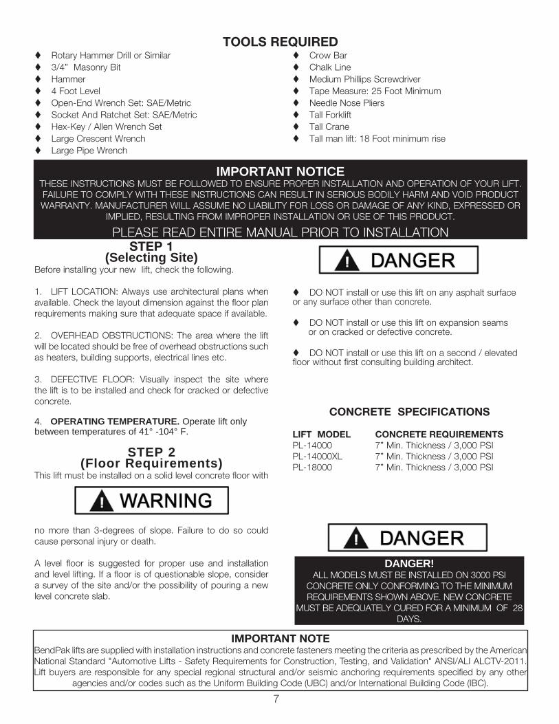
CONCRETE SPECIFICATIONS
LIFT MODEL CONCRETE REQUIREMENTSPL-14000 7” Min. Thickness / 3,000 PSIPL-14000XL 7” Min. Thickness / 3,000 PSIPL-18000 7” Min. Thickness / 3,000 PSI
DANGER!ALL MODELS MUST BE INSTALLED ON 3000 PSI
CONCRETE ONLY CONFORMING TO THE MINIMUM REQUIREMENTS SHOWN ABOVE. NEW CONCRETE
MUST BE ADEQUATELY CURED FOR A MINIMUM OF 28 DAYS.
IMPORTANT NOTICETHESE INSTRUCTIONS MUST BE FOLLOWED TO ENSURE PROPER INSTALLATION AND OPERATION OF YOUR LIFT. FAILURE TO COMPLY WITH THESE INSTRUCTIONS CAN RESULT IN SERIOUS BODILY HARM AND VOID PRODUCT WARRANTY. MANUFACTURER WILL ASSUME NO LIABILITY FOR LOSS OR DAMAGE OF ANY KIND, EXPRESSED OR
IMPLIED, RESULTING FROM IMPROPER INSTALLATION OR USE OF THIS PRODUCT.
PLEASE READ ENTIRE MANUAL PRIOR TO INSTALLATION
t Rotary Hammer Drill or Similar t 3/4” Masonry Bit t Hammert 4 Foot Levelt Open-End Wrench Set: SAE/Metrict Socket And Ratchet Set: SAE/Metrict Hex-Key / Allen Wrench Sett Large Crescent Wrencht Large Pipe Wrench
t Crow Bar t Chalk Linet Medium Phillips Screwdrivert Tape Measure: 25 Foot Minimumt Needle Nose Plierst Tall Forkliftt Tall Cranet Tall man lift: 18 Foot minimum rise
TOOLS REQUIRED
IMPORTANT NOTEBendPak lifts are supplied with installation instructions and concrete fasteners meeting the criteria as prescribed by the American National Standard "Automotive Lifts - Safety Requirements for Construction, Testing, and Validation" ANSI/ALI ALCTV-2011. Lift buyers are responsible for any special regional structural and/or seismic anchoring requirements specified by any other
agencies and/or codes such as the Uniform Building Code (UBC) and/or International Building Code (IBC).
8
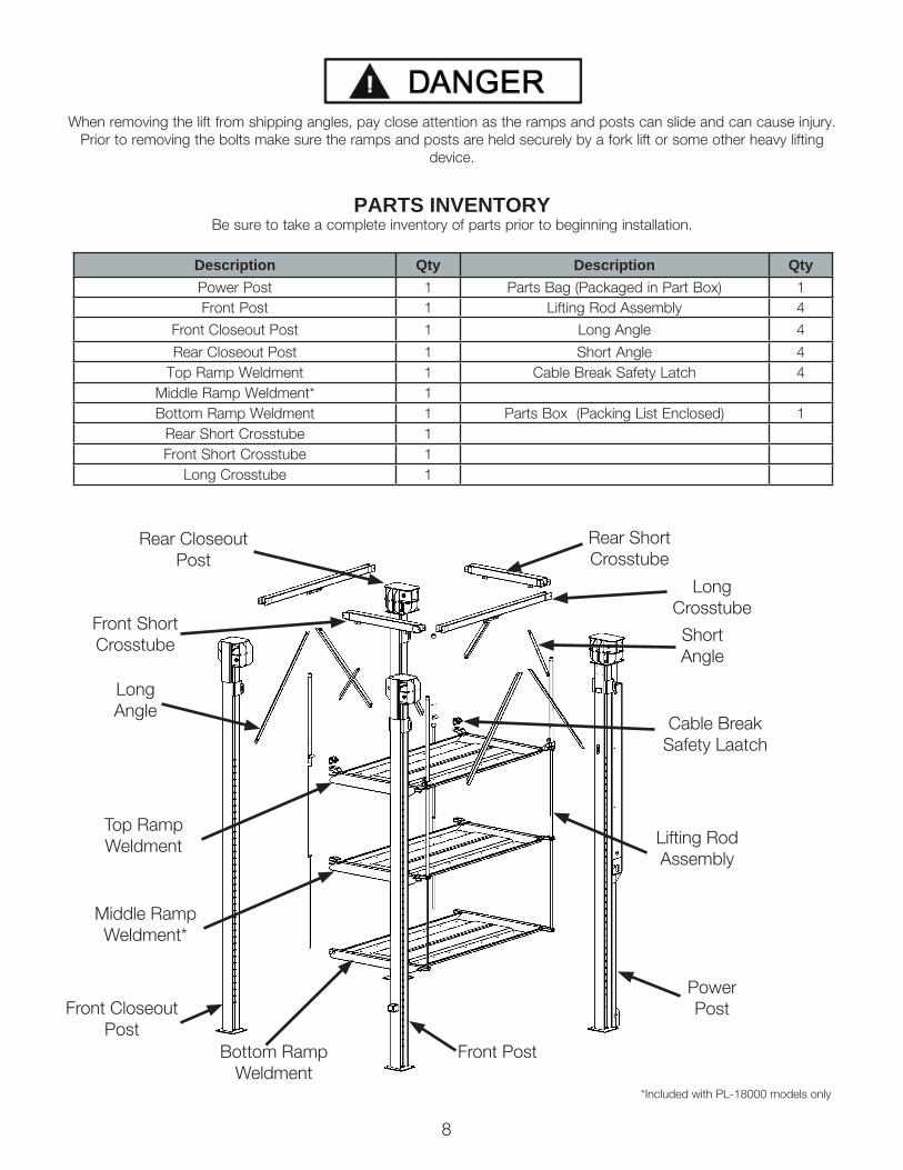
When removing the lift from shipping angles, pay close attention as the ramps and posts can slide and can cause injury. Prior to removing the bolts make sure the ramps and posts are held securely by a fork lift or some other heavy lifting
device.
PARTS INVENTORYBe sure to take a complete inventory of parts prior to beginning installation.
Description Qty Description QtyPower Post 1 Parts Bag (Packaged in Part Box) 1Front Post 1 Lifting Rod Assembly 4
Front Closeout Post 1 Long Angle 4
Rear Closeout Post 1 Short Angle 4Top Ramp Weldment 1 Cable Break Safety Latch 4
Middle Ramp Weldment* 1Bottom Ramp Weldment 1 Parts Box (Packing List Enclosed) 1
Rear Short Crosstube 1Front Short Crosstube 1
Long Crosstube 1
Bottom Ramp Weldment
Lifting Rod Assembly
Top Ramp Weldment
Middle Ramp Weldment*
*Included with PL-18000 models only
Power Post
Short Angle
Long Angle
Long Crosstube
Rear Short Crosstube
Front Short Crosstube
Front Closeout Post
Rear Closeout Post
Cable Break Safety Laatch
Front Post
9
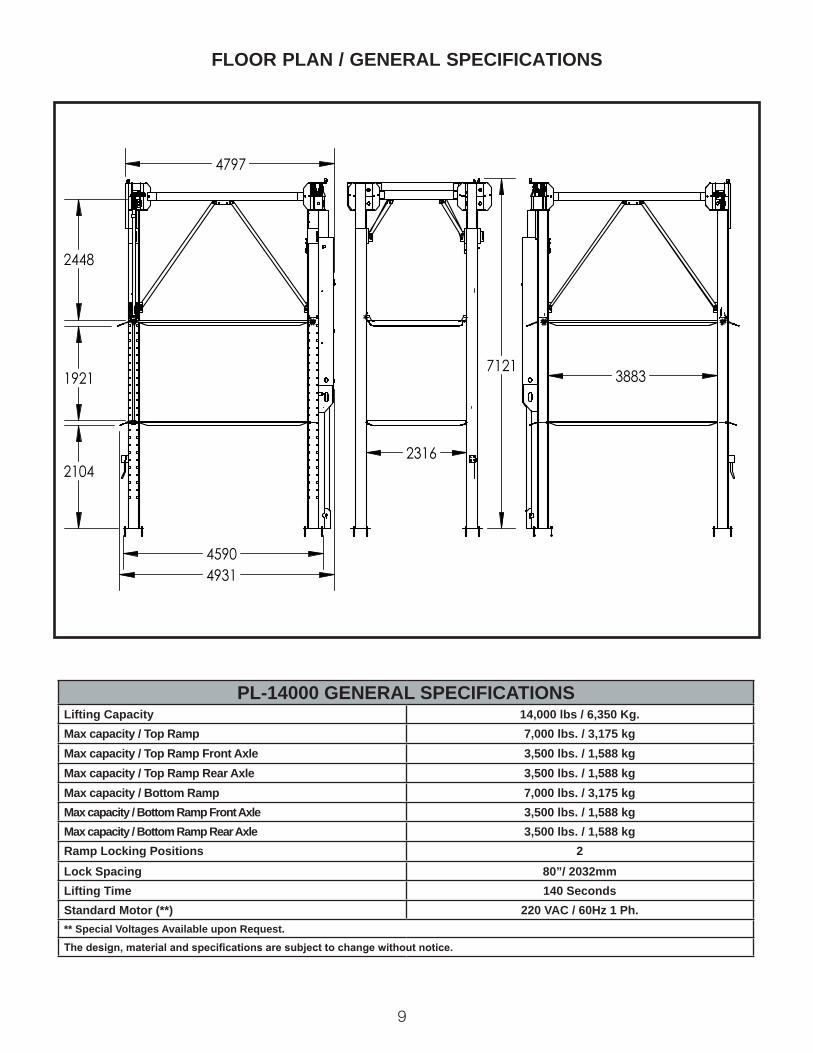
FLOOR PLAN / GENERAL SPECIFICATIONS
PL-14000 GENERAL SPECIFICATIONSLifting Capacity 14,000 lbs / 6,350 Kg.Max capacity / Top Ramp 7,000 lbs. / 3,175 kg Max capacity / Top Ramp Front Axle 3,500 lbs. / 1,588 kg Max capacity / Top Ramp Rear Axle 3,500 lbs. / 1,588 kgMax capacity / Bottom Ramp 7,000 lbs. / 3,175 kgMax capacity / Bottom Ramp Front Axle 3,500 lbs. / 1,588 kgMax capacity / Bottom Ramp Rear Axle 3,500 lbs. / 1,588 kgRamp Locking Positions 2Lock Spacing 80”/ 2032mmLifting Time 140 SecondsStandard Motor (**) 220 VAC / 60Hz 1 Ph.** Special Voltages Available upon Request.The design, material and specifications are subject to change without notice.
4797
2448
1921
2104
4590 4931
7121
2316
3883

10
FLOOR PLAN / GENERAL SPECIFICATIONS
5305
2448
2099
5098
1904
5439
7121
2317 4391
PL-14000XL GENERAL SPECIFICATIONSLifting Capacity 14,000 lbs / 6,350 Kg.Max capacity / Top Ramp 7,000 lbs. / 3,175 kg Max capacity / Top Ramp Front Axle 3,500 lbs. / 1,588 kg Max capacity / Top Ramp Rear Axle 3,500 lbs. / 1,588 kgMax capacity / Bottom Ramp 7,000 lbs. / 3,175 kgMax capacity / Bottom Ramp Front Axle 3,500 lbs. / 1,588 kgMax capacity / Bottom Ramp Rear Axle 3,500 lbs. / 1,588 kgRamp Locking Positions 2Lock Spacing 80”/ 2032mmLifting Time 140 SecondsStandard Motor (**) 220 VAC / 60Hz 1 Ph.** Special Voltages Available upon Request.The design, material and specifications are subject to change without notice.

11
FLOOR PLAN / GENERAL SPECIFICATIONS
4797
4590
2484
1933
1954
1996
4931
9144
2313
3023
3883
PL-18000 GENERAL SPECIFICATIONSLifting Capacity 18,000 lbs / 8,164 KgMax capacity / Top Ramp 6,000 lbs / 2,721 kg Max capacity / Top Ramp Front Axle 3,000 lbs / 1,360 kgMax capacity / Top Ramp Rear Axle 3,000 lbs / 1,360 kgMax capacity / Middle Ramp 6,000 lbs / 2,721 kg Max capacity / Middle Ramp Front Axle 3,000 lbs / 1,360 kgMax capacity / Middle Ramp Rear Axle 3,000 lbs / 1,360 kgMax capacity / Bottom Ramp 6,000 lbs / 2,721 kg Max capacity / Bottom Ramp Front Axle 3,000 lbs / 1,360 kgMax capacity / Bottom Ramp Rear Axle 3,000 lbs / 1,360 kgRamp Locking Positions 3Lock Spacing 80”/ 2032mmLifting Time 210 SecondsStandard Motor (**) 220 VAC / 60Hz 1 Ph.** Special Voltages Available upon Request.The design, material and specifications are subject to change without notice.

12
LIFT HEIGHT CLEARNACE NOTE: There must be a 3” MIN distance from the top of the parking lift to the near-est obstruction or ceiling.
CLEARANCESPL-14000/18000

13
STEP 3(Closeout Side Post Installation)
1. Place a chalk lines on the floor according to the floor plan layout. Be sure to take correct “Rear” clearance spacing into consideration for the Hydraulic Power Unit. (See Fig 3.1)
2. Locate the Front and Rear Closeout Posts. Using a forklift or crane lay them next to each other on the floor oriented so that the base plates are on the same side and the Crosstube Clevises are oriented inward. (See Fig 3.2)NOTE: If sheaves were factory installed, it will be helpful to remove the Cable Sheaves from each post prior to raising.
3. Using a forklift or crane, lift the Rear Closeout Post up-right and place it into position on the “Rear - Closeout Side” using the chalk lines that were marked earlier in this step. DO NOT remove forklift or crane once post is upright. (See Fig 3.3)
4. Using the baseplate as a guide, drill each anchor hole in the concrete approximately 7” deep using a rotary hammer drill and 3/4” concrete drill-bit. (See Fig 3.4)
5. After drilling the anchor holes, remove the dust thor-oughly from each hole using compressed air and/or wire brush.
6. Assemble the washers and nuts on the anchors then tap into each hole with a hammer until the washer rests against the base. Be sure that enough threads are left exposed, if shimming is required. (See Fig. 3.5)
7. If shimming is required, insert the shims as necessary around each anchor bolt. (See Fig. 3.6)
WARNING!THIS STEP REQUIRES LIFTING OF VERY HEAVY COMPONENTS. BE SURE TO USE THE CORRECT
LIFTING TOOLS SUCH AS FORKLIFTS OR CRANES TO POSITION COMPONENTS. PAY ATTENTION TO
COMPONENTS POSITION ONCE COMPONENTS ARE LIFTED. ONCE LIFTED, COMPONENTS
ARE FALLING HAZARDS. FAILURE TO USE THE CORRECT LIFTING TOOLS OR TO PAY ATTENTION
DURING LIFTING MAY RESULT IN PERSONAL INJURY OR DEATH. A MINIMUM OF A TWO PERSON INSTALLATION TEAM IS RECOMMENDED FOR SAFE
LIFTING PRACTICES.
Fig 3.1
“Approach”“Closeout Side”
“Power Side”“Rear”
Fig 3.3
7
Fig 3.4
Fig 3.5
Fig 3.2Crosstube Clevises
NOTE: Base Plates are oriented in same direction.
14
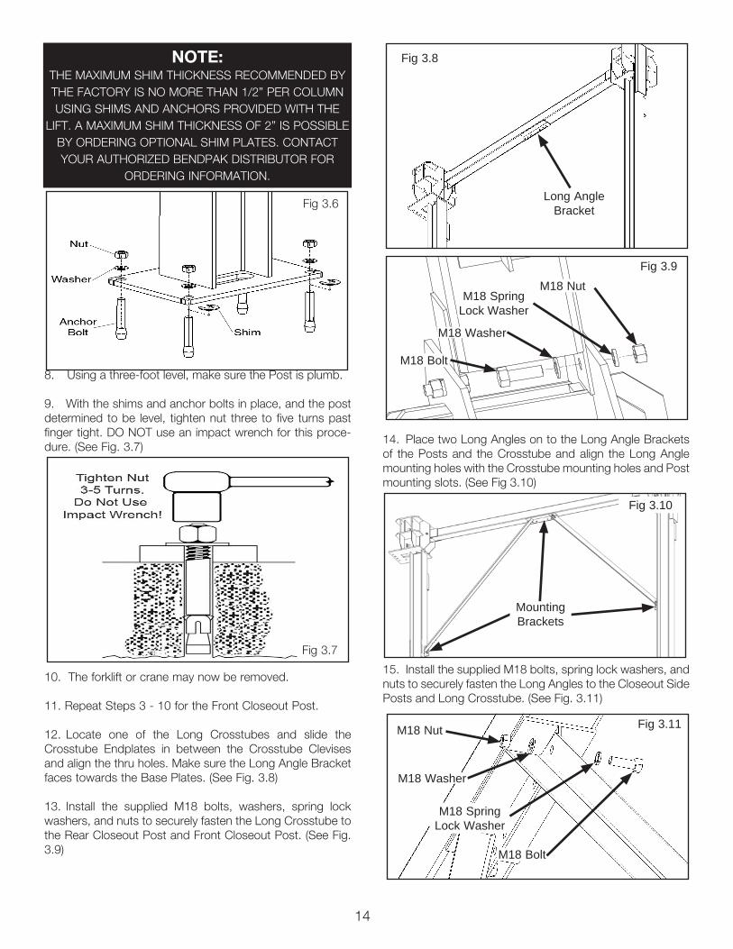
8. Using a three-foot level, make sure the Post is plumb.
9. With the shims and anchor bolts in place, and the post determined to be level, tighten nut three to five turns past finger tight. DO NOT use an impact wrench for this proce-dure. (See Fig. 3.7)
10. The forklift or crane may now be removed.
11. Repeat Steps 3 - 10 for the Front Closeout Post.
12. Locate one of the Long Crosstubes and slide the Crosstube Endplates in between the Crosstube Clevises and align the thru holes. Make sure the Long Angle Bracket faces towards the Base Plates. (See Fig. 3.8)
13. Install the supplied M18 bolts, washers, spring lock washers, and nuts to securely fasten the Long Crosstube to the Rear Closeout Post and Front Closeout Post. (See Fig. 3.9)
14. Place two Long Angles on to the Long Angle Brackets of the Posts and the Crosstube and align the Long Angle mounting holes with the Crosstube mounting holes and Post mounting slots. (See Fig 3.10)
15. Install the supplied M18 bolts, spring lock washers, and nuts to securely fasten the Long Angles to the Closeout Side Posts and Long Crosstube. (See Fig. 3.11)
Fig 3.8
Long Angle Bracket
Fig 3.10
Mounting Brackets
Fig 3.9M18 Nut
M18 Spring Lock Washer
M18 Bolt
M18 Washer
Fig 3.11M18 Nut
M18 Spring Lock Washer
M18 Bolt
M18 Washer
Fig 3.6
NOTE: THE MAXIMUM SHIM THICKNESS RECOMMENDED BY THE FACTORY IS NO MORE THAN 1/2” PER COLUMN USING SHIMS AND ANCHORS PROVIDED WITH THE
LIFT. A MAXIMUM SHIM THICKNESS OF 2” IS POSSIBLE BY ORDERING OPTIONAL SHIM PLATES. CONTACT YOUR AUTHORIZED BENDPAK DISTRIBUTOR FOR
ORDERING INFORMATION.
Fig 3.7

15
STEP 4(Ramp Assembly)
NOTE: The PL-18000 model is depicted throughout this step. Disregard any instruction regarding “Middle
Ramp” for PL-14000 installation.1. Locate the Ramp Weldments. Using a forklift, lift the Top Ramp Weldment and set the ramp down onto the Middle Ramp Weldment and the Middle Ramp Weldment onto the Bottom Ramp Weldment. It may be helpful to set the ramps down on to wood blocks to help unload the ramps from the forklift. Align the thru holes in the ramps as closely as pos-sible. (See Fig 4.1)
2. Locate the Cable Break Safety Latches. Align the mounting holes of the Cable Break Safety Latches with the mount-ing holes of the Top Ramp Weldment. Fasten the two com-ponents together using the provided clevis pins, snap rings and set screws. Repeat on all 4 corners. (See Fig 4.2)
3. Locate the Lifting Rod Assemblies and disassemble the Lifting Collars and the Cable Retainers. (See Fig 4.3)
4. Insert the Lifting Collar through the bottom of the Top Ramp Weldment. Inset the Middle Lifting Collar through the bottom of the Middle Ramp Weldment. (See Fig 4.4)
5. Take the Lifting Rod Assemblies that were disassem-bled in Item 3 and align the rod and tubes with the thru holes of the Cable Break Safety Assembly and the ramps. Ap-ply loctite to the tube threads before assembling the collars. Hold the Large Lifting Tube in place as the Lifting Collar is threaded on. (See Fig 4.5)
Fig 4.2
Fig 4.1
Fig 4.3
Fig 4.4
Fig 4.5
Top Lifting Collar
Lifting Collar
Middle Lifting Collar
PL-14000 Lifting Rod Assembly
PL-18000 Lifting Rod Assembly
Cable Retainer
Cable Break Safety Latch
Set Screw
Clevis Pin
Snap Ring
Lifting Collar
Middle Lifting Collar
Large Lifting Tube
Middle Lifting Tube
Cable Break Safety Assembly
Lifting Collar
Middle Lifting Collar
Lifting Rod

16
6. Attach the large and small Cable Break Safety Springs. (See Fig 4.6)
7. When the Lifting Rod is through the Bottom Ramp Weldment fasten a nylock nut and washer to the end of each Lifting Rod. (See Fig 4.7)
9. Using a forklift, lift the Ramp Weldments and move them so that the ends of the Ramp Weldments fit inside of the posts. It may be helpful to set the ramps on wood blocks to help unload the ramp from the forklift. (See Fig. 4.8)
STEP 5(Power Side Post Installation)
1. Locate the Power Post, easily identified by the cylin-der assembled in the post or the Sheave Pullbox mounted inside of the post. Orient the Power Post so that the Sheave Pullbox Glide Channel is easily accessible.(See Fig. 5.1)
2. Inspect the ends of the Safety Spring inside the Sheave Pullbox as shown. Make sure the spring ends are secure at both ends. DO NOT ATTEMPT TO RAISE THE LIFT UNTIL THE SAFETY SPRING IS ATTACHED AND THE ROLLER IS PULLED TOWARDS THE SAFETY BAR BY THE SPRING. (See Fig 5.2)
3. Locate the Safety Cable Connector, spacer and bolt in the parts bag. Assemble them through the top hole of the safety bar as shown in Figure 5.3.
4. Position the Power Post so that the post is laying on its side with the cylinder side facing to the rear of the instal-lation area. It may be helpful to position this post relatively close to its final position to ease installation later. (See Fig. 5.4)
5. Position the Front Post so that the post is laying on its side with the Control Box facing the Approach Side. It may be helpful to position this post relatively close to its final posi-tion to ease installation later. (See Fig. 5.5)
Fig 4.8
Fig 4.7
Bottom Ramp Weldment
1-1/8” Washer
1-1/8” Nylock Nut
Fig 5.1
Fig 5.2 Safety Bar
Roller
Safety Spring
Note: Cut-away view for clarification.
Fig 4.6
Large Cable Break Safety
Spring
Small Cable Break Safety Spring
17
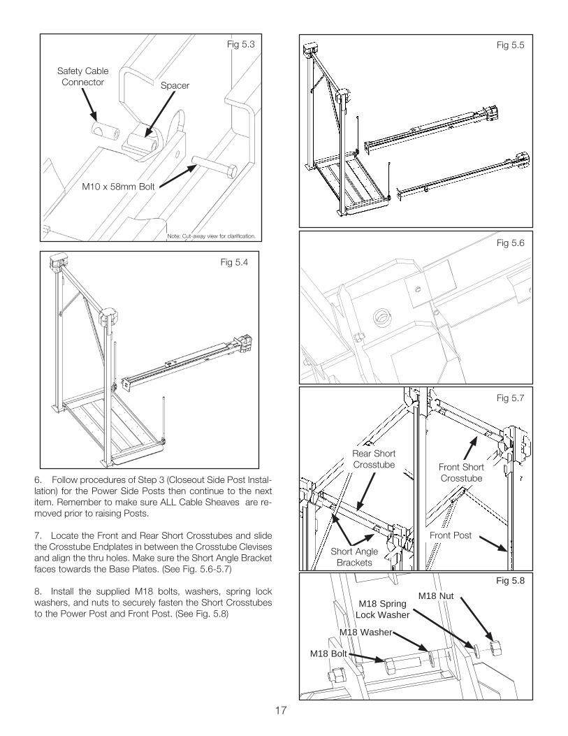
6. Follow procedures of Step 3 (Closeout Side Post Instal-lation) for the Power Side Posts then continue to the next item. Remember to make sure ALL Cable Sheaves are re-moved prior to raising Posts.
7. Locate the Front and Rear Short Crosstubes and slide the Crosstube Endplates in between the Crosstube Clevises and align the thru holes. Make sure the Short Angle Bracket faces towards the Base Plates. (See Fig. 5.6-5.7)
8. Install the supplied M18 bolts, washers, spring lock washers, and nuts to securely fasten the Short Crosstubes to the Power Post and Front Post. (See Fig. 5.8)
Fig 5.4
Fig 5.5
Fig 5.6
Fig 5.3
M10 x 58mm Bolt
Spacer
Safety Cable Connector
Note: Cut-away view for clarification.
Fig 5.7
Front Short Crosstube
Rear Short Crosstube
Front Post
Short Angle Brackets
Fig 5.8M18 Nut
M18 Spring Lock Washer
M18 Bolt
M18 Washer

18
9. Place Short Angles on to the Short Angle Brackets of the Posts and the Crosstube and align the Short Angle mounting holes with the Crosstube mounting holes and Post mounting slots. (See Fig 5.9)NOTE: There are two Front Short Angles and two Longer Rear Short Angles. Make sure that the Longer Short Angles are installed at the REAR of the lift.
10. Install the supplied M18 bolts, spring lock washers, and nuts to securely fasten the Short Angles to the Front Post, Power Post, and Short Crosstubes. (See Fig. 5.10)
11. Make sure both ramp tabs are aligned inside both posts. (See Fig 5.11)
14. Using a three-foot level, make sure the Power Side and Front Posts are plumb.
15. Using the base of the frame as a guide, drill each anchor hole and anchor the Power Side and Front Posts following the procedures at the end of Step 3. Shim posts if necessary.
16. The forklift or crane may now be removed.
STEP 6
(Cable / Sheave Installation) 1. In order to install the cables, it is necessary to first
extend the Hydraulic Cylinder. Remove both cylinder port plugs, then use an rubber tipped air gun or ratcheting pull-strap to extend the cylinder. (See Fig 6.1)2. Once cylinder is extended, attach cables by anchor-
ing the threaded end connectors through the Sheave Box Bottom Plate along with the provided hardware. Use the diagram to route the cables around the correct sheaves. Route cables from outside of sheave to inside post. (See Fig 6.2)
Fig 5.10
Fig 5.9
Rear Short Angle
Front Short Angle
Fig 5.11
M18 Nut
M18 Spring Lock Washer
M18 Bolt
M18 Washer
Fig 6.1
Apply Air Here
WARNING!DO NOT EXCEED 50 PSI. IF CYLINDER DOES NOT MOVE
IMMEDIATELY STOP AND USE A COME-ALONG OR OTHER PULLING DEVISE. KEEP HANDS CLEAR.
WARNING!TAKE CARE TO NOT DAMAGE THE CHROME ROD
DURING THIS STEP. DAMAGING THE CHROME ROD WILL VOID WARRANTY.
WARNING!WHEN THE CABLE ADJUSTING NUTS BOTTOM OUT ON THE THREADED END OF THE CABLE CONNECTOR AND THERE IS STILL SLACK IN
THE CABLES, THE CABLES HAVE STRETCHED BEYOND THE SAFE USEFUL LENGTH AND NEED TO BE REPLACED WITH FACTORY APPROVED
CABLE ASSEMBLIES. DO NOT PLACE WASHERS, SPACERS OR OTHER DEVICES TO “SHORTEN” THE
EFFECTIVE CABLE LENGTH AS DAMAGE TO THE LIFT OR INJURY TO PERSONS MAY OCCUR.

19
3. Route the Cables around the sheaves as they are rein-stalled. Insert 3 sheaves and 2 spacers into the bottom part of the Power Post Sheave Box and secure the sheaves with the Upper Sheave Stack Pin. Then insert 1 sheave and 2 spacers into the upper part of the Sheave Box and slide it towards the interior of the lift. Secure the top sheave with the Single Sheave Pin. Install the supplied M10 bolt and nylock nut to securely fasten the pin. (See Fig 6.3)NOTE: Failure to install FRICTION SPACERS will result in prema-ture sheave wear and void warranty.
4. To install the horizontally oriented sheave in the Front Post Sheave Box tilt it at an angle as it is slid in and rotate it once it is inside the Sheave Box. Then insert 2 sheave spacers and install the Single Sheave Pin vertically and bolt in place. Insert the lower sheave through the back of the Sheave Box with 2 spacers and secure with Single Sheave Pin and hardware. (See Fig 6.4-6.5)
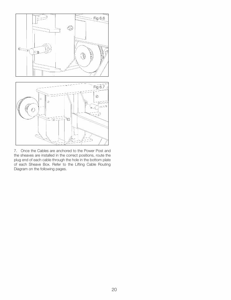
5. In the Front Closeout Post insert a sheave and 2 spac-ers into the lower part of the Sheave Box from the side of the Sheave Box and secure with a Single Sheave Pin and bolt in place. (See Fig 6.6)
6. In the Rear Closeout Post insert a sheave and 2 spac-ers into the upper part of the Sheave Box from the outside of the Sheave Box and slide it towards the interior of the lift. Secure with a Single Sheave Pin and bolt in place. (See Fig 6.7)
NOTE:THE CABLES ARE NAMED IN ORDER FROM THE
SHORTEST (A) TO THE LONGEST (D).
Fig 6.2
Cable “A”
Cable “B”
Cable “D”
Cable “C”
Sheave “A”
Sheave “C”
Sheave “D”
Sheave “B”
Sheave Box Bottom Plate
Upper Sheave
Stack Pin
Single Sheave Pin
M10 Nylock Nut
M10 Bolt
Fig 6.4
Fig 6.5
Fig 6.3
Washer and Nylock
Nut
20
7. Once the Cables are anchored to the Power Post and the sheaves are installed in the correct positions, route the plug end of each cable through the hole in the bottom plate of each Sheave Box. Refer to the Lifting Cable Routing Diagram on the following pages.
Fig 6.6
Fig 6.7

21
PL-14000/18000 LIFTING CABLE ROUTING DIAGRAM
CABLE “A” Pullbox Sheaves
Inside Post
CABLE “B” Pullbox Sheaves
Inside Post

22
CABLE “C”
CABLE “D”
PL-14000 LIFTING CABLE ROUTING DIAGRAM CONTINUED
Pullbox Sheaves
Pullbox Sheaves
Inside Post
Inside Post
23
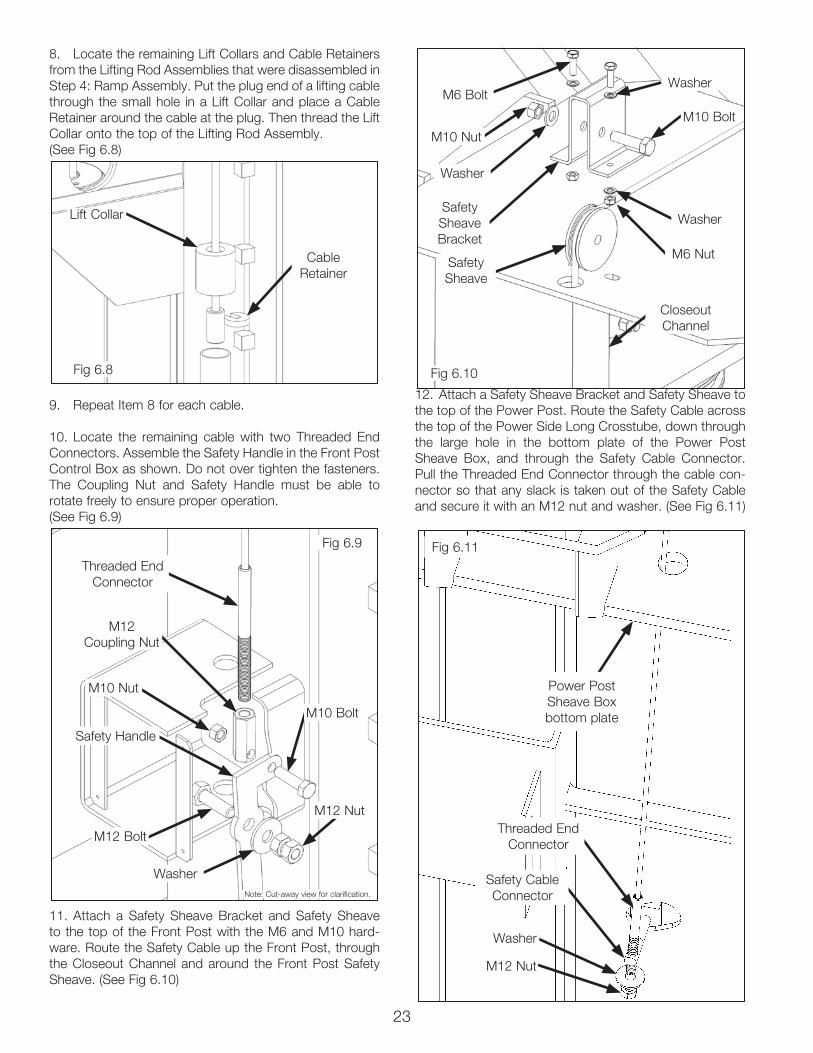
8. Locate the remaining Lift Collars and Cable Retainers from the Lifting Rod Assemblies that were disassembled in Step 4: Ramp Assembly. Put the plug end of a lifting cable through the small hole in a Lift Collar and place a Cable Retainer around the cable at the plug. Then thread the Lift Collar onto the top of the Lifting Rod Assembly. (See Fig 6.8)
9. Repeat Item 8 for each cable.
10. Locate the remaining cable with two Threaded End Connectors. Assemble the Safety Handle in the Front Post Control Box as shown. Do not over tighten the fasteners. The Coupling Nut and Safety Handle must be able to rotate freely to ensure proper operation. (See Fig 6.9)
11. Attach a Safety Sheave Bracket and Safety Sheave to the top of the Front Post with the M6 and M10 hard-ware. Route the Safety Cable up the Front Post, through the Closeout Channel and around the Front Post Safety Sheave. (See Fig 6.10)
12. Attach a Safety Sheave Bracket and Safety Sheave to the top of the Power Post. Route the Safety Cable across the top of the Power Side Long Crosstube, down through the large hole in the bottom plate of the Power Post Sheave Box, and through the Safety Cable Connector. Pull the Threaded End Connector through the cable con-nector so that any slack is taken out of the Safety Cable and secure it with an M12 nut and washer. (See Fig 6.11)
Fig 6.8
Fig 6.9 Fig 6.11
Fig 6.10
Lift Collar
Threaded End Connector
Threaded End Connector
Power Post Sheave Box bottom plate
M12 Nut
Washer
Closeout Channel
M12 Coupling Nut
Safety Sheave
Safety Cable Connector
Safety Sheave Bracket
Safety Handle
M10 Nut
M10 Nut
M6 Nut
M10 Bolt
M6 Bolt
Washer
Washer
Washer
Washer
M12 Nut
M10 Bolt
M12 Bolt
Cable Retainer
Note: Cut-away view for clarification.

24
IMPORTANT POWER-UNIT INSTALLATION NOTES
n DO NOT run power unit without oil. Damage to pump can occur.n The power unit must be kept dry. Damage to power unit caused by water or other liquids such as detergents, acid etc., is not covered under warranty.n Improper electrical connection can damage motor and will not be covered under warranty.n Motor can not run on 50HZ without a physical change in the motor.n Use a separate breaker for each power unit.n Protect each circuit with time delay fuse or circuit breaker.n For 208-230 volt, single phase, use a 25 amp fuse.n For 208-230 volt, three phase, use a 20 amp fuse.n For 380-440 volt, three phase, use a 15 amp fuse.
Installation and adjustment. DO NOT attempt to raise vehicle until a thorough operation check has been completed.
All wiring must be performed by a certified electrician only.
DANGER!DO NOT PERFORM ANY MAINTENANCE OR INSTALLATION OF ANY COMPONENTS WITH OUT FIRST ENSURING THAT ELECTRICAL POWER HAS BEEN DISCONNECTED AT THE
SOURCE OR PANEL AND CANNOT BE RE-ENERGIZED UNTIL ALL MAINTENANCE AND/OR INSTALLATION PROCEDURES
ARE COMPLETED.
SEE WIRING INSTRUCTIONS AFFIXED TO MOTOR FOR PROPER WIRING INSTRUCTIONS.
25
26
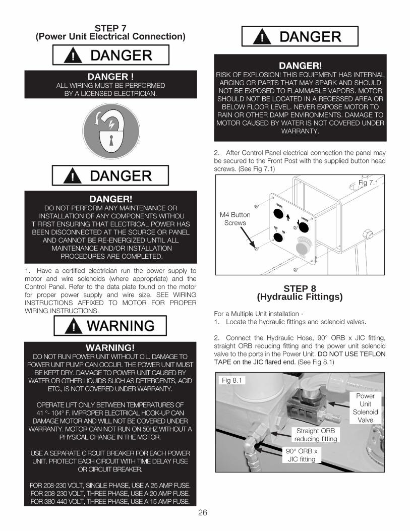
STEP 7(Power Unit Electrical Connection)
1. Have a certified electrician run the power supply to motor and wire solenoids (where appropriate) and the Control Panel. Refer to the data plate found on the motor for proper power supply and wire size. SEE WIRING INSTRUCTIONS AFFIXED TO MOTOR FOR PROPER WIRING INSTRUCTIONS.
2. After Control Panel electrical connection the panel may be secured to the Front Post with the supplied button head screws. (See Fig 7.1)
STEP 8(Hydraulic Fittings)
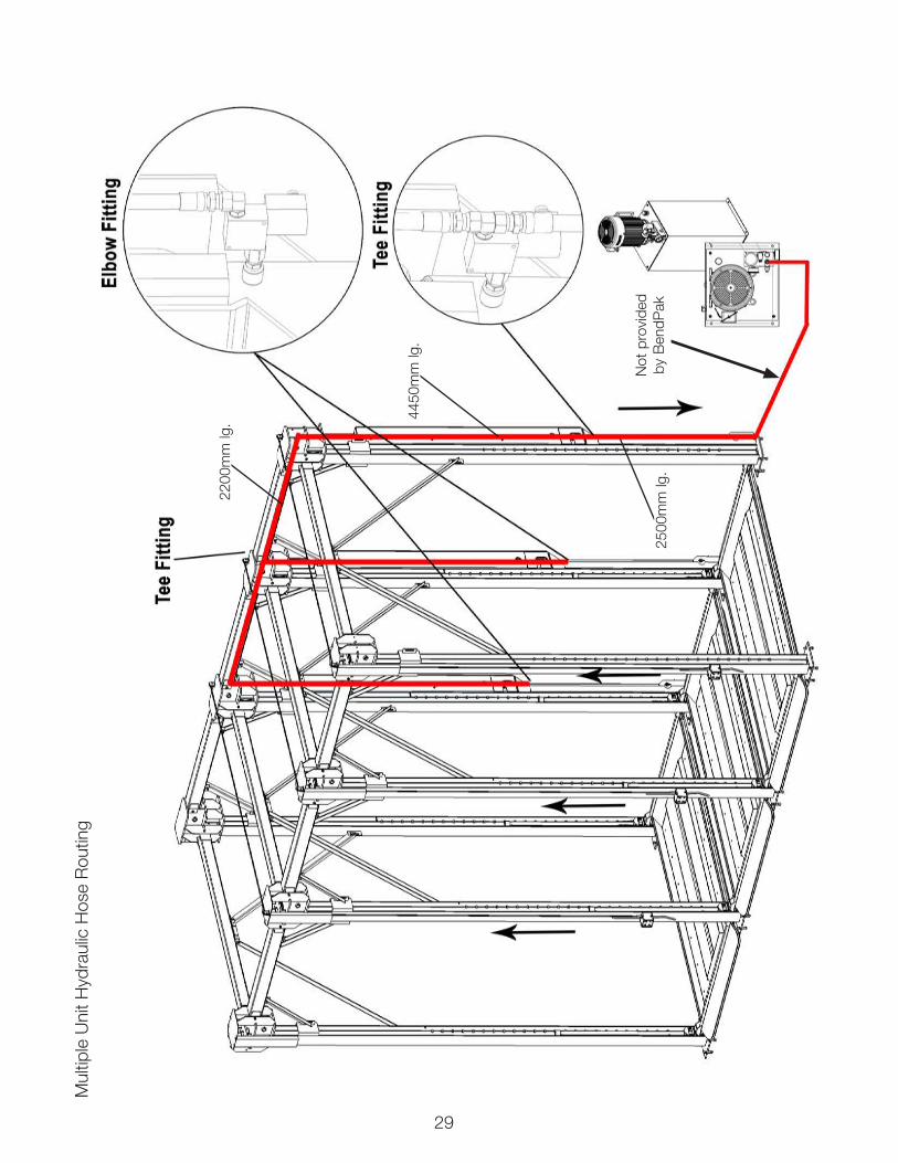
For a Multiple Unit installation - 1. Locate the hydraulic fittings and solenoid valves.
2. Connect the Hydraulic Hose, 90° ORB x JIC fitting, straight ORB reducing fitting and the power unit solenoid valve to the ports in the Power Unit. DO NOT USE TEFLON TAPE on the JIC flared end. (See Fig 8.1)
DANGER!DO NOT PERFORM ANY MAINTENANCE OR
INSTALLATION OF ANY COMPONENTS WITHOUT FIRST ENSURING THAT ELECTRICAL POWER HAS BEEN DISCONNECTED AT THE SOURCE OR PANEL
AND CANNOT BE RE-ENERGIZED UNTIL ALL MAINTENANCE AND/OR INSTALLATION
PROCEDURES ARE COMPLETED.
DANGER !ALL WIRING MUST BE PERFORMED
BY A LICENSED ELECTRICIAN.
DANGER!RISK OF EXPLOSION! THIS EQUIPMENT HAS INTERNAL ARCING OR PARTS THAT MAY SPARK AND SHOULD NOT BE EXPOSED TO FLAMMABLE VAPORS. MOTOR SHOULD NOT BE LOCATED IN A RECESSED AREA OR
BELOW FLOOR LEVEL. NEVER EXPOSE MOTOR TO RAIN OR OTHER DAMP ENVIRONMENTS. DAMAGE TO MOTOR CAUSED BY WATER IS NOT COVERED UNDER
WARRANTY.
WARNING!DO NOT RUN POWER UNIT WITHOUT OIL. DAMAGE TO
POWER UNIT PUMP CAN OCCUR. THE POWER UNIT MUST BE KEPT DRY. DAMAGE TO POWER UNIT CAUSED BY
WATER OR OTHER LIQUIDS SUCH AS DETERGENTS, ACID ETC., IS NOT COVERED UNDER WARRANTY.
OPERATE LIFT ONLY BETWEEN TEMPERATURES OF 41 °- 104° F. IMPROPER ELECTRICAL HOOK-UP CAN
DAMAGE MOTOR AND WILL NOT BE COVERED UNDER WARRANTY. MOTOR CAN NOT RUN ON 50HZ WITHOUT A
PHYSICAL CHANGE IN THE MOTOR.
USE A SEPARATE CIRCUIT BREAKER FOR EACH POWER UNIT. PROTECT EACH CIRCUIT WITH TIME DELAY FUSE
OR CIRCUIT BREAKER.
FOR 208-230 VOLT, SINGLE PHASE, USE A 25 AMP FUSE.FOR 208-230 VOLT, THREE PHASE, USE A 20 AMP FUSE.FOR 380-440 VOLT, THREE PHASE, USE A 15 AMP FUSE.
Fig 7.1
Fig 8.1
M4 Button Screws
Power Unit
Solenoid Valve
Straight ORB reducing fitting
90° ORB x JIC fitting

27
3. Connect the straight NPT fitting, straight ORB x NPT fitting, cylinder solenoid valve and 90° ORB x JIC fitting to the upper cylinder port. On the pipe thread (NPT) side of the Fitting it is recommended to use Teflon tape or pipe sealer. DO NOT USE TEFLON TAPE on the JIC flared end. (See Fig 8.2)
For a Single Unit installation -1. Attach the electrical box and power unit adapter plate to the Power Post using the provided M8 hardware as shown in Fig 8.3.
2. Connect the Hydraulic Hose and 90° ORB x JIC fitting to the port in the Power Unit. DO NOT USE TEFLON TAPE on the JIC flared end. (See Fig 8.4)
3. Connect the 90° NPT x JIC fitting to the upper cylinder port. On the pipe thread (NPT) side of the Fitting it is recom-mended to use Teflon tape or pipe sealer. DO NOT USE TEFLON TAPE on the JIC flared end. (See Fig 8.5)
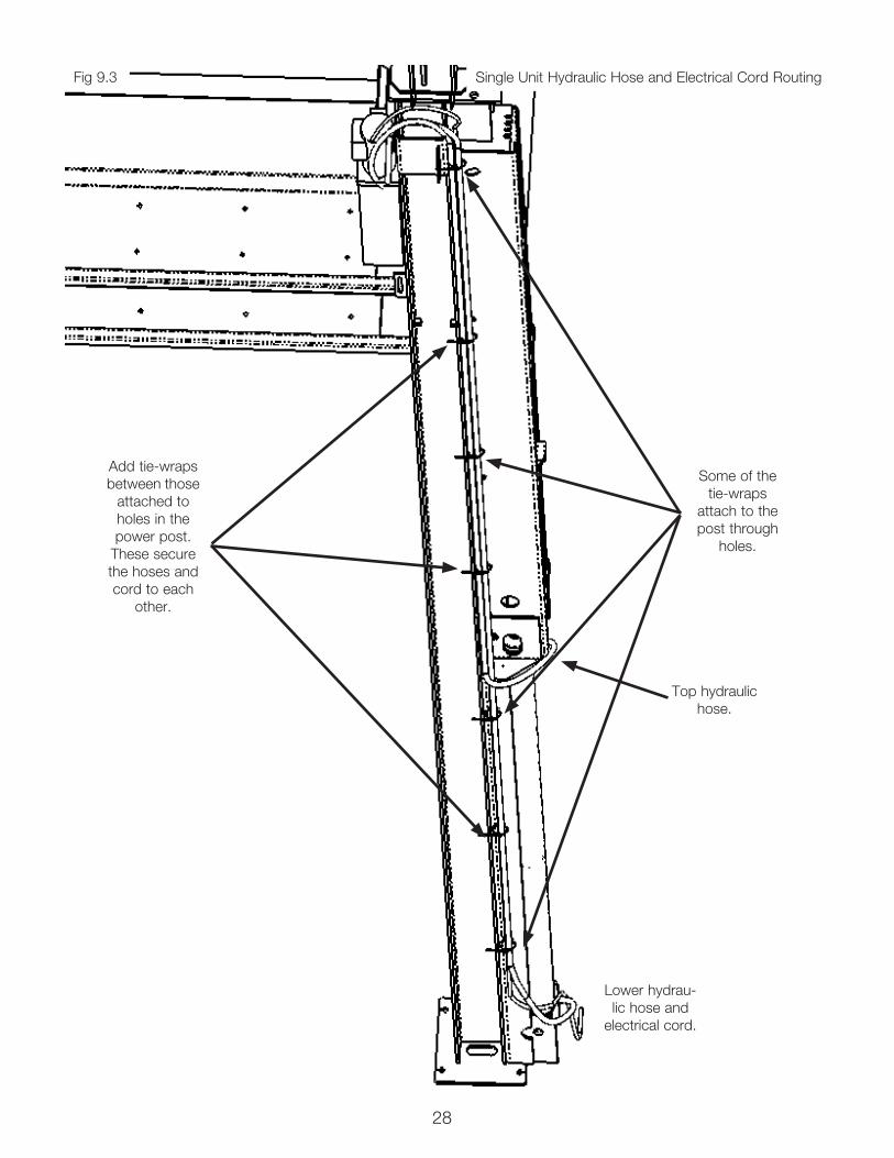
STEP 9(Hydraulic Hose Routing)
For a Multiple Unit installation - 1. See Fig 9.3.
For a Single Unit installation - 1. Route the hydraulic hose from the bottom of the cylin-der with the electrical cord. These are routed up the Power Post and secured with tie-wraps. (See Fig 9.1)
2. Join the top hydraulic hose with the routing of the bottom hose and electrical cord near the top of the cylin-der.
3. The tie-wraps securing the hoses and electrical cord alternate between being attached to holes in the post and simply securing them to each other. (See Fig 9.2)
4. At the power unit, the fittings must be angled to allow the hoses to route correctly toward the power post.
Fig 8.2
Fig 8.4
Fig 8.3
Fig 8.5
Fig 9.1
Cylinder Unit Solenoid Valve
Straight NPT Fitting
90° NPT x JIC Fitting
Straight ORB fitting
90° ORB x JIC fitting
Power Unit Adapter Plate
Electrical Box
90° ORB x JIC fitting
M8 NutM8 Bolt
Washer
Fig 9.2
Some of the tie-wraps
attach to the post through
holes.
Add tie-wraps between those
attached to holes in the power post.
These secure the hoses and cord to each
other.
28
Single Unit Hydraulic Hose and Electrical Cord Routing
Some of the tie-wraps
attach to the post through
holes.
Add tie-wraps between those
attached to holes in the power post.
These secure the hoses and cord to each
other.
Lower hydrau-lic hose and
electrical cord.
Top hydraulic hose.
Fig 9.3
29
Not
pro
vide
d by
Ben
dPak
4450
mm
lg.
2500
mm
lg.
2200
mm
lg.
Mul
tiple
Uni
t Hyd
raul
ic H
ose
Rou
ting

30
STEP 10(Lift Start Up / Final Adjustments)
1. On PL-14000 models make sure the Power Unit reser-voir is full with 6.5 gallons of 10-WT hydraulic oil or Dexron automatic transmission fluid. For PL-18000 models use 11.5 gallons.
2. Spray the inside of the Sheave Pullbox Glide Channel where the Sheave Pullbox glides with a light spray-oil.
3. Before proceeding, make sure all cables are properly positioned within the grooves of ALL sheaves. Make sure all Cable Sheave Pin Fasteners are secure.
4. Test the Power Unit by turning the key switch to “ON” pressing the “RAISE” push button on the Control Panel. If the motor sounds like it is operating properly, raise the lift and check all hose connections for leaks. If the motor gets hot or sounds peculiar, stop and check all electrical connec-tions.
5. Check to make sure that all Cable Break Safety locks are cleared and free. (See Fig. 10.1)
6. Continue pressing the “RAISE” button until the cables are taut and the lift starts to move.
7. Raise lift until the cylinder is fully retracted and the lift stops. Adjust each cable so that each corner of the Top Ramp Weldment rests at the same height above the ground. It may be necessary to tighten or loosen each cable nut to reach the proper height. The cable nuts must be tightened until there is at least 1” of threading protruding from the top of the nut. (See Fig. 10.2)
Fig 10.1
DANGER!VISUALLY CONFIRM THAT THE PRIMARY SAFETY
ON THE BACK OF THE POWER POST IS ENGAGED BEFORE ENTERING WORK AREA. SUSPENSION COMPONENTS ON THIS LIFT ARE INTENDED TO
RAISE AND LOWER LIFT ONLY AND ARE NOT MEANT TO BE LOAD HOLDING DEVICES. REMAIN CLEAR
OF ELEVATED LIFT UNLESS VISUAL CONFIRMATION IS MADE THAT THE PRIMARY SAFETY IS FULLY
ENGAGED. REFER TO INSTALLATION / OPERATION MANUAL FOR PROPER SAFETY LOCK PROCEDURES
AND / OR FURTHER INSTRUCTION.
Fig 10.2
1”/25mm

31
STEP 11(Bleeding the Cylinder)
1. Lift must be fully lowered before changing or adding fluid.
2. Raise and lower lift six times. The cylinder is self-bleed-ing. After bleeding system, fluid level in Power Unit reservoir may be low. Add more fluid if necessary to raise lift to full height. It is only necessary to add fluid to raise lift to full height.
3. To pressure test, raise lift to full rise and run motor for approximately 3-seconds after lift stops. This will put pres-sure on the hydraulic system. Stop and check all fittings and hose connections. Tighten or reseal if required.
POST-INSTALLATION CHECKLIST• Posts Properly Shimmed And Stable• Anchor Bolts Tightened• Safety / Sheave Pins Properly Attached• Electric Power Supply Confirmed• Cables Adjusted Properly• Safety Locks Functioning Properly• Check For Hydraulic Leaks• Oil Level• Lubrication of Critical Components• Check For Overhead Obstructions• Electrical cords and hydraulic hoses tied off and secure• Ramps Level• All Screws, Bolts, and Pins Secured• Surrounding Area Clean• Operation, Maintenance and Safety Manuals on Site
STEP 12(Operation)
To Raise Lift:
1. Position vehicle tires in the center of the lowest ramp.
2. Set parking brake.
3. Before raising vehicle, be sure all personnel are clear of the lift and surrounding area. Pay careful attention to over-head clearances.
4. Raise the lift to the desired height by pressing the RAISE push button on the Control Panel.
5. After vehicle is raised to the desired height, lower the lift until the primary safety engages. Do not allow cables to become slack. ALWAYS ENSURE THE SAFETY LOCK IS ENGAGED before entering work area.
To Lower Lift:
1. Before lowering vehicle, be sure all personnel are clear of the lift and surrounding area. Pay careful attention to overhead clearances. Ensure all tools and equipment have been cleared from under the lift.
2. Raise the lift off of the Safety Lock by pressing the RAISE push button on the Control Panel. Make sure you raise the lift by at least 2 inches to allow adequate clearance for the lock to clear.
3. Pull the Safety Handle towards the front of the lift.
4. Press the LOWER push button and HOLD.
5. Hold the LOWER push button until the lift has descend-ed completely.
WEEKLY MAINTENANCE
1. Lubricate all sheaves with general purpose spray-oil.
2. Check all cable connections, bolts, and pins to ensure proper mounting.
3. Lubricate Safety Lock pivot points with general pur-pose spray-oil.
MONTHLY MAINTENANCE
1. Check Safety Locks to ensure they are in good oper-ating condition.
2. Check all cables for excessive signs of wear.
3. Make a visual inspection of ALL MOVING PARTS and check for excessive signs of wear.
4. Replace ALL FAULTY PARTS before lift is put back into operation.
• NEVER EXCEED THE RATED CAPACITY of lift.• DO NOT USE LIFT if any component is found to be
defective or worn.• NEVER OPERATE LIFT with any person or equip-
ment below.• ALWAYS STAND CLEAR of lift when lowering or
raising.• ALWAYS ENSURE SAFETY LOCK IS ENGAGED
before entering work area.• NEVER LEAVE LIFT IN ELEVATED CONDITION
unless safety lock is engaged.
32
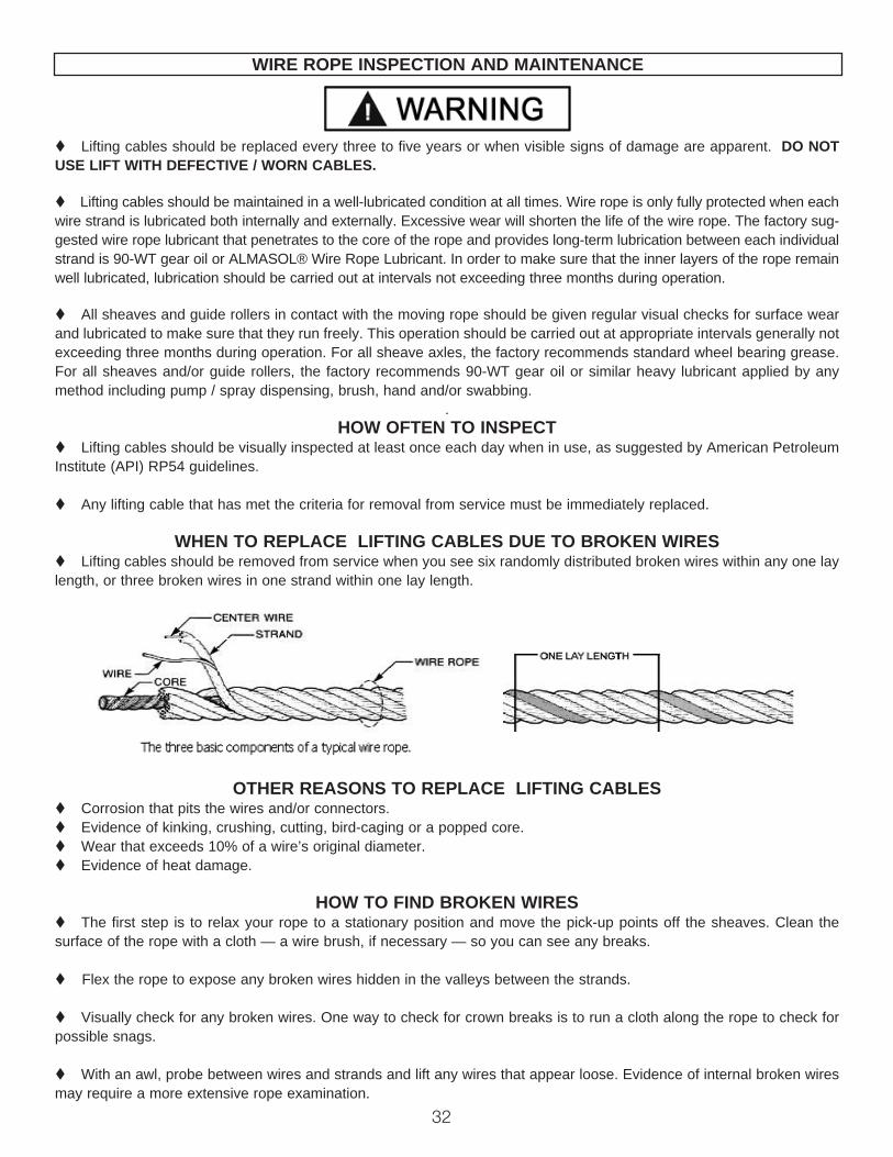
t Lifting cables should be replaced every three to five years or when visible signs of damage are apparent. DO NOT USE LIFT WITH DEFECTIVE / WORN CABLES.
t Lifting cables should be maintained in a well-lubricated condition at all times. Wire rope is only fully protected when each wire strand is lubricated both internally and externally. Excessive wear will shorten the life of the wire rope. The factory sug-gested wire rope lubricant that penetrates to the core of the rope and provides long-term lubrication between each individual strand is 90-WT gear oil or ALMASOL® Wire Rope Lubricant. In order to make sure that the inner layers of the rope remain well lubricated, lubrication should be carried out at intervals not exceeding three months during operation. t All sheaves and guide rollers in contact with the moving rope should be given regular visual checks for surface wear and lubricated to make sure that they run freely. This operation should be carried out at appropriate intervals generally not exceeding three months during operation. For all sheave axles, the factory recommends standard wheel bearing grease. For all sheaves and/or guide rollers, the factory recommends 90-WT gear oil or similar heavy lubricant applied by any method including pump / spray dispensing, brush, hand and/or swabbing.
.HOW OFTEN TO INSPECT
t Lifting cables should be visually inspected at least once each day when in use, as suggested by American Petroleum Institute (API) RP54 guidelines.
t Any lifting cable that has met the criteria for removal from service must be immediately replaced.
WHEN TO REPLACE LIFTING CABLES DUE TO BROKEN WIRESt Lifting cables should be removed from service when you see six randomly distributed broken wires within any one lay length, or three broken wires in one strand within one lay length.
OTHER REASONS TO REPLACE LIFTING CABLESt Corrosion that pits the wires and/or connectors.t Evidence of kinking, crushing, cutting, bird-caging or a popped core.t Wear that exceeds 10% of a wire’s original diameter.t Evidence of heat damage.
HOW TO FIND BROKEN WIRESt The first step is to relax your rope to a stationary position and move the pick-up points off the sheaves. Clean the surface of the rope with a cloth — a wire brush, if necessary — so you can see any breaks.
t Flex the rope to expose any broken wires hidden in the valleys between the strands. t Visually check for any broken wires. One way to check for crown breaks is to run a cloth along the rope to check for possible snags. t With an awl, probe between wires and strands and lift any wires that appear loose. Evidence of internal broken wires may require a more extensive rope examination.
WIRE ROPE INSPECTION AND MAINTENANCE
33
Safe Lift OperationAutomotive and truck lifts are critical to the operation and profitability of your business. The safe use of this and other lifts in your shop is critical in preventing employee injuries and damage to customer’s vehicles. By operating lifts safely you can ensure that your shop is profitable, productive and safe. Safe operation of automotive lifts requires that only trained employees should be allowed to use the lift.
TRAINING SHOULD INCLUDE, BUT NOT LIMITED TO:t Proper positioning of the vehicle on the runway. (See manufacturers minimize wheel base loading requirements.)
t Use of the operating controls.
t Understanding the lift capacity.
t Proper use of jack stands or other load supporting devices.
t Proper use, understanding and visual identification of safety lock devices and their operation.
t Reviewing the safety rules.
t Proper housekeeping procedures (lift area should be free of grease, oil, tools, equipment, trash, and other debris)
t A daily inspection of the lift should be completed prior to its use. Safety devices, operating controls, lift arms and other critical parts should be inspected prior to using the lift.
t All maintenance and repairs of the lift should be completed by following the manufacturer’s requirements. Lift repair parts should meet or exceed OEM specifications. Repairs should only be completed by a qualified lift technician.
t The vehicle manufacturer’s recommendations should be used for spotting and lifting the vehicle.
LIFT OPERATION SAFETY
t It is important that you know the load limit. Be careful that you do not overload the lift . If you are unsure what the load limit is, check the data plate found on one of the lift columns or contact the manufacturer.
t The center of gravity should be followed closely to what the manufacturer recommends.
t Always make sure you have proper overhead clearance. Additionally, check that attachments, (vehicle signs, campers, antennas, etc.) are not in the way.
t Be sure that prior to the vehicle being raised, the doors, trunk, and hood are closed securely
t Prior to being raised, make sure there is no one standing closer than six feet from the lift
t After positioning the vehicle on the lift runways, set the emergency brake, make sure the ignition is off, the doors are closed, overhead obstructions are cleared, and the transmission is in neutral.
t Double check that the automatic chock devices are in position and then when the lift is raised, observe the chocks t Put pads or adapters in the right position under the contact points that have been recommended
t The lift should be raised just until the vehicle’s wheels are about one foot off the ground. If contact with the vehicle is uneven or it appears that the vehicle is not sitting secure, carefully lower the lift and readjust.
t Always consider potential problems that might cause a vehicle to slip, i.e., heavy cargo, undercoating, etc.
t Pay attention when walking under a vehicle that is up on the hydraulic lift.

34
t DO NOT leave the controls while the lift is still in motion.
t DO NOT stand directly in front of the vehicle or in the bay when vehicle is being loaded or driven into position.
t DO NOT Go near vehicle or attempt to work on the vehicle when being raised or lowered.
t REMAIN CLEAR of lift when raising or lowering vehicle.
t DO NOT rock the vehicle while on the lift or remove any heavy component from vehicle that may cause excessive weight shift.
t DO NOT lower the vehicle until people, materials, and tools are clear
t ALWAYS ENSURE that the safeties are engaged and lowered on to the safety ladders before any attempt is made to work on or near vehicle.
t Some vehicle maintenance and repair activities may cause the vehicle to shift. Follow the manufacturer’s guidelines when performing these operations. The use of jack stands or alternate lift points may be required when completing some repairs.
t READ AND UNDERSTAND all safety warning procedures before operating lift.
t KEEP HANDS AND FEET CLEAR. Remove hands and feet from any moving parts. Keep feet clear of lift when lowering. Avoid pinch points.
t ONLY TRAINED OPERATORS should operate this lift. All non-trained personnel should be kept away from work area. Never let non-trained personnel come in contact with, or operate lift.
t USE LIFT CORRECTLY. Use lift in the proper manner. Never use lifting adapters other than what is approved by the manufacturer.
t DO NOT override self-closing lift controls.
t CLEAR AREA if vehicle is on danger of falling.
t STAY ALERT. Watch what you are doing. Use common sense. Be aware.
t CHECK FOR DAMAGED PARTS. Check for alignment of moving parts, breakage of parts or any condition that may affect its operation. Do not use lift if any component is broken or damaged.
t NEVER remove safety related components from the lift. Do not use lift if safety related components are damaged or missing.
t When the lift is being lowered, make sure everyone is standing at least six feet away.
t Be sure there are no jacks, tools, equipment, left under the lift before lowering.
t Always lower the vehicle down slowly and smoothly.
Safe Lift Operation (Cont’d)

35

36

37
LIFT WILL NOT RAISE
POSSIBLE CAUSE1. Air in oil, (1,2,8,12)2. Cylinder binding, (9)3. Cylinder leaks internally, (9)4. Motor run backward under pressure, (11)5. Lowering valve leaks, (3,4,6,10,11)6. Motor runs backwards, (7,13,11)7. Pump damaged, (10,11)8. Pump won’t prime, (1,8,12,13,3,10,11)9. Relief valve leaks, (10,11)10. Voltage to motor incorrect, (7,13,11)
REMEDY INSTRUCTION1. Check for proper oil level. . . . . . . . . . . . . . . . . . . . . . . . . . The oil level should be up to the bleed screw in the reservoir with the lift all the way down.
2. Bleed cylinders. . . . . . . . . . . . . . . . . . . . . . . . . . . . . . . . . . See Installation Manual
3. Flush release valve to get rid of. . . . . . . . . . . . . . . . . . . . . Hold release handle down and start unit allowing possible contamination it to run for 15 seconds.
4. Dirty oil. . . . . . . . . . . . . . . . . . . . . . . . . . . . .. . . . . . . . . . . . Replace oil with clean Dexron ATF.
5. Tighten all fasteners. . . . . . . . . . . . . . . . . . . . . . . . . . . . . . . Tighten fasteners to recommended torques.
6. Check for free movement of release. . . . . . . . . . . . . . . . . . . If handle does not move freely, replace bracket or handle assembly. 7. Check if motor is wired correctly. . . . . . . . . . . . . . . . . . . . . . .Compare wiring of motor to electrical diagram on drawing.
8. Oil seal damaged or cocked . . . . . . . . . . . . . . . . . . . . . . . . Replace oil seal around pump shaft.
9. See Installation Manual . . . . . . . . . . . . . . . . . . . . . . . . . . . . Contact BendPak Customer Support.
10. Replace with new part . . . . . . . . . . . . . . . . . . . . . . . . . . . . . Replace with new part.
11. Return unit for repair . . . . . . . . . . . . . . . . . . . . . . . . . . . . . . Return unit for repair.
12. Inlet screen clogged . . . . . . . . . . . . . . . . . . . . . . . . . . . . . . Clean inlet screen or replace.
13. Check wall outlet voltages and wiring . . . . . . . . . . . . . . . . . Make sure unit and wall outlet are wired properly.

38
MOTOR WILL NOT RUN
POSSIBLE CAUSE1. Fuse blown, (5,2,1,3,4)2. Limit switch burned out, (1,2,3,4)3. Microswitch burned out, (1,2,3,4)4. Motor burned out, (1,2,3,4,6)5. Voltage to motor incorrect, (2,1,8)
REMEDY INSTRUCTION1. Check for correct voltage . . . . . . . . . . . . . . . . . . . . . . . . . . .Compare supply voltage with voltage on motor name tag. Check that the wire is sized correctly. N.E.C. table 310-12 requires AWG 10 for 25 Amps. 2. Check motor is wired correctly . . . . . . . . . . . . . . . . . . . . . . .Compare wiring of motor to electrical diagram on drawing.
3. Don’t use extension cords . . . . . . . . . . . . . . . . . . . . . . . . . . According to N.E.C. : “ The size of the conductors… should be such that the voltage drop would not exceed 3% to the farthest outlet for power…” Do not run motor at 115 VAC – damage to the motor will occur.
4. Replace with new part . . . . . . . . . . . . . . . . . . . . . . . . . . . . .Replace with new part.
5. Reset circuit breaker/fuse . . . . . . . . . . . . . . . . . . . . . . . . . .Reset circuit breaker/fuse.
6. Return unit for repair . . . . . . . . . . . . . . . . . . . . . . . . . . . . . Return unit for repair.
7. See Installation Manual . . . . . . . . . . . . . . . . . . . . . . . . . . . .See Installation Manual.
8. Check wall outlet voltage and wiring . . . . . . . . . . . . . . . . . . Make sure unit and wall outlet is wired properly. Motor must run at 208/230 VAC.
LIFT LOWERS SLOWLY OR NOT AT ALL
POSSIBLE CAUSE1. Cylinders binding, (1)2. Release valve clogged, (5,4,2,3)3. Pressure fitting too long, (6)
REMEDY INSTRUCTION1. See Installation Manual . . . . . . . . . . . . . . . . . . . . . . . . . . . Contact BendPak Customer Support.
2. Replace with new part . . . . . . . . . . . . . . . . . . . . . . . . . . . . Replace with new part.
3. Return for repair . . . . . . . . . . . . . . . . . . . . . . . . . . . . . . . . . Return for repair.
4. Check oil. . . . . . . . . . . . . . . . . . . . . . . . . . . . . . . . . . . . . . Use clean 10-WT hydraulic oil or Dexron automatic transmission fluid only. If ATF is contaminated, replace with clean ATF and clean entire system.
5. Clean release valve . . . . . . . . . . . . . . . . . . . . . . . . . . . . . . . . Wash release valve in solvent and blow out with air.
6. Replace fitting with short thread lead . . . . . . . . . . . . . . . . . . . Replace fitting with short thread lead.

39
WILL NOT RAISE LOADED LIFT
POSSIBLE CAUSE1. Air in oil, (1,2,3,4)2. Cylinder binding, (5)3. Cylinder leaks internally, (5)4. Lift overloaded, (6,5)5. Lowering valve leaks, (7,8,1,5,9)6. Motor runs backwards, (10,12,9)7. Pump damaged, (5,9)8. Pump won’t prime, (1,2,3,4,5,11,9)9. Relief valve leaks, (8,5,9)10. Voltage to motor incorrect, (10,12,5)
REMEDY INSTRUCTION1. Check oil level . . . . . . . . . . . . . . . . . . . . . . . . . . . . . . . . . . The oil level should be up to the bleed screw in the reservoir with the lift all the way down.
2. Check/Tighten inlet tubes . . . . . . . . . . . . . . . . . . . . . . . . . . Replace inlet hose assembly.
3. Oil seal damaged or cocked . . . . . . . . . . . . . . . . . . . . . . . . Replace oil seal and install.
4. Bleed cylinders . . . . . . . . . . . . . . . . . . . . . . . . . . . . . . . . . . See Installation Manual.
5. See Installation Manual . . . . . . . . . . . . . . . . . . . . . . . . . . . . Contact BendPak Customer Support.
6. Check vehicle weight . . . . . . . . . . . . . . . . . . . . . . . . . . . . . Compare weight of vehicle to weight limit of the lift.
7. Flush release valve . . . . . . . . . . . . . . . . . . . . . . . . . . . . . Hold release handle down and start unit allowing it to run for 15 seconds.
8. Replace with new part . . . . . . . . . . . . . . . . . . . . . . . . . . . . . Replace with new part.
9. Return unit for repair . . . . . . . . . . . . . . . . . . . . . . . . . . . . . . Return unit for repair.
10. Check motor is wired correctly . . . . . . . . . . . . . . . . . . . . . . . Compare wiring of motor to electrical diagram on power unit drawing.
11. Inlet screen clogged . . . . . . . . . . . . . . . . . . . . . . . . . . . . . . Clean inlet screen or replace.
12. Check wall outlet voltage and wiring . . . . . . . . . . . . . . . . . . Make sure unit and wall outlet is wired properly.
IMPORTANTIf vehicle becomes stranded in the air, follow all operation instructions as shown on pages 31 and 38. If after observing that all mechanical locks are released and the lift still fails move following all standard operating procedures, immediately stop using the lift and contact factory or factory approved service center for further instructions.

40
LIFT WILL NOT STAY UPPOSSIBLE CAUSE1. Air in oil, (1,2,3)2. Check valve leaks, (6)3. Cylinders leak internally, (7)4. Lowering valve leaks, (4,5,1,7,6)5. Leaking fittings, (8)
REMEDY INSTRUCTION1. Check oil level . . . . . . . . . . . . . . . . . . . . . . . . . . . . . . . . . . . The oil level should be up to the bleed screw in the reservoir with the lift all the way down.
2. Oil seal damaged and cocked . . . . . . . . . . . . . . . . . . . . . . . . Replace oil seal around pump shaft.
3. Bleed cylinder . . . . . . . . . . . . . . . . . . . . . . . . . . . . . . . . . . . . Refer to Installation Manual.
4. Flush release valve . . . . . . . . . . . . . . . . . . . . . . . . . . . . . . . . Hold release handle down and start unit allowing it to run for 15 seconds.
5. Replace with new valve . . . . . . . . . . . . . . . . . . . . . . . . . . . . . Replace with new valve.
6. Return unit for repair . . . . . . . . . . . . . . . . . . . . . . . . . . . . . . . Return unit for repair.
7. See Installation Manual . . . . . . . . . . . . . . . . . . . . . . . . . . . . . Contact BendPak Customer Support.
8. Check complete hydraulic system for leaks. . . . . . . . . . . . . . Tighten all hydraulic fittings and inspect all hoses.
VALUES ARE STATED IN FOOT POUNDS (ft-lb)
SAE 0-1-2 SAE Grade 5 SAE Grade 8 SOCKET HEAD CAP SCREW
CLASS 4.8 CLASS 8.8 CLASS 10.9 CLASS 12.9
Bolt Size (SAE)
Bolt Size (Metric)
1/4-20 M6 x 1.0 6 10 14 13
5/16-18 M8 x 1.25 12 19 29 31.4
3/8-16 M10 x 1.50 20 33 47 62
7/16-14 32 54 78
1/2-13 M12 x 1.75 47 78 119 108
9/16-12 M14 x 2.00 69 114 169 173
5/8-11 M16 x 2.00 96 154 230 269
3/4-10 M18 x 2.50 155 257 380 372
7/8-9 M22 x 2.50 206 382 600 716
3/4 Anchor Bolts 75 MIN 110 MAX
Torque Recommendations

41
Grease Port / Lubrication Locations
Lubricate Once A Week

42
MAINTENANCE RECORDS
____________________________________________________________________
____________________________________________________________________
____________________________________________________________________
____________________________________________________________________
____________________________________________________________________
____________________________________________________________________
____________________________________________________________________
____________________________________________________________________
____________________________________________________________________
____________________________________________________________________
____________________________________________________________________
____________________________________________________________________
____________________________________________________________________
____________________________________________________________________
____________________________________________________________________
____________________________________________________________________
____________________________________________________________________
____________________________________________________________________
____________________________________________________________________
____________________________________________________________________

43

44
2
1
3
.A
MM
NI ERA S
NOIS
NEMI
D :EZIS
:LAIRET
AM
GNI
WAR
D ELA
CS TO
N O
D
SI
GNI
WARD SIHT
NI DE
NIATN
OC
NOITA
MROF
NI EHT F
O YTREPORP EL
OS EHT Y
NA
TUOHTI
W ELOH
W A SA RO TRAP
NI N
OITCU
DORPER
FO
NOISSI
MREP NETTIR
W EHT SI
.DETIBIH
ORP06:1 :EL
ACS
3 FO 1 TEEHS
VER.
ON .
GW
DEZIS
:ELTIT
EM
AN
ETA
D
DEKCEH
C
NW
ARD
.RD
DO
OW
NO
MEL 546106039
AC ,
ALUAP
ATN
ASMT
4102/4 1/10
NOIT
CEJORP EL
GN
A DRIHT
A6320625
N
OITCU
DORP 00041-LP
C REV TFIL
GNI
GAK
CAP L
ANIF R
OF SN
OITCURTS
NI G
NIPPIHS EES.1
DEIFICEPS
ESIWREHT
OSSELNU:ET
ON
☺L
AITNEDIF
NO
CD
NA
YRATEIRP
ORP
.C
NIK
APDNEB
.CNI
KAPD
NEB
ON
METIREB
MUN TR
APN
OITPIRCSE
DYT
QVER
17725425
ERUTCURTSREPUS TFIL 00041-LP
1A
22820525
XOB STR
AP 00041-LP1
A3
505205528 x 0.5
Ø YLBMESS
A RED
NILYC LLUP
1A
NOISIVER
VERN
OITPIRCSE
DET
AD
YB DETI
DE#
OCE
A3010625
MORF
DEVIRED ,ES
AELER N
OITCU
DORP
4102/41/10MT
93600
--- ---

45
4
01
21
1
6
3
7
11
29
8
315
.A
MM
NI ERA S
NOIS
NEMI
D :EZIS
:LAIRET
AM
GNI
WAR
D ELA
CS TO
N O
D
SI
GNI
WARD SIHT
NI DE
NIATN
OC
NOITA
MROF
NI EHT F
O YTREPORP EL
OS EHT Y
NA
TUOHTI
W ELOH
W A SA RO TRAP
NI N
OITCU
DORPER
FO
NOISSI
MREP NETTIR
W EHT SI
.DETIBIH
ORP06:1 :EL
ACS
1 FO 1 TEEHS
VER.
ON .
GW
DEZIS
:ELTIT
EM
AN
ETA
D
DEKCEH
C
NW
ARD
.RD
DO
OW
NO
MEL 546106039
AC ,
ALUAP
ATN
ASMT
3102/22/20
NOIT
CEJORP EL
GN
A DRIHT
A7725425
TFIL 00041-LPERUT
CURTSREPUS
GNI
GAK
CAP L
ANIF R
OF SN
OITCURTS
NI G
NIPPIHS EES.1
DEIFICEPS
ESIWREHT
OSSELNU:ET
ON
☺L
AITNEDIF
NO
CD
NA
YRATEIRP
ORP
.C
NIK
APDNEB
.CNI
KAPD
NEBYLB
MESSA TXE
N6320625
METIO
N TR
APREB
MUN
NOITPIR
CSED
YTQ
VER1
4280065T
NEM
DLEW TS
OP REW
OP 00041-LP1
A2
3280065T
NEM
DLEW TS
OP LORT
NO
C TN
ORF 00041 -LP1
A3
2465125YLB
MESSA X
OBLLUP 00041-LP1
A4
7465125YLB
MESSA YTEF
AS KAERB ELB
AC 00081/00041-LP
4A
55465125
YLBMESS
A D
OR G
NITFIL PM
AR 00041-LP4
A6
5180065T
NEM
DLEW P
MAR
MOTT
OB 00081/00041-LP1
A7
2070265T
NEM
DLEW P
MAR P
OT 00041-LP1
A8
9750065T
NEM
DLEW EBUT SS
ORC
GN
OL 00081/00041-LP1
B9
4850065T
NORF TR
OHS ,TNE
MDLE
W EBUT SSOR
C 00081/00041-LP1
B01
8370065R
AER TROHS ,T
NEM
DLEW EBUT SS
ORC 00081 /00041-LP
1A
116731275
ELG
NA T
NORF 00081/00041-LP
2C
215731275
ELG
NA R
AER 00081/00041-LP2
C31
7731275EL
GN
A EDIS 00081/00041-LP
2C
NOISIVER
VERN
OITPIRCSE
DET
AD
YB DETI
DE#
OCE
A8735425
MORF
DEVIRED ,ES
AELER N
OITCU
DORP
4102/31/10MT
93600
--- ---

46
ALIATED8:
1ELA
CS
7
6
5
8
A
4
2
1
9
3
.A
MM
NI ERA S
NOIS
NEMI
D :EZIS
:LAIRET
AM
GNI
WAR
D ELA
CS TO
N O
D
SI
GNI
WARD SIHT
NI DE
NIATN
OC
NOITA
MROF
NI EHT F
O YTREPORP EL
OS EHT Y
NA
TUOHTI
W ELOH
W A SA RO TRAP
NI N
OITCU
DORPER
FO
NOISSI
MREP NETTIR
W EHT SI
.DETIBIH
ORP05:1 :EL
ACS
1 FO 1 TEEHS
VER.
ON .
GW
DEZIS
:ELTIT
EM
AN
ETA
D
DEKCEH
C
NW
ARD
.RD
DO
OW
NO
MEL 546106039
AC ,
ALUAP
ATN
ASMT
4102/4 1/10
NOIT
CEJORP EL
GN
A DRIHT
A0255715
TUOES
OLC 00 041-LP
ERUTCURTSREPUS
GELC REV
GNI
GAK
CAP L
ANIF R
OF SN
OITCURTS
NI G
NIPPIHS EES.1
DEIFICEPS
ESIWREHT
OSSELNU:ET
ON
☺L
AITNEDIF
NO
CD
NA
YRATEIRP
ORP
.C
NIK
APDNEB
.CNI
KAPD
NEB
NOISIVER
VERN
OITPIRCSE
DET
AD
YB DETI
DE#
OCE
A5645715
MORF
DEVIRED ,ES
AELER N
OITCU
DORP
4102/41/10MT
93600
ON
METIREB
MUN TR
APN
OITPIRCSE
DYT
QVER
15280065
TNE
MDLE
W TSOP K
CAB TU
O ESOL
C 00041-LP1
--2
6280065T
NEM
DLEW TS
OP TN
ORF TUO ES
OLC 00041-LP
1A
39750065
TNE
MDLE
W EBUT SSOR
C G
NOL 00081/00041-LP
1B
47731275
ELG
NA E
DIS 00081/00041-LP2
C5
2435455T
ALF 81M REHS
AW
01--
60535455
LS 82 x 81M REHS
AW
8--
72025355
8.8 LC 5.2 x 81
M TUN
8--
89130355
8.8 LC 05 x 5.2 x 81
M BHH8
--9
8030355"7 x "4/3 B
A8
--
HTIW ESU R
OF6320625
--- ---
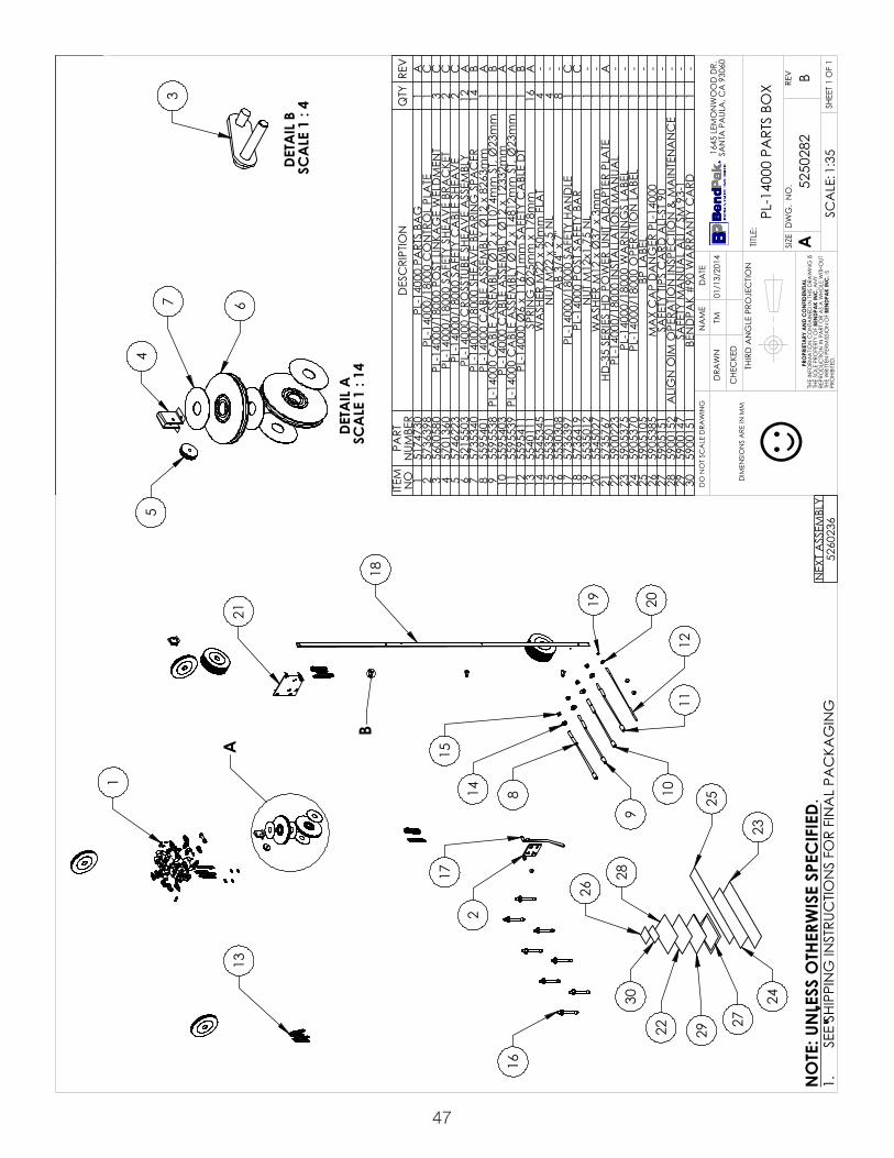
47
DIM
ENSI
ON
S A
RE IN
MM
☺
A
B
1
18
17
8
9
15
14
1110
12
2
2019
2113
16
23
252922 27
2830
26
24
DETA
IL A
SC
ALE
1 :
14
45
7 6
DETA
IL B
SC
ALE
1 :
43
NEX
T A
SSEM
BLY
5260
236
ITEM
N
OPA
RT
NUM
BER
DES
CRI
PTIO
NQ
TYRE
V1
5174
730
PL-1
4000
PA
RTS
BAG
1A
257
3639
8PL
-140
00/1
8000
CO
NTR
OL
PLA
TE1
C3
5600
580
PL-1
4000
/180
00 P
OST
LIN
KAG
E W
ELD
MEN
T3
C4
5701
360
PL-1
4000
/180
00 S
AFE
TY S
HEA
VE
BRA
CKE
T2
C5
5746
223
PL-1
4000
/180
00 S
AFE
TY C
ABL
E SH
EAV
E2
C6
5215
503
PL-1
4000
CRO
SSTU
BE S
HEA
VE
ASS
EMBL
Y12
A7
5735
340
PL-1
4000
/180
00 S
HEA
VE
BEA
RIN
G S
PAC
ER14
B8
5595
401
PL-1
4000
CA
BLE
ASS
EMBL
Y Ø
12 x
826
3mm
1A
955
9553
8PL
-140
00 C
ABL
E A
SSEM
BLY
Ø12
x 1
1074
mm
ST,
Ø23
mm
1B
1055
9540
3PL
-140
00 C
ABL
E A
SSEM
BLY
Ø12
x 1
2332
mm
1A
1155
9553
9PL
-140
00 C
ABL
E A
SSEM
BLY
Ø12
x 1
4812
mm
ST,
Ø23
mm
1A
1255
9541
1PL
-140
00 Ø
6 x
1167
1mm
SA
FETY
CA
BLE
DT
1B
1355
4011
1SP
RIN
G Ø
25m
m x
178
mm
16A
1455
4534
5W
ASH
ER M
22 x
50m
m F
LAT
4-
1555
3501
1N
UT M
22 x
2.5
NL
4-
1655
3030
8A
B 3/
4" x
7"
8-
1757
3639
7PL
-140
00/1
8000
SA
FETY
HA
ND
LE1
C18
5736
419
PL-1
4000
PO
ST S
AFE
TY B
AR
1C
1955
3501
2N
UT M
12x1
.75
NL
1-
2055
4502
7W
ASH
ER M
12 x
Ø37
x 3
mm
1-
2157
3576
7HD
-35
SERI
ES H
D P
OW
ER U
NIT
AD
APT
ER P
LATE
1A
2259
0022
3PL
-140
00/1
8000
INST
ALL
ATIO
N M
AN
UAL
1-
2359
0537
5PL
-140
00/1
8000
WA
RNIN
GS
LABE
L1
-24
5905
370
PL-1
4000
/180
00 O
PERA
TION
LA
BEL
1-
2559
0510
5BP
LA
BEL
1-
2659
0538
5M
AX
CA
P D
AN
GER
PL-
1400
01
-27
5905
151
SAFE
TY T
IPS
CA
RD A
LI-S
T 90
1-
2859
0015
2A
LIG
N O
IM O
PERA
TION
INSP
ECTIO
N &
MA
INTE
NA
NC
E1
-29
5900
147
SAFE
TY M
AN
UAL
ALI
/ S
M 9
3-1
1-
3059
0015
1BE
ND
PAK
#90
WA
RRA
NTY
CA
RD1
-
REV
ISIO
NRE
VD
ESC
RIPT
ION
DA
TEED
ITED
BY
ECO
#A
PRO
DUC
TION
REL
EASE
, DER
IVED
FRO
M 5
2501
1201
/13/
2014
TM00
639
BUP
DA
TED
BO
M R
EVIS
ION
S08
/29/
2014
TM00
668
SHE
ET 1
OF
1
REV
DW
G.
NO
.
ASIZETITLE
:
NA
ME
DA
TE
CHE
CKE
D
DRA
WN
B
1645
LEM
ON
WO
OD
DR.
SAN
TA P
AUL
A, C
A 9
3060
PRO
PRIE
TARY
AN
D C
ON
FIDE
NTIA
LTH
E IN
FORM
ATIO
N C
ON
TAIN
ED IN
THI
S D
RAW
ING
IS
THE
SOLE
PRO
PERT
Y O
F BE
NDP
AK
INC
. AN
Y RE
PRO
DUC
TION
IN P
ART
OR
AS
A W
HOLE
WITH
OUT
TH
E W
RITT
EN P
ERM
ISSI
ON
OF
BEN
DPA
K IN
C. I
S PR
OHI
BITE
D.
NO
TE: U
NLE
SS O
THER
WIS
E SP
ECIF
IED.
TM
5250
282
PL-1
4000
PA
RTS
BOX
01/1
3/20
14
DO
NO
T SC
ALE
DRA
WIN
G
1:35
SCA
LE:
THIR
D A
NG
LE P
ROJE
CTIO
N
SEE
SHIP
PIN
G IN
STRU
CTIO
NS
FOR
FIN
AL
PAC
KAG
ING
1.

48
2
1
3
NOISIVER
VERN
OITPIRCSE
DET
AD
YB DETI
DE#
OCE
A6810625
MROF
DEVIRED ,ES
AELER N
OITCU
DORP
4102/42/10MT
93600
.A
MM
NI ERA S
NOIS
NEMI
D :EZIS
:LAIRET
AM
GNI
WAR
D ELA
CS TO
N O
D
SI
GNI
WARD SIHT
NI DE
NIATN
OC
NOITA
MROF
NI EHT F
O YTREPORP EL
OS EHT Y
NA
TUOHTI
W ELOH
W A SA RO TRAP
NI N
OITCU
DORPER
FO
NOISSI
MREP NETTIR
W EHT SI
.DETIBIH
ORP06:1 :EL
ACS
3 FO 1 TEEHS
VER.
ON .
GW
DEZIS
:ELTIT
EM
AN
ETA
D
DEKCEH
C
NW
ARD
.RD
DO
OW
NO
MEL 546106039
AC ,
ALUAP
ATN
ASMT
4102/71/10
NOIT
CEJORP EL
GN
A DRIHT
A1910625
N
OITCU
DORP LX00041-LP
B REV TFIL
GNI
GAK
CAP L
ANIF R
OF SN
OITCURTS
NI G
NIPPIHS EES.1
DEIFICEPS
ESIWREHT
OSSELNU:ET
ON
☺L
AITNEDIF
NO
CD
NA
YRATEIRP
ORP
.C
NIK
APDNEB
.CNI
KAPD
NEB
ON
METIREB
MUN TR
APN
OITPIRCSE
DYT
QVER
16725425
ERUTCURTSREPUS TFIL LX00041-LP
1A
23820525
XOB STR
AP LX00041-LP1
A3
505205528 x 0.5
Ø YLBMESS
A RED
NILYC LLUP
1A
--- ---
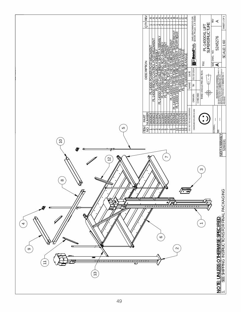
49
4
01
21
1
6
3
7
11
5
29
8
31
.A
MM
NI ERA S
NOIS
NEMI
D :EZIS
:LAIRET
AM
GNI
WAR
D ELA
CS TO
N O
D
SI
GNI
WARD SIHT
NI DE
NIATN
OC
NOITA
MROF
NI EHT F
O YTREPORP EL
OS EHT Y
NA
TUOHTI
W ELOH
W A SA RO TRAP
NI N
OITCU
DORPER
FO
NOISSI
MREP NETTIR
W EHT SI
.DETIBIH
ORP06:1 :EL
ACS
1 FO 1 TEEHS
VER.
ON .
GW
DEZIS
:ELTIT
EM
AN
ETA
D
DEKCEH
C
NW
ARD
.RD
DO
OW
NO
MEL 546106039
AC ,
ALUAP
ATN
ASMT
4102/22/10
NOIT
CEJORP EL
GN
A DRIHT
A6725425
TFIL LX00041-LPERUT
CURTSREPUS
GNI
GAK
CAP L
ANIF R
OF SN
OITCURTS
NI G
NIPPIHS EES.1
DEIFICEPS
ESIWREHT
OSSELNU:ET
ON
☺L
AITNEDIF
NO
CD
NA
YRATEIRP
ORP
.C
NIK
APDNEB
.CNI
KAPD
NEBYLB
M ESSA TXE
N1910625
METIO
N TR
APREB
MUN
NOITPIR
CSED
YTQ
VER1
4280065T
NEM
DLEW TS
OP REW
OP 00041-LP1
A2
3280065T
NEM
DLEW TS
OP LORT
NO
C TN
ORF 00041-LP1
A3
2465125YLB
MESSA X
OBLLUP 00041-LP1
A4
7465125YLB
MESSA YTEF
AS KAERB ELB
AC 00081/00041-LP
4A
55465125
YLBMESS
A D
OR G
NITFIL PM
AR 00041-LP4
A6
1280065T
NEM
DLEW P
MAR
MOTT
OB LX00041-LP1
A7
1380065T
NEM
DLEW P
MAR P
OT LX00041-LP1
A8
4970065T
NEM
DLEW EBUT SS
ORC
GN
OL LX0 0041-LP1
A9
4850065T
NORF TR
OHS ,TNE
MDLE
W EBUT SSOR
C 00081/00041-LP1
B01
8370065R
AER TROHS ,T
NEM
DLEW EBUT SS
ORC 00081/00041-LP
1A
116731275
ELG
NA T
NORF 00081/00041-LP
2C
215731275
ELG
NA R
AER 00081/00041-LP2
C31
6211275EL
GN
A EDIS LX00041-LP
2A
NOISIVER
VERN
OITPIRCSE
DET
AD
YB DETI
DE#
OCE
A4725425
MORF
DEVIRED ,ES
AELER N
OITCU
DORP
4102/22/10MT
93600
--- ---

50
ALIATED8:
1ELA
CS
7
6
5
8
A
4
2
1
9
3
.A
MM
NI ERA S
NOIS
NEMI
D :EZIS
:LAIRET
AM
GNI
WAR
D ELA
CS TO
N O
D
SI
GNI
WARD SIHT
NI DE
NIATN
OC
NOITA
MROF
NI EHT F
O YTREPORP EL
OS EHT Y
NA
TUOHTI
W ELOH
W A SA RO TRAP
NI N
OITCU
DORPER
FO
NOISSI
MREP NETTIR
W EHT SI
.DETIBIH
ORP05:1 :EL
ACS
1 FO 1 TEEHS
VER.
ON .
GW
DEZIS
:ELTIT
EM
AN
ETA
D
DEKCEH
C
NW
ARD
.RD
DO
OW
NO
MEL 546106039
AC ,
ALUAP
ATN
ASMT
4102/6 1/10
NOIT
CEJORP EL
GN
A DRIHT
A1255715
TUOES
OLC LX00041-LP
ERUTCURTSREPUS
GELB REV
GNI
GAK
CAP L
ANIF R
OF SN
OITCURTS
NI G
NIPPIHS EES.1
DEIFICEPS
ESIWREHT
OSSELNU:ET
ON
☺L
AITNEDIF
NO
CD
NA
YRATEIRP
ORP
.C
NIK
APDNEB
.CNI
KAPD
NEB
ON
METIREB
MUN TR
APN
OITPIRCSE
DYT
QVER
15280065
TNE
MDLE
W TSOP K
CAB TU
O ESOL
C 00041-LP1
A2
6280065T
NEM
DLEW TS
OP TN
ORF TUO ES
OLC 00041-LP
1A
34970065
TNE
MDLE
W EBUT SSOR
C G
NOL LX00041-LP
1A
46211275
ELG
NA E
DIS LX00041-LP2
A5
2435455T
ALF 81M REHS
AW
01--
60535455
LS 82 x 81M REHS
AW
8--
72025355
8.8 LC 5.2 x 81
M TUN
8--
89130355
8.8 LC 05 x 5.2 x 81
M BHH8
--9
8030355"7 x "4/3 B
A8
--
NOISIVER
VERN
OITPIRCSE
DET
AD
YB DETI
DE#
OCE
A5075715
MORF
DEVIRED ,ES
AELER N
OITCU
DORP
4102/61/10MT
93600
HTIW ESU R
OF1910625
--- ---

51
DIM
ENSI
ON
S A
RE IN
MM
☺
A
1
11
8
13
15
12
14 21
20
19
9
4
1817
5
10
16 2529
27
30 24 22
23
28
26
DETA
IL A
SC
ALE
1 :
18
7
63 2
NEX
T A
SSEM
BLY
5260
191
REV
ISIO
NRE
VD
ESC
RIPT
ION
DA
TEED
ITED
BY
ECO
#A
PRO
DUC
TION
REL
EASE
, DER
IVED
FRO
M 5
2502
5101
/16/
2014
TM00
639
ITEM
NO
PART
NUM
BER
DES
CRI
PTIO
NQ
TYRE
V1
5174
730
PL-1
4000
PA
RTS
BAG
1A
252
1550
3PL
-140
00 C
ROSS
TUBE
SHE
AV
E A
SSEM
BLY
12A
357
3534
0PL
-140
00/1
8000
SHE
AV
E BE
ARI
NG
SPA
CER
14B
457
3639
8PL
-140
00/1
8000
CO
NTR
OL
PLA
TE1
C5
5600
580
PL-1
4000
/180
00 P
OST
LIN
KAG
E W
ELD
MEN
T3
C6
5746
223
PL-1
4000
/180
00 S
AFE
TY C
ABL
E SH
EAV
E2
C7
5701
360
PL-1
4000
/180
00 S
AFE
TY S
HEA
VE
BRA
CKE
T2
C8
5736
419
PL-1
4000
PO
ST S
AFE
TY B
AR
1C
957
3639
7PL
-140
00/1
8000
SA
FETY
HA
ND
LE1
C10
5530
308
AB
3/4"
x 7
"8
-11
5735
767
HD-3
5 SE
RIES
HD
PO
WER
UN
IT A
DA
PTER
PLA
TE1
A12
5535
012
NUT
M12
x1.7
5 N
L1
-13
5535
011
NUT
M22
x 2
.5 N
L4
-14
5545
027
WA
SHER
M12
x Ø
37 x
3m
m1
-15
5545
345
WA
SHER
M22
x 5
0mm
FLA
T4
B16
5540
111
SPRI
NG
Ø25
mm
x 1
78m
m16
A17
5595
401
PL-1
4000
CA
BLE
ASS
EMBL
Y Ø
12 x
826
3mm
1A
1855
9553
8PL
-140
00 C
ABL
E A
SSEM
BLY
Ø12
x 1
1012
mm
ST,
Ø
23m
m1
A
1955
9554
1PL
-140
00XL
CA
BLE
ASS
EMBL
Y Ø
12 x
128
18m
m
ST, Ø
23m
m1
A20
5595
484
PL-1
4000
XL C
ABL
E A
SSEM
BLY
Ø12
x 1
5342
mm
1A
2155
9505
8PL
-140
00XL
Ø6
x 12
078m
m S
AFE
TY C
ABL
E D
T1
A22
5905
375
PL-1
4000
/180
00 W
ARN
ING
S LA
BEL
1-
2359
0537
0PL
-140
00/1
8000
OPE
RATIO
N L
ABE
L1
-24
5905
105
BP L
ABE
L1
-25
5905
385
MA
X C
AP
DA
NG
ER P
L-14
000
1-
2659
0515
1SA
FETY
TIP
S C
ARD
ALI
-ST
901
-27
5900
152
ALI
GN
OIM
OPE
RATIO
N IN
SPEC
TION
&
MA
INTE
NA
NC
E1
-28
5900
147
SAFE
TY M
AN
UAL
ALI
/ S
M 9
3-1
1-
2959
0015
1BE
ND
PAK
#90
WA
RRA
NTY
CA
RD1
-30
5900
223
PL-1
4000
/180
00 IN
STA
LLA
TION
MA
NUA
L1
-
SHE
ET 1
OF
1
REV
DW
G.
NO
.
ASIZETITLE
:
NA
ME
DA
TE
CHE
CKE
D
DRA
WN
A
1645
LEM
ON
WO
OD
DR.
SAN
TA P
AUL
A, C
A 9
3060
PRO
PRIE
TARY
AN
D C
ON
FIDE
NTIA
LTH
E IN
FORM
ATIO
N C
ON
TAIN
ED IN
THI
S D
RAW
ING
IS
THE
SOLE
PRO
PERT
Y O
F BE
NDP
AK
INC
. AN
Y RE
PRO
DUC
TION
IN P
ART
OR
AS
A W
HOLE
WITH
OUT
TH
E W
RITT
EN P
ERM
ISSI
ON
OF
BEN
DPA
K IN
C. I
S PR
OHI
BITE
D.
NO
TE: U
NLE
SS O
THER
WIS
E SP
ECIF
IED.
TM
5250
283
PL-1
4000
XL P
ART
S BO
X
01/1
6/20
14
DO
NO
T SC
ALE
DRA
WIN
G
1:35
SCA
LE:
THIR
D A
NG
LE P
ROJE
CTIO
N
SEE
SHIP
PIN
G IN
STRU
CTIO
NS
FOR
FIN
AL
PAC
KAG
ING
1.

52
DIM
ENSI
ON
S A
RE IN
MM
☺N
EXT
ASS
EMBL
Y52
5028
252
5028
3
ITEM
N
OPA
RT
NUM
BER
DES
CRI
PTIO
NQ
TYRE
V1
5545
005
M6
FLA
T W
ASH
ER6
--2
5530
027
HHB
M6
x 1.
0 x
352
--3
5535
357
NUT
M6
x 1.
0 N
L6
--4
5530
093
HHB
M6
x 1
x 20
4--
555
3501
3N
UT M
10 x
1.5
NL
11--
655
3076
5HH
B M
10 x
1.5
x 8
05
--7
5545
350
WA
SHER
M18
x 2
8 SL
24--
855
4534
2W
ASH
ER M
18 F
LAT
30--
955
3520
2N
UT M
18 x
2.5
CL
8.8
24--
1055
3031
9HH
B M
18 x
2.5
x 5
0 C
L 8.
824
--11
5545
177
WA
SHER
1-1
/8" x
2"
412
5535
300
NUT
1-1
/8-1
2 N
N4
--13
5530
116
HHB
M12
x 1
.75
x 40
1--
1455
4502
7W
ASH
ER M
12 x
Ø37
x 3
mm
1--
1555
3535
4N
UT M
12 x
1.75
2--
1655
3032
0BH
PS M
4 x
0.7
x 6
4--
1755
4534
1W
ASH
ER M
10 x
Ø20
FLA
T9
--18
5530
760
HEX
HEA
D B
OLT
M10
x1.2
5x35
3--
1955
4000
3SP
RIN
G Ø
16m
m x
90m
m1
A20
5505
149
PL-1
4000
UPP
ER S
HEA
VE
STA
CK
PIN
1A
2155
0514
6C
OTT
ER P
IN Ø
6 x
95m
m1
--22
5505
150
PL-1
4000
SIN
GLE
SHE
AV
E PI
N5
A23
5745
216
PL-1
4000
CYL
IND
ER B
OTT
OM
CLE
VIS
PIN
1A
2455
0571
5Ø
6 x
75m
m C
OTT
ER P
IN2
--25
5540
087
PULL
SPR
ING
Ø12
.7 x
51m
m8
A26
5535
201
NUT
M12
x 1
.75
CO
UPLI
NG
1B
2757
4625
3PL
-140
00/1
8000
SA
FETY
CA
BLE
CO
NN
ECTO
R1
B28
5530
217
HHB
M10
x 1
.5 x
58
1--
2957
3645
8PL
-140
00/1
8000
SA
FETY
CA
BLE
SPA
CER
1B
3055
4520
0W
ASH
ER M
10 x
Ø18
SL
4--
3155
3016
7HH
B M
10 x
1.5
x 4
5mm
4--
3255
3599
8N
UT M
10 x
1.5
4--
3355
3001
0HH
B M
8 x
1.25
x 2
58
--34
5535
001
NUT
M8
x 1.
25 N
L8
A35
5545
202
WA
SHER
M8
x Ø
15 S
L8
--36
5545
021
WA
SHER
M8
x Ø
20 F
LAT
8--
3755
3510
8SO
CKE
T SE
T SC
REW
M8x
1.25
x12m
m L
1PR
E38
5535
012
NUT
M12
x1.7
5 N
L16
--39
5530
289
FHSS
M12
x 1
.75
x 70
16--
4057
1619
4PL
-140
00/1
8000
RA
MP
GUI
DE
BUM
PER
16A
4157
3680
6PL
-140
00/1
8000
BO
TTO
M R
AM
P BU
MPE
R SP
AC
ER8
A
REV
ISIO
NRE
VD
ESC
RIPT
ION
DA
TEED
ITED
BY
ECO
#A
PRO
DUC
TION
REL
EASE
, DER
IVED
FRO
M 5
1746
8501
/13/
2014
TM00
639
SHE
ET 1
OF
2
REV
DW
G.
NO
.
ASIZETITLE
:
NA
ME
DA
TE
CHE
CKE
D
DRA
WN
A
1645
LEM
ON
WO
OD
DR.
SAN
TA P
AUL
A, C
A 9
3060
PRO
PRIE
TARY
AN
D C
ON
FIDE
NTIA
LTH
E IN
FORM
ATIO
N C
ON
TAIN
ED IN
THI
S D
RAW
ING
IS
THE
SOLE
PRO
PERT
Y O
F BE
NDP
AK
INC
. AN
Y RE
PRO
DUC
TION
IN P
ART
OR
AS
A W
HOLE
WITH
OUT
TH
E W
RITT
EN P
ERM
ISSI
ON
OF
BEN
DPA
K IN
C. I
S PR
OHI
BITE
D.
NO
TE: U
NLE
SS O
THER
WIS
E SP
ECIF
IED.
TM
5174
730
PL-1
4000
PA
RTS
BAG
01/1
3/20
14
DO
NO
T SC
ALE
DRA
WIN
G
1:35
SCA
LE:
THIR
D A
NG
LE P
ROJE
CTIO
N
SEE
SHIP
PIN
G IN
STRU
CTIO
NS
FOR
FIN
AL
PAC
KAG
ING
1.

53
A
B
C
D
E F GH
24 23
37
DETA
IL E
SC
ALE
1 :
1220
2
21
3
DETA
IL B
SC
ALE
1 :
10
40 39
25
38
DETA
IL D
SC
ALE
1 :
10
11
13151426
16
12
DETA
IL A
SC
ALE
1 :
10
1817
4
3
1
56
10
98
7
22
DETA
IL G
SC
ALE
1 :
6
31
30
32
34
3635
33
DETA
IL F
SC
ALE
1 :
8
28
29
27
DETA
IL C
SC
ALE
1 :
8
19
DETA
IL H
SC
ALE
1 :
6
41
SHE
ET 2
OF
2
REV
DW
G.
NO
.
ASIZETITLE
:
A
1645
LEM
ON
WO
OD
DR.
SAN
TA P
AUL
A, C
A 9
3060
5174
730
PL-1
4000
PA
RTS
BAG
1:40
SCA
LE:
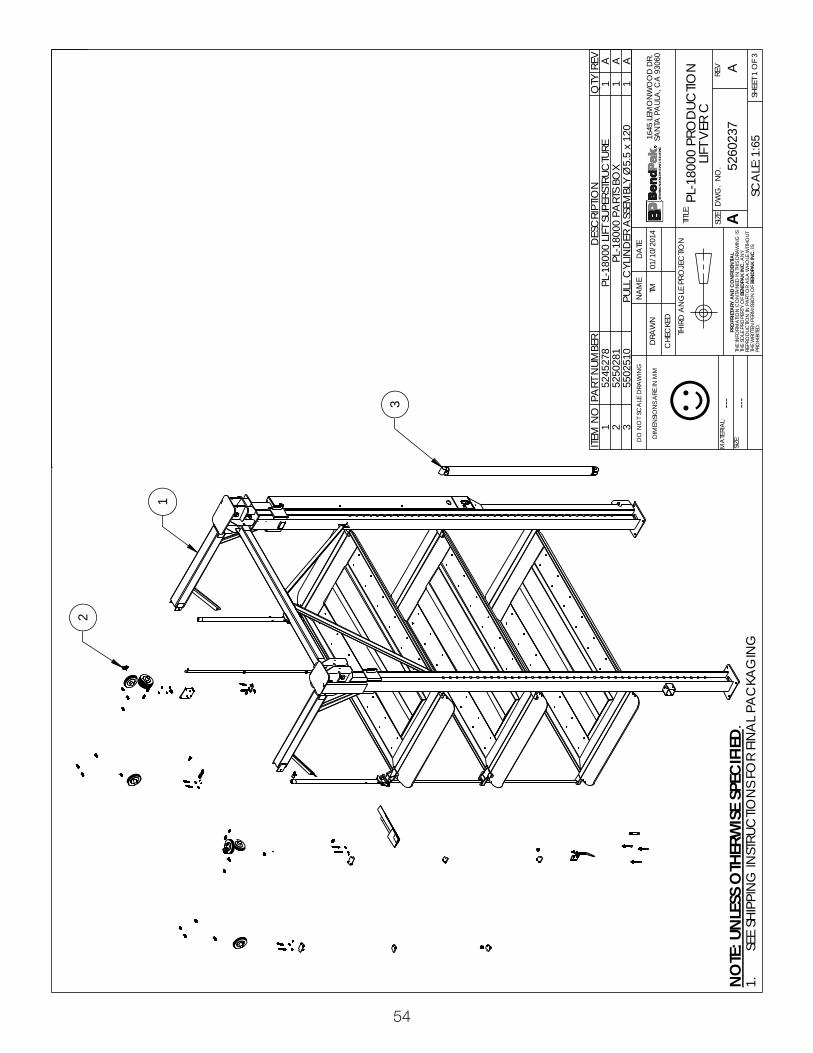
54
2
1
3
.A
MM
NI ERA S
NOIS
NEMI
D :EZIS
:LAIRET
AM
GNI
WAR
D ELA
CS TO
N O
D
SI
GNI
WARD SIHT
NI DE
NIATN
OC
NOITA
MROF
NI EHT F
O YTREPORP EL
OS EHT Y
NA
TUOHTI
W ELOH
W A SA RO TRAP
NI N
OITCU
DORPER
FO
NOISSI
MREP NETTIR
W EHT SI
.DETIBIH
ORP56:1 :EL
ACS
3 FO 1 TEEHS
VER.
ON .
GW
DEZIS
:ELTIT
EM
AN
ETA
D
DEKCEH
C
NW
ARD
.RD
DO
OW
NO
MEL 546106039
AC ,
ALUAP
ATN
ASMT
4102/01/10
NOIT
CEJORP EL
GN
A DRIHT
A7320625
N
OITCU
DORP 00081-LP
C REV TFIL
GNI
GAK
CAP L
ANIF R
OF SN
OITCURTS
NI G
NIPPIHS EES.1
DEIFICEPS
ESIWREHT
OSSELNU:ET
ON
☺L
AITNEDIF
NO
CD
NA
YRATEIRP
ORP
.C
NIK
APDNEB
.CNI
KAPD
NEB
NOISIVER
VERN
OITPIRCSE
DET
AD
YB DETI
DE#
OCE
A4010625
MORF
DEVIRED ,ES
AELER N
OITCU
DORP
4102/01/10MT
93600
ON
METIREB
MUN TR
APN
OITPIRCSE
DYT
QVER
18725425
ERUTCURTSREPUS TFIL 00081-LP
1A
21820525
XOB STR
AP 00081-LP1
A3
0152055021 x 5.5
Ø YLBMESS
A RED
NILYC LLUP
1A
--- ---

55
4
11
21
1
8
3
6
21
5
2
01
9
41
7
31
.A
MM
NI ERA S
NOIS
NEMI
D :EZIS
:LAIRET
AM
GNI
WAR
D ELA
CS TO
N O
D
SI
GNI
WARD SIHT
NI DE
NIATN
OC
NOITA
MROF
NI EHT F
O YTREPORP EL
OS EHT Y
NA
TUOHTI
W ELOH
W A SA RO TRAP
NI N
OITCU
DORPER
FO
NOISSI
MREP NETTIR
W EHT SI
.DETIBIH
ORP56:1 :EL
ACS
1 FO 1 TEEHS
VER.
ON .
GW
DEZIS
:ELTIT
EM
AN
ETA
D
DEKCEH
C
NW
ARD
.RD
DO
OW
NO
MEL 546106039
AC ,
ALUAP
ATN
ASMT
4102/80/10
NOIT
CEJORP EL
GN
A DRIHT
A8725425
TFIL 00081-LPERUT
CURTSREPUS
GNI
GAK
CAP L
ANIF R
OF SN
OITCURTS
NI G
NIPPIHS EES.1
DEIFICEPS
ESIWREHT
OSSELNU:ET
ON
☺L
AITNEDIF
NO
CD
NA
YRATEIRP
ORP
.C
NIK
APDNEB
.CNI
KAPD
NEB
NOISIVER
VERN
OITPIRCSE
DET
AD
YB DETI
DE#
OCE
A9735425
MORF
DEVIRED ,ES
AELER N
OITCU
DORP
4102/80/10MT
93600
YLBMESS
A TXEN
7320625
METIO
N TR
APREB
MUN
NOITPIR
CSED
YTQ
VER1
9280065T
NEM
DLEW TS
OP REW
OP 00081-LP1
A2
0380065T
NEM
DLEW TS
OP LORT
NO
C TN
ORF 00081-LP1
A3
3465125YLB
MESSA X
OBLLUP 00081-LP1
A4
7465125YLB
MESSA YTEF
AS KAERB ELB
AC 0 0081/00041-LP
4A
54465125
YLBMESS
A D
OR G
NITFIL PM
AR 00081-LP4
A6
1070265T
NEM
DLEW P
MAR P
OT 00081-LP1
A7
0280065T
NEM
DLEW P
MAR EL
DDI
M 00081-LP1
A8
51 80065T
NEM
DLEW P
MAR
MOTT
OB 00081/00041-LP1
A9
9750065T
NEM
DLEW EBUT SS
ORC
GN
OL 00081/00041-LP1
B01
4850065T
NORF TR
OHS ,TNE
MDLE
W EBUT SSOR
C 00081/00041-LP1
B11
8370065R
AER TROHS ,T
NEM
DLEW EBUT S S
ORC 00081/00041-LP
1A
216731275
ELG
NA T
NORF 00081/00041-LP
2C
315731275
ELG
NA R
AER 00081/00041-LP2
C41
7731275EL
GN
A EDIS 00081/00041-LP
2C
--- ---

56
ALIATED8:
1ELA
CS
7
6
5
8
A
4
2
1
9
3
.A
MM
NI ERA S
NOIS
NEMI
D :EZIS
:LAIRET
AM
GNI
WAR
D ELA
CS TO
N O
D
SI
GNI
WARD SIHT
NI DE
NIATN
OC
NOITA
MROF
NI EHT F
O YTREPORP EL
OS EHT Y
NA
TUOHTI
W ELOH
W A SA RO TRAP
NI N
OITCU
DORPER
FO
NOISSI
MREP NETTIR
W EHT SI
.DETIBIH
ORP55:1 :EL
ACS
1 FO 1 TEEHS
VER.
ON .
GW
DEZIS
:ELTIT
EM
AN
ETA
D
DEKCEH
C
NW
ARD
.RD
DO
OW
NO
MEL 546106039
AC ,
ALUAP
ATN
ASMT
4102/4 1/10
NOIT
CEJORP EL
GN
A DRIHT
A8155715
TUOES
OLC 00081-LP
ERUTCURTSREPUS
GELC REV
GNI
GAK
CAP L
ANIF R
OF SN
OITCURTS
NI G
NIPPIHS EES.1
DEIFICEPS
ESIWREHT
OSSELNU:ET
ON
☺L
AITNEDIF
NO
CD
NA
YRATEIRP
ORP
.C
NIK
APDNEB
.CNI
KAPD
NEB
NOISIVER
VERN
OITPIRCSE
DET
AD
YB DETI
DE#
OCE
A0645715
MORF
DEVIRED ,ES
AELER N
OITCU
DORP
4102/41/10MT
93600
ON
METIREB
MUN TR
APN
OITPIRCSE
DYT
QVER
18280065
TNE
MDLE
W TSOP K
CAB TU
O ESOL
C 00081-LP1
A2
7280065T
NEM
DLEW TS
OP TN
ORF TUO ES
OLC 00081-LP
1A
39750065
TNE
MDLE
W EBUT SSOR
C G
NOL 00081/00041-LP
1B
47731275
ELG
NA E
DIS 00081/00041-LP2
C5
2435455T
ALF 81M REHS
AW
01-
60535455
LS 82 x 81M REHS
AW
8-
72025355
8.8 LC 5.2 x 81
M TUN
8-
89130355
8.8 LC 05 x 5.2 x 81
M BHH8
-9
8030355"7 x "4/3 B
A8
-
HTIW ESU R
OF7320625
--- ---
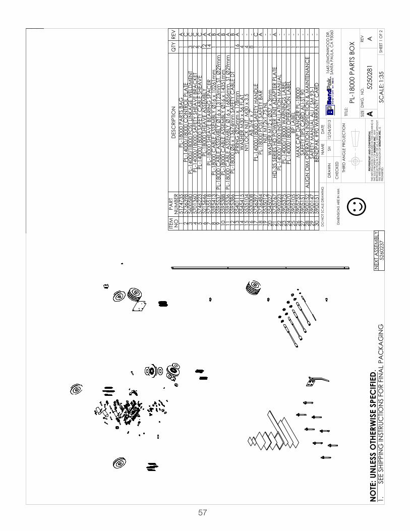
57
DIM
ENSI
ON
S A
RE IN
MM
☺
REV
ISIO
NRE
VD
ESC
RIPT
ION
DA
TEED
ITED
BY
ECO
#A
PRO
DUC
TION
REL
EASE
, DER
IVED
FRO
M 5
2500
9901
/08/
2014
TM00
639
NEX
T A
SSEM
BLY
5260
237
ITEM
N
OPA
RT
NUM
BER
DES
CRI
PTIO
NQ
TYRE
V1
5174
735
PL-1
8000
PA
RTS
BAG
1A
257
3639
8PL
-140
00/1
8000
CO
NTR
OL
PLA
TE1
C3
5600
580
PL-1
4000
/180
00 P
OST
LIN
KAG
E W
ELD
MEN
T3
C4
5701
360
PL-1
4000
/180
00 S
AFE
TY S
HEA
VE
BRA
CKE
T2
C5
5746
223
PL-1
4000
/180
00 S
AFE
TY C
ABL
E SH
EAV
E2
C6
5215
646
PL-1
8000
SHE
AV
E A
SSEM
BLY
12A
757
3551
8PL
-180
00 S
HEA
VE
BEA
RIN
G S
PAC
ER14
A8
5595
413
PL-1
8000
CA
BLE
ASS
EMBL
Y Ø
16 x
102
61m
m1
B9
5595
537
PL-1
8000
CA
BLE
ASS
EMBL
Y Ø
16 x
131
23m
m S
T, Ø
29m
m1
A10
5595
388
PL-1
8000
CA
BLE
ASS
EMBL
Y Ø
16 x
143
51m
m1
B11
5595
536
PL-1
8000
CA
BLE
ASS
EMBL
Y Ø
16 x
168
56m
m, S
T Ø
29m
m1
A12
5595
386
PL-1
8000
Ø6
x 13
674m
m S
AFE
TY C
ABL
E D
T1
B13
5540
111
SPRI
NG
Ø25
mm
x 1
78m
m16
A14
5545
415
WA
SHER
M30
x 5
6 FL
AT
4-
1555
3510
4N
YLO
CK
NUT
M30
x 3
.54
-16
5530
308
AB
3/4"
x 7
"8
-17
5736
397
PL-1
4000
/180
00 S
AFE
TY H
AN
DLE
1C
1857
3648
4PL
-180
00 P
OST
SA
FETY
BA
R1
A19
5535
012
NUT
M12
x1.7
5 N
L1
-20
5545
027
WA
SHER
M12
x Ø
37 x
3m
m1
-21
5735
767
HD-3
5 SE
RIES
HD
PO
WER
UN
IT A
DA
PTER
PLA
TE1
A22
5900
223
PL-1
4000
/180
00 IN
STA
LLA
TION
MA
NUA
L1
-23
5905
375
PL-1
4000
/180
00 W
ARN
ING
S LA
BEL
1-
2459
0537
0PL
-140
00/1
8000
OPE
RATIO
N L
ABE
L1
-25
5905
105
BP L
ABE
L1
-26
5905
755
MA
X C
AP
DA
NG
ER P
L-18
000
1-
2759
0515
1SA
FETY
TIP
S C
ARD
ALI
-ST
901
-28
5900
152
ALI
GN
OIM
OPE
RATIO
N IN
SPEC
TION
& M
AIN
TEN
AN
CE
1-
2959
0014
7SA
FETY
MA
NUA
L A
LI /
SM
93-
11
-30
5900
151
BEN
DPA
K #
90 W
ARR
AN
TY C
ARD
1-
SHE
ET 1
OF
2
REV
DW
G.
NO
.
ASIZETITLE
:
NA
ME
DA
TE
CHE
CKE
D
DRA
WN
A
1645
LEM
ON
WO
OD
DR.
SAN
TA P
AUL
A, C
A 9
3060
PRO
PRIE
TARY
AN
D C
ON
FIDE
NTIA
LTH
E IN
FORM
ATIO
N C
ON
TAIN
ED IN
THI
S D
RAW
ING
IS
THE
SOLE
PRO
PERT
Y O
F BE
NDP
AK
INC
. AN
Y RE
PRO
DUC
TION
IN P
ART
OR
AS
A W
HOLE
WITH
OUT
TH
E W
RITT
EN P
ERM
ISSI
ON
OF
BEN
DPA
K IN
C. I
S PR
OHI
BITE
D.
NO
TE: U
NLE
SS O
THER
WIS
E SP
ECIF
IED.
SH
5250
281
PL-1
8000
PA
RTS
BOX
12/2
4/20
13
DO
NO
T SC
ALE
DRA
WIN
G
1:35
SCA
LE:
THIR
D A
NG
LE P
ROJE
CTIO
N
SEE
SHIP
PIN
G IN
STRU
CTIO
NS
FOR
FIN
AL
PAC
KAG
ING
1.
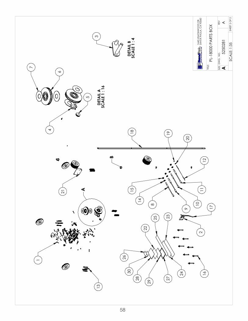
58
A
B
1
18
17
8
9
15
14
1110
122
20
19
21
16
23
24
27
2925
22
30
28
26
13
DETA
IL B
SC
ALE
1 :
43DE
TAIL
A
SCA
LE 1
: 16
4
5
7
6
SHE
ET 2
OF
2
REV
DW
G.
NO
.
ASIZETITLE
:
A
1645
LEM
ON
WO
OD
DR.
SAN
TA P
AUL
A, C
A 9
3060
5250
281
PL-1
8000
PA
RTS
BOX
1:35
SCA
LE:

59
DIM
ENSI
ON
S A
RE IN
MM
☺
REV
ISIO
NRE
VD
ESC
RIPT
ION
DA
TEED
ITED
BY
ECO
#A
PRO
DUC
TION
REL
EASE
, DER
IVED
FRO
M 5
1746
9001
/08/
2014
TM00
639
NEX
T A
SSEM
BLY
5250
281
ITEM
NO
PART
NUM
BER
DES
CRI
PTIO
NQ
TYRE
V1
5545
005
M6
FLA
T W
ASH
ER6
--2
5530
027
HHB
M6
x 1.
0 x
352
--3
5535
357
NUT
M6
x 1.
0 N
L6
--4
5530
093
HHB
M6
x 1
x 20
4--
555
3501
3N
UT M
10 x
1.5
NL
11--
655
3074
8HH
B M
10 x
1.5
x 1
00m
mL
5--
755
4535
0W
ASH
ER M
18 x
28
SL24
--8
5545
342
WA
SHER
M18
FLA
T30
--9
5535
202
NUT
M18
x 2
.5 C
L 8.
824
--10
5530
319
HHB
M18
x 2
.5 x
50
CL
8.8
24--
1155
4517
7W
ASH
ER 1
-1/8
" x 2
"4
--12
5535
300
NUT
1-1
/8-1
2 N
N4
--13
5530
116
HHB
M12
x 1
.75
x 40
1--
1455
4502
7W
ASH
ER M
12 x
Ø37
x 3
mm
1--
1555
3535
4N
UT M
12 x
1.75
2--
1655
3032
0BH
PS M
4 x
0.7
x 6
4--
1755
4534
1W
ASH
ER M
10 x
Ø20
FLA
T9
--18
5530
760
HEX
HEA
D B
OLT
M10
x1.2
5x35
3--
1955
4000
3SP
RIN
G Ø
16m
m x
90m
m1
A20
5505
056
PL-1
8000
PUL
LBO
X C
LEV
IS P
IN1
A21
5505
057
CO
TTER
PIN
Ø6.
3 x
120m
m1
--22
5505
054
PL-1
8000
SIN
GLE
SHE
AV
E PI
N5
A23
5746
273
PL-1
8000
CYL
IND
ER B
OTT
OM
CLE
VIS
PIN
1A
2455
0571
5Ø
6 x
75m
m C
OTT
ER P
IN2
--25
5540
087
PULL
SPR
ING
Ø12
.7 x
51m
m8
A26
5535
201
NUT
M12
x 1
.75
CO
UPLI
NG
1B
2757
4625
3PL
-140
00/1
8000
SA
FETY
CA
BLE
CO
NN
ECTO
R1
B28
5530
217
HHB
M10
x 1
.5 x
58
1--
2957
3645
8PL
-140
00/1
8000
SA
FETY
CA
BLE
SPA
CER
1B
3055
4520
0W
ASH
ER M
10 x
Ø18
SL
4--
3155
3016
7HH
B M
10 x
1.5
x 4
5mm
4--
3255
3599
8N
UT M
10 x
1.5
4--
3355
3001
0HH
B M
8 x
1.25
x 2
58
--34
5535
001
NUT
M8
x 1.
25 N
L8
A35
5545
202
WA
SHER
M8
x Ø
15 S
L8
--36
5545
021
WA
SHER
M8
x Ø
20 F
LAT
8--
3755
3510
8SO
CKE
T SE
T SC
REW
M8x
1.25
x12m
m L
1PR
E38
5535
012
NUT
M12
x1.7
5 N
L24
--39
5530
289
FHSS
M12
x 1
.75
x 70
24--
4057
1619
4PL
-140
00/1
8000
RA
MP
GUI
DE
BUM
PER
16A
4157
1619
3PL
-180
00 M
IDD
LE R
AM
P G
UID
E BU
MPE
R8
A42
5736
806
PL-1
4000
/180
00 B
OTT
OM
RA
MP
BUM
PER
SPA
CER
8A
SHE
ET 1
OF
2
REV
DW
G.
NO
.
ASIZETITLE
:
NA
ME
DA
TE
CHE
CKE
D
DRA
WN
A
1645
LEM
ON
WO
OD
DR.
SAN
TA P
AUL
A, C
A 9
3060
PRO
PRIE
TARY
AN
D C
ON
FIDE
NTIA
LTH
E IN
FORM
ATIO
N C
ON
TAIN
ED IN
THI
S D
RAW
ING
IS
THE
SOLE
PRO
PERT
Y O
F BE
NDP
AK
INC
. AN
Y RE
PRO
DUC
TION
IN P
ART
OR
AS
A W
HOLE
WITH
OUT
TH
E W
RITT
EN P
ERM
ISSI
ON
OF
BEN
DPA
K IN
C. I
S PR
OHI
BITE
D.
NO
TE: U
NLE
SS O
THER
WIS
E SP
ECIF
IED.
TM
5174
735
PL-1
8000
PA
RTS
BAG
01/0
8/20
14
DO
NO
T SC
ALE
DRA
WIN
G
1:35
SCA
LE:
THIR
D A
NG
LE P
ROJE
CTIO
N
SEE
SHIP
PIN
G IN
STRU
CTIO
NS
FOR
FIN
AL
PAC
KAG
ING
1.

60
A
B
C
D
E F GH
24 23
37
DETA
IL E
SC
ALE
1 :
1220
2
21
DETA
IL B
SC
ALE
1 :
10
25
39
40
38
DETA
IL D
SC
ALE
1 :
10
11
12
1315
1426
16
42
DETA
IL A
SC
ALE
1 :
10
1817
4
1
56
10
9
8
7
22
3
DETA
IL G
SC
ALE
1 :
6
31
30
32
34
36
35
33
DETA
IL F
SC
ALE
1 :
8
28
29
27
DETA
IL C
SC
ALE
1 :
4
19
DETA
IL H
SC
ALE
1 :
4
41
SHE
ET 2
OF
2
REV
DW
G.
NO
.
ASIZETITLE
:
A
1645
LEM
ON
WO
OD
DR.
SAN
TA P
AUL
A, C
A 9
3060
5174
735
PL-1
8000
PA
RTS
BAG
1:40
SCA
LE:

61
DIM
ENSI
ON
S A
RE IN
MM
☺
3
1
2
REV
ISIO
NRE
VD
ESC
RIPT
ION
DA
TEED
ITED
BY
ECO
#A
PRO
DUC
TION
REL
EASE
, DER
IVED
FRO
M 5
2102
1008
/29/
2014
TM00
668
NEX
T A
SSEM
BLY
AC
CES
SORY
ITEM
N
OPA
RT
NUM
BER
DES
CRI
PTIO
NQ
TYRE
V1
5570
048
PL-1
4000
HYD
RAUL
IC H
OSE
ASS
Y Ø
12 x
655
3mm
DS
1A
255
7004
7PL
-140
00 H
YDRA
ULIC
HO
SE A
SSEM
BLY
Ø6.
4 x
4115
mm
D
S1
A3
5550
005
FTG
ELB
-08
JIC
-06L
ORB
1A
SHE
ET 1
OF
1
REV
DW
G.
NO
.
ASIZETITLE
:
NA
ME
DA
TE
CHE
CKE
D
DRA
WN
A
1645
LEM
ON
WO
OD
DR.
SAN
TA P
AUL
A, C
A 9
3060
PRO
PRIE
TARY
AN
D C
ON
FIDE
NTIA
LTH
E IN
FORM
ATIO
N C
ON
TAIN
ED IN
THI
S D
RAW
ING
IS
THE
SOLE
PRO
PERT
Y O
F BE
NDP
AK
INC
. AN
Y RE
PRO
DUC
TION
IN P
ART
OR
AS
A W
HOLE
WITH
OUT
TH
E W
RITT
EN P
ERM
ISSI
ON
OF
BEN
DPA
K IN
C. I
S PR
OHI
BITE
D.
NO
TE: U
NLE
SS O
THER
WIS
E SP
ECIF
IED.
TM
5210
077
PL-1
4000
SIN
GLE
UN
IT HY
DRA
ULIC
KIT
08/2
9/20
14
DO
NO
T SC
ALE
DRA
WIN
G
1:4
SCA
LE:
THIR
D A
NG
LE P
ROJE
CTIO
N
SEE
SHIP
PIN
G IN
STRU
CTIO
NS
FOR
FIN
AL
PAC
KAG
ING
1.

62
DIM
ENSI
ON
S A
RE IN
MM
☺
1
3
4
5
2
6
REV
ISIO
NRE
VD
ESC
RIPT
ION
DA
TEED
ITED
BY
ECO
#A
PRO
DUC
TION
REL
EASE
12/3
0/20
11TM
0047
4
NEX
T A
SSEM
BLY
AC
CES
SORY
ITEM
NO
PART
NUM
BER
DES
CRI
PTIO
NQ
TYRE
V1
5570
191
PL-1
4000
HYD
RAUL
IC H
OSE
ASS
EMBL
Y Ø
10 x
22
00m
m D
S1
A
255
7019
2PL
-140
00 H
YDRA
ULIC
HO
SE A
SSEM
BLY
Ø10
x
4450
mm
DS
1A
355
5012
8FT
G N
PL -0
6 N
PT x
-06
NPT
1-
455
5014
2FT
G N
PL -0
6 O
RB x
-06
F N
PT1
-5
5550
103
FTG
ELB
-04
JIC
-06
ORB
1-
655
5017
5FT
G T
EE -0
6 JI
C -0
6 JI
C -0
6 JI
C1
-
SHE
ET 1
OF
1
REV
DW
G.
NO
.
ASIZE
TITLE
:
NA
ME
DA
TE
CHE
CKE
D
DRA
WN
SIZE
:
MA
TERI
AL:
A
1645
LEM
ON
WO
OD
DR.
SAN
TA P
AUL
A, C
A 9
3060
PRO
PRIE
TARY
AN
D C
ON
FIDE
NTIA
LTH
E IN
FORM
ATIO
N C
ON
TAIN
ED IN
THI
S D
RAW
ING
IS
THE
SOLE
PRO
PERT
Y O
F BE
NDP
AK
INC
. AN
Y RE
PRO
DUC
TION
IN P
ART
OR
AS
A W
HOLE
WITH
OUT
TH
E W
RITT
EN P
ERM
ISSI
ON
OF
BEN
DPA
K IN
C. I
S PR
OHI
BITE
D.
NO
TE: U
NLE
SS O
THER
WIS
E SP
ECIF
IED.
TM
5210
215
PL-1
4000
MUL
TIPLE
UN
IT HY
DRA
ULIC
AD
D O
N K
IT--- ---
12/3
0/20
11
DO
NO
T SC
ALE
DRA
WIN
G
1:4
SCA
LE:
THIR
D A
NG
LE P
ROJE
CTIO
N
SEE
SHIP
PIN
G IN
STRU
CTIO
NS
FOR
FIN
AL
PAC
KAG
ING
1.
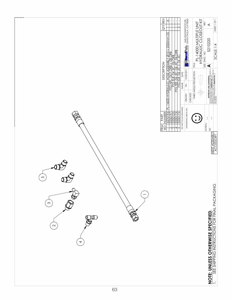
63
DIM
ENSI
ON
S A
RE IN
MM
☺
23
5
1
4
REV
ISIO
NRE
VD
ESC
RIPT
ION
DA
TEED
ITED
BY
ECO
#A
PRO
DUC
TION
REL
EASE
12/3
0/20
11TM
0047
4
NEX
T A
SSEM
BLY
AC
CES
SORY
ITEM
N
OPA
RT
NUM
BER
DES
CRI
PTIO
NQ
TYRE
V1
5570
193
PL-1
4000
HYD
RAUL
IC H
OSE
ASS
EMBL
Y Ø
10 x
250
0mm
DS
1A
255
5019
7FT
G N
PL -0
6 F
ORB
x -0
8 O
RB1
-3
5550
103
FTG
ELB
-04
JIC
-06
ORB
1-
455
5017
4FT
G T
EE -0
6 JI
C -0
6 JI
C -0
6 O
RB1
-5
5550
173
FTG
ELB
-06
JIC
x -0
6 JI
C2
-
SHE
ET 1
OF
1
REV
DW
G.
NO
.
ASIZE
TITLE
:
NA
ME
DA
TE
CHE
CKE
D
DRA
WN
SIZE
:
MA
TERI
AL:
A
1645
LEM
ON
WO
OD
DR.
SAN
TA P
AUL
A, C
A 9
3060
PRO
PRIE
TARY
AN
D C
ON
FIDE
NTIA
LTH
E IN
FORM
ATIO
N C
ON
TAIN
ED IN
THI
S D
RAW
ING
IS
THE
SOLE
PRO
PERT
Y O
F BE
NDP
AK
INC
. AN
Y RE
PRO
DUC
TION
IN P
ART
OR
AS
A W
HOLE
WITH
OUT
TH
E W
RITT
EN P
ERM
ISSI
ON
OF
BEN
DPA
K IN
C. I
S PR
OHI
BITE
D.
NO
TE: U
NLE
SS O
THER
WIS
E SP
ECIF
IED.
TM
5210
220
PL-1
4000
MUL
TIPLE
UN
IT HY
DRA
ULIC
CLO
SEO
UT K
IT--- ---
12/3
0/20
11
DO
NO
T SC
ALE
DRA
WIN
G
1:4
SCA
LE:
THIR
D A
NG
LE P
ROJE
CTIO
N
SEE
SHIP
PIN
G IN
STRU
CTIO
NS
FOR
FIN
AL
PAC
KAG
ING
1.

64
For Parts Or ServiceContact:
BendPak Inc. / Ranger Products1645 Lemonwood Dr.
Santa Paula, CA. 93060
Tel: 1-805-933-9970Toll Free: 1-800-253-2363
Fax: 1-805-933-9160
www.bendpak.com
p/n 5900223