Embed Size (px)
Citation preview

Automatic Transfer Switch OTM_C_20D
Installation and Operation Instructions

Contents
1 SYMBOLS & TERMS ............................................................................................................................ 1
1.1 USE OF SYMBOLS ..................................................................................................................................... 11.2 EXPLANATIONS OF ABBREVIATIONS AND TERMS ............................................................................................... 1
2 PRODUCT OVERVIEW ......................................................................................................................... 2
2.1 PRODUCT OVERVIEW AND PACKING .............................................................................................................. 22.2 OTM_C_20D SWITCHING SEQUENCE .......................................................................................................... 32.2.1 Line 1 Priority (default mode) .............................................................................................................. 32.2.2 No line priority .................................................................................................................................... 3
3 QUICK START ...................................................................................................................................... 4
3.1 OPERATING THE SWITCH MANUALLY (LOCAL OPERATION).................................................................................... 43.2 AUTOMATIC OPERATION ............................................................................................................................ 53.3 LOCAL TEST OPERATION ............................................................................................................................. 63.4 LOCKING ............................................................................................................................................... 73.4.1 Locking the electrical operation ........................................................................................................... 73.4.2 Locking the manual operation ............................................................................................................. 7
4 INTERFACE AND SETTINGS .................................................................................................................. 8
4.1 BUTTONS .............................................................................................................................................. 84.2 LEDS ................................................................................................................................................... 84.3 DIP SWITCH SETTING ................................................................................................................................ 94.4 TERMINAL ............................................................................................................................................. 9
5 TECHNICAL DATA .............................................................................................................................. 10
6 INSTALLATION .................................................................................................................................. 11
6.1 INSTALLATION METHOD ........................................................................................................................... 116.2. INSTALLATION DIMENSIONS ...................................................................................................................... 13
7. OPTIONAL ACCESSORIES .................................................................................................................. 13
7.1 BRIDGING BARS ..................................................................................................................................... 147.2 TERMINAL SHROUDS............................................................................................................................... 157.3 AUXILIARY CONTACT BLOCKS ..................................................................................................................... 15
8. MAINTENANCE AND COMMON TROUBLESHOOTING ....................................................................... 16
8.1 MAINTENANCE ..................................................................................................................................... 168.2 COMMON TROUBLESHOOTING .................................................................................................................. 16
9. APPENDIX ........................................................................................................................................ 17
9.1 WIRING DIAGRAM ......................................................................................................................................... 17


1
1 Symbols & Terms
1.1 Use of symbols
Hazardous voltage: warns about a situation where a hazardous voltage maycause physical injury to a person or damage to equipment.
General warning: warns about a situation where something other than electricalequipment may cause physical injury to a person or damage to equipment.
Caution: provides important information or warns about a situation that mayhave a detrimental effect on equipment.
Information: provides important information about the equipment.
1.2 Explanations of abbreviations and terms
OTM_C_20D Automatic transfer switch, the type nameLN1-Switch I Power supply line, e.g. the primary lineLN2-Switch II Power supply line, e.g. the secondary line used in emergency casesEMERG OFF (firecontrol system)
Used to drive the automatic transfer switch transfers to the “O”position when receiving EMRG OFF signal.
AUTO Automatic modeTEST The switch performs “switching cycle test” as the pre-set program
Table 1 Explanations of abbreviations and terms

2
2 Product overview
2.1 Product overview and packing
The OTM_C20D automatic transfer switches can be used as a source transfer switch in a three-phase or single-phase networks. Monitored conditions are, no-voltage and phase-loss. Youcan operate the switch, either manually with the handle or automatically by the "AUTO"mode. The automatic operation modes include Line 1 priority, no line priority and manualback switching mode.
Figure 1 OTM_C_20D automatic transfer switch
1. Handle for manual operation2. Place for auxiliary contact blocks3. Push button4. Mimic panel5. Voltage sensing connections6. Locking clip for padlock
7. Locking latch for releasing the handleand locking electrical control
8. Locking clip for locking manual operation9. Dip switches10. Connecting terminal
The standard package includes: 1.automatic transfer switch, 2.handle, 3.handle storageclip 4.terminal plug, 5.mounting kit

3
2.2 OTM_C_20D switching sequence
2.2.1 Line 1 Priority (default mode)
The switching sequence can be summarized in following steps:l An fault occurs on Line 1 (LN1), while Line 2 (LN2) functions normallyl Change-over switch (Switch I) to the position 0l Change-over switch (Switch II) to the position II
And the back switching sequence can be summarized in the following steps:l The Line 1 will start the normal functioningl Change-over switch (Switch II) to the position 0l Change-over switch (Switch I) to the position I
Figure 2 Automatic Switching Sequences in OTM_C_20D, Line 1 priority
2.2.2 No line priority
The switching sequence can be summarized in following steps:l An fault occurs on Line 1 (LN1), while Line 2 (LN2) functions normallyl Change-over switch (Switch I) to the position 0l Change-over switch (Switch II) to the position II
And the back switching sequence can be summarized in the following steps:l The Line 1 will start the normal functioningl Change-over switch stays in position IIl An anomaly occurs on the Line 2 (LN2)l Change-over switch (Switch II) to the position 0l Change-over switch (Switch I) to the position I
Figure 3 Automatic Switching Sequences in OTM_C_20D, No line priority

4
3 Quick start
3.1 Operating the switch manually (local operation)
To operate the switch manually:1. Attach the handle to the switch panel. You can attach the handle in any position.2. When the handle is attached, the automatic transfer switch will automatically be in
Manual mode and won’t operate automatically in case of line failure. The AUTO LED onthe mimic panel is OFF.
Figure 4 Operating the switch manually
When the handle is inserted into the switch, the switch will enter “manual mode”with the automatic operation disabled.
Do not adjust wires when the transfer switch is being energized.
Before the power-on operation of the transfer switch, please operate the switchmanually to confirm it is in normal function.
With the power supply function in “normal” and without the handle inserted andEMRG OFF signals, the initially energized switch will enter automatic mode andtransfer to the main line. Keep the handle inserted if you do not want the switchto be in automatic mode upon initial energization.

5
3.2 Automatic operation
OTM_C_20D must be in automatic mode and the "AUTO" LED is on in order that the switchcan perform automatic transfer cycles according to the pre-set operating mode.
To operate the switch electrically:l If the handle inserted,
1. Press handle locking clip and remove the handle from the switch.2. Press “AUTO” button and the "AUTO" LED will be ON, indicating automatic mode.
l If handle is not inserted1. If "AUTO" LED blinks or OFF, press “AUTO” button and the "AUTO" LED will be ON,
indicating automatic mode.2. Automatic operation includes two operating modes: Line 1 priority (factory default
setting) and No line priority.
Figure 5 Selecting the automatic transfer OTM_C_20D switch to Auto mode
○,3
○,2
○,1

6
3.3 Local test operation
In automatic mode, "AUTO" LED is ON and you can press the “TEST” button on the panel tolead it to "TEST" mode:
Operation sequences:1. Ensure switch in "AUTO" mode2. Press the “TEST” button and the Auto LED will blink, indicating the activation of "TEST"
mode.Under "TEST" mode, the automatic transfer switch will transfer by one cycle and finallyreturn to its original position.e.g., when the switch is in Position I:Press the "TEST" button; the switch transfers to Position “O”à to Position “II”à toPosition “O”à to Position “I”. During process, pressing the "TEST" button again will beinvalid until it returns to its original position.During "TEST" process, press the "AUTO" button will cancel "TEST" mode and return to"AUTO" mode.
3. After test, press "AUTO" button to return the automatic operation.
Figure 6 Local test of OTM_C_20D
In the test sequence, the main power supply circuit will be closed.
If the test sequence is interrupted due to power failure, the automatic transferswitch will enter "automatic mode" after power recovery.
○,1 ○,2 ○,3

7
3.4 Locking
3.4.1 Locking the electrical operation
The switch can be padlocked in any position, causing that all operating modes and testoperations are disabled and handle cannot be inserted. See below for operation:
Figure 7 Locking the electrical operation
3.4.2 Locking the manual operation
By default, the manual operation can only be locked in position 0. The handle can bepadlocked by pulling out the clip from the handle and place the padlock on the handle.
Figure 8 Locking the manual operation
φ 5-6 mm
○,1
○,2
○,3
○,4

8
4 Interface and Settings
4.1 Buttons
Figure 9 Buttons of OTM_C_20D
AUTO buttonIt can lead you to "AUTO" mode. When the switch is in “Test” or fault status, you can pressthe "AUTO" button until the "Auto" LED on.TEST buttonIt can lead you to "TEST" mode. First you must on "AUTO" mode, then you can press the "TEST"button while the "Auto" LED blinking. You must press the "AUTO" button after the test iscomplete.
4.2 LEDs
Figure 10 LEDs of OTM_C_20D
LED Display Status descriptionLN1/LN2 ON Source available
Blinking Overvoltage, undervoltage or phase lossOFF Source not available
I/II ON Switch I or II closedOFF Switch I or II openBlinking Switching failure.
Auto ON Transfer switch in automatic modeBlinking Transfer switch in test mode or invalid settingOFF Transfer switch in manual mode
EMRG OFF ON Receiving emergency signalsOFF No emergency signals input
Table 2 LEDs

9
4.3 Dip switch settingThe DIP switch is used to set the working modes and poles of transfer switch.
Figure 11 DIP switch
No. Function Setting1, 2 Pole setting 01 10 11 00
2 poles 3 poles 4 poles Invalid setting3 Mode
setting0 1No line priority Line priority LN1
Table 3 DIP switch
The 9-bit dip is used to control the switch for circuit testing, and the mismatchwith the load power supply will result in testing and transfer failure. Therefore,carefully read this guide and set correct parameters based on the actual situationbefore using this product.
4.4 TerminalEMRG OFF: Input the 24VDC EMRG OFF signals for at least 1s until the switch transfers to theEMRG OFF position and the EMRG OFF LED is on. At this time, the switch cannot enter theautomatic or test mode and only handle operation is allowed. After the signal is canceled,press "AUTO" to quit EMRG OFF.
Figure 12 EMRG OFF terminal

10
5 Technical data
Automatic transfer switch ParametersRated operational voltage Ue[V] 220~240 V AC 50~60 HzOperating voltage range 0.8~1.2 Ue
Error range of monitoring ±5%Operating angle 90° ( O-I, I-O, O-II, II-O) 180° ( I-O-II, II-O-I)Transfer time for contact 610 ms ± 10%Transfer time for switch 2.5 s ± 10%Output relay utilization category 3A,AC1,250VElectromagnetic compatibility Class BIngress Protection Rating IP20, front panelRated impulse withstand voltageUimp
8 kV (6 kV for control circuit, disconnect the powerline of the control circuit before the dielectric voltagewithstand test)
Operating temperature -25~55℃Transportation and storagetemperature
-40~70℃
Altitude Max. 2000 mTable 4 Technical data

11
6 Installation
6.1 Installation method
The switch can be installed using screws or a DIN rail.The fixed installation mode on the base board is as follows:
Figure 13 Installation of OTM_C_20D, screw
The DIN rail installation mode is as follows:First pry out the latch with an appropriate tool, as shown in Fig. 13
Figure 14 Installation of OTM_C_20D, DIN rail
2M4

12
After attaching the switch to the DIN-rail, push the latch back to lock it
Figure 15 Installation of OTM_C_20D, DIN rail
After attaching the switch to the DIN-rail, make sure you push the latch back tothe lock position, otherwise the switch may fall off.
Push!
13
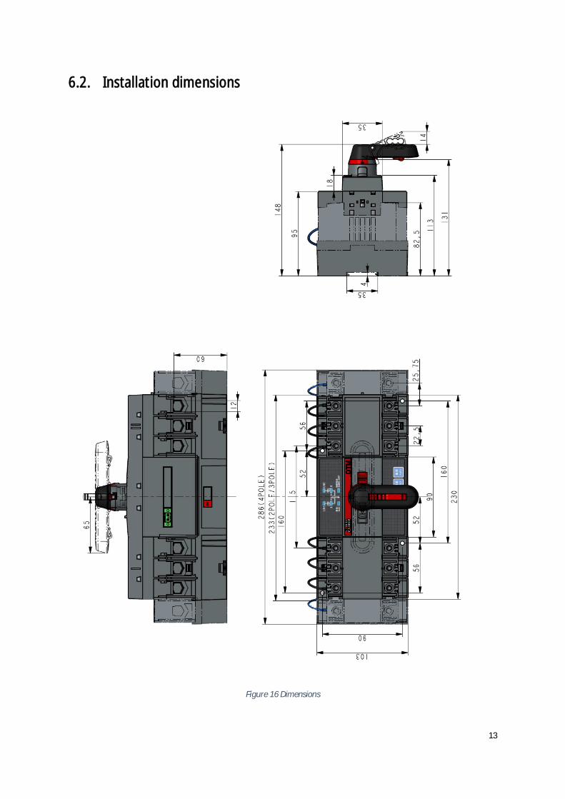
6.2. Installation dimensions
Figure 16 Dimensions

14
7. Optional accessories
7.1 Bridging bars
Figure 17 Bridging bars
6 Nm
OTM32~125F2C20D OMZC03OTM32~125F3C20D
OTM32~125F4C20D OMZC04
17
Number of conductors permitted tobe clamped on the terminal ≤2,Wire specification: 10-70mm2, 8-00AWG

15
Figure 18 Terminal shrounds
7.2 Terminal shrouds
7.3 Auxiliary contact blocks
I OA7G10 OA1G01Contact type NO NCIOII
II OA1G10 OA8G01Contact type NO NCIOII
OTS125T3
OTS125T1
OA7G10/OA1G01
OA2G11
0.8 Nm
0.75……2.5݉݉ଶ
18……14AWG
OA2G11Only suitable for 3-pole products
OA2G11 has two layersto provide a maximum of4 NO + 4 NC auxiliarycontacts.
○,1
○,2
○,3
○,4
Figure 19 Auxiliary contact blocks

16
8. Maintenance and common troubleshooting
8.1 Maintenance
To ensure the operation reliability of switches, regular switching tests should be performed(once every 3 months) to confirm normal function.
8.2 Common troubleshooting
No. Fault Description Fault Analysis Troubleshooting Method1 Power supply
functioning normally,but LED not ON
Control unit power supplyterminal not connectedwith switch wiring terminal
Check and connect theswitch wiring terminal
2 Power supply LEDfunctioning normallybut "AUTO" LED OFF, orno response with“AUTO” button pressed
Handle not pulled out orelectrical padlock notremoved
Pull out the handle orremove the padlock, andthen press the "AUTO"button
3 Transition failure incase of faulty powersupply
1. Switch not operating in"AUTO" mode2. Both power suppliesmalfunctioning
Make sure the switch isworking in "AUTO" mode;check and make sure bothpower supplies are notmalfunctioningsimultaneously;
4 EMRG OFF functionfailure
1. Check if the EMRG OFFsignal is 24V DC2. Too short duration ofEMRG OFF signal
Correctly switch on theEMRG OFF signal, whichshould only be 24V DC withthe duration ≥ 1 s
5 AUTO LED blinking withall other LEDs OFFNo response frombuttons
DIP switch for poles numberof power supply set to “00”
Check if the DIP switchsetup matches the phasenumber of switch powersupply.
6 “I” or “II” LED blinking Execution rejected duringswitching operation, thusexpected result notachieved
Manually set the switch toPosition “O”, and press the“AUTO” button to reset
Table 5 Troubleshooting

17
9. Appendix
9.1 Wiring diagram
Figure 20 Wiring Diagram

ABB Xinhui Low Voltage Switchgear Company LimitedJinguzhou Industrial Zone, Xinhui District, JiangmenCity, Guangdong Province, PRCPostal code: 529100Tel: 0750-6322200Fax: 0750-6677526http://www.abb.com.cn
2THT
3038
03P4
001-
D
v Read through this instruction book carefully before working on the switch, and keepthis instruction book to hand for later reference
v The images provided in this instruction book are for illustration purposes only andmay not match the actual product exactly
v This instruction book is subject to change for product updates without prior notice