Embed Size (px)
Citation preview

NB, NBGInstallation and operating instructions
GRUNDFOS INSTRUCTIONS

En
glish
(GB
)
2
English (GB) Installation and operating instructions
Original installation and operating instructions
CONTENTSPage
1. Symbols used in this document
2. General informationNB, NBG are non-self-priming, single stage, centrifugal volute pumps with axial suction port and radial discharge port.
NB pumps comply with EN 733.
NBG pumps comply with ISO 2858.
1. Symbols used in this document 2
2. General information 2
3. Delivery and handling 33.1 Delivery 33.2 Handling 3
4. Identification 44.1 Nameplate 44.2 Type key 5
5. Applications 75.1 Pumped liquids 7
6. Operating conditions 76.1 Ambient temperature and altitude 76.2 Liquid temperature 76.3 Max. operating pressure 86.4 Min. inlet pressure 86.5 Max. inlet pressure 86.6 Min. flow rate 86.7 Max. flow rate 86.8 Shaft seals 9
7. Pump without motor 107.1 Mounting of motor on pump housing
without feet 107.2 Mounting of motor on pump housing with
feet 12
8. Mechanical installation 148.1 Preparations before installation 148.2 Pump location 148.3 Connection 158.4 Foundation of NB, NBG pump without
base frame 158.5 Foundation of NB, NBG pump with base
frame 168.6 Pipework 198.7 Vibration dampening 208.8 Expansion joints 208.9 Measuring instruments 21
9. Flange forces and torques 22
10. Electrical connection 2410.1 Motor protection 2410.2 Frequency converter operation 24
11. Commissioning and startup 2511.1 General information 2511.2 Commissioning 2511.3 Priming 2511.4 Checking the direction of rotation 2511.5 Startup 2611.6 Shaft seal run-in period 2611.7 Start/stop 2611.8 Reference readings of monitoring
equipment 26
12. Maintenance 2712.1 Pump 2712.2 Mechanical shaft seals 2712.3 Motor 2712.4 Lubrication 27
13. Periods of inactivity and frost protection 27
14. Service 2714.1 Service kits 27
15. Technical data 2715.1 Electrical data 2715.2 Sound pressure level 27
16. Fault finding 28
17. Disposal 29
Warning
Prior to installation, read these installation and operating instructions. Installation and operation must comply with local regulations and accepted codes of good practice.
Warning
If these safety instructions are not observed, it may result in personal injury.
CautionIf these safety instructions are not observed, it may result in malfunction or damage to the equipment.
Note Notes or instructions that make the job easier and ensure safe operation.

En
glis
h (
GB
)
3
3. Delivery and handling
3.1 Delivery
The pumps are tested 100 % before leaving the factory. The test includes a function test where the pump performance is measured to ensure that the pump meets the requirements of relevant standards. Test certificates are available from Grundfos.
3.2 Handling
Weight: See label on the packing.
Pumps should be lifted by means of nylon straps and shackles or a hook as shown on figs. 1 to 3.
Fig. 1 Correct lifting of pump without base frame
Fig. 2 Correct lifting of pump with base frame
Fig. 3 Correct lifting of pump without motor
Fig. 4 Incorrect lifting of pump
Warning
Pump motors as from 4 kW are supplied with lifting eyes which must not be used for lifting the entire pump unit. See fig. 4.
TM
03
39
73
13
06
TM
04
51
79
28
09
TM
05
33
09
111
2T
M0
3 3
97
2 1
30
6

En
glish
(GB
)
4
4. Identification
4.1 Nameplate
Fig. 5 Example of nameplate for NB
Legend
TM
05
60
06
45
12
Pos. Description
1 Type designation
2 Model
3 Flow rate
4 Max. pressure/temperature
5 Country of origin
6 Pump speed
7 Pump head
8 Minimum efficiency index
9Hydraulic pump efficiency at best efficiency point
bar/°CMAX
m /h3 HQp/t
m n min-1Model
9614
5329
Type
B 96126252 P2 0612 000123.4 22.6 2900
16/120Made in Hungary
6
7
1
2
345
% DK-8850 Bjerringbro, Denmark
8 9
p0.70 68.8NB 32-125.1/142 AE-F-1-A-E-S-BAQE

En
glis
h (
GB
)
5
4.2 Type key
Model B
Example 1 (pump design according to EN 733) NB 32 -125 .1 /142 AE F 1 A E S BAQE
Example 2 (pump design according to ISO 2858) NBG 125 -100 -160 /160-142 A F 2 N K S DQQK
Type range
Nominal diameter of suction port (DN)
Nominal diameter of discharge port (DN)
Nominal impeller diameter [mm]
Reduced performance = .1
Actual impeller diameter [mm]
Code for pump version (the codes may be combined)
A Basic version
B Oversize motor
C Without motor
D Pump housing with feet
EWith ATEX approval, certificate or test report, the second character of the pump version code is an E
F Version with base frame
S With support blocks
X Special version (in case of further customisation than already listed)
Pipe connection
E Table E flange
F DIN flange
G ANSI flange
J JIS flange
Flange pressure rating (PN - nominal pressure)
1 10 bar
2 16 bar
3 25 bar
4 40 bar
5 Other pressure rating
Materials
Pump housing
Impeller Wear ring Shaft
A EN-GJL-250 EN-GJL-200 Bronze/brass 1.4301
B EN-GJL-250Bronze CuSn10
Bronze/brass 1.4301
C EN-GJL-250 EN-GJL-200 Bronze/brass 1.4401
D EN-GJL-250Bronze CuSn10
Bronze/brass 1.4401
E EN-GJL-250 EN-GJL-200 EN-GJL-250 1.4301
F EN-GJL-250Bronze CuSn10
EN-GJL-250 1.4301
G EN-GJL-250 EN-GJL-200 EN-GJL-250 1.4401
H EN-GJL-250Bronze CuSn10
EN-GJL-250 1.4401
I 1.4408 1.4408 1.4517 1.4462
J 1.4408 1.4408Carbon-graphite-filled PTFE (Graflon®)
1.4462

En
glish
(GB
)
6
Example 1 shows an NB 32-125.1 pump with these characteristics:
Example 2 shows an NBG 125-100-160 pump with these characteristics:
K 1.4408 1.4408 1.4517 1.4401
L 1.4517 1.4517 1.4517 1.4462
M 1.4408 1.4517 1.4517 1.4401
N 1.4408 1.4408Carbon-graphite-filled PTFE (Graflon®)
1.4401
P 1.4408 1.4517Carbon-graphite-filled PTFE (Graflon®)
1.4401
R 1.4517 1.4517Carbon-graphite-filled PTFE (Graflon®)
1.4462
S EN-GJL-250 1.4408 Bronze/brass 1.4401
T EN-GJL-250 1.4517 Bronze/brass 1.4462
U 1.4408 1.4517 1.4517 1.4462
W 1.4408 1.4517Carbon-graphite-filled PTFE (Graflon®)
1.4462
X Special version
Rubber parts in pump
Material of O-ring for pump cover
E EPDM
F FXM (Fluoraz®)
K FFKM (Kalrez®)
M FEPS (PTFE-sheathed silicone O-ring)
X HNBR
V FKM (Viton®)
Shaft seal arrangement
S Single seal
Code for mechanical shaft seal and shaft seal rubber parts
Example 1 (pump design according to EN 733) NB 32 -125 .1 /142 AE F 1 A E S BAQE
Example 2 (pump design according to ISO 2858) NBG 125 -100 -160 /160-142 A F 2 N K S DQQK
• reduced performance
• 142 mm impeller
• basic version
• ATEX approval, certificate or test report
• DIN flange to EN 1092-2 pipework connection
• 10 bar flange pressure rating
• cast iron pump housing, EN-GJL-250
• cast iron impeller, EN-GJL-200
• bronze/brass wear ring
• stainless steel shaft, EN 1.4301
• EPDM O-ring for pump cover
• single shaft seal arrangement
• BAQE shaft seal.
• 160-142 mm conical impeller
• basic version
• DIN flange to EN 1092-2 pipework connection
• 16 bar flange pressure rating
• stainless steel pump housing, EN 1.4408
• stainless steel impeller, EN 1.4408
• carbon-graphite-filled PTFE (Graflon®) wear ring
• stainless steel shaft, EN 1.4401
• FFKM O-ring for pump cover
• single shaft seal arrangement
• DQQK shaft seal.
En
glis
h (
GB
)
7
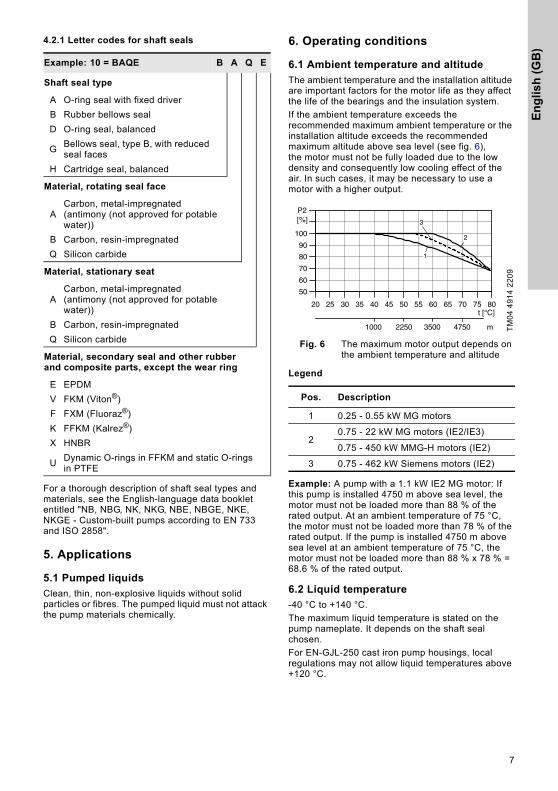
4.2.1 Letter codes for shaft seals
For a thorough description of shaft seal types and materials, see the English-language data booklet entitled "NB, NBG, NK, NKG, NBE, NBGE, NKE, NKGE - Custom-built pumps according to EN 733 and ISO 2858".
5. Applications
5.1 Pumped liquids
Clean, thin, non-explosive liquids without solid particles or fibres. The pumped liquid must not attack the pump materials chemically.
6. Operating conditions
6.1 Ambient temperature and altitude
The ambient temperature and the installation altitude are important factors for the motor life as they affect the life of the bearings and the insulation system.
If the ambient temperature exceeds the recommended maximum ambient temperature or the installation altitude exceeds the recommended maximum altitude above sea level (see fig. 6), the motor must not be fully loaded due to the low density and consequently low cooling effect of the air. In such cases, it may be necessary to use a motor with a higher output.
Fig. 6 The maximum motor output depends on the ambient temperature and altitude
Legend
Example: A pump with a 1.1 kW IE2 MG motor: If this pump is installed 4750 m above sea level, the motor must not be loaded more than 88 % of the rated output. At an ambient temperature of 75 °C, the motor must not be loaded more than 78 % of the rated output. If the pump is installed 4750 m above sea level at an ambient temperature of 75 °C, the motor must not be loaded more than 88 % x 78 % = 68.6 % of the rated output.
6.2 Liquid temperature
-40 °C to +140 °C.
The maximum liquid temperature is stated on the pump nameplate. It depends on the shaft seal chosen.
For EN-GJL-250 cast iron pump housings, local regulations may not allow liquid temperatures above +120 °C.
Example: 10 = BAQE B A Q E
Shaft seal type
A O-ring seal with fixed driver
B Rubber bellows seal
D O-ring seal, balanced
GBellows seal, type B, with reduced seal faces
H Cartridge seal, balanced
Material, rotating seal face
ACarbon, metal-impregnated(antimony (not approved for potable water))
B Carbon, resin-impregnated
Q Silicon carbide
Material, stationary seat
ACarbon, metal-impregnated(antimony (not approved for potable water))
B Carbon, resin-impregnated
Q Silicon carbide
Material, secondary seal and other rubber and composite parts, except the wear ring
E EPDM
V FKM (Viton®)
F FXM (Fluoraz®)
K FFKM (Kalrez®)
X HNBR
UDynamic O-rings in FFKM and static O-rings in PTFE
TM
04
49
14
22
09
Pos. Description
1 0.25 - 0.55 kW MG motors
20.75 - 22 kW MG motors (IE2/IE3)
0.75 - 450 kW MMG-H motors (IE2)
3 0.75 - 462 kW Siemens motors (IE2)
20 25 30 35 40 45 50 55 60 65 70 75 80
50
60
70
80
90
100
[%]P2
1
2
3
t [°C]
1000 2250 3500 4750 m
En
glish
(GB
)
8
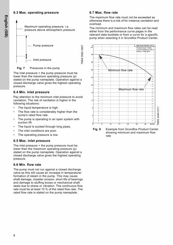
6.3 Max. operating pressure
Fig. 7 Pressures in the pump
The inlet pressure + the pump pressure must be lower than the maximum operating pressure (p) stated on the pump nameplate. Operation against a closed discharge valve gives the highest operating pressure.
6.4 Min. inlet pressure
Pay attention to the minimum inlet pressure to avoid cavitation. The risk of cavitation is higher in the following situations:
• The liquid temperature is high.
• The flow rate is considerably higher than the pump's rated flow rate.
• The pump is operating in an open system with suction lift.
• The liquid is sucked through long pipes.
• The inlet conditions are poor.
• The operating pressure is low.
6.5 Max. inlet pressure
The inlet pressure + the pump pressure must be lower than the maximum operating pressure (p) stated on the pump nameplate. Operation against a closed discharge valve gives the highest operating pressure.
6.6 Min. flow rate
The pump must not run against a closed discharge valve as this will cause an increase in temperature/formation of steam in the pump. This may cause shaft damage, impeller erosion, short life of bearings and damage to stuffing boxes or mechanical shaft seals due to stress or vibration. The continuous flow rate must be at least 10 % of the rated flow rate. The rated flow rate is stated on the pump nameplate.
6.7 Max. flow rate
The maximum flow rate must not be exceeded as otherwise there is a risk of for instance cavitation and overload.
The minimum and maximum flow rates can be read either from the performance curve pages in the relevant data booklets or from a curve for a specific pump when selecting it in Grundfos Product Center.
Fig. 8 Example from Grundfos Product Center showing minimum and maximum flow rate
TM
04
00
62
49
07
Inlet pressure
Pump pressure
Maximum operating pressure, i.e. pressure above atmospheric pressure
TM
05
24
44
511
1
Minimum flow rate
Maximum flow rate
En
glis
h (
GB
)
9
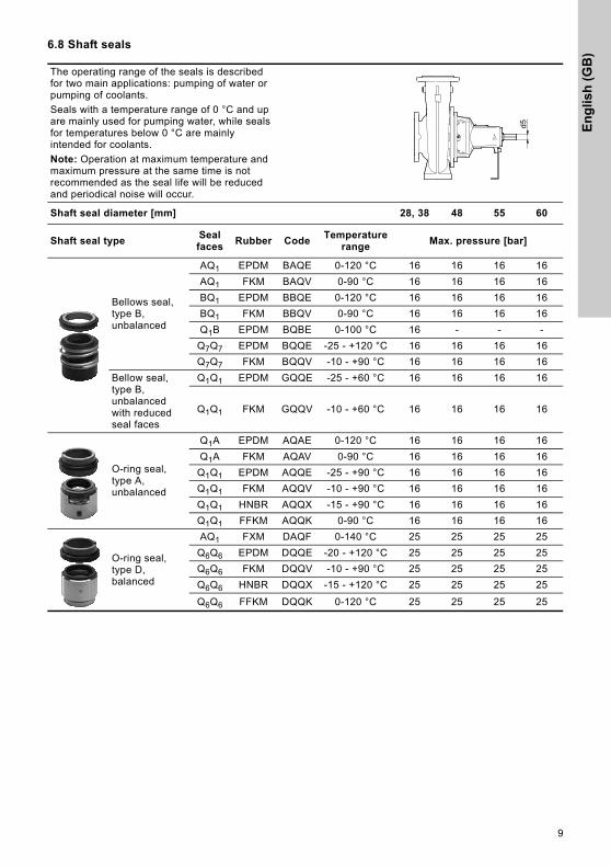
6.8 Shaft seals
The operating range of the seals is described for two main applications: pumping of water or pumping of coolants.
Seals with a temperature range of 0 °C and up are mainly used for pumping water, while seals for temperatures below 0 °C are mainly intended for coolants.
Note: Operation at maximum temperature and maximum pressure at the same time is not recommended as the seal life will be reduced and periodical noise will occur.
Shaft seal diameter [mm] 28, 38 48 55 60
Shaft seal typeSeal faces
Rubber CodeTemperature
rangeMax. pressure [bar]
Bellows seal, type B, unbalanced
AQ1 EPDM BAQE 0-120 °C 16 16 16 16
AQ1 FKM BAQV 0-90 °C 16 16 16 16
BQ1 EPDM BBQE 0-120 °C 16 16 16 16
BQ1 FKM BBQV 0-90 °C 16 16 16 16
Q1B EPDM BQBE 0-100 °C 16 - - -
Q7Q7 EPDM BQQE -25 - +120 °C 16 16 16 16
Q7Q7 FKM BQQV -10 - +90 °C 16 16 16 16
Bellow seal, type B, unbalanced with reduced seal faces
Q1Q1 EPDM GQQE -25 - +60 °C 16 16 16 16
Q1Q1 FKM GQQV -10 - +60 °C 16 16 16 16
O-ring seal, type A, unbalanced
Q1A EPDM AQAE 0-120 °C 16 16 16 16
Q1A FKM AQAV 0-90 °C 16 16 16 16
Q1Q1 EPDM AQQE -25 - +90 °C 16 16 16 16
Q1Q1 FKM AQQV -10 - +90 °C 16 16 16 16
Q1Q1 HNBR AQQX -15 - +90 °C 16 16 16 16
Q1Q1 FFKM AQQK 0-90 °C 16 16 16 16
O-ring seal, type D, balanced
AQ1 FXM DAQF 0-140 °C 25 25 25 25
Q6Q6 EPDM DQQE -20 - +120 °C 25 25 25 25
Q6Q6 FKM DQQV -10 - +90 °C 25 25 25 25
Q6Q6 HNBR DQQX -15 - +120 °C 25 25 25 25
Q6Q6 FFKM DQQK 0-120 °C 25 25 25 25

En
glish
(GB
)
10
7. Pump without motor
7.1 Mounting of motor on pump housing without feet
The pumps are supplied with a transport bracket protecting the shaft seal during transport. When you mount the motor, follow the instructions shown in these drawings.
TM
05
33
27
12
12
TM
03
39
06
12
12
1. Remove the coupling guard and loosen the set screws in the shaft.
2. Place the pump on the motor.
TM
03
39
07
12
12
TM
03
39
08
12
12
3. Fit and tighten the motor screws to the correct torque. See below.
4. Remove the nut, washer and transport bracket.
M8: 12 ± 2.4 Nm
M10: 25 ± 5 Nm
M12: 40 ± 8 Nm
M16: 100 ± 20 Nm
M20: 150 ± 30 Nm
M24: 200 ± 40 Nm

En
glis
h (
GB
)
11
TM
03
39
09
12
12
TM
03
39
10
12
12
5. Press down the threaded pipe to ensure that the shaft is in bottom position.
6. Remove the threaded pipe.
TM
03
39
09
12
12
TM
03
39
12
12
12
7. Apply Loctite 243 to the threads of the set screws. Tighten the set screws to the correct torque. See below.
8. Fit the coupling guard. Tighten the screws to the correct torque. See below.
M5: 6 ± 2 Nm M5 x 10 mm: 6 ± 2 Nm
M6: 8 ± 2 Nm
M8: 15 ± 3 Nm

En
glish
(GB
)
12
7.2 Mounting of motor on pump housing with feet
The pumps are supplied with a transport bracket protecting the shaft seal during transport. When you mount the motor, follow the instructions shown in these drawings.
TM
03
39
13
12
06
TM
03
39
05
12
06
1. Remove the coupling guard and loosen the set screws in the shaft.
2. Place the pump at the end of the motor and push the parts together.
TM
03
39
14
12
06
TM
03
39
15
12
06
3. Fit and tighten the motor screws to the correct torque. See below.
4. Remove the nut, washer and transport bracket.
M8: 12 ± 2.4 Nm
M10: 25 ± 5 Nm
M12: 40 ± 8 Nm
M16: 100 ± 20 Nm
M20: 150 ± 30 Nm
M24: 200 ± 40 Nm

En
glis
h (
GB
)
13
TM
03
39
16
12
06
TM
03
39
17
12
06
5. Press down the threaded pipe to ensure that the shaft is in bottom position.
6. Remove the threaded pipe.
TM
03
39
18
12
06
TM
03
39
19
12
06
7. Apply Loctite 243 to the threads of the set screws. Tighten the set screws to the correct torque. See below.
8. Fit the coupling guard. Tighten the screws to the correct torque. See below.
M5: 6 ± 2 Nm M5 x 10 mm: 6 ± 2 Nm
M6: 8 ± 2 Nm
M8: 15 ± 3 Nm

En
glish
(GB
)
14
8. Mechanical installation
8.1 Preparations before installation
The contractor must inspect the equipment on delivery and make sure that it is stored in such a way that corrosion and damage are avoided. If more than six months will pass before the equipment is put into operation, please consider applying a suitable corrosion inhibitor to the internal pump parts.
Ensure that the corrosion inhibitor used does not affect the rubber parts with which it comes into contact.
Ensure that the corrosion inhibitor can easily be removed.
To prevent water, dust, etc. from entering the pump, all openings must be kept covered until the pipes are fitted. The cost of dismantling the pump during startup to remove a foreign object can be very high.
Mechanical shaft seals are precision components. If the mechanical shaft seal of a recently installed pump fails, this will normally happen within the first few hours of operation. The main cause of such failures is improper installation of the shaft seals and/or mishandling of the pump during installation.
During transport, the pump must be fastened securely to prevent damage to the shaft and seal caused by excessive vibrations and knocks. The pump must not be lifted by means of the shaft.
8.2 Pump location
The pump should be sited in a well-ventilated, but frost-free location.
For inspection and repair, allow suitable clearances for pump or motor removal.
Vertical installation
• Pumps fitted with motors up to and including 4 kW require a 0.3 m clearance above the motor.
• Pumps fitted with motors of 5.5 kW and up require at least a 1 metre clearance above the motor to allow the use of lifting equipment.
Fig. 9 Clearance above the motor
Horizontal installation
• Pumps fitted with motors up to and including 4 kW require a 0.3 m clearance behind the motor.
• Pumps fitted with motors of 5.5 kW and up require a 0.3 m clearance behind the motor and at least a 1 metre clearance above the motor to allow the use of lifting equipment.
• NB pumps with base frame must have the same clearance as pumps with motors from 5.5 to 200 kW.
Fig. 10 Clearance behind the motor
Warning
When pumping hot liquids, care should be taken to ensure that persons cannot accidentally come into contact with hot surfaces.
TM
03
41
28
17
06
TM
03
41
27
17
06
0.3 m 1 m
0.25 - 4 kW 5.5 - 37 kW
0.3 m
0.25 - 4 kW
5.5 - 200 kW
1 m
0.3 m

En
glis
h (
GB
)
15
8.3 Connection
Arrows on the pump housing show the direction of flow of liquid through the pump.
The pumps can be installed with the motor/pump shaft in all positions between vertical and horizontal, but the motor must never fall below the horizontal plane.
Horizontal motors with feet must always be supported.
Fig. 11 Installation positions
It is advisable to fit isolating valves on either side of the pump as this makes it unnecessary to drain the system if the pump needs to be cleaned or repaired.
8.4 Foundation of NB, NBG pump without base frame
We recommend that you install the pump on a plane and rigid concrete foundation which is heavy enough to provide permanent support for the entire pump. The foundation must be capable of absorbing any vibration, normal strain or shock. As a rule of thumb, the weight of the concrete foundation should be 1.5 times the weight of the pump. The concrete foundation must have an absolutely level and even surface.
Place the pump on the foundation, and fasten it. See fig. 12.
Fig. 12 Foundation
The foundation length and width should always be 200 mm larger than the length and width of the pump. See fig. 12.
The mass of the foundation must be at least 1.5 times the total mass of the pump. The minimum height of the foundation (hf) can then be calculated:
The density () of concrete is usually taken as 2,200 kg/m3.
In installations where noise-less operation is particularly important, a foundation with a mass up to 5 times that of the pump is recommended. See also 8.7 Vibration dampening on page 20.
TM
03
41
26
17
06
Caution
The foundation/installation must be carried out in accordance with the following instructions. Non-compliance may result in functional faults which will damage the pump components!
0.25 - 37 kW 0.25 - 200 kW
TM
03
41
30
17
06
hf =mpump × 1.5
Lf × Bf × concrete

En
glish
(GB
)
16
8.5 Foundation of NB, NBG pump with base frame
This section applies only to 50 Hz pumps as base frames are not supplied for 60 Hz pumps.
We recommend that you install the pump on a plane and rigid concrete foundation which is heavy enough to provide permanent support for the entire pump. The foundation must be capable of absorbing any vibration, normal strain or shock. As a rule of thumb, the weight of the concrete foundation should be 1.5 times the weight of the pump.
The foundation should be 100 mm larger than the base frame on all four sides. See fig. 13.
Fig. 13 Foundation, X = min. 100 mm
The minimum height of the foundation (hf) can then be calculated:
The density () of concrete is usually taken as 2,200 kg/m3.
Place the pump on the foundation, and fasten it. The base frame must be supported under its entire area. See fig. 14.
Fig. 14 Correct foundation
Fig. 15 Incorrect foundation
Fig. 16 Base frame with pouring holes
It is important to prepare a good foundation prior to the installation of the pump.
NB, NBG pumps with base frame are always prepared for grouting (grouting anchors welded onto the base frame).
For NB, NBG pumps with 2-pole motors ≥ 55 kW, grouting of the base frame is mandatory in order to prevent vibration energy from the rotating motor and liquid flow to evolve.
Procedure
1. Preparing the foundation
2. Levelling of the base frame
3. Grouting.
TM
05
15
58
27
09
hf =mpump × 1.5
Lf × Bf × concrete
TM
05
15
59
27
09
TM
05
15
60
27
09
TM
05
15
61
27
09
P2 ≤ 45 kW P2 ≥ 55 kW
2-pole Grouting optional Grouting mandatory
4-pole Grouting optional
6-pole Grouting optional

En
glis
h (
GB
)
17
1: Preparing the foundation
We recommend the following procedure to ensure a good foundation.
2: Levelling of the base frame
Step Action Illustration
1
Use an approved, non-shrinking concrete. (Contact your concrete supplier for advice if any doubts.)Pour the foundation without interruptions to within 19-32 mm of the final level. Use vibrators to ensure that the concrete is evenly distributed. The top surface should be well scored and grooved before the concrete sets. This provides a bonding surface for the grout.
2
Embed foundation bolts in the concrete. Allow enough bolt length to reach through grout, shims, lower base frame, nuts and washers.
TM
03
01
90
47
07
3Let the foundation cure for several days before the base frame is levelled and grouted.
Step Action Illustration
1
Lift/jack up the base frame to the final level 19-32 mm above the concrete foundation, and support the base frame by means of blocks and shims both at the foundation bolts and midway between bolts.
TM
04
51
83
28
09
2 Level the base frame by adding or removing shims under the base frame.
TM
04
04
89
07
08
3
Tighten the foundation bolt nuts against the base frame. Make sure the piping can be aligned to the pump flanges without putting strain on pipes or flanges.
5-10
mm
•
•
•
••
••
•
•
•
••
•
•
•
•
•
•
•
•
•
•
•
•
•
•
•
•
•
•
•
•
•
•
•
•
•
••
••
•
•
•
•
•
•
•
•
•
••
••
•
•
•
•
••
•
••
•
•
•
••
••
•
•
•
•
•
•
•
•
•
•
•
•
•
•
•
•
•
•
•
•
•
•
•
•
•
•
•
•
•
••
•
•
•
•
•
•
•
•
•
•
••
•
•
•
•
•
•
•
•
•
•
•
•
•
•
•
•
•
•
•
•
•
•
••
•
•
•
•
•
•
•
•
•
•
•
•
•
•
•
•
•
•
••
•
•
• •
•
•
•
•
•
•
•
•
•
•
•
•
•
•
•
•
•
•
•
•
•
••
•
•
•
•
•
•
•
•
•
•
•
•
•
•
•
•
•
•
•
••
•
•
•
•
•
•
•
•
•
•
•
•
•
•
•
•
•
•
•
•
•
•
•
•
•
•
•
•
•
•
•
•
•
•
•
•
•
•
•
•
•
••
•
•
•
••
•
•
•
•
•••
••
•
•
•
•
•
•
•
•
•
•
•
•• •
•
•
•
•
•
•
•
••
•
•
•
•
•
•
•
•
•
•
•
•
•
•
•
•
•
•
•
•
•
•
•
•
•
•
•
•
•
•
•
•
•
•
•
•
•
••
•
•
•
•
••
•
•
•
•
•
•
•
•
•
•
•
•
Bolt lengthabove
base frame
Thicknessof base
frame
19-32 mmallowance
for grout
Base frame
Top of foundation is rough
Pipe sleeveLugWasher
Wedges and shims left in place

En
glish
(GB
)
18
3: Grouting
Grouting compensates for an uneven foundation, distributes the weight of the unit, dampens vibrations and prevents shifting. Use an approved, non-shrinking grout. If you have questions or doubts about the grouting, please contact an expert on grouting.
Step Action Illustration
1
Embed reinforcing steel bars into the foundation by means of 2K anchor adhesive glue.
The number of steel bars depends on the size of the base frame, but it is advisable to distribute a minimum of 20 bars evenly over the whole area of the base frame.The free end of the steel bar should be 2/3 the height of the base frame to ensure a proper grouting.
TM
04
04
90
07
08
- T
M0
4 0
49
1 0
70
8
2 Soak top of concrete foundation thoroughly, then remove surface water.
3 Ensure proper shuttering at both ends of the base frame.
TM
05
15
62
30
11
4
If necessary, check the levelling of the base frame again before grouting. Pour non-shrinking grout through the openings of the base frame until the space underneath the base frame has been filled completely.
Fill the formwork with grout up to the base frame top level.Allow the grout to dry thoroughly before attaching piping to the pump (24 hours is sufficient time with approved grouting procedure).
When the grout has thoroughly hardened, check the foundation bolt nuts, and tighten, if necessary.
Approximately two weeks after the grout has been poured, or when the grout has thoroughly dried, apply an oil-based paint to the exposed edges of the grout to prevent the grout from getting into contact with air and moisture. T
M0
3 2
94
6 4
70
7
Minimum 20 bars
Shuttering
5-10
mm
•
•
•
••
••
•
•
•
••
•
•
•
•
•
•
•
•
•
•
•
•
•
•
•
•
•
•
•
•
•
•
•
•
•
••
••
•
•
•
•
•
•
•
•
•
••
• •
•
•
•
•
•••
••
•
•
•
••
••
•
•
•
•
•
•
•
•
•
•
•
•
•
•
•
•
•
•
•
•
•
•
•
•
•
•
•
•
•
••
•
•
•
•
•
•
•
•
•
•
••
•
•
•
•
•
•
•
•
•
•
•
•
•
•
•
•
•
•
•
•
•
•
••
•
•
•
•
•
•
•
•
•
•
•
•
•
•
•
•
•
•
••
•
•
• •
•
•
•
•
•
•
•
•
•
•
•
•
•
•
•
•
•
•
•
•
•
• •
•
••
•
•
•
•
•
•
•
•
•
•
•
•
•
•
•
•
•
••
•
•
•
•
•
•
•
•
•
•
•
•
•
•
•
•
•
•
•
•
•
•
•
•
•
•
•
•
•
•
•
•
•
•
•
•
•
•
•
•
•
••
•
•
•
••
•
•
•
•
•••
••
•
•
•
•
•
•
•
•
•
•
•
• • •
•
•
•
•
•
•
•
••
•
•
•
•
•
•
•
•
•
•
•
•
•
•
•
•
•
•
•
•
•
•
•
•
•
•
•
•
•
•
•
•
•
•
•
•
•
••
•
•
•
•
••
•
•
•
•
•
•
•
•
•
•
•
•
Base frame
Grout
Levelling wedges or shims left in placeTop of foundation - rough
19-32mm grout
Formwork

En
glis
h (
GB
)
19
8.6 Pipework
8.6.1 Piping
When installing the pipes, make sure that the pump housing is not stressed by the pipework.
The suction and discharge pipes must be of an adequate size, taking the pump inlet pressure into account.
Install the pipes so that air locks are avoided, especially on the suction side of the pump.
Fig. 17 Pipelines
Fit isolating valves on either side of the pump to avoid having to drain the system if the pump needs to be cleaned or repaired.
Make sure the pipes are adequately supported as close to the pump as possible, both on the suction and the discharge side. The counter flanges should lie true against the pump flanges without being stressed as stress would cause damage to the pump.
Fig. 18 NB, NBG pump installation
8.6.2 Direct mounting in pipework
Pumps fitted with motors up to and including frame size 132 are suitable for direct mounting in supported pipework.
Fig. 19 Direct mounting in pipework
This type of installation does not allow the use of expansion joints.
8.6.3 Bypass
If there is any danger of the pump running against a closed discharge valve, a minimum liquid flow through the pump should be ensured by connecting a bypass or drain to the discharge pipe. The minimum flow rate must be at least 10 % of the maximum flow rate. The flow rate and head are stated on the pump nameplate.
TM
00
22
63
33
93
TM
05
33
11 1
112
TM
05
33
37
12
12
NoteTo ensure quiet operation, the pipes should be suspended from suitable pipe hangers.
Warning
The pump is not allowed to run against a closed valve as this will cause an increase in temperature/formation of steam in the pump which may cause damage to the pump.

En
glish
(GB
)
20
8.7 Vibration dampening
8.7.1 Elimination of noise and vibrations
In order to achieve optimum operation and minimum noise and vibration, consider vibration dampening of the pump. Generally, always consider this for pumps with motors of 11 kW and up. For motors of 90 kW and up vibration dampening should be considered mandatory. Smaller motor sizes, however, may also cause undesirable noise and vibration.
Noise and vibration are generated by the revolutions of the motor and pump and by the flow in pipes and fittings. The effect on the environment is subjective and depends on correct installation and the state of the rest of the system.
Elimination of noise and vibrations is best achieved by means of a concrete foundation, vibration dampers and expansion joints. See fig. 18.
8.7.2 Vibration dampers
To prevent the transmission of vibrations to buildings, we recommend isolating the pump foundation from building parts by means of vibration dampers.
The selection of the right vibration damper requires the following data:
• forces transmitted through the damper
• motor speed, taking speed control, if any, into consideration
• required dampening in % (suggested value is 70 %).
The selection of vibration damper differs from installation to installation. In certain cases, a wrong damper may increase the vibration level. Vibration dampers should therefore be sized by the supplier of the vibration dampers.
If you install the pump on a foundation with vibration dampers, always fit expansion joints on the pump flanges. This is important to prevent the pump from "hanging" in the flanges.
8.8 Expansion joints
Expansion joints provide these advantages:
• absorption of thermal expansion and contraction of pipework caused by variations in liquid temperature
• reduction of mechanical influences in connection with pressure surges in the pipework
• isolation of structure-borne noise in the pipework (only rubber bellows expansion joints).
The expansion joints should be fitted at a minimum distance of 1 to 1 1/2 pipe diameters (DN) away from the pump on the suction and the discharge side. This prevents turbulence in the joints, thus ensuring optimum suction conditions and minimum pressure loss on the discharge side. At flow velocities > 5 m/s, we recommend fitting larger expansion joints matching the pipework.
Figures 20 and 21 show examples of rubber bellows expansion joints with or without limiting rods.
Fig. 20 Rubber bellows expansion joint with limiting rods
Note
Do not install expansion joints to make up for inaccuracies in the pipework, such as centre displacement or misalignment of flanges.
TM
02
49
79
19
02

En
glis
h (
GB
)
21
Fig. 21 Rubber bellows expansion joint without limiting rods
Expansion joints with limiting rods can be used to reduce the effects of the expansion/contraction forces on the pipework. We always recommend expansion joints with limiting rods for flanges larger than DN 100.
Anchor the pipes in such a way that they do not stress the expansion joints and the pump. Follow the supplier’s instructions and pass them on to advisers or pipe installers.
Figure 22 shows an example of a metal bellows expansion joint with limiting rods.
Fig. 22 Metal bellows expansion joint with limiting rods
Due to the risk of rupture of the rubber bellows, metal bellows expansion joints may be preferred at temperatures above +100 °C combined with high pressure.
8.9 Measuring instruments
8.9.1 Pressure gauge and mano-vacuum gauge
To ensure continuous monitoring of the operation, we recommend installing a pressure gauge (on the discharge side) and a mano-vacuum gauge (on the suction side). The pressure gauge taps should only be opened for test purposes. The measuring range of the gauges should be 20 % above the maximum pump discharge pressure.
When measuring with pressure gauges on the pump flanges, it should be noted that a pressure gauge does not register dynamic pressure (velocity pressure). On all NB and NBG pumps, the diameters of the suction and discharge flanges are different which results in different flow velocities at the two flanges. Consequently, the pressure gauge on the discharge flange will not show the pressure stated in the technical documentation, but a value which may be up to 1.5 bar (approx. 15 metres) lower.
8.9.2 Ammeter
To check the motor load, we recommend connecting an ammeter.
TM
02
49
81
19
02
TM
02
49
80
19
02

En
glish
(GB
)
22
9. Flange forces and torques
Fig. 23 Flange forces and torquesT
M0
3 3
97
4 3
80
9
Grey cast ironDiameter
DN
Force [N] Torque [Nm]
Fy Fz Fx ΣF * My Mz Mx ΣM *
Horizontal pump, z-axis,
discharge port
32 298 368 315 578 263 298 385 560
40 350 438 385 683 315 368 455 665
50 473 578 525 910 350 403 490 718
65 595 735 648 1155 385 420 525 770
80 718 875 788 1383 403 455 560 823
100 945 1173 1050 1838 438 508 613 910
125 1120 1383 1243 2170 525 665 735 1068
150 1418 1750 1575 2748 613 718 875 1278
200 2600 2100 2095 4055 805 928 1138 1680
250 3340 2980 2700 5220 1260 1460 1780 2620
300 4000 3580 3220 6260 1720 1980 2420 3560
Horizontal pump, x-axis,
suction port
50 525 473 578 910 350 403 490 718
65 648 595 735 1155 385 420 525 770
80 788 718 875 1383 403 455 560 823
100 1050 945 1173 1838 438 508 613 910
125 1243 1120 1383 2170 525 665 735 1068
150 1575 1418 1750 2748 613 718 875 1278
200 2100 1890 2345 3658 805 928 1138 1680
250 2700 3340 2980 5220 1260 1460 1780 2620
300 3220 4000 3580 6260 1720 1980 2420 3560
350 3760 4660 4180 7300 2200 2540 3100 4560

En
glis
h (
GB
)
23
* ΣF and ΣM are the vector sums of the forces and torques.
If not all loads reach the maximum permissible value, one of the values is allowed to exceed the normal limit. Contact Grundfos for further information.
Stainless steel
Diameter DN
Force [N] Torque [Nm]
Fy Fz Fx ΣF * My Mz Mx ΣM *
Horizontal pump, z-axis,
discharge port
32 595 735 630 1155 525 595 770 1120
40 700 875 770 1365 630 735 910 1330
50 945 1155 1050 1820 700 805 980 1435
65 1190 1470 1295 2310 770 840 1050 1540
80 1435 1750 1575 2765 805 910 1120 1645
100 1890 2345 2100 3675 875 1015 1225 1820
125 2240 2765 2485 4340 1050 1330 1470 2135
150 2835 3500 3150 5495 1225 1435 1750 2555
Horizontal pump, x-axis,
suction port
50 1050 945 1155 1820 700 805 980 1435
65 1295 1190 1470 2310 770 840 1050 1540
80 1575 1435 1750 2765 805 910 1120 1645
100 2100 1890 2345 3675 875 1015 1225 1820
125 2485 2240 2765 4340 1050 1330 1470 2135
150 3150 2835 3500 5495 1225 1435 1750 2555
200 4200 3780 4690 7315 1610 1855 2275 3360
En
glish
(GB
)
24
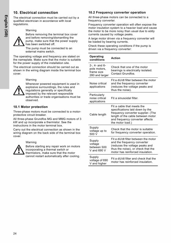
10. Electrical connectionThe electrical connection must be carried out by a qualified electrician in accordance with local regulations.
The operating voltage and frequency are stated on the nameplate. Make sure that the motor is suitable for the power supply of the installation site.
The electrical connection should be carried out as shown in the wiring diagram inside the terminal box cover.
10.1 Motor protection
Three-phase motors must be connected to a motor-protective circuit breaker.
All three-phase Grundfos MG and MMG motors of 3 kW and up incorporate a thermistor. See the instructions in the motor terminal box.
Carry out the electrical connection as shown in the wiring diagram on the back side of the terminal box cover.
10.2 Frequency converter operation
All three-phase motors can be connected to a frequency converter.
Frequency converter operation will often expose the motor insulation system to a heavier load and cause the motor to be more noisy than usual due to eddy currents caused by voltage peaks.
A large motor driven via a frequency converter will be loaded by bearing currents.
Check these operating conditions if the pump is driven via a frequency converter:
Warning
Before removing the terminal box cover and before removing/dismantling the pump, make sure that the power supply has been switched off.
The pump must be connected to an external mains switch.
Warning
Whenever powered equipment is used in explosive surroundings, the rules and regulations generally or specifically imposed by the relevant responsible authorities or trade organisations must be observed.
Warning
Before starting any repair work on motors incorporating a thermal switch or thermistors, make sure that the motor cannot restart automatically after cooling.
Operating conditions
Action
2-, 4- and 6-pole motors, frame size 280 and larger
Check that one of the motor bearings is electrically isolated. Contact Grundfos.
Noise critical applications
Fit a dU/dt filter between the motor and the frequency converter (reduces the voltage peaks and thus the noise).
Particularly noise critical applications
Fit a sinusoidal filter.
Cable length
Fit a cable that meets the specifications laid down by the frequency converter supplier. (The length of the cable between motor and frequency converter affects the motor load.)
Supply voltage up to 500 V
Check that the motor is suitable for frequency converter operation.
Supply voltage between 500 V and 690 V
Fit a dU/dt filter between the motor and the frequency converter (reduces the voltage peaks and thus the noise), or check that the motor has reinforced insulation.
Supply voltage of 690 V and higher
Fit a dU/dt filter and check that the motor has reinforced insulation.

En
glis
h (
GB
)
25
11. Commissioning and startup
11.1 General information
11.2 Commissioning
11.2.1 Flushing the pipe system
11.3 Priming
Closed systems or open systems where the liquid level is above the pump inlet
1. Close the discharge isolating valve and slowly open the isolating valve in the suction pipe. Both the pump and the suction pipe should be completely filled with liquid.
2. Slacken the priming plug (M) in order to vent the pump. Once liquid runs out, tighten the priming plug.
Suction operation with non-return valve
The suction pipe and the pump must be filled with liquid and vented before the pump is started.
1. Close the discharge isolating valve and slowly open the isolating valve in the suction pipe.
2. Remove the priming plug (M).
3. Pour liquid through the hole until the suction pipe and the pump are completely filled with liquid.
4. Fit the priming plug (M).
The suction pipe may be filled and vented via the priming plug. See fig. 24. Alternatively a priming device with funnel can be installed before the pump.
Open systems where the liquid level is below the pump inlet
1. If an isolating valve is fitted on the suction side of the pump, the valve must be fully open.
2. Close the discharge isolating valve and tighten the priming and drain plugs.
3. Connect a manual venting pump instead of a priming device (funnel).
4. A slide valve should be installed between the venting pump and the centrifugal pump in order to protect the venting pump against excessive pressure.
5. Once the slide valve at the manual venting pump has been opened, vent the suction pipe using short, rapid pump strokes until the liquid runs out on the discharge side.
6. Close the valve at the venting pump.
Fig. 24 Drain and priming plug
11.4 Checking the direction of rotation
The correct direction of rotation is shown by arrows on the pump housing. Seen from the pump end, the direction of rotation must be counter-clockwise. See fig. 24.
NoteDo not start the pump until it has been filled with liquid and vented.
Warning
When pumping drinking water, the pump should be flushed through with clean water before startup in order to remove any foreign matters such as preservatives, test liquid or grease.
Caution
The pump is not designed to pump liquids containing solid particles such as pipe debris and welding slag. Before starting up the pump, the pipe system must be thoroughly cleaned, flushed and filled with clean water.
The warranty does not cover any damage caused by flushing the pipe system by means of the pump.
Warning
Pay attention to the orientation of the priming hole to ensure that the escaping water does not cause personal injury or damage to the motor or other components.
In hot-liquid installations, pay special attention to the risk of personal injury caused by scalding hot liquid.
In cold-liquid installations, pay special attention to the risk of personal injury caused by the cold liquid.
E: Drain plugM: Priming plug
TM
03
39
35
12
06
Warning
The pump must be filled with liquid when checking the direction of rotation.

En
glish
(GB
)
26
11.5 Startup
Before starting the pump, completely open the isolating valve on the suction side of the pump and leave the isolating valve on the discharge side almost closed.
Start the pump.
Vent the pump during startup by loosening the air vent screw in the pump head/cover until a steady stream of liquid runs out of the vent hole.
When the pipework has been filled with liquid, slowly open the isolating valve on the discharge side until it is completely open.
Check the overload by measuring the motor current consumption and comparing the value with the nominal current stated on the motor nameplate. In case of overload, throttle the valve on the discharge side until the motor is no longer overloaded.
It is advisable always to measure the motor current consumption during startup.
11.6 Shaft seal run-in period
The seal faces are lubricated by the pumped liquid, meaning that there may be a certain amount of leakage from the shaft seal. When the pump is started for the first time, or when a new shaft seal is installed, a certain run-in period is required before the leakage is reduced to an acceptable level. The time required for this depends on the operating conditions, i.e. every time the operating conditions change, a new run-in period will be started.
Under normal conditions, the leaking liquid will evaporate. As a result, no leakage will be detected.
Liquids such as kerosene will not evaporate, and drops will be visible, but this is not a shaft seal failure.
11.7 Start/stop
11.8 Reference readings of monitoring equipment
We recommend taking initial readings of these parameters:
• inlet and outlet pressure (use pressure gauges).
The readings can be used as reference in case of abnormal operation.
Warning
Pay attention to the orientation of the vent hole to ensure that the escaping water does not cause personal injury or damage to the motor or other components.
In hot-liquid installations, pay special attention to the risk of personal injury caused by scalding hot liquid.
In cold-liquid installations, pay special attention to the risk of personal injury caused by the cold liquid.
Warning
If the pump is fitted with a motor with an output selected on the basis of a specific maximum flow rate, the motor may be overloaded if the differential pressure is lower than anticipated.
Note
At the moment of start, the input current of the pump motor is up to six times higher than the full-load current stated on the motor nameplate.
Frame size
Max. number of starts/hour
Number of poles
2 4 6
56-71 100 250 350
80-100 60 140 160
112-132 30 60 80
160-180 15 30 50
200-225 8 15 30
250-315 4 8 12

En
glis
h (
GB
)
27
12. Maintenance
12.1 Pump
The pump is maintenance-free.
12.2 Mechanical shaft seals
Mechanical shaft seals are maintenance-free, working almost without any leakages. If any considerable and increasing seepage occurs, the mechanical shaft seal should be checked immediately. If the sliding surfaces are damaged, the entire shaft seal should be replaced. Mechanical shaft seals should be treated with the greatest care.
12.3 Motor
Check the motor at regular intervals. It is important to keep the motor clean in order to ensure adequate ventilation. If the pump is installed in a dusty environment, it must he cleaned and checked regularly.
12.4 Lubrication
Motor bearings
Motors up to and including frame size 132 have maintenance-free, greased-for-life bearings.
Motors larger than frame size 132 should be greased according to the indications on the motor nameplate. Grease spills from the motor may occur.
Grease specifications: See section 12.4.1 Bearing grease.
12.4.1 Bearing grease
Lithium-based grease according to the following specifications must be used:
• NLGI class 2 or 3
• viscosity of basic oil: 70 to 150 cSt at +40 °C
• temperature range: -30 °C to +140 °C during continuous operation.
13. Periods of inactivity and frost protection
Pumps which are not being used during periods of frost should be drained to avoid damage.
Drain the pump by removing the drain plug (E). See fig. 24.
Do not tighten the priming plug or replace the drain plug until the pump is to be used again.
If the pump is to be drained prior to a long period of inactivity, inject a few drops of silicone oil on the shaft at the bearing bracket. This will prevent the shaft seal faces from seizing up.
14. Service
If Grundfos is requested to service such a pump, Grundfos must be contacted with details about the pumped liquid, etc. before the pump is returned for service. Otherwise Grundfos can refuse to accept the pump for service.
Possible costs of returning the pump are paid by the customer.
14.1 Service kits
Service kits for NB, NBG, see Grundfos Product Center in www. grundfos.com or Service Kit Catalogue.
15. Technical data
15.1 Electrical data
See the motor nameplate.
15.2 Sound pressure level
See table on page 30.
Warning
Before starting work on the product, switch off the power supply. Make sure that the power supply cannot be accidentally switched on.
Warning
Care must be taken to ensure that the escaping liquid does not cause personal injury or damage to the motor or other components.
In hot-liquid installations, pay special attention to the risk of personal injury caused by scalding hot liquid.
In cold-liquid installations, pay special attention to the risk of personal injury caused by the cold liquid.
Warning
If a pump has been used for a liquid which is injurious to health or toxic, the pump will be classified as contaminated.

En
glish
(GB
)
28
16. Fault finding
Warning
Before removing the terminal box cover and before removing/dismantling the pump, make sure that the power supply has been switched off and that it cannot be accidentally switched on again.
Fault Cause Remedy
1. Pump delivers no or too little liquid.
a) Wrong electrical connection (2 phases).
Check the electrical connection and remedy, if necessary.
b) Wrong direction of rotation. Interchange two phases of the power supply.
c) Air in suction pipe. Vent the suction pipe or the pump.
d) Counter-pressure too high. Set the duty point in accordance with the data sheet. Check the system for impurities.
e) Inlet pressure too low. Increase the liquid level on the suction side. Open the isolating valve in the suction pipe. Make sure that all the conditions in section 8.6 Pipework are complied with.
f) Suction pipe or impeller blocked by impurities.
Clean the suction pipe or pump.
g) Pump draws in air due to defective seal.
Check the pipeline seals, pump housing gaskets and shaft seals, and replace, if necessary.
h) Pump draws in air due to low liquid level.
Increase the liquid level on the suction side and keep it as constant as possible.
2. Motor-protective circuit breaker has tripped because the motor is overloaded.
a) Pump blocked by impurities. Clean the pump.
b) Pump running above rated duty point.
Set the duty point in accordance with the data sheet.
c) Density or viscosity of liquid higher than specified when ordering.
If less flow is sufficient, reduce the flow on the discharge side. Or fit a more powerful motor.
d) Motor-protective circuit breaker overload setting incorrect.
Check the setting of the motor-protective circuit breaker and replace, if necessary.
e) Motor runs on two phases. Check the electrical connection. Replace the fuse, if defective.
3. Pump makes too much noise.Pump runs unevenly and vibrates.
a) Inlet pressure too low (cavitation).
Increase the liquid level on the suction side. Open the isolating valve in the suction pipe. Make sure that all the conditions in section 8.6 Pipework are complied with.
b) Air in suction pipe or pump. Vent the suction pipe or the pump.
c) Counter-pressure lower than specified.
Set the duty point in accordance with the data sheet.
d) Pump draws in air due to low liquid level.
Increase the liquid level on the suction side and keep it as constant as possible.
e) Impeller out of balance (clogged impeller blades).
Clean and check the impeller.
f) Inner parts worn. Replace the defective parts.
g) Pump stressed by pipework (thus causing starting noise).
Mount the pump so that it is not stressed.Support the pipes.
h) Defective bearings. Replace the bearings.
i) Defective motor fan. Replace the fan.
j) Foreign bodies in pump. Clean the pump.
k) Frequency converter operation.
See section 10.2 Frequency converter operation.

En
glis
h (
GB
)
29
17. DisposalThis product or parts of it must be disposed of in an environmentally sound way:
1. Use the public or private waste collection service.
2. If this is not possible, contact the nearest Grundfos company or service workshop.
4. Leaking pump, connections or mechanical shaft seal.
a) Pump stressed by pipework (thus causing leaks in pump housing or at connections).
Mount the pump so that it is not stressed.Support the pipes.
b) Pump housing gaskets and gaskets at connections defective.
Replace pump housing gaskets or gaskets at connections.
c) Mechanical shaft seal dirty or stuck together.
Check and clean the mechanical shaft seal.
d) Mechanical shaft seal defective.
Replace the mechanical shaft seal.
e) Shaft surface defective. Replace the shaft.
5. Too high temperature in pump or motor.
a) Air in suction pipe or pump. Vent the suction pipe or the pump and replenish.
b) Inlet pressure too low. Increase the liquid level on the suction side. Open the isolating valve in the suction pipe. Make sure that all the conditions in section 8.6 Pipework are complied with.
c) Bearings lubricated with too little, too much or unsuitable lubricant.
Replenish, reduce or replace the lubricant.
d) Axial pressure too high. Check the relief holes of the impeller and the lock rings on the suction side.
e) Motor-protective circuit breaker defective or setting incorrect.
Check the setting of the motor-protective circuit breaker and replace, if necessary.
f) Motor overloaded. Reduce the flow rate.
Fault Cause Remedy

Ap
pe
nd
ix
30
Appendix 1
Sound pressure levels
The data in this table applies for pump including motor, (MG, MMG, Siemens and TECO motors).
The values stated are maximum sound pressure levels. Tolerences are according to ISO 4871.
50 Hz
2-pole: n = 2900 min-1
4-pole: n = 1450 min-1
6-pole: n = 970 min-1
60 Hz
2-pole: n = 3500 min-1
4-pole: n = 1750 min-1
6-pole: n = 1170 min-1
Motor [kW]
Maximum sound pressure level [dB(A)] - ISO 3743
Three-phase motors
2-pole 4-pole 6-pole
0.25 56 41 -
0.37 56 45 -
0.55 57 42 40
0.75 56 42 43
1.1 59 50 43
1.5 58 50 47
2.2 60 52 52
3 59 52 63
4 63 54 63
5.5 63 57 63
7.5 60 58 66
11 60 60 66
15 60 60 66
18.5 60 63 66
22 66 63 66
30 71 65 59
37 71 66 60
45 71 66 58
55 71 67 58
75 73 70 61
90 73 70 61
110 76 70 61
132 76 70 61
160 76 70 65
200 76 70 -
250 82 73 -
315 82 73 -
355 77 75 -
400 - 75
Motor [kW]
Maximum sound pressure level [dB(A)] - ISO 3743
Three-phase motor
2-pole 4-pole 6-pole
0.25 - - -
0.37 - - -
0.55 - - -
0.75 - - -
1.1 64 51 43
1.5 64 52 47
2.2 65 55 52
3 54 57 63
4 68 56 63
5.5 68 62 63
7.5 73 62 66
11 70 66 66
15 70 66 66
18.5 70 63 66
22 70 63 66
30 71 65 62
37 71 65 63
45 75 65 62
55 75 68 62
75 77 71 66
90 77 71 66
110 81 75 66
132 81 75 66
160 81 75 69
200 81 75 -
280 86 - -
288 - 77 -
353 86 - -
362 - 77 -
398 81
408 - 79 -
460 - 79 -

De
cla
rati
on
of
co
nfo
rmit
y
31
Declaration of conformity 2
GB: EC/EU declaration of conformityWe, Grundfos, declare under our sole responsibility that the products NB, NBG, to which the declaration below relates, are in conformity with the Council Directives listed below on the approximation of the laws of the EC/EU member states.
CN: 欧共体 / 欧盟符合性声明我们,格兰富,在我们的全权责任下声明,产品 NB、NBG,即该合格证所指之产品,符合欧共体 / 欧盟使其成员国法律趋于一致的以下理事会指令。
JP: EC/EU 適合宣言Grundfos は、その責任の下に、NB、NBG 製品が EC/EU 加盟諸国の法規に関連する、以下の評議会指令に適合していることを宣言します。
– Machinery Directive (2006/42/EC).Standard used: EN 809:1998 + A1:2009.
– Ecodesign Directive (2009/125/EC).Electric motors:Commission Regulation No. 640/2009.Applies only to three-phase Grundfos motors marked IE2 or IE3. See the motor nameplate.Standard used: EN 60034-30:2009.
– Ecodesign Directive (2009/125/EC).Water pumps:Commission Regulation No. 547/2012.Applies only to water pumps marked with the minimum efficiency index MEI. See the pump nameplate.
– ATEX Directive (2014/34/EU). Applies only to products with the ATEX mark on the nameplate.Standards used: EN 13463-1:2009, EN 13463-5:2011.Declaration of conformity and installation and operating instructions of the motor are enclosed.Notified body holding copy of technical file: DEKRA Certification B.V., Meander 1051/P.O. Box 5185, 6825 MJ ARNHEM / 6802 ED ARMHEM, The Netherlands.
This EC/EU declaration of conformity is only valid when published as part of the Grundfos installation and operating instructions (publication number 96658389 0818).
Suzhou, JiangSu Province, PRC6th February 2017
Ronnie HouDepartment Head of PD & Engineering, D&E China
Grundfos Holding A/SPoul Due Jensens Vej 7
8850 Bjerringbro, Denmark
Person authorised to compile the technical file and empowered to sign the EC/EU declaration of conformity.

Gru
nd
fos co
mp
anies
ArgentinaBombas GRUNDFOS de Argentina S.A.Ruta Panamericana km. 37.500 Centro Industrial Garin1619 Garín Pcia. de B.A.Phone: +54-3327 414 444Telefax: +54-3327 45 3190
AustraliaGRUNDFOS Pumps Pty. Ltd. P.O. Box 2040 Regency Park South Australia 5942 Phone: +61-8-8461-4611 Telefax: +61-8-8340 0155
AustriaGRUNDFOS Pumpen Vertrieb Ges.m.b.H.Grundfosstraße 2 A-5082 Grödig/Salzburg Tel.: +43-6246-883-0 Telefax: +43-6246-883-30
BelgiumN.V. GRUNDFOS Bellux S.A. Boomsesteenweg 81-83 B-2630 Aartselaar Tél.: +32-3-870 7300 Télécopie: +32-3-870 7301
BelarusПредставительство ГРУНДФОС в Минске220125, Минскул. Шафарнянская, 11, оф. 56, БЦ «Порт»Тел.: +7 (375 17) 286 39 72/73Факс: +7 (375 17) 286 39 71E-mail: [email protected]
Bosnia and HerzegovinaGRUNDFOS SarajevoZmaja od Bosne 7-7A,BH-71000 SarajevoPhone: +387 33 592 480Telefax: +387 33 590 465www.ba.grundfos.come-mail: [email protected]
BrazilBOMBAS GRUNDFOS DO BRASILAv. Humberto de Alencar Castelo Branco, 630CEP 09850 - 300São Bernardo do Campo - SPPhone: +55-11 4393 5533Telefax: +55-11 4343 5015
BulgariaGrundfos Bulgaria EOODSlatina DistrictIztochna Tangenta street no. 100BG - 1592 SofiaTel. +359 2 49 22 200Fax. +359 2 49 22 201email: [email protected]
CanadaGRUNDFOS Canada Inc. 2941 Brighton Road Oakville, Ontario L6H 6C9 Phone: +1-905 829 9533 Telefax: +1-905 829 9512
ChinaGRUNDFOS Pumps (Shanghai) Co. Ltd.10F The Hub, No. 33 Suhong RoadMinhang DistrictShanghai 201106PRCPhone: +86 21 612 252 22Telefax: +86 21 612 253 33
COLOMBIAGRUNDFOS Colombia S.A.S.Km 1.5 vía Siberia-Cota Conj. Potrero Chico,Parque Empresarial Arcos de Cota Bod. 1A.Cota, CundinamarcaPhone: +57(1)-2913444Telefax: +57(1)-8764586
CroatiaGRUNDFOS CROATIA d.o.o.Buzinski prilaz 38, BuzinHR-10010 ZagrebPhone: +385 1 6595 400 Telefax: +385 1 6595 499www.hr.grundfos.com
GRUNDFOS Sales Czechia and Slovakia s.r.o.Čajkovského 21779 00 OlomoucPhone: +420-585-716 111
DenmarkGRUNDFOS DK A/S Martin Bachs Vej 3 DK-8850 Bjerringbro Tlf.: +45-87 50 50 50 Telefax: +45-87 50 51 51 E-mail: [email protected]/DK
EstoniaGRUNDFOS Pumps Eesti OÜPeterburi tee 92G11415 TallinnTel: + 372 606 1690Fax: + 372 606 1691
FinlandOY GRUNDFOS Pumput AB Trukkikuja 1 FI-01360 Vantaa Phone: +358-(0) 207 889 500
FrancePompes GRUNDFOS Distribution S.A. Parc d’Activités de Chesnes 57, rue de Malacombe F-38290 St. Quentin Fallavier (Lyon) Tél.: +33-4 74 82 15 15 Télécopie: +33-4 74 94 10 51
GermanyGRUNDFOS GMBHSchlüterstr. 3340699 ErkrathTel.: +49-(0) 211 929 69-0 Telefax: +49-(0) 211 929 69-3799e-mail: [email protected] in Deutschland:e-mail: [email protected]
GreeceGRUNDFOS Hellas A.E.B.E. 20th km. Athinon-Markopoulou Av. P.O. Box 71 GR-19002 Peania Phone: +0030-210-66 83 400 Telefax: +0030-210-66 46 273
Hong KongGRUNDFOS Pumps (Hong Kong) Ltd. Unit 1, Ground floor Siu Wai Industrial Centre 29-33 Wing Hong Street & 68 King Lam Street, Cheung Sha Wan Kowloon Phone: +852-27861706 / 27861741 Telefax: +852-27858664
HungaryGRUNDFOS Hungária Kft.Tópark u. 8H-2045 Törökbálint, Phone: +36-23 511 110Telefax: +36-23 511 111
IndiaGRUNDFOS Pumps India Private Limited118 Old Mahabalipuram RoadThoraipakkamChennai 600 096Phone: +91-44 2496 6800
IndonesiaPT. GRUNDFOS POMPAGraha Intirub Lt. 2 & 3Jln. Cililitan Besar No.454. Makasar, Jakarta TimurID-Jakarta 13650Phone: +62 21-469-51900Telefax: +62 21-460 6910 / 460 6901
IrelandGRUNDFOS (Ireland) Ltd. Unit A, Merrywell Business ParkBallymount Road LowerDublin 12 Phone: +353-1-4089 800 Telefax: +353-1-4089 830
ItalyGRUNDFOS Pompe Italia S.r.l. Via Gran Sasso 4I-20060 Truccazzano (Milano)Tel.: +39-02-95838112 Telefax: +39-02-95309290 / 95838461
JapanGRUNDFOS Pumps K.K.1-2-3, Shin-Miyakoda, Kita-ku, Hamamatsu431-2103 JapanPhone: +81 53 428 4760Telefax: +81 53 428 5005
KoreaGRUNDFOS Pumps Korea Ltd.6th Floor, Aju Building 679-5Yeoksam-dong, Kangnam-ku, 135-916Seoul, KoreaPhone: +82-2-5317 600Telefax: +82-2-5633 725
LatviaSIA GRUNDFOS Pumps Latvia Deglava biznesa centrsAugusta Deglava ielā 60, LV-1035, Rīga,Tālr.: + 371 714 9640, 7 149 641Fakss: + 371 914 9646
LithuaniaGRUNDFOS Pumps UABSmolensko g. 6LT-03201 VilniusTel: + 370 52 395 430Fax: + 370 52 395 431

Gru
nd
fos
com
pan
ies
MalaysiaGRUNDFOS Pumps Sdn. Bhd.7 Jalan Peguam U1/25Glenmarie Industrial Park40150 Shah AlamSelangor Phone: +60-3-5569 2922Telefax: +60-3-5569 2866
MexicoBombas GRUNDFOS de México S.A. de C.V. Boulevard TLC No. 15Parque Industrial Stiva AeropuertoApodaca, N.L. 66600Phone: +52-81-8144 4000 Telefax: +52-81-8144 4010
NetherlandsGRUNDFOS NetherlandsVeluwezoom 351326 AE AlmerePostbus 220151302 CA ALMERE Tel.: +31-88-478 6336 Telefax: +31-88-478 6332E-mail: [email protected]
New ZealandGRUNDFOS Pumps NZ Ltd.17 Beatrice Tinsley CrescentNorth Harbour Industrial EstateAlbany, AucklandPhone: +64-9-415 3240Telefax: +64-9-415 3250
NorwayGRUNDFOS Pumper A/S Strømsveien 344 Postboks 235, Leirdal N-1011 Oslo Tlf.: +47-22 90 47 00 Telefax: +47-22 32 21 50
PolandGRUNDFOS Pompy Sp. z o.o.ul. Klonowa 23Baranowo k. PoznaniaPL-62-081 PrzeźmierowoTel: (+48-61) 650 13 00Fax: (+48-61) 650 13 50
PortugalBombas GRUNDFOS Portugal, S.A. Rua Calvet de Magalhães, 241Apartado 1079P-2770-153 Paço de ArcosTel.: +351-21-440 76 00Telefax: +351-21-440 76 90
RomaniaGRUNDFOS Pompe România SRLBd. Biruintei, nr 103 Pantelimon county IlfovPhone: +40 21 200 4100Telefax: +40 21 200 4101E-mail: [email protected]
RussiaООО Грундфос Россияул. Школьная, 39-41Москва, RU-109544, Russia Тел. (+7) 495 564-88-00 (495) 737-30-00Факс (+7) 495 564 8811E-mail [email protected]
Serbia Grundfos Srbija d.o.o.Omladinskih brigada 90b11070 Novi Beograd Phone: +381 11 2258 740Telefax: +381 11 2281 769www.rs.grundfos.com
SingaporeGRUNDFOS (Singapore) Pte. Ltd.25 Jalan Tukang Singapore 619264 Phone: +65-6681 9688 Telefax: +65-6681 9689
SlovakiaGRUNDFOS s.r.o.Prievozská 4D 821 09 BRATISLAVA Phona: +421 2 5020 1426sk.grundfos.com
SloveniaGRUNDFOS LJUBLJANA, d.o.o.Leskoškova 9e, 1122 LjubljanaPhone: +386 (0) 1 568 06 10Telefax: +386 (0)1 568 06 19E-mail: [email protected]
South AfricaGRUNDFOS (PTY) LTDCorner Mountjoy and George Allen RoadsWilbart Ext. 2Bedfordview 2008Phone: (+27) 11 579 4800Fax: (+27) 11 455 6066E-mail: [email protected]
SpainBombas GRUNDFOS España S.A. Camino de la Fuentecilla, s/n E-28110 Algete (Madrid) Tel.: +34-91-848 8800 Telefax: +34-91-628 0465
SwedenGRUNDFOS AB Box 333 (Lunnagårdsgatan 6) 431 24 Mölndal Tel.: +46 31 332 23 000Telefax: +46 31 331 94 60
SwitzerlandGRUNDFOS Pumpen AG Bruggacherstrasse 10 CH-8117 Fällanden/ZH Tel.: +41-44-806 8111 Telefax: +41-44-806 8115
TaiwanGRUNDFOS Pumps (Taiwan) Ltd. 7 Floor, 219 Min-Chuan Road Taichung, Taiwan, R.O.C. Phone: +886-4-2305 0868Telefax: +886-4-2305 0878
ThailandGRUNDFOS (Thailand) Ltd. 92 Chaloem Phrakiat Rama 9 Road,Dokmai, Pravej, Bangkok 10250Phone: +66-2-725 8999Telefax: +66-2-725 8998
TurkeyGRUNDFOS POMPA San. ve Tic. Ltd. Sti.Gebze Organize Sanayi Bölgesi Ihsan dede Caddesi,2. yol 200. Sokak No. 20441490 Gebze/ KocaeliPhone: +90 - 262-679 7979Telefax: +90 - 262-679 7905E-mail: [email protected]
UkraineБізнес Центр ЄвропаСтоличне шосе, 103м. Київ, 03131, Україна Телефон: (+38 044) 237 04 00 Факс.: (+38 044) 237 04 01E-mail: [email protected]
United Arab EmiratesGRUNDFOS Gulf DistributionP.O. Box 16768Jebel Ali Free ZoneDubaiPhone: +971 4 8815 166Telefax: +971 4 8815 136
United KingdomGRUNDFOS Pumps Ltd. Grovebury Road Leighton Buzzard/Beds. LU7 4TL Phone: +44-1525-850000 Telefax: +44-1525-850011
U.S.A.GRUNDFOS Pumps Corporation 17100 West 118th TerraceOlathe, Kansas 66061Phone: +1-913-227-3400 Telefax: +1-913-227-3500
UzbekistanGrundfos Tashkent, Uzbekistan The Representative Office of Grundfos Kazakhstan in Uzbekistan38a, Oybek street, TashkentТелефон: (+998) 71 150 3290 / 71 150 3291Факс: (+998) 71 150 3292
Addresses Revised 14.03.2018

www.grundfos.com
96658389 0818
ECM: 1240712 The
nam
e G
run
dfos
, the
Gru
ndf
os lo
go, a
nd b
e th
ink
inn
ova
te a
re r
egi
ster
ed t
rade
ma
rks
ow
ned
by
Gru
ndfo
s H
old
ing
A/S
or
Gru
ndf
os A
/S, D
enm
ark.
All
righ
ts r
ese
rved
wo
rldw
ide.
© C
opyr
ight
Gru
ndfo
s H
oldi
ng A
/S