Embed Size (px)
Citation preview
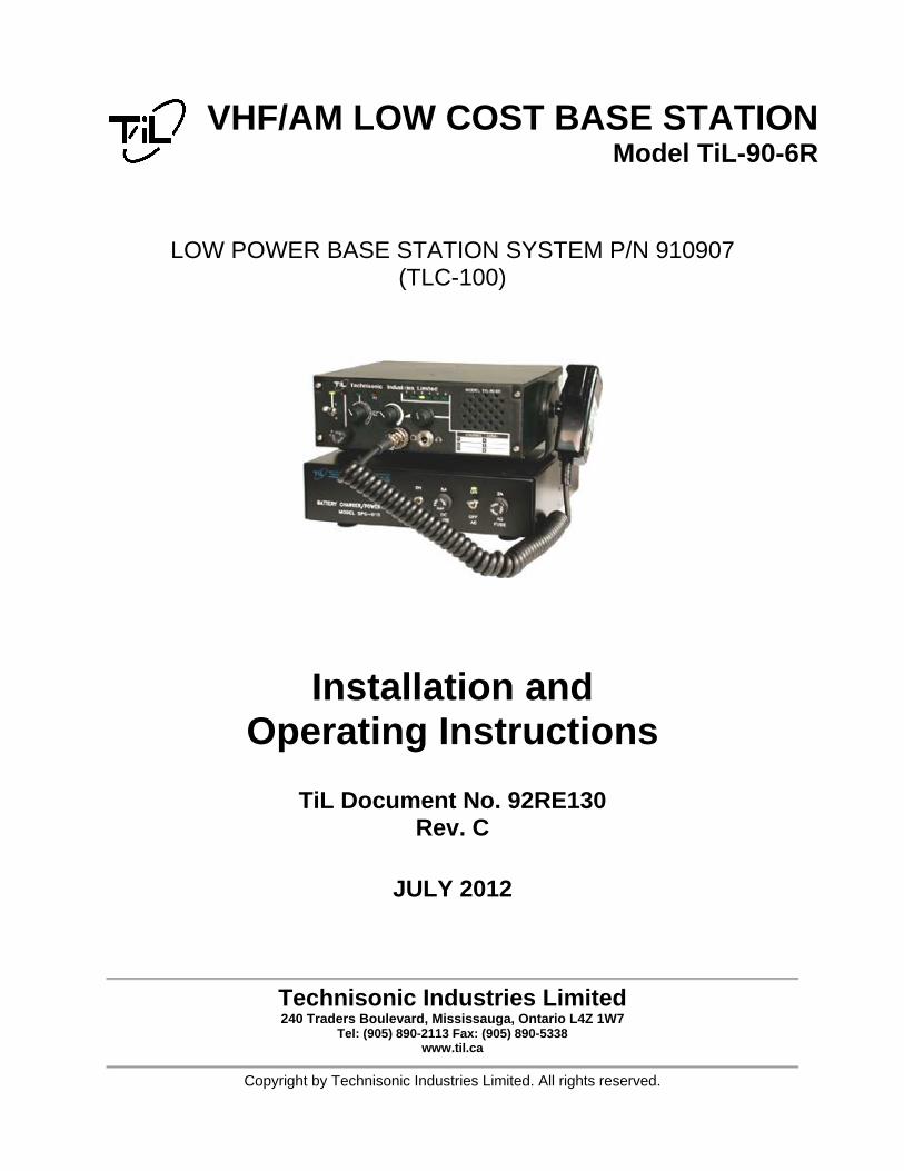
VHF/AM LOW COST BASE STATION Model TiL-90-6R
LOW POWER BASE STATION SYSTEM P/N 910907 (TLC-100)
Installation and Operating Instructions
TiL Document No. 92RE130 Rev. C
JULY 2012
Technisonic Industries Limited 240 Traders Boulevard, Mississauga, Ontario L4Z 1W7
Tel: (905) 890-2113 Fax: (905) 890-5338 www.til.ca
Copyright by Technisonic Industries Limited. All rights reserved.

ii
REVISION HISTORY [ 92RE130 ]
REV SECTION - PAGE - DESCRIPTION DATE Edited
by
n/c Original Document
A
B Global New Document Template (new file format) Title page changed, Headers/Footers added Added Revision page, Added Warranty page Remove reference of 91-DE from document. 4-7 Added note to §4.4 Channel Freq. Selection
referring to units built after Jan 2012 with a USB port and added Appendix A (TDP-90 for USB AM units) with Installation and Operating Instructions.
JAN 2012 FM
C Title Pg Simplify System description iii Updated FCC information including antenna and
FCC labeling instructions.
Simplify description under “Warning” Added "Low Cost" to Warranty Information
statement.
Global 7 Watt (7W) changed to Low Power 1-1 added NOTE: *Low Power description is found in
Table 4.1 under Power Output.
4-2 Revise Transmitter Characteristics for FCC and ICAN information
4.4 Para updated Appendix A Updated TDP90 to REV A JULY 2012 FM

iiii

iii
WARNING Do not make physical contact with antenna when transmitter is on. CAUTION ! STATIC SENSITIVE !
This unit contains static sensitive devices. Wear a grounded wrist strap and/or conductive gloves when handling printed circuit boards.
FCC COMPLIANCE INFORMATION This device complies with Part 15 of the FCC Rules. Operation is subject to the following two conditions: (1) this device may not cause harmful interference and (2) this device must accept any interference received, including interference that may cause undesired operation.
WARNING: For compliance with FCC RF Exposure Requirements the mobile transmitter antenna installation shall comply with the following two conditions:
1. The transmitter antenna gain shall not exceed 3 dBi. 2. The transmitter antenna is required to be located outside of a vehicle and kept at a separation distance of 90 cm
or more between the transmitter antenna of this device and person(s) during operation. NOTE: This equipment has been tested and found to comply with the limits for a Class A digital device, pursuant to Part 15 of the FCC Rules. These limits are designed to provide reasonable protection against harmful interference when the equipment is operated in a commercial environment. This equipment generates, uses, and can radiate radio frequency energy and, if not installed and used in accordance with the instruction manual, may cause harmful interference to radio communications. Operation of this equipment in a residential area is likely to cause harmful interference, in which case the user will be required to correct the interference at his/her own expense. FCC LABELING INFORMATION: When this device is permanently mounted in an enclosure where the FCC ID label can not be seen, another label must be placed on the outside of the enclosure stating ‘contains FCC ID: IMA90-6R’. WARRANTY INFORMATION The Low Cost Base Station, Model 90-6R is under warranty for one year from date of purchase. Failed units caused by defective parts, or workmanship should be returned to: Technisonic Industries Limited 240 Traders Boulevard Mississauga, Ontario L4Z 1W7 Tel: (905) 890-2113 Fax: (905) 890-5338

iv
TECHNISONIC INDUSTRIES LIMITED www.til.ca
TLC-100 90-6R Installation & Operating Instructions TiL 92RE130 Rev Cv
TABLE OF CONTENTS
SECTION TITLE PAGE
SECTION 1 GENERAL DESCRIPTION
1.1 INTRODUCTION ............................................................................................................... 1-1 1.2 DESCRIPTION .................................................................................................................. 1-1 1.2.1 Transceiver - Model Til-90-6R ........................................................................................... 1-1 1.2.2 Power Supply Modules - Model SPG-010, P/N 911008-1 ................................................ 1-1 1.2.3 Microphone P/N 861902 ................................................................................................... 1-2 1.2.4 Antenna ............................................................................................................................. 1-2 1.3 MODES OF OPERATION ................................................................................................. 1-2 1.3.1 Transmit/Receive Modes (Local Mode) ............................................................................ 1-2 1.3.2 Local/Remote Operation ................................................................................................... 1-3 1.3.3 AC and DC Operation ....................................................................................................... 1-3 1.4 TECHNICAL SUMMARY .................................................................................................. 1-3 SECTION 2 PREPARATION FOR USE AND STORAGE
2.1 INTRODUCTION ............................................................................................................... 2-1 2.2 DISASSEMBLY/ASSEMBLY ............................................................................................ 2-1 2.2.1 Remove/Replace Microphone ........................................................................................... 2-1 2.2.2 Remove/Replace Transceiver Unit ................................................................................... 2-1 2.3 LOUDSPEAKER, HEADPHONE INSTALLATION ............................................................ 2-2 2.3.1 External Loudspeaker ....................................................................................................... 2-2 2.3.2 Headset ............................................................................................................................. 2-2 2.4 OPERATIONAL CHECK ................................................................................................... 2-2 2.5 STORAGE ......................................................................................................................... 2-2 SECTION 3 GENERAL OPERATING INSTRUCTIONS
3.1 INTRODUCTION ............................................................................................................... 3-1 3.2 PREPARATION FOR USE ............................................................................................... 3-1 3.3 TRANSMITTER OPERATION .......................................................................................... 3-2 3.4 RECEIVER OPERATION .................................................................................................. 3-3 3.5 SWITCHING OFF ............................................................................................................. 3-3 3.6 BATTERY CHARGING ..................................................................................................... 3-4 SECTION 4 TRANSCEIVER SET UP and OPERATING INSTRUCTIONS
4.1 INTRODUCTION ............................................................................................................... 4-1 4.1.1 Transceiver Model TiL-90-6R P/N 861605-2 .................................................................... 4-1 4.1.2 Technical Summary .......................................................................................................... 4-1 4.2 OPERATOR'S SWITCHES, CONTROLS AND INDICATORS ......................................... 4-1 4.3 PREPARATION FOR USE ............................................................................................... 4-6 4.3.1 Operation in Transmit Mode .............................................................................................. 4-6 4.4 CHANNEL FREQUENCY SELECTION ............................................................................ 4-7 4.4.1 Introduction ........................................................................................................................ 4-7 4.4.2 Frequency Range .............................................................................................................. 4-7 4.4.3 Preparation ........................................................................................................................ 4-7 4.4.4 Preprogramming Channel Frequencies ............................................................................ 4-10 4.4.5 Installation of Module A5 ................................................................................................... 4-12 4.4.6 Operational Checks ........................................................................................................... 4-12 WARRANTY .......................................................................................................................................... Appendix A......TDP-90 Programming Software User’s Guide (for USB …) ........................................ A-1
TECHNISONIC INDUSTRIES LIMITED www.til.ca
TLC-100 90-6R Installation & Operating Instructions TiL 92RE130 Rev Cvi
LIST OF FIGURES
FIGURE TITLE PAGE 4.1 90-6R Low Cost Base Station Front Panel Layout ................................................................... 4-3 4.2 90-6R Low Cost Base Station Rear Panel Layout ................................................................... 4-3 4.3 Frequency Set-Memory Module A1 - Component Layout ........................................................ 4-11
LIST OF TABLES TABLE TITLE PAGE 1.1 Base Station Configurations ..................................................................................................... 1-1 1.2 Remote Control Connector Signals .......................................................................................... 1-3 4.1 Model Til-90-6R Transceiver Leading Particulars .................................................................... 4-2 4.2 Operators Switches, Controls and Indicators ........................................................................... 4-4 4.3 Frequency Selection MHz ........................................................................................................ 4-8 4.4 Frequency Selection KHz ......................................................................................................... 4-9
TECHNISONIC INDUSTRIES LIMITED www.til.ca
TLC-100 90-6R Installation & Operating Instructions TiL 92RE130 Rev C1-1
SECTION 1 - GENERAL DESCRIPTION
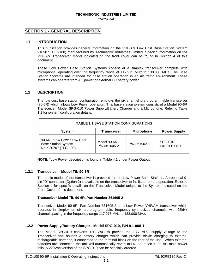
1.1 INTRODUCTION This publication provides general information on the VHF/AM Low Cost Base Station System 910907 (TLC-100) manufactured by Technisonic Industries Limited. Specific information on the VHF/AM Transceiver Model indicated on the front cover can be found in Section 4 of this document. These Low Power Base Station Systems consist of a simplex transceiver complete with microphone, operating over the frequency range of 117.975 MHz to 138.000 MHz. The Base Station Systems are intended for base station operation in an air traffic environment. These systems can operate from AC power or external DC battery power.
1.2 DESCRIPTION
The low cost base station configuration employs the six channel pre-programmable transceiver (90-6R) which allows Low Power operation. This base station system consists of a Model 90-6R Transceiver, Model SPG-010 Power Supply/Battery Charger and a Microphone. Refer to Table 1.1 for system configuration details.
TABLE 1.1 BASE STATION CONFIGURATIONS
System Transceiver Microphone Power Supply
90-6R, *Low Power Low Cost Base Station System No. 920707 (TLC-100)
Model 90-6R P/N 861605-2 P/N 861902-1 SPG-010
P/N 911008-1
NOTE: *Low Power description is found in Table 4.1 under Power Output.
1.2.1 Transceiver - Model TiL-90-6R
The basic model of the transceiver is provided for the Low Power Base Stations. An optional 9-pin "D" connector (Option 2) is available on the transceiver to facilitate remote operation. Refer to Section 4 for specific details on the Transceiver Model unique to the System indicated on the Front Cover of this document. Transceiver Model TiL-90-6R, Part Number 861605-2 Transceiver Model 90-6R, Part Number 861605-2, is a Low Power VHF/AM transceiver which operates in simplex on six pre-programmable, frequency synthesized channels, with 25kHz channel spacing in the frequency range 117.975 MHz to 138.000 MHz.
1.2.2 Power Supply/Battery Charger - Model SPG-010, P/N 911008-1
The Model SPG-010 converts 120 VAC to provide the 13.7 VDC supply voltage to the Transceiver and houses a battery charger which can provide trickle charging to external rechargeable batteries, if connected to the terminal block on the rear of the unit. When external batteries are connected the unit will automatically revert to DC operation if the AC main power fails. A 220Vac version of the SPG-010 can be specially ordered.
TECHNISONIC INDUSTRIES LIMITED www.til.ca
TLC-100 90-6R Installation & Operating Instructions TiL 92RE130 Rev C1-2
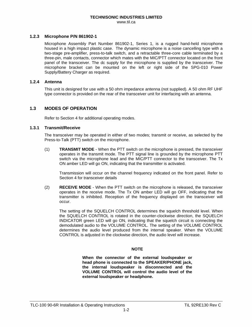
1.2.3 Microphone P/N 861902-1
Microphone Assembly Part Number 861902-1, Series 1, is a rugged hand-held microphone housed in a high impact plastic case. The dynamic microphone is a noise cancelling type with a two-stage pre-amplifier, press-to-talk switch, and a retractable three-core cable terminated by a three-pin, male contacts, connector which mates with the MIC/PTT connector located on the front panel of the transceiver. The dc supply for the microphone is supplied by the transceiver. The microphone bracket can be mounted on the left or right side of the SPG-010 Power Supply/Battery Charger as required.
1.2.4 Antenna
This unit is designed for use with a 50 ohm impedance antenna (not supplied). A 50 ohm RF UHF type connector is provided on the rear of the transceiver unit for interfacing with an antenna.
1.3 MODES OF OPERATION
Refer to Section 4 for additional operating modes.
1.3.1 Transmit/Receive
The transceiver may be operated in either of two modes; transmit or receive, as selected by the Press-to-Talk (PTT) switch on the microphone. (1) TRANSMIT MODE - When the PTT switch on the microphone is pressed, the transceiver
operates in the transmit mode. The PTT signal line is grounded by the microphone PTT switch via the microphone lead and the MIC/PTT connector to the transceiver. The Tx ON amber LED will go ON, indicating that the transmitter is activated. Transmission will occur on the channel frequency indicated on the front panel. Refer to Section 4 for transceiver details
(2) RECEIVE MODE - When the PTT switch on the microphone is released, the transceiver operates in the receive mode. The Tx ON amber LED will go OFF, indicating that the transmitter is inhibited. Reception of the frequency displayed on the transceiver will occur. The setting of the SQUELCH CONTROL determines the squelch threshold level. When the SQUELCH CONTROL is rotated in the counter-clockwise direction, the SQUELCH INDICATOR green LED will go ON, indicating that the squelch circuit is connecting the demodulated audio to the VOLUME CONTROL. The setting of the VOLUME CONTROL determines the audio level produced from the internal speaker. When the VOLUME CONTROL is adjusted in the clockwise direction, the audio level will increase.
NOTE
When the connector of the external loudspeaker or head phone is connected to the SPEAKER/PHONE jack, the internal loudspeaker is disconnected and the VOLUME CONTROL will control the audio level of the external loudspeaker or headphone.
TECHNISONIC INDUSTRIES LIMITED www.til.ca
TLC-100 90-6R Installation & Operating Instructions TiL 92RE130 Rev C1-3
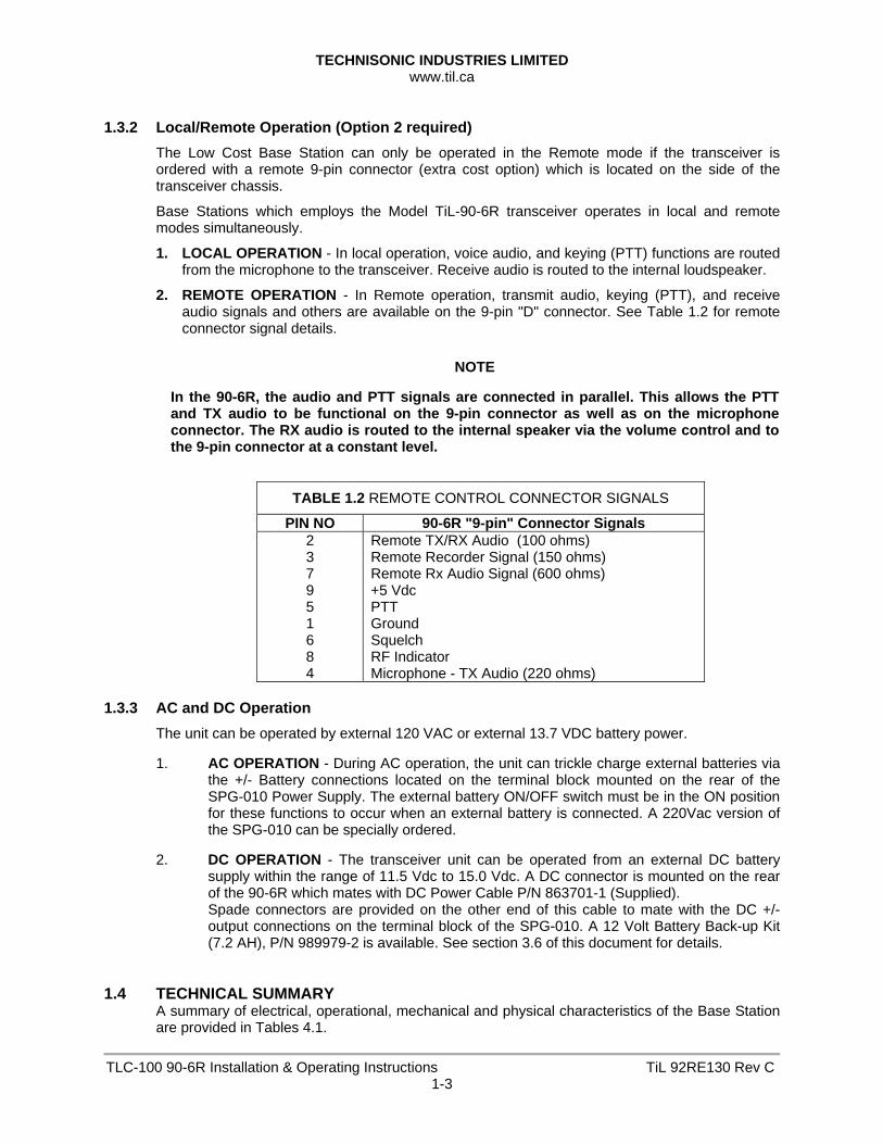
1.3.2 Local/Remote Operation (Option 2 required)
The Low Cost Base Station can only be operated in the Remote mode if the transceiver is ordered with a remote 9-pin connector (extra cost option) which is located on the side of the transceiver chassis.
Base Stations which employs the Model TiL-90-6R transceiver operates in local and remote modes simultaneously.
1. LOCAL OPERATION - In local operation, voice audio, and keying (PTT) functions are routed from the microphone to the transceiver. Receive audio is routed to the internal loudspeaker.
2. REMOTE OPERATION - In Remote operation, transmit audio, keying (PTT), and receive audio signals and others are available on the 9-pin "D" connector. See Table 1.2 for remote connector signal details.
NOTE
In the 90-6R, the audio and PTT signals are connected in parallel. This allows the PTT and TX audio to be functional on the 9-pin connector as well as on the microphone connector. The RX audio is routed to the internal speaker via the volume control and to the 9-pin connector at a constant level.
TABLE 1.2 REMOTE CONTROL CONNECTOR SIGNALS
PIN NO 90-6R "9-pin" Connector Signals 2 3 7 9 5 1 6 8 4
Remote TX/RX Audio (100 ohms) Remote Recorder Signal (150 ohms) Remote Rx Audio Signal (600 ohms) +5 Vdc PTT Ground Squelch RF Indicator Microphone - TX Audio (220 ohms)
1.3.3 AC and DC Operation
The unit can be operated by external 120 VAC or external 13.7 VDC battery power. 1. AC OPERATION - During AC operation, the unit can trickle charge external batteries via
the +/- Battery connections located on the terminal block mounted on the rear of the SPG-010 Power Supply. The external battery ON/OFF switch must be in the ON position for these functions to occur when an external battery is connected. A 220Vac version of the SPG-010 can be specially ordered.
2. DC OPERATION - The transceiver unit can be operated from an external DC battery
supply within the range of 11.5 Vdc to 15.0 Vdc. A DC connector is mounted on the rear of the 90-6R which mates with DC Power Cable P/N 863701-1 (Supplied). Spade connectors are provided on the other end of this cable to mate with the DC +/- output connections on the terminal block of the SPG-010. A 12 Volt Battery Back-up Kit (7.2 AH), P/N 989979-2 is available. See section 3.6 of this document for details.
1.4 TECHNICAL SUMMARY
A summary of electrical, operational, mechanical and physical characteristics of the Base Station are provided in Tables 4.1.

TECHNISONIC INDUSTRIES LIMITED www.til.ca
TLC-100 90-6R Installation & Operating Instructions TiL 92RE130 Rev C1-4
This page left intentionally blank.
TECHNISONIC INDUSTRIES LIMITED www.til.ca
TLC-100 90-6R Installation & Operating Instructions TiL 92RE130 Rev C2-1
SECTION 2 – PREPARATION FOR USE AND STORAGE 2.1 INTRODUCTION
This section provides the information required for use and storage of the low cost base station. Refer to Section 4 for Channel/Frequency configuration.
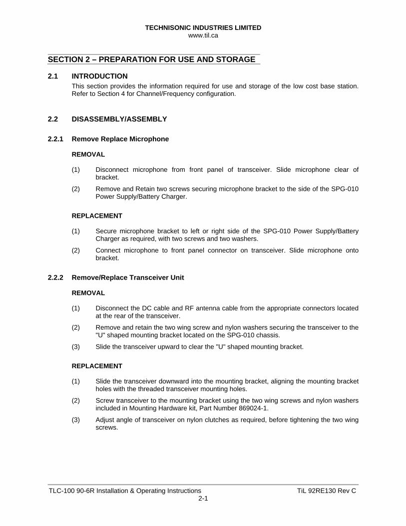
2.2 DISASSEMBLY/ASSEMBLY 2.2.1 Remove Replace Microphone
REMOVAL (1) Disconnect microphone from front panel of transceiver. Slide microphone clear of
bracket.
(2) Remove and Retain two screws securing microphone bracket to the side of the SPG-010 Power Supply/Battery Charger.
REPLACEMENT (1) Secure microphone bracket to left or right side of the SPG-010 Power Supply/Battery
Charger as required, with two screws and two washers.
(2) Connect microphone to front panel connector on transceiver. Slide microphone onto bracket.
2.2.2 Remove/Replace Transceiver Unit
REMOVAL (1) Disconnect the DC cable and RF antenna cable from the appropriate connectors located
at the rear of the transceiver.
(2) Remove and retain the two wing screw and nylon washers securing the transceiver to the "U" shaped mounting bracket located on the SPG-010 chassis.
(3) Slide the transceiver upward to clear the "U" shaped mounting bracket.
REPLACEMENT (1) Slide the transceiver downward into the mounting bracket, aligning the mounting bracket
holes with the threaded transceiver mounting holes.
(2) Screw transceiver to the mounting bracket using the two wing screws and nylon washers included in Mounting Hardware kit, Part Number 869024-1.
(3) Adjust angle of transceiver on nylon clutches as required, before tightening the two wing screws.

TECHNISONIC INDUSTRIES LIMITED www.til.ca
TLC-100 90-6R Installation & Operating Instructions TiL 92RE130 Rev C2-2
2.3 OPTIONAL LOUDSPEAKER, HEADPHONE INSTALLATION
Provision is made for connection of an external loudspeaker or headphone to the SPEAKER/PHONE jack of the transceiver, as shown in Figure 4.1.
2.3.1 External Loudspeaker
When an external loudspeaker is to be installed, an 8-ohm nominal impedance loudspeaker should be used. The loudspeaker cable should be terminated by a 1/4 in., 3-pole telephone plug (male), with the loudspeaker connected between tip and sleeve (ground). Insert the external loudspeaker connector into the SPEAKER/PHONE jack located on the front panel of the transceiver. When the external loudspeaker is connected to the transceiver SPEAKER/PHONE jack, the internal loudspeaker is automatically disconnected.
2.3.2 Headset
Headset impedance should be 150 to 600 ohms. The headset cable must terminate in a 1/4 in., 3-pole telephone plug (male), to mate with the SPEAKER/PHONE jack located on the front panel of the transceiver. The internal loudspeaker is automatically disconnected. Connect the headset as indicated below for receiver audio with or without transmit audio. (1) HEADSET WITHOUT TRANSMIT AUDIO - When receiver audio only without transmit
audio is required, the headset should be connected between the tip and sleeve (ground) of the telephone plug.
(2) HEADSET WITH TRANSMIT AUDIO - When receiver audio with transmit audio is required, the headset should be connected between the ring and sleeve (ground).
2.4 OPERATIONAL CHECK
Perform an operational check of the transceiver after all adjustments. Check each channel in use in both the transmit and receive modes of operation, using the Operating Instructions given in Section 3 of this document and the appropriate specified operating procedures during transmission.
2.5 STORAGE
To store for an extended period, store unit in a dry place, in the original shipping container.
TECHNISONIC INDUSTRIES LIMITED www.til.ca
TLC-100 90-6R Installation & Operating Instructions TiL 92RE130 Rev C3-1
SECTION 3 – GENERAL OPERATING INSTRUCTIONS 3.1 INTRODUCTION
This section covers general operating procedures applicable to all base station configurations. Set Up and Operating details for specific transceiver Model can be found in Section 4.
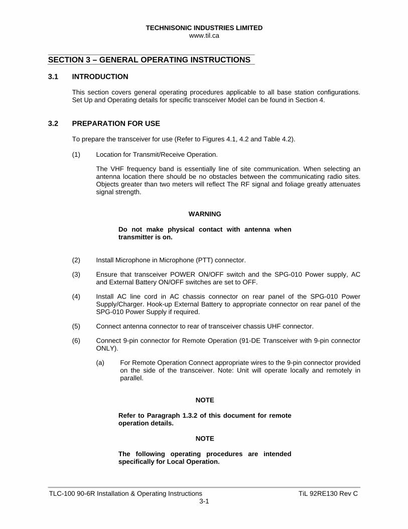
3.2 PREPARATION FOR USE
To prepare the transceiver for use (Refer to Figures 4.1, 4.2 and Table 4.2). (1) Location for Transmit/Receive Operation.
The VHF frequency band is essentially line of site communication. When selecting an antenna location there should be no obstacles between the communicating radio sites. Objects greater than two meters will reflect The RF signal and foliage greatly attenuates signal strength.
WARNING
Do not make physical contact with antenna when transmitter is on.
(2) Install Microphone in Microphone (PTT) connector.
(3) Ensure that transceiver POWER ON/OFF switch and the SPG-010 Power supply, AC and External Battery ON/OFF switches are set to OFF.
(4) Install AC line cord in AC chassis connector on rear panel of the SPG-010 Power Supply/Charger. Hook-up External Battery to appropriate connector on rear panel of the SPG-010 Power Supply if required.
(5) Connect antenna connector to rear of transceiver chassis UHF connector.
(6) Connect 9-pin connector for Remote Operation (91-DE Transceiver with 9-pin connector ONLY).
(a) For Remote Operation Connect appropriate wires to the 9-pin connector provided on the side of the transceiver. Note: Unit will operate locally and remotely in parallel.
NOTE
Refer to Paragraph 1.3.2 of this document for remote operation details.
NOTE
The following operating procedures are intended specifically for Local Operation.
TECHNISONIC INDUSTRIES LIMITED www.til.ca
TLC-100 90-6R Installation & Operating Instructions TiL 92RE130 Rev C3-2
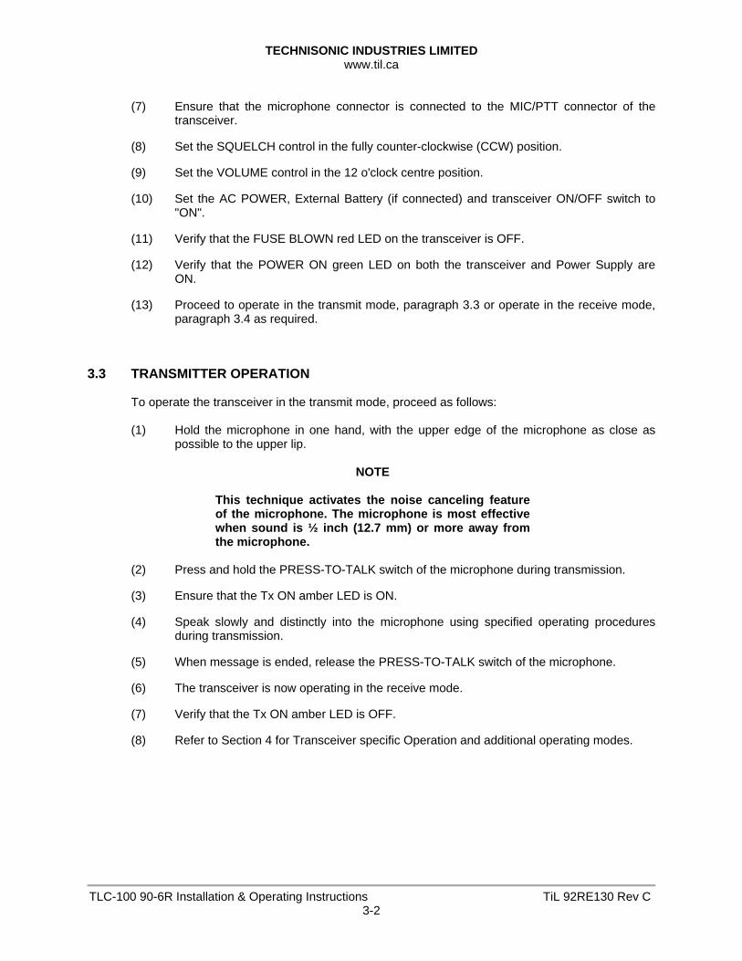
(7) Ensure that the microphone connector is connected to the MIC/PTT connector of the
transceiver.
(8) Set the SQUELCH control in the fully counter-clockwise (CCW) position.
(9) Set the VOLUME control in the 12 o'clock centre position.
(10) Set the AC POWER, External Battery (if connected) and transceiver ON/OFF switch to "ON".
(11) Verify that the FUSE BLOWN red LED on the transceiver is OFF.
(12) Verify that the POWER ON green LED on both the transceiver and Power Supply are ON.
(13) Proceed to operate in the transmit mode, paragraph 3.3 or operate in the receive mode, paragraph 3.4 as required.
3.3 TRANSMITTER OPERATION
To operate the transceiver in the transmit mode, proceed as follows: (1) Hold the microphone in one hand, with the upper edge of the microphone as close as
possible to the upper lip.
NOTE
This technique activates the noise canceling feature of the microphone. The microphone is most effective when sound is ½ inch (12.7 mm) or more away from the microphone.
(2) Press and hold the PRESS-TO-TALK switch of the microphone during transmission.
(3) Ensure that the Tx ON amber LED is ON.
(4) Speak slowly and distinctly into the microphone using specified operating procedures during transmission.
(5) When message is ended, release the PRESS-TO-TALK switch of the microphone.
(6) The transceiver is now operating in the receive mode.
(7) Verify that the Tx ON amber LED is OFF.
(8) Refer to Section 4 for Transceiver specific Operation and additional operating modes.

TECHNISONIC INDUSTRIES LIMITED www.til.ca
TLC-100 90-6R Installation & Operating Instructions TiL 92RE130 Rev C3-3
3.4 RECEIVER OPERATION
To operate the transceiver in the receive mode, proceed as follows: (1) Ensure that the PRESS-TO-TALK switch on the microphone is NOT depressed, and
verify that the Tx ON amber LED is OFF.
(2) Verify that the correct operating frequency is indicated on the front panel. Refer to Section 4 for Channel/Frequency selection.
(3) Adjust the SQUELCH control to suit local reception conditions. When the SQUELCH control is rotated in the counter-clockwise direction, the SQUELCH indicator green LED will switch to ON, indicating that the squelch circuit is connecting the demodulated audio output to the VOLUME control.
Further adjustment of the SQUELCH control determines the squelch setting.
(4) The VOLUME control can then be adjusted in a clockwise direction to increase the audio level, or in a counter-clockwise direction to decrease the audio level which can be heard on the internal loudspeaker.
NOTE
When an external loudspeaker or headset is connected to the SPEAKER/PHONE jack of the transceiver, the internal loudspeaker is automatically disconnected. The VOLUME control will now control the audio level applied to the external loudspeaker or headset, as applicable.
(5) Refer to Section 4 for transceiver specific operating modes.
3.5 SWITCHING OFF
To switch off the Low Cost Base Station: (1) Set the POWER ON/OFF on transceiver to switch to OFF.
(2) Verify that all indicator LED's on the front panel are OFF.
(3) Set the External Battery ON/OFF switch on the SPG-O10 Power Supply to OFF.
(4) Set the AC ON/OFF Power Switch on the SPG-010 Power Supply/Battery Charger to the OFF position.
TECHNISONIC INDUSTRIES LIMITED www.til.ca
TLC-100 90-6R Installation & Operating Instructions TiL 92RE130 Rev C3-4
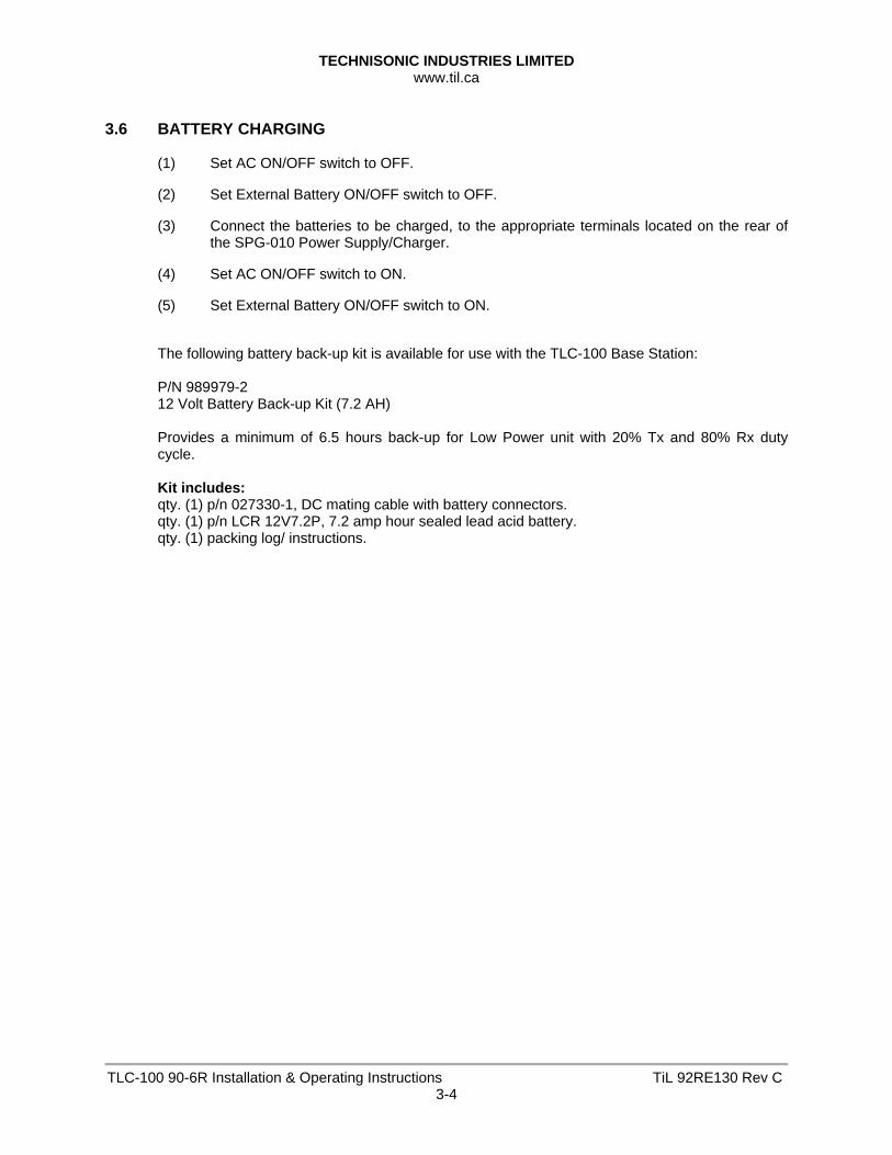
3.6 BATTERY CHARGING
(1) Set AC ON/OFF switch to OFF.
(2) Set External Battery ON/OFF switch to OFF.
(3) Connect the batteries to be charged, to the appropriate terminals located on the rear of the SPG-010 Power Supply/Charger.
(4) Set AC ON/OFF switch to ON.
(5) Set External Battery ON/OFF switch to ON.
The following battery back-up kit is available for use with the TLC-100 Base Station: P/N 989979-2 12 Volt Battery Back-up Kit (7.2 AH) Provides a minimum of 6.5 hours back-up for Low Power unit with 20% Tx and 80% Rx duty cycle. Kit includes: qty. (1) p/n 027330-1, DC mating cable with battery connectors. qty. (1) p/n LCR 12V7.2P, 7.2 amp hour sealed lead acid battery. qty. (1) packing log/ instructions.
TECHNISONIC INDUSTRIES LIMITED www.til.ca
TLC-100 90-6R Installation & Operating Instructions TiL 92RE130 Rev C4-1
SECTION 4 – OPERATING INSTRUCTIONS 4.1 INTRODUCTION 4.1.1 Transceiver Model TiL-90-6R, P/N 861605-2
The Transceiver is a frequency synthesised VHF/AM transceiver operating over the entire band of 117.975 to 138.000 MHz in 25 kHz steps. The transceiver can be pre-programmed with six user selected frequency channels. This section includes a functional description of each switch, control, indicator and connector located on the front and rear panels of the Low Cost Base Station, including the PRESS-TO-TALK switch located on the microphone. Operating instructions for transmit/receive are also included.
4.1.2 TECHNICAL SUMMARY
A summary of electrical, operational, mechanical and physical characteristics of the transceiver is provided in Table 4.1.
4.2 OPERATOR'S SWITCHES, CONTROLS AND INDICATORS
A view of the front and rear panels of the Low Cost Base Station is given in Figure 4.1 and Figure 4.2. A functional description of each of the operator's switches, controls and indicators, and the microphone PRESS-TO-TALK switch, is given in Table 4.2, Operator's Switches, Controls and Indicators.
TECHNISONIC INDUSTRIES LIMITED www.til.ca
TLC-100 90-6R Installation & Operating Instructions TiL 92RE130 Rev C4-2
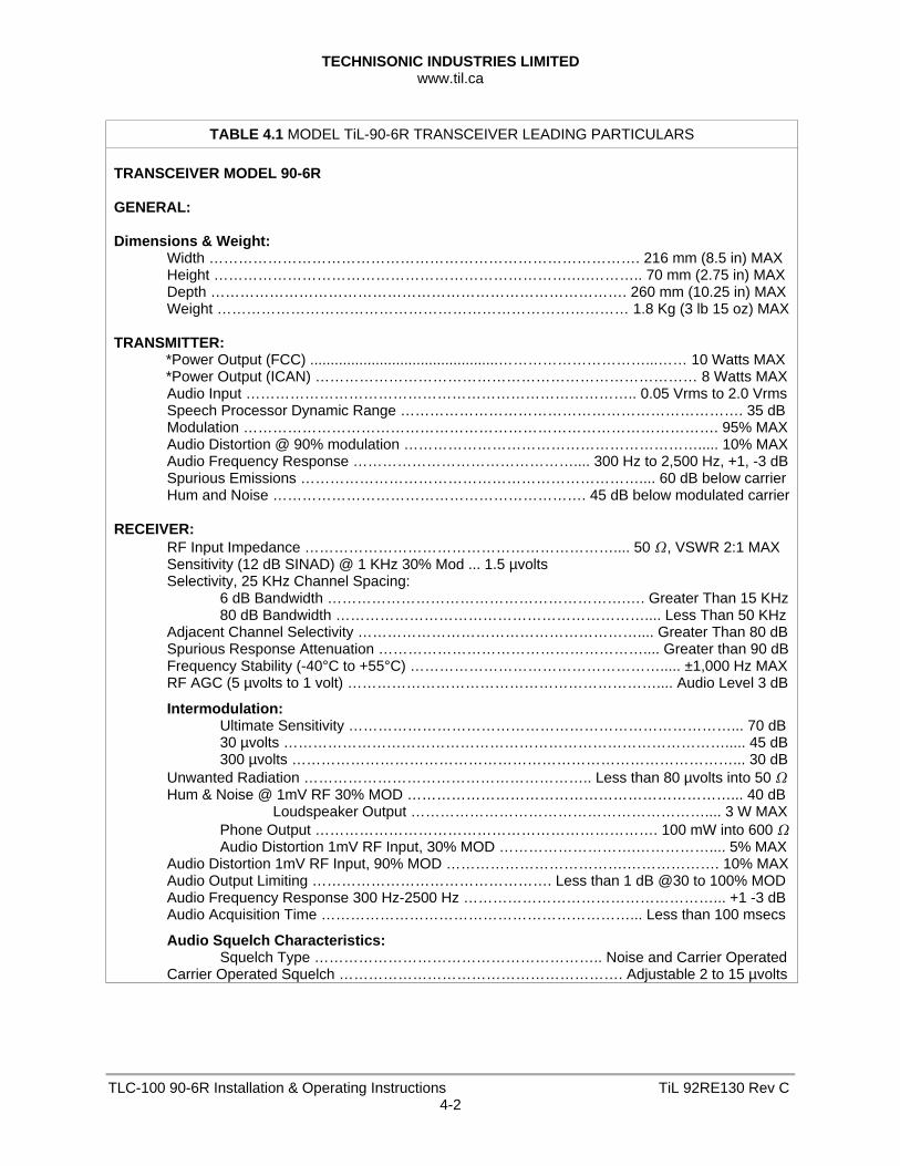
TABLE 4.1 MODEL TiL-90-6R TRANSCEIVER LEADING PARTICULARS
TRANSCEIVER MODEL 90-6R GENERAL: Dimensions & Weight: Width ……………………………………………………………………………. 216 mm (8.5 in) MAX Height ……………………………………………………………….….……….. 70 mm (2.75 in) MAX Depth …………………………………………………………………………. 260 mm (10.25 in) MAX Weight ………………………………………………………………………… 1.8 Kg (3 lb 15 oz) MAX TRANSMITTER:
*Power Output (FCC) ..............................................…………………………...…… 10 Watts MAX *Power Output (ICAN) …………………………………………………………………… 8 Watts MAX
Audio Input …………………………………………………………………….. 0.05 Vrms to 2.0 Vrms Speech Processor Dynamic Range ……………………………………………………………. 35 dB Modulation ……………………………………………………………………………………. 95% MAX Audio Distortion @ 90% modulation ……………………………………………………..... 10% MAX Audio Frequency Response ……………………………………….... 300 Hz to 2,500 Hz, +1, -3 dB Spurious Emissions …………………………………………………………….... 60 dB below carrier Hum and Noise ………………………………………………………. 45 dB below modulated carrier RECEIVER: RF Input Impedance ……………………………………………………….... 50 , VSWR 2:1 MAX Sensitivity (12 dB SINAD) @ 1 KHz 30% Mod ... 1.5 µvolts Selectivity, 25 KHz Channel Spacing: 6 dB Bandwidth …………………………………………………….…. Greater Than 15 KHz 80 dB Bandwidth ……………………………………………………….... Less Than 50 KHz Adjacent Channel Selectivity ………………………………………………….... Greater Than 80 dB Spurious Response Attenuation ……………………………………………….... Greater than 90 dB Frequency Stability (-40°C to +55°C) ……………………………………………..... ±1,000 Hz MAX RF AGC (5 µvolts to 1 volt) ……………………………………………………….... Audio Level 3 dB
Intermodulation: Ultimate Sensitivity ……………………………………………………………………... 70 dB 30 µvolts ………………………………………………………………………………..... 45 dB 300 µvolts ………………………………………………………………………………... 30 dB Unwanted Radiation ………………………………………………….. Less than 80 µvolts into 50 Hum & Noise @ 1mV RF 30% MOD …………………………………………………………... 40 dB Loudspeaker Output …………………………………………………….... 3 W MAX Phone Output ……………………………………………………………. 100 mW into 600 Audio Distortion 1mV RF Input, 30% MOD ……………………….…………….... 5% MAX Audio Distortion 1mV RF Input, 90% MOD ……………………………….………………. 10% MAX Audio Output Limiting …………………………………………. Less than 1 dB @30 to 100% MOD Audio Frequency Response 300 Hz-2500 Hz ……………………………………………... +1 -3 dB Audio Acquisition Time ………………………………………………………... Less than 100 msecs
Audio Squelch Characteristics: Squelch Type ………………………………………………….. Noise and Carrier Operated Carrier Operated Squelch …………………………………………………. Adjustable 2 to 15 µvolts
TECHNISONIC INDUSTRIES LIMITED www.til.ca
TLC-100 90-6R Installation & Operating Instructions TiL 92RE130 Rev C4-3
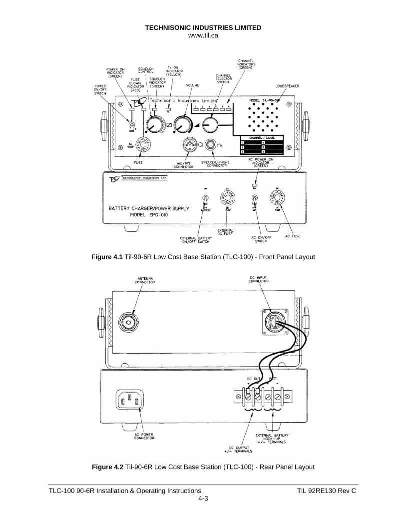
Figure 4.1 Til-90-6R Low Cost Base Station (TLC-100) - Front Panel Layout
Figure 4.2 Til-90-6R Low Cost Base Station (TLC-100) - Rear Panel Layout
TECHNISONIC INDUSTRIES LIMITED www.til.ca
TLC-100 90-6R Installation & Operating Instructions TiL 92RE130 Rev C4-4
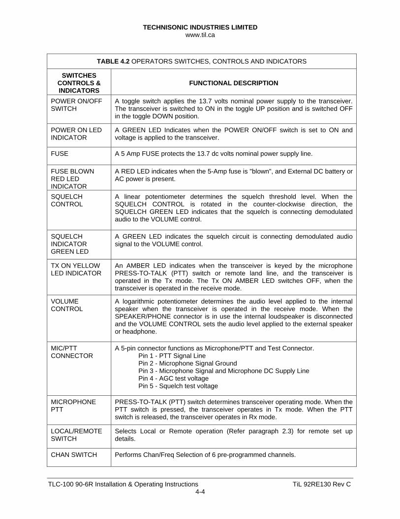
TABLE 4.2 OPERATORS SWITCHES, CONTROLS AND INDICATORS
SWITCHES CONTROLS & INDICATORS
FUNCTIONAL DESCRIPTION
POWER ON/OFF SWITCH
A toggle switch applies the 13.7 volts nominal power supply to the transceiver. The transceiver is switched to ON in the toggle UP position and is switched OFF in the toggle DOWN position.
POWER ON LED INDICATOR
A GREEN LED Indicates when the POWER ON/OFF switch is set to ON and voltage is applied to the transceiver.
FUSE A 5 Amp FUSE protects the 13.7 dc volts nominal power supply line.
FUSE BLOWN RED LED INDICATOR
A RED LED indicates when the 5-Amp fuse is "blown", and External DC battery or AC power is present.
SQUELCH CONTROL
A linear potentiometer determines the squelch threshold level. When the SQUELCH CONTROL is rotated in the counter-clockwise direction, the SQUELCH GREEN LED indicates that the squelch is connecting demodulated audio to the VOLUME control.
SQUELCH INDICATOR GREEN LED
A GREEN LED indicates the squelch circuit is connecting demodulated audio signal to the VOLUME control.
TX ON YELLOW LED INDICATOR
An AMBER LED indicates when the transceiver is keyed by the microphone PRESS-TO-TALK (PTT) switch or remote land line, and the transceiver is operated in the Tx mode. The Tx ON AMBER LED switches OFF, when the transceiver is operated in the receive mode.
VOLUME CONTROL
A logarithmic potentiometer determines the audio level applied to the internal speaker when the transceiver is operated in the receive mode. When the SPEAKER/PHONE connector is in use the internal loudspeaker is disconnected and the VOLUME CONTROL sets the audio level applied to the external speaker or headphone.
MIC/PTT CONNECTOR
A 5-pin connector functions as Microphone/PTT and Test Connector. Pin 1 - PTT Signal Line Pin 2 - Microphone Signal Ground Pin 3 - Microphone Signal and Microphone DC Supply Line Pin 4 - AGC test voltage Pin 5 - Squelch test voltage
MICROPHONE PTT
PRESS-TO-TALK (PTT) switch determines transceiver operating mode. When the PTT switch is pressed, the transceiver operates in Tx mode. When the PTT switch is released, the transceiver operates in Rx mode.
LOCAL/REMOTE SWITCH
Selects Local or Remote operation (Refer paragraph 2.3) for remote set up details.
CHAN SWITCH Performs Chan/Freq Selection of 6 pre-programmed channels.

TECHNISONIC INDUSTRIES LIMITED www.til.ca
TLC-100 90-6R Installation & Operating Instructions TiL 92RE130 Rev C4-5
TABLE 4.2 OPERATORS SWITCHES, CONTROLS AND INDICATORS
(Continued)
SWITCHES CONTROLS & INDICATORS
FUNCTIONAL DESCRIPTION
CHAN LABEL Indicates the Frequencies programmed for each channel.
CHANNEL LED's Six GREEN LED numbered 1 through 6 indicate the channel selected by the Channel Selector Switch.
LOUDSPEAKER An 8-ohm internal speaker reproduces the receiver audio output. The audio line is disconnected from the internal loudspeaker when the transceiver is operated in Tx mode or when the SPEAKER/PHONE connector is in use.
SPEAKER/ PHONE CONNECTOR
A 3-pole connector provides interconnection to either an external loudspeaker or headphone. When in use, the internal speaker is disconnected and the VOLUME control sets the audio level applied to the external speaker or headphone.
AC SWITCH A single pole switch applies AC power to the Model SPG-010 Power Supply/Charger.
AC POWER ON LED INDICATOR
A GREED LED indicates when AC power is applied to the SPG-010 and the AC POWER SWITCH is set to ON. Also indicates that the Model SPG-010 Power Supply is functioning.
AC FUSE A 2.5 Amp fuse protects the Base Station power supply from internal short circuit or transceiver short circuit.
EXTERNAL DC FUSE
A 5 Amp fuse protects the external batteries when connected.
External Battery ON/OFF Switch
A toggle switch allows external batteries (when connected) to be switched in or out of the circuit. Switch should be in the ON position to trickle charge external batteries when connected. DC Battery power will be automatically selected should AC power fail. Switch should be in OFF position if external batteries are not connected or if transceiver is operating with batteries that are deeply discharged or that have a defective cell.
*TERMINAL blk Terminal Block with DC output and external battery, +/- connections.
*AC POWER CONNECTOR
3 Prong AC Connector for use with AC Power Cord P/N 927002-1.
**REMOTE CONNECTOR
9 Pin "D" type connector (Optional) provides signals required for remote operation. Refer to Table 1-2 for connector details.
*EXTERNAL DC CONNECTOR
Transceiver chassis mounted connector provides for connection to SPG-010, terminal block. Mating DC power connector provided.
* Denotes items located on rear panel. ** Item not shown, located on side of the transceiver chassis, if ordered.
TECHNISONIC INDUSTRIES LIMITED www.til.ca
TLC-100 90-6R Installation & Operating Instructions TiL 92RE130 Rev C4-6
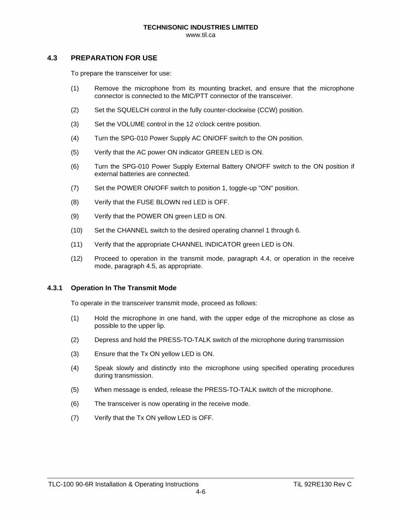
4.3 PREPARATION FOR USE
To prepare the transceiver for use: (1) Remove the microphone from its mounting bracket, and ensure that the microphone
connector is connected to the MIC/PTT connector of the transceiver.
(2) Set the SQUELCH control in the fully counter-clockwise (CCW) position.
(3) Set the VOLUME control in the 12 o'clock centre position.
(4) Turn the SPG-010 Power Supply AC ON/OFF switch to the ON position.
(5) Verify that the AC power ON indicator GREEN LED is ON.
(6) Turn the SPG-010 Power Supply External Battery ON/OFF switch to the ON position if external batteries are connected.
(7) Set the POWER ON/OFF switch to position 1, toggle-up "ON" position.
(8) Verify that the FUSE BLOWN red LED is OFF.
(9) Verify that the POWER ON green LED is ON.
(10) Set the CHANNEL switch to the desired operating channel 1 through 6.
(11) Verify that the appropriate CHANNEL INDICATOR green LED is ON.
(12) Proceed to operation in the transmit mode, paragraph 4.4, or operation in the receive mode, paragraph 4.5, as appropriate.
4.3.1 Operation In The Transmit Mode
To operate in the transceiver transmit mode, proceed as follows: (1) Hold the microphone in one hand, with the upper edge of the microphone as close as
possible to the upper lip.
(2) Depress and hold the PRESS-TO-TALK switch of the microphone during transmission
(3) Ensure that the Tx ON yellow LED is ON.
(4) Speak slowly and distinctly into the microphone using specified operating procedures during transmission.
(5) When message is ended, release the PRESS-TO-TALK switch of the microphone.
(6) The transceiver is now operating in the receive mode.
(7) Verify that the Tx ON yellow LED is OFF.
TECHNISONIC INDUSTRIES LIMITED www.til.ca
TLC-100 90-6R Installation & Operating Instructions TiL 92RE130 Rev C4-7
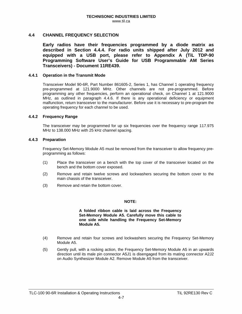
4.4 CHANNEL FREQUENCY SELECTION
Early radios have their frequencies programmed by a diode matrix as described in Section 4.4.4. For radio units shipped after July 2012 and equipped with a USB port, please refer to Appendix A (TiL TDP-90 Programming Software User’s Guide for USB Programmable AM Series Transceivers) - Document 11RE439.
4.4.1 Operation in the Transmit Mode
Transceiver Model 90-6R, Part Number 861605-2, Series 1, has Channel 1 operating frequency pre-programmed at 121.9000 MHz. Other channels are not pre-programmed. Before programming any other frequencies, perform an operational check, on Channel 1 at 121.9000 MHz, as outlined in paragraph 4.4.6. If there is any operational deficiency or equipment malfunction, return transceiver to the manufacturer. Before use it is necessary to pre-program the operating frequency for each channel to be used.
4.4.2 Frequency Range
The transceiver may be programmed for up six frequencies over the frequency range 117.975 MHz to 138.000 MHz with 25 kHz channel spacing.
4.4.3 Preparation
Frequency Set-Memory Module A5 must be removed from the transceiver to allow frequency pre-programming as follows: (1) Place the transceiver on a bench with the top cover of the transceiver located on the
bench and the bottom cover exposed.
(2) Remove and retain twelve screws and lockwashers securing the bottom cover to the main chassis of the transceiver.
(3) Remove and retain the bottom cover.
NOTE:
A folded ribbon cable is laid across the Frequency Set-Memory Module A5. Carefully move this cable to one side while handling the Frequency Set-Memory Module A5.
(4) Remove and retain four screws and lockwashers securing the Frequency Set-Memory
Module A5.
(5) Gently pull, with a rocking action, the Frequency Set-Memory Module A5 in an upwards direction until its male pin connector A5J1 is disengaged from its mating connector A2J2 on Audio Synthesizer Module A2. Remove Module A5 from the transceiver.
TECHNISONIC INDUSTRIES LIMITED www.til.ca
TLC-100 90-6R Installation & Operating Instructions TiL 92RE130 Rev C4-8
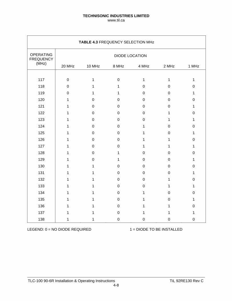
TABLE 4.3 FREQUENCY SELECTION MHz
DIODE LOCATION OPERATING FREQUENCY
(MHz) 20 MHz 10 MHz 8 MHz 4 MHz 2 MHz 1 MHz
117 0 1 0 1 1 1
118 0 1 1 0 0 0
119 0 1 1 0 0 1
120 1 0 0 0 0 0
121 1 0 0 0 0 1
122 1 0 0 0 1 0
123 1 0 0 0 1 1
124 1 0 0 1 0 0
125 1 0 0 1 0 1
126 1 0 0 1 1 0
127 1 0 0 1 1 1
128 1 0 1 0 0 0
129 1 0 1 0 0 1
130 1 1 0 0 0 0
131 1 1 0 0 0 1
132 1 1 0 0 1 0
133 1 1 0 0 1 1
134 1 1 0 1 0 0
135 1 1 0 1 0 1
136 1 1 0 1 1 0
137 1 1 0 1 1 1
138 1 1 0 0 0 0 LEGEND: 0 = NO DIODE REQUIRED 1 = DIODE TO BE INSTALLED
TECHNISONIC INDUSTRIES LIMITED www.til.ca
TLC-100 90-6R Installation & Operating Instructions TiL 92RE130 Rev C4-9
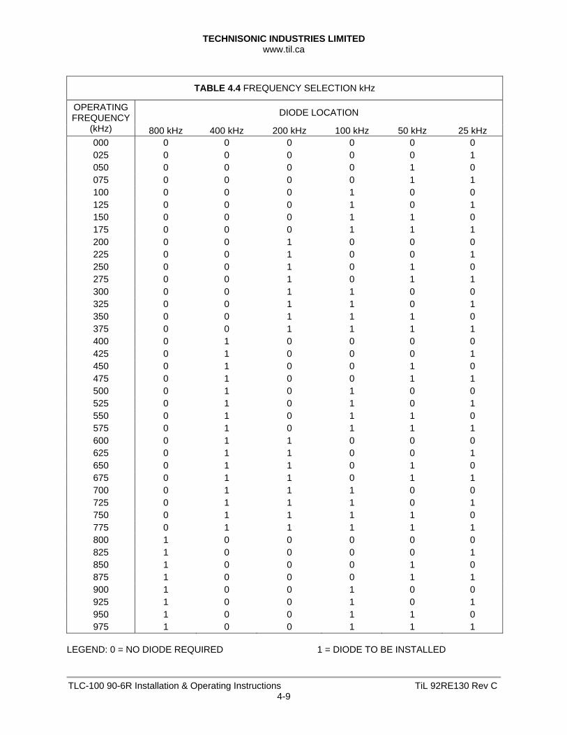
TABLE 4.4 FREQUENCY SELECTION kHz
DIODE LOCATION OPERATING FREQUENCY
(kHz) 800 kHz 400 kHz 200 kHz 100 kHz 50 kHz 25 kHz 000 0 0 0 0 0 0 025 0 0 0 0 0 1 050 0 0 0 0 1 0 075 0 0 0 0 1 1 100 0 0 0 1 0 0 125 0 0 0 1 0 1 150 0 0 0 1 1 0 175 0 0 0 1 1 1 200 0 0 1 0 0 0 225 0 0 1 0 0 1 250 0 0 1 0 1 0 275 0 0 1 0 1 1 300 0 0 1 1 0 0 325 0 0 1 1 0 1 350 0 0 1 1 1 0 375 0 0 1 1 1 1 400 0 1 0 0 0 0 425 0 1 0 0 0 1 450 0 1 0 0 1 0 475 0 1 0 0 1 1 500 0 1 0 1 0 0 525 0 1 0 1 0 1 550 0 1 0 1 1 0 575 0 1 0 1 1 1 600 0 1 1 0 0 0 625 0 1 1 0 0 1 650 0 1 1 0 1 0 675 0 1 1 0 1 1 700 0 1 1 1 0 0 725 0 1 1 1 0 1 750 0 1 1 1 1 0 775 0 1 1 1 1 1 800 1 0 0 0 0 0 825 1 0 0 0 0 1 850 1 0 0 0 1 0 875 1 0 0 0 1 1 900 1 0 0 1 0 0 925 1 0 0 1 0 1 950 1 0 0 1 1 0 975 1 0 0 1 1 1
LEGEND: 0 = NO DIODE REQUIRED 1 = DIODE TO BE INSTALLED
TECHNISONIC INDUSTRIES LIMITED www.til.ca
TLC-100 90-6R Installation & Operating Instructions TiL 92RE130 Rev C4-10
4.4.4 Pre-programming Channel Frequencies
Determine the number of channels to be used and the specific frequency of each channel for the particular transceiver being worked on. Prepare a list of channel numbers and frequencies to be pre-programmed, then proceed as follows: FREQUENCY SELECTION MHZ
Refer to Table 4.3 Frequency Selection MHz. Using the OPERATING FREQUENCY (MHz) column, find the desired frequency in MHz. Cross-refer to the DIODE LOCATION column, and record the locations in which diodes are to be installed, as indicated by a "1" entry. FREQUENCY SELECTION KHZ
Refer to Table 4.4, Frequency Selection kHz. Using the OPERATING FREQUENCY kHz column, find the portion of the desired frequency in kHz. Cross-refer to the DIODE LOCATION column, and record the locations in which diodes are to be installed, as indicated by a "1" entry.
NOTE:
Channel 1 is already pre-programmed for 121.900 MHz. It will be necessary to remove existing diodes if changing Channel 1 from 121.900 MHz.
INSTALLATION OF DIODES
Using the required number of diodes as determined during FREQUENCY SELECTION MHz and FREQUENCY SELECTION kHz, install each diode in its applicable location CR1 through CR72 for each channel to be used. Ensure that each diode is installed using correct polarity, as shown in Figure 4.2, using Multicore Solder SN63, 1 mm, or equivalent, and appropriate soldering iron. Trim leads on underside of printed wiring board and remove solder flux residue.

TECHNISONIC INDUSTRIES LIMITED www.til.ca
TLC-100 90-6R Installation & Operating Instructions TiL 92RE130 Rev C4-11
Figure 4.3 Frequency Set-Memory Module A5 - Component Layout
TECHNISONIC INDUSTRIES LIMITED www.til.ca
TLC-100 90-6R Installation & Operating Instructions TiL 92RE130 Rev C4-12
4.4.5 Installation of Module A5
After frequency selection has been completed, Frequency Set-Memory Module A5 shall be installed in the transceiver as follows: (1) Place Frequency Set-Memory Module A5 in position, engaging its male pin connector
A5J1 into its mating connector A2J2 on Audio Synthesizer Module A2. Gently push Module A5 downwards until it is correctly located.
(2) Secure Module A5 using four screws and lockwashers retained during disassembly. Tighten Screws. Reposition the folded ribbon cable across the module.
(3) Install the bottom cover on the main chassis of the transceiver utilizing screws and lockwashers retained during disassembly. Tighten screws.
(4) On the front panel label of the transceiver, mark the channel designation label with the appropriate frequency against each channel preprogrammed.
4.4.6 Operational Check
Connect the transceiver to a test bench, and perform an operational check of the transceiver in both transmit and receive modes of operation, checking each channel in use.

Technisonic Industries Limited
240 Traders Blvd., Mississauga, ON Canada L4Z 1W7 Tel: (905) 890-2113 Fax: (905) 890-5338
IMPORTANT WARRANTY
All communication equipment manufactured by Technisonic Industries Limited is warranted to be free of defects in Material or Workmanship under normal use for a period of one year from Date of Purchase by the end user. Warranty will only apply to equipment installed by a factory approved and/or authorized facility in accordance with Technisonic published installation instructions. Equipment falling under the following is not covered by warranty: • equipment that has been repaired or altered in any way as to affect performance, • equipment that has been subject to improper installation, • equipment that has been used for purposes other than intended, • equipment that has been involved in any accident, fire, flood, immersion or subject to
any other abuse. Expressly excluded from this warranty are changes or charges relating to the removal and re-installation of equipment from the aircraft. Technisonic will repair or replace (at Technisonic's discretion) any defective transceiver (or part thereof) found to be faulty during the Warranty Period. Faulty equipment must be returned to Technisonic (or its authorized Warranty Depot) with transportation charges prepaid. Repaired (or replacement) equipment will be returned to the customer with collect freight charges. If the failure of a transceiver occurs within the first 30 days of service, Technisonic will return the repaired or replacement equipment prepaid. Technisonic reserves the right to make changes in design, or additions to, or improvements in its products without obligation to install such additions and improvements in equipment previously manufactured. This Warranty is in lieu of any and all other warranties express or implied, including any warranty of merchantability or fitness, and of all other obligations or liabilities on the part of Technisonic. This Warranty shall not be transferable or assignable to any other persons, firms or corporations.
For warranty registration please complete the on-line Warranty Registration Form found at www.til.ca.

APPENDIX A This document contains designs and other information which are the property of Technisonic Industries Ltd. Except for rights expressly granted by contract to the Canadian Government, or to the United States Government, this document may not in whole or in part, be duplicated or disclosed or used for manufacture of the part disclosed herein, without the prior permission of Technisonic Industries Ltd.
TiL TDP-90 Programming Software
User’s Guide
for USB Programmable AM Series Transceivers
DOCUMENT No. 11RE439 REVISION A DATE OF ISSUE JULY 19, 2012
Technisonic Industries Limited
240 Traders Boulevard, Mississauga, Ontario L4Z 1W7 Tel: (905) 890-2113 Fax: (905) 890-5338
www.til.ca

This page left intentionally blank.
APPENDIX A 11RE439 Rev A
A-1
INTRODUCTION This document contains instructions for proper installation and operation of the TDP 90 software for USB programmable Technisonic AM series transceivers and details the various elements of the Graphical User Interface (GUI). NOTE: The images in this document are examples only and may not reflect your particular data settings, or current TDP software version. The TDP-90 programming software can be found under the “Programming Software” link at http://www.til.ca/ SOFTWARE INSTALLATION Note: The USB driver must be installed before attempting to use the TDP-90 software. USB Driver The USB hardware in your Technisonic AM transceiver is configured as a Virtual Com Port (“VCP”) which emulates a serial COM. This driver is available for free distribution from Future Technology Devices International (“FTDI”). Download and install the latest release of the VCP driver for Windows per the instructions on the web page located at this link: http://www.ftdichip.com/Drivers/VCP.htm TDP Software Download and install the latest release of the TDP-90 software for Windows from the web page located at this link: http://til.ca/content.php?page=programming-software-tdp90 Once completed there will be a “TDP90” icon on your computer desktop. TRANSCEIVER TO COMPUTER CONNECTION Connect the transceiver to the computer USB port using a standard USB-A male to USB-B male cable. The USB port is located on the rear panel of mobile and base station transceivers and on the front panel of rack mount transceivers.
APPENDIX A 11RE439 Rev A
A-2
GETTING STARTED
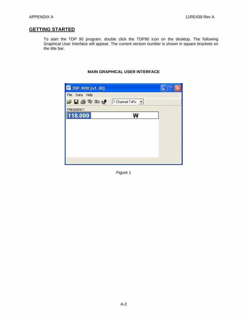
To start the TDP 90 program, double click the TDP90 icon on the desktop. The following Graphical User Interface will appear. The current version number is shown in square brackets on the title bar.
MAIN GRAPHICAL USER INTERFACE
Figure 1
APPENDIX A 11RE439 Rev A
A-3
ICONS AND PULL DOWN MENUS
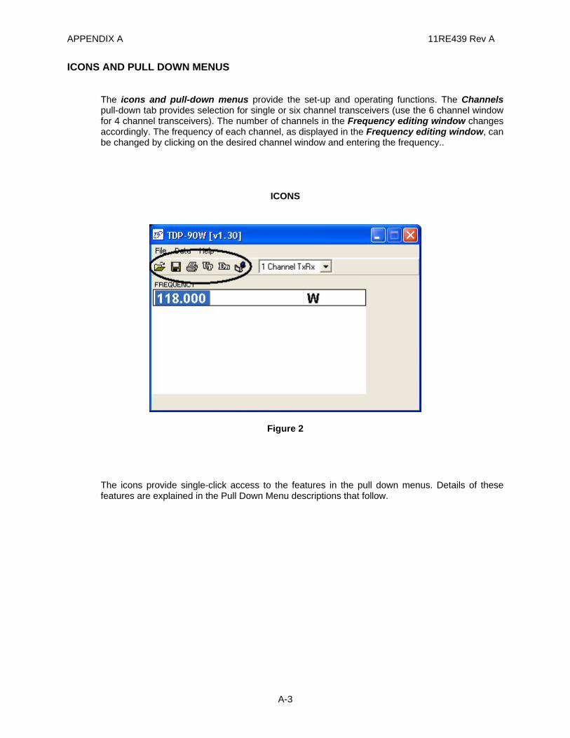
The icons and pull-down menus provide the set-up and operating functions. The Channels pull-down tab provides selection for single or six channel transceivers (use the 6 channel window for 4 channel transceivers). The number of channels in the Frequency editing window changes accordingly. The frequency of each channel, as displayed in the Frequency editing window, can be changed by clicking on the desired channel window and entering the frequency..
ICONS
Figure 2
The icons provide single-click access to the features in the pull down menus. Details of these features are explained in the Pull Down Menu descriptions that follow.
APPENDIX A 11RE439 Rev A
A-4
FILE MENU
Figure 3
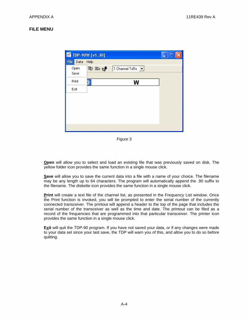
Open will allow you to select and load an existing file that was previously saved on disk. The yellow folder icon provides the same function in a single mouse click. Save will allow you to save the current data into a file with a name of your choice. The filename may be any length up to 64 characters. The program will automatically append the .90 suffix to the filename. The diskette icon provides the same function in a single mouse click. Print will create a text file of the channel list, as presented in the Frequency List window. Once the Print function is invoked, you will be prompted to enter the serial number of the currently connected transceiver. The printout will append a header to the top of the page that includes the serial number of the transceiver as well as the time and date. The printout can be filed as a record of the frequencies that are programmed into that particular transceiver. The printer icon provides the same function in a single mouse click. Exit will quit the TDP-90 program. If you have not saved your data, or if any changes were made to your data set since your last save, the TDP will warn you of this, and allow you to do so before quitting.
APPENDIX A 11RE439 Rev A
A-5
DATA MENU
Figure 4
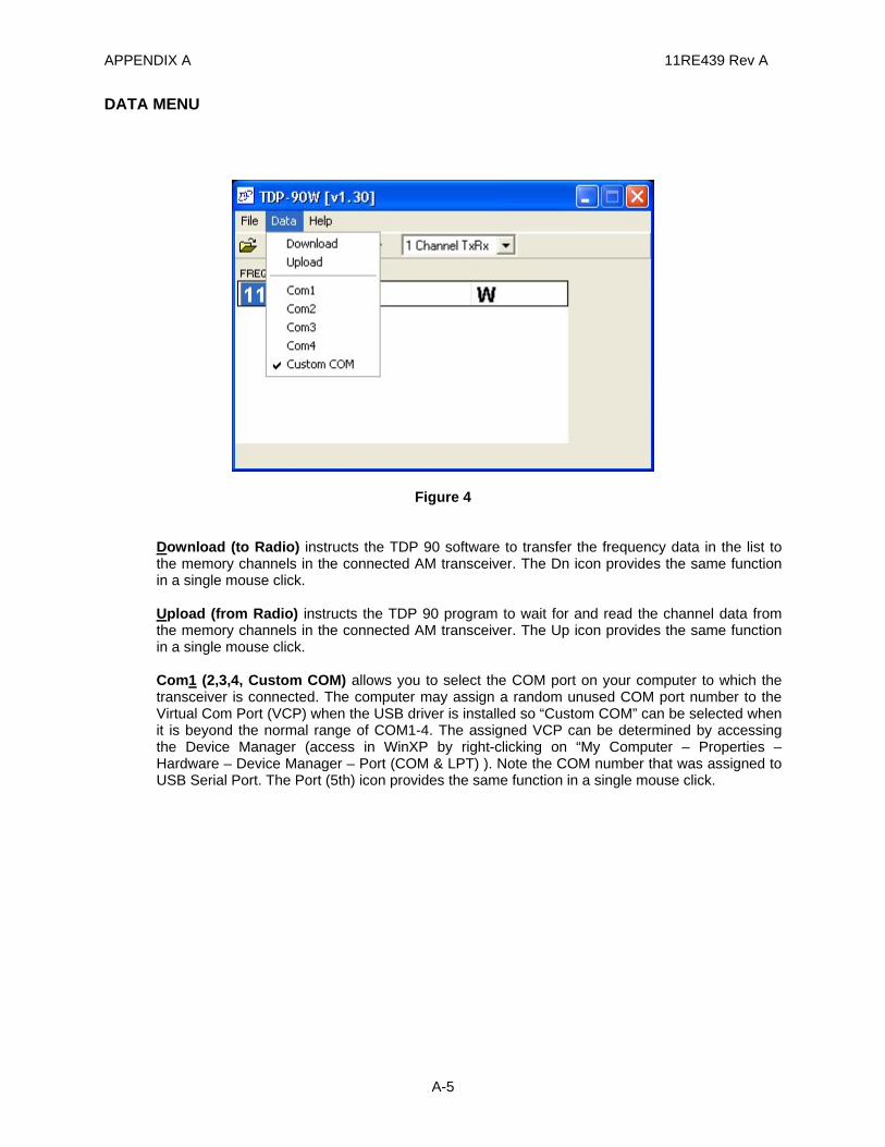
Download (to Radio) instructs the TDP 90 software to transfer the frequency data in the list to the memory channels in the connected AM transceiver. The Dn icon provides the same function in a single mouse click. Upload (from Radio) instructs the TDP 90 program to wait for and read the channel data from the memory channels in the connected AM transceiver. The Up icon provides the same function in a single mouse click. Com1 (2,3,4, Custom COM) allows you to select the COM port on your computer to which the transceiver is connected. The computer may assign a random unused COM port number to the Virtual Com Port (VCP) when the USB driver is installed so “Custom COM” can be selected when it is beyond the normal range of COM1-4. The assigned VCP can be determined by accessing the Device Manager (access in WinXP by right-clicking on “My Computer – Properties – Hardware – Device Manager – Port (COM & LPT) ). Note the COM number that was assigned to USB Serial Port. The Port (5th) icon provides the same function in a single mouse click.
APPENDIX A 11RE439 Rev A
A-6
HELP MENU
Figure 5
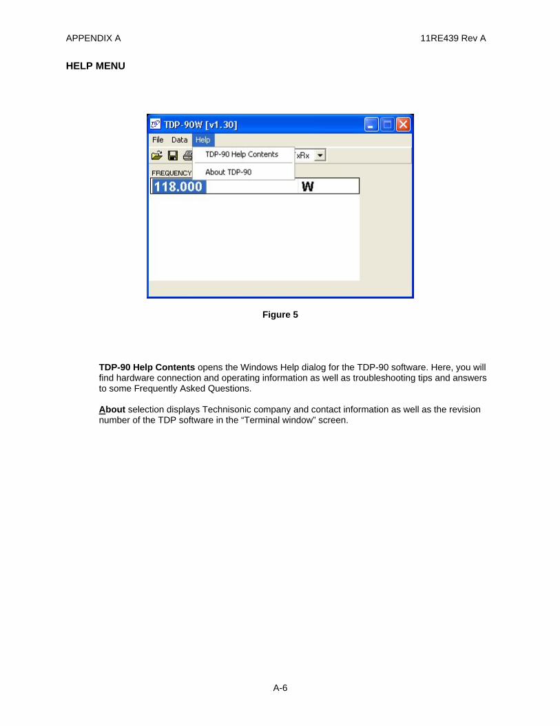
TDP-90 Help Contents opens the Windows Help dialog for the TDP-90 software. Here, you will find hardware connection and operating information as well as troubleshooting tips and answers to some Frequently Asked Questions. About selection displays Technisonic company and contact information as well as the revision number of the TDP software in the “Terminal window” screen.
APPENDIX A 11RE439 Rev A
A-7
CHANNEL SELECTION PULLDOWN
1 CHANNEL TRANSCEIVER
Figure 6
6 CHANNEL TRANSCEIVER
Figure 7
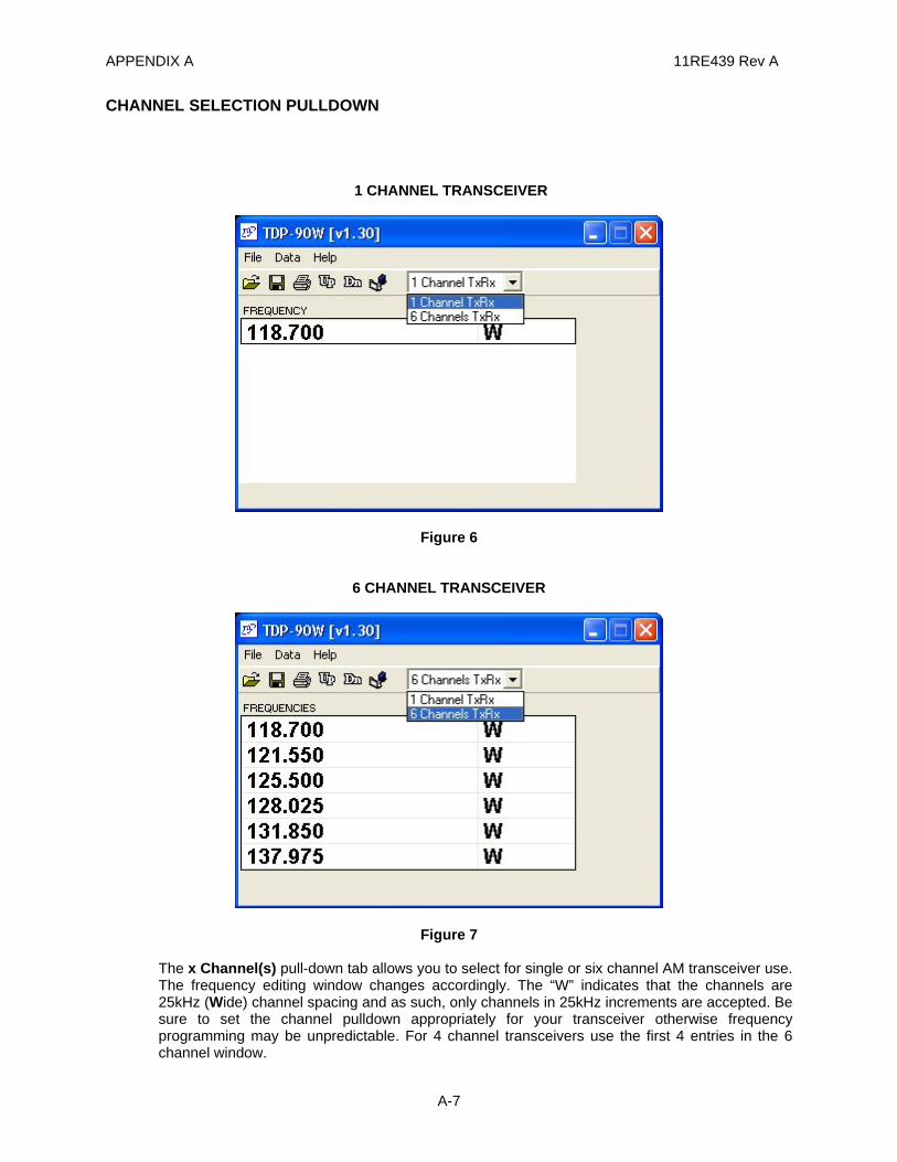
The x Channel(s) pull-down tab allows you to select for single or six channel AM transceiver use. The frequency editing window changes accordingly. The “W” indicates that the channels are 25kHz (Wide) channel spacing and as such, only channels in 25kHz increments are accepted. Be sure to set the channel pulldown appropriately for your transceiver otherwise frequency programming may be unpredictable. For 4 channel transceivers use the first 4 entries in the 6 channel window.
APPENDIX A 11RE439 Rev A
A-8
SAMPLE UPLOAD AND DOWNLOAD
(1) Connect the transceiver to the computer USB port using a standard USB-A male to USB-B male cable. The USB port is located on the rear panel of mobile and base station transceivers and on the front panel of rack mount transceivers. Turn on the power to the transceiver.
(2) Assuming that the USB driver is already installed, determine which Virtual Com Port has been assigned by accessing the Device Manager (accessed in WinXP by right-clicking on “My Computer – Properties – Hardware – Device Manager – Ports (COM & LPT) ). Note the COM number that was assigned to USB Serial Port.
(3) Run the TDP-90 program on the computer.
(4) Click on the Data pull-down list and select the serial port to which the transceiver is connected. Select Custom COM and enter the assigned port number if it is outside the normal range of Com1-4.
(5) Set the program for 1 or 6 channels as applicable using the channel pulldown list.
(6) Click on the Up icon to retrieve the frequencies from the radio. “UPLOADING” will appear at the bottom of the window as data is being transferred.
(7) Edit the frequencies as desired. (The program only accepts 25 kHz spaced frequencies.)
(8) Click on the Dn icon to copy the frequencies to the transceiver. “DOWNLOADING” will appear at the bottom of the window as data is being transferred.
(9) Click on the diskette icon to save the file. Hint: Use the transceiver serial number or some other unique filename to identify the specific transceiver. The program will automatically append the .90 suffix to the filename.
(10) Click on the printer icon to print a hard-copy of the frequencies.