Embed Size (px)
Citation preview

Installation andOperating Instructions
Hinge band conveyor type S
GB


3
Hinge band conveyor type S
Table of contents
Page
1 Description of machine and functions .............................................................................. 5
2 Danger and safety instructions .......................................................................................... 6
2.1 General instructions ....................................................................................................... 6
2.2 Instructions for repair and maintenance work and malfunctions ................................... 7
3 Unpacking and handling ..................................................................................................... 8
3.1 Unpacking ...................................................................................................................... 8
3.2 Handling ......................................................................................................................... 8
4 Assembly and installation ................................................................................................ 9
4.1 Screwing together several container parts .................................................................... 9
4.2 Electrical connection ...................................................................................................... 9
4.3 Loosening the tension device hinge band .................................................................... 10
4.4 Mounting the hinge band ............................................................................................. 12
4.5 Mounting the shackle type connectors ........................................................................ 13
4.6 Mounting the locking bolts ........................................................................................... 14
4.7 Tensioning the hinge band ........................................................................................... 16
5 Switching on and operating ............................................................................................. 18
5.1 Before initial operation ................................................................................................. 18
5.2 Switching on................................................................................................................. 18
5.3 Switching off ................................................................................................................ 18
6 Maintenance ....................................................................................................................... 19
6.1 Adjusting the drive shaft .............................................................................................. 19
6.2 Changing the broach bars ........................................................................................... 19
6.3 Checking the hinge bande tension ............................................................................... 20
6.4 Changing individual hinge band plates ......................................................................... 20
6.4 Maintenance table ....................................................................................................... 18
7 Information on coolants / tanks ....................................................................................... 21
8 Maintenance table ............................................................................................................. 22
9 Eliminating malfunctions ................................................................................................. 25
10 Accessories ....................................................................................................................... 26
10.1 Stripping device ........................................................................................................... 26


5
Hinge band conveyor type S
1 Description of machine and functions
Function- Conveying metal shavings and small parts
- Prepurifying the cooling lubricant (for wet processing)
Scope- Decentral use in single and interlinked machine tools
- Central use for waste disposal from machine groups and entire production areas
- Suitable for long swarfs, snarl chips, wool-type filings, dry and wet processing
Mode of operation- Loose material falls in feed opening onto the endless hinge band
- Continuous transfer of the loose material to the discharge opening
- Throwing the loose material at the discharge opening into the container or anotherconveyer for removal.
- Do not use the plant for other than the intended purposes.- Note the Regulation for the Prevention of Accidents (Unfallverhütungs-
vorschrift) VBG 10 when operating the plant.- The discharge station must be visible during machine controlled operation.
Noise level: < 70 dB(A)
Optional equipment- Coolant tank- Coolant purification systems (e.g. magnetic separator, centrifugal separator,
band filter, superfine strainer)- Low lift and jetting pumps for purification elements and machines- Swarf mill- Brush-off device- Sustainer- Chip carriage- Sieve drum- Piping with aggregates, valves, etc.
Since nearly every plant is constructed for the special needs of the customer, deviations from the form and position of the parts and structuralcomponents described in this documentation may occur. In this case the operating instructions should be applied analogously.

6
Hinge band conveyor type S
2 Danger and safety instructions
2.1 General instructions
- Always observe all statements and instructions in theoperating instructions delivered with the plant.
- It is forbidden for unqualified persons to work at the plant.- Observe correct fastening if components were installed by
customer.- Never bypass safety contrivances (e.g. safety clutch).- The operation of safety contrivances must always be
guaranteed.
- Work on the electrical plant may only be carried out byqualified personnel.
- Observe the relevant VDE requirements and connectionrequirements of the responsible Electricity Board.
- Do not stand in or reach into the feed opening.
- Do not reach into the discharge opening.
- Cover the scraper belt and all driving elements beforestarting.
- Do not remove covers while plant is in operation.

7
Hinge band conveyor type S
2.2 Instructions for repair and maintenance work and for malfunctions
- Switch off the main switch.- Secure the plant against being started accidentally.
- Ensure that the plant is dead.
- Depressurize the plant.
- Close pipe valves.- Remove all noxious materials.- Coolants must not enter the environment.
- When handling chips, wear protective clothing, safety bootsand protective gloves.
0I

8
Hinge band conveyor type S
3 Unpacking and handling
3.1 Unpacking
Scraper conveyors over 8 m in length are delivered in several container parts.
The hinge bands of divided conveyors are rolled up on separate pallets.
For conveyors in several parts, scraper belts are rolled up on separate pallets.
Small parts (screws, sealings etc.) are delivered loose in the scraper conveyorcontainer or in separate packing.
If mounting rails are required for inserting the hinge band, they are fastened to thehinge band or pre-mounted on the hinge band conveyor and lacquered in red.
Mounting rails must absolutely be preserved because the hinge band cannot beinserted without them.
3.2 Handling
- Do not stop beneath suspended loads!
- By crane:Always transport by crane if no longer in theoriginal packing. Use the suspension devicesprovided (e.g. eye hooks, lifting screws)
- By stacker truck:Only in the original packing andwith the greatest of care.

9
Hinge band conveyor type S
2
2
(1) 1
2
3
4
4 Assembly and installation
- Put plant on even ground!- Ensure a firm and secure position.- Secure the plant against being started accidentally.
4.1 Screwing together several container parts
- Join container parts at the joint locations and align in parallel.
Note identification markings (2) of the container flanges.
The identification marking (numbers or symbols) must agree with that of the oppositeflange (3).
- Insert the sealings supplied (1) and join container parts completely.
- Align the containers such that all bore holes are in alignment with the container flangesopposite.
- Insert but do not tighten hexagon head screws and hexagon nuts.
- Drive in preassembled rollpin spring (4).
- Tighten hexagon head screws
4.2 Electrical connection
- Connect power supply to motor(s) and pump(s)
- Note the correct direction of rotation (see arrow)

10
Hinge band conveyor type S
type 1
Model with flange bearing:
- Remove the top coverings (2)
- Loosen the fastening screws (4) on bothsides of the gearing end frame but do notunscrew completely
- Loosen clamping bolts (3) on both sides ofthe gearing end frame and turn backwardcompletely
- Loosen hexagon head cap screw (5) onboth sides and remove hand guard (6)
- Push backward gearing end frame (1)against the conveying direction to the stop
- Tighten fastening screws (4) on both sidesof the gearing end frame
- Mount hinge band mounting rails(see Chapter 4.4)
type 2
Model with pedestal bearing:
- Dismantle protective covering at the drive
- Loosen the fastening screws (1) on the drivemotor (2)
- Turn back clamping bolts (3) on both sides
- Release the tension of the drive chain bymoving the drive motor in the direction ofthe arrow (2)
- Loosen the fastening screws (4) on thepedestal bearing
- On both sides, evenly screw in the clampingscrews (6) and tighten the hinge band in thedirection of the arrow
- Tighten the fastening screws (4) at thepedestal bearing
- Mount hinge band mounting rails(see Chapter 4.4)
4.3 Loosening tension device hinge band
1
1
3
2
6
4
5
Type 2
Type 1
2
34
5
6
1

11
Hinge band conveyor type S
Type 3
Model with band support:
- Disassemble hand guard (1) on the left and onthe right by removing the fastening screw (6)
- Loosen the fastening screws (2) on both sidesof the drive motor (3) but do not unscrewcompletely
- Loosen lock nuts (4) of the clamping bolts (5)
- Turn back the clamping bolts (5) completely
- Push backward the drive motor against theconveying direction (direction of arrow) to thestop
- Tighten fastening screws (2) on both sides ofthe drive motor
- Mount mounting rails (see chapter 4.4)
Type 4
Deflection side model:
- Loosen lock nuts (2) of the clamping bolts (3) on both sides
- Open the clamping bolts (3) at the guide rolleras far as possible
- Press the guide roller (1) towards thedischarge opening (direction of arrow)
- Fix clamping bolts (3) with lock nuts (2)in loosened position on both sides
- Mount mounting rails (see chapter 4.4)
Type 3
Type 4
1
2
3
12 3
45
2
6
2
12
Hinge band conveyor type S
1
2
34
5
6
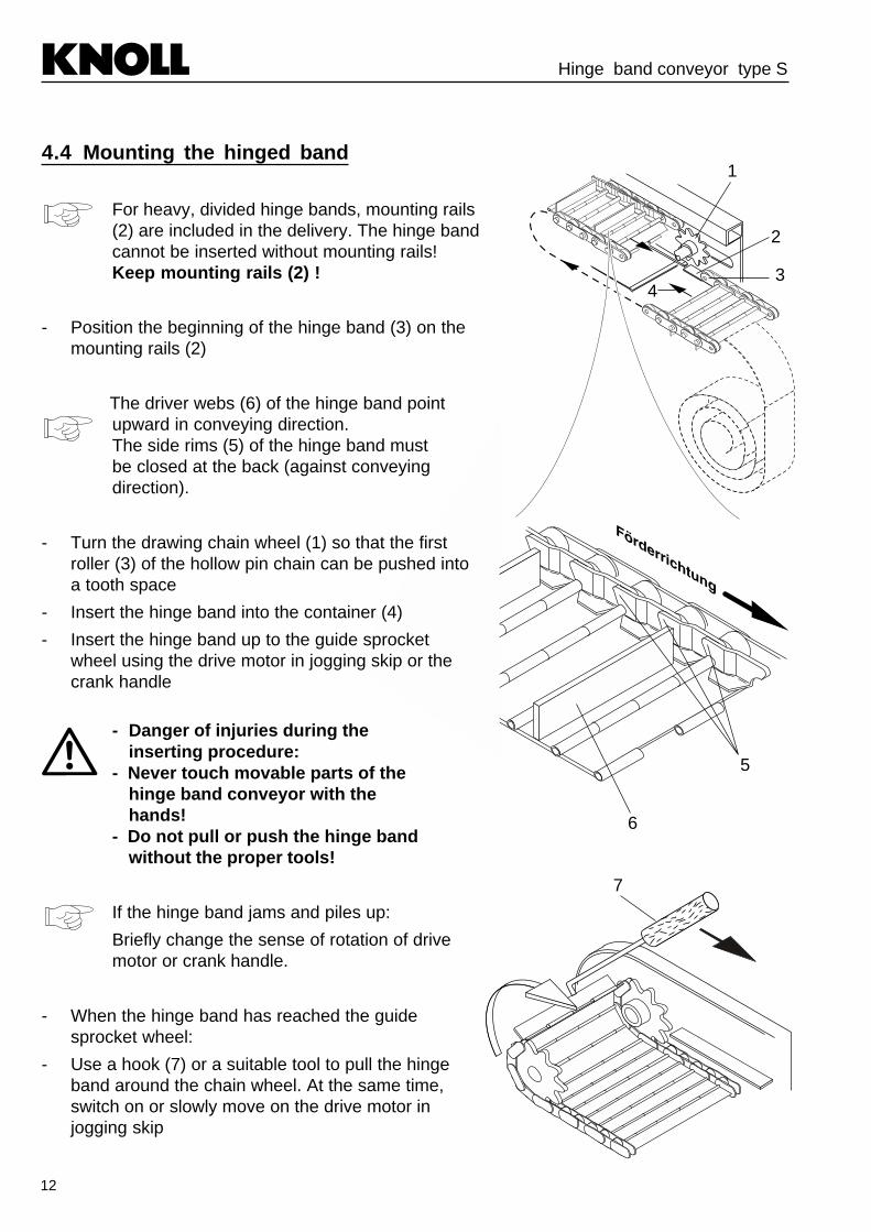
4.4 Mounting the hinged band
For heavy, divided hinge bands, mounting rails(2) are included in the delivery. The hinge bandcannot be inserted without mounting rails!Keep mounting rails (2) !
- Position the beginning of the hinge band (3) on themounting rails (2)
The driver webs (6) of the hinge band pointupward in conveying direction.The side rims (5) of the hinge band mustbe closed at the back (against conveyingdirection).
- Turn the drawing chain wheel (1) so that the firstroller (3) of the hollow pin chain can be pushed intoa tooth space
- Insert the hinge band into the container (4)
- Insert the hinge band up to the guide sprocketwheel using the drive motor in jogging skip or thecrank handle
- Danger of injuries during theinserting procedure:
- Never touch movable parts of thehinge band conveyor with thehands!
- Do not pull or push the hinge bandwithout the proper tools!
If the hinge band jams and piles up:
Briefly change the sense of rotation of drivemotor or crank handle.
- When the hinge band has reached the guidesprocket wheel:
- Use a hook (7) or a suitable tool to pull the hingeband around the chain wheel. At the same time,switch on or slowly move on the drive motor injogging skip
7

13
Hinge band conveyor type S
1 2 3 4 5
8
910
11
12
- Danger of injuries!- Never pull the hinge band around
the guide sprocket wheel by hand
- Continue the inserting procedure until thebeginning of the hinge band has reached thedrawing chain wheels.
- Steadily pull the hinge band with a hook or asuitable tool in conveying direction to avoidpiling up or jamming.
- Switch off the drive motor
- Only Type S2:
Insert a roller (8) between the cover plates(9) of the hollow pin chains and fasten withlocking bolts (11). Blocking of the hingeband (12) is thus rendered more difficult
Depending on the hinge band size, two ormore people are needed for inserting. Thedrive motor or a crank handle can be usedfor inserting. See chapter 6.2 for mountingthe crank handle
4.5 Mounting the shackle type connectors- Insert the roller (3) between the cover
plates (2) of the hollow pin chain (onlyrequired for Type S2)
- Connect the ends of the hollow pin chainswith shackle type connectors (1)
The bolts of the shackle typeconnectors (1) point outward.
- Place the cover plates (4) onto theinserted shackle type connectors
- Mount the locking rings (5)
- Remove the mounting rails

14
Hinge band conveyor type S
4.6 Mounting the locking bolts
Type 1
Model with flange bearing:
- Turn the hinge band such that theconnecting brackets of the hinge bandplates are flush with the mountingboring (4)
- Mount a washer (2) with split-pin (1) onthe locking bolt (3)
- Join the hinge band plates.
- Put the locking bolts (3) through theshackle type connectors (7) and theconnecting brackets (6) of the jointhinge band plates
- Mount the second washer (2) and split-pin(1) on the locking bolt
Type 2
Model with pedestal bearing:
- Turn the hinge band such that theconnecting brackets (6) of the hinge band plates are accessible throughthe oblong hole (5)
- Mount a washer (2) with split-pin (1) onthe locking bolt (3)
- Join the hinge band plates
- Put the locking bolts (3) through theshackle type connectors (7) and theconnecting brackets (6) of the jointhinge band plates
- Mount the second washer (2) and split-pin(1) on the locking bolt
Dismantling is carried out in reverseorder
Type 2
2
13 2
1
5
6
73
Type 1
2
13
2
1
4

15
Hinge band conveyor type S
Type 3
with band support:
- Turn the hinge band such that theconnecting brackets of the hinge bandplate are in flush with the mountingboring (8)
- Mount a washer (2) with split-pin (1)on the locking bolt (3)
- Join the hinge band plates
- Put the locking bolts (3) through theshackle type connectors (7) and theconnecting brackets (6) of thejoint hinge band plates
- Mount the second washer (2) andsplit-pin (1) on the locking bolts
Type 4
Deflection side model:
- Turn the hinge band such that theconnecting brackets (6) of the hingeband plates are accessible through theoblong hole (8)
- Mount a washer (2) with split-pin (1)on the locking bolt (3)
- Join the hinge band plates
- Put the locking bolts (3) through theshackles type connectors (7) and theconnecting brackets (6) of the jointhinged band plates
- Mount the second washer (2) andsplit-pin (1) on the locking bolt
Dismantling is carried out inreverse order.
1 1
23
2
8
8
23
2
1
1
Type 4
Type 3
6
73

16
Hinge band conveyor type S
4.7 Tensioning the hinge band
Type 1
Model with flange bearing:
- Loosen the fastening screws (3) on bothsides of the gearing end frame
- Loosen the lock nuts (1) of the clampingbolts (2) on both sides
- On both sides, evenly screw in the clampingbolts in the direction of the arrow
- Check hinge band tension as described inchapter 6.3
- Tighten the lock nuts of the clamping screws
- Tighten the fastening screws (3) at the gearend frame
Type 2
Model with pedestal bearing:
- Loosen the fastening screws (1) at thedrive motor (2)
- Turn back the clamping bolts (3) on bothsides
- Loosen the fastening screws (4) on thepedestal bearing on both sides
- On both sides, evenly screw in the clampingbolts (5) and tension the hinge band in thedirection of the arrow
- Check hinge band tension (see chapter 6.3)
- Tighten the fastening screws (4) at thepedestal bearing
- Tension the drive chain by means of theclamping bolts (3) by moving the drivemotor (2) in the direction of the arrow
- Check the chain tension of the drivechain (see chapter 8)
Type 1
3
2
1
Type 2
1
1
3
2
5
4

17
Hinge band conveyor type S
Type 3
with band support:
- Loosen the fastening screws (1) on bothsides of the gearing end frame (4), butdo not unscrew completely
- Loosen the lock nut (2) of the clampingbolt (3) on both sides
- On both sides, evenly tighten theclamping bolts while checking the hingeband tension continuously as describedin chapter 6.3
- Tighten lock nuts (3)
- Tighten fastening screws (1) on bothsidesof the gearing end frame (4)
Type 4
Deflection model:
- Loosen lock nuts (2) on both sides
- On both sides, evenly tighten the clampingbolts (3) in the direction of the arrow
- Check hinge band tension continuously asdescribed in chapter 6.3
- Check the adjustment of the guide roller (1)(see chapter 6.3)
- Tighten lock nuts (2)
1
1
23
4
1
1
2
3
Type 3
Type 4

18
Hinge band conveyor type S
5 Switching on and operating
5.1 Before initial operation
- Electrical components must be connected by qualified personnel (note voltage, frequency,strength of current and direction of rotation)
- Do a leak test on pipings for liquids (possible transport damage)
- Set all switches at “0” or “OFF”
- Fill up with required liquids (coolants, lubricants, oils, etc.)
- The entire installation must be free of coarse parts (tools, etc.)
5.2 Switching on
- Make sure that nobody is in the danger area of the hinge band conveyor!- For the operation of the installation, the regulations for prevention of
accidents VBG 10 must be observed!- All danger areas accessible to people must be covered!
Sequence for switching on:
- Lifting pump(s)*- Low lift pump(s)*- Scraper conveyor- Auxiliary aggregates (swarf mill, sieve drum, magnetic drum etc.)*- Jetting pump(s)*
5.3 Switching off
Switch off scraper conveyors with coolant system with a time delay of approx. 5 mins. tothe processing machine (purification of the coolant)
Sequence for switching off:
- Jetting pump(s)*- Low lift pump(s)*- Lifting pump(s)*- Auxiliary aggregates (swarf mill, sieve drum, magnetic drum etc.)*- Scraper conveyor
*if supplied with this model

19
Hinge band conveyor type S
300mm
12mm
A
B
A B
M8
M10
2625
3635
Ø
A A
6 Maintenance
6.1 Adjusting the drive shaft
Only necessary if distance “A” is not thesame on both sides
- Loosen the axial shaft locks on both sides ofthe drive shaft bearings
- Move the chain wheels with the shaft in anaxial direction until distance “A” is the same onboth sides
- Fasten the axial shaft locks on both sides
6.2 Attaching the manual crank
Examples for the use of the crankhandle:
Aligning the hinge band for dismantling
Loosening coarse parts blocking thehinge band
Reversing mode when not possible withdrive motor
- Loosen connection between drive motor andsafety clutch. If necessary remove drive mo-tor.
- Expel the rollpin spring of the safety clutch
- Remove the safety clutch from the drive shaft
- Attach the manual crank to the drive shaft andinsert hexagon head screw. If necessarymake manual crank as illustrated.

20
Hinge band conveyor type S
6.3 Checking the hinge band tension
- Switch off the hinge band conveyor and secureagainst unintended start-up
- Check the hinge band tension between the driveshaft and container bottom
Hinge band tension:
When applying moderate pressure frombelow, the hinge band must give approx.10 mm
Dimension A must be the same on bothsides
~ 1
0 m
m
A
6.4 Changing individual hinge band plates
- Dismantle the hinge band
- Cut off the heads (3) of the connecting bolts (1) using appropriate tools (e.g. by means of aabrasive cutting-off machine, saw, etc.) on one side
- Pull the connecting bolts (1) out of the hinge band plate
- Remove hinge band plate (2)
To install a new hinge band, clamping bolts (1) (with borings), washers and split-pins have to be used.
Mind the length of the connecting bolts such as they do not rub at the container.
2Hinge band plate
3
1
2Hinge band plate
with scraper
2Hinge band plate
with driver rail
1

21
Hinge band conveyor type S
7 Information on coolants / tanks
- Circulate coolants continuously (weekend circulation recommended)
- Do not feed any organic matter
- Avoid foreign oil charge
- Temperature should be below 25°C for emulsion, if possible
- pH-value should be within neutral range
- Hardness of the initial water should not exceed 15° dH
- Hardness due to upgrading must not exceed 20° dH
Cleaning the coolant tanks
- Cleaning intervals greatly depend upon the kind of processing, material, coolant andworking hours; no general interval can therefore be specified
A cleaning interval between four and eight weeks is recommended as standard value

22
Hinge band conveyor type S
Dri
ve-
Driv
e ch
ain
(onl
y fo
r m
odel
with
flan
ge b
earin
g w
ithch
ain
driv
e)
- D
rive
chai
n (o
nly
for
mod
elw
ith p
edes
tal b
earin
g w
ithch
ain
driv
e)
Che
ck te
nsio
n an
d tig
hten
if n
eces
sary
,lu
bric
ate
driv
e ch
ain
Che
ck te
nsio
n an
d tig
hten
if n
eces
sary
,lu
bric
ate
driv
e ch
ain
Ste
ps:
-R
emov
e pr
otec
tive
cove
ring
(1)
-Lo
osen
hex
agon
hea
d ca
psc
rew
(2)
-P
ress
take
-up
pulle
y (4
) in
the
dire
ctio
n of
the
arro
w (
5)ag
ains
t driv
e ch
ain
(3)
(for
ceof
pre
ssur
e ap
prox
. 20
N)
-T
ight
en h
exag
on h
ead
cap
scre
w (
2)-
Mou
nt p
rote
ctiv
e co
verin
g(1
)
-R
emov
e pr
otec
tive
cove
ring
Loos
en h
exag
on h
ead
cap
scre
ws
(7)
-E
venl
y un
scre
w h
exag
onhe
ad c
ap s
crew
s (8
) in
the
dire
ctio
n of
the
arro
w (
6)un
til th
e te
nsio
n of
the
driv
ech
ain
is a
ppro
x. 2
0 N
-T
ight
en h
exag
on h
ead
cap
scre
ws
(7)
-M
ount
pro
tect
ive
cove
ring
21 34
5
8
7
6
3 m
onth
s
3 m
onth
s
Su
bas
sem
bly
/In
terv
alA
ctio
nS
afet
y in
stru
ctio
ns/
com
po
nen
tre
mar
ks
8 Maintenance table

23
Hinge band conveyor type S
Check wear and smooth running
Check tension and tighten if necessary
Check for damage
See operating instructions of manufacturer
Check for ruptures and damage
Check function
Check function
Empty and clean
See operating instructions of manufacturer
Check for leaks, damage and corrosion
Check stability
Check guide rails for wear
Check and replace if necessarywhen changing the hinge band
For setting, see Chapter 4.5
Replace damaged parts
Replace defective wiring
Exceed both switch points bymanual actuation
Hazardous substances must inno case penetrate
Container must be safely andsolidly fastened
Check when changing the hingeband
- Bearing of drive shaft andlateral axis, chain wheels
Hinge band
Electrical equipment
- Motor(s)
- Wiring
- Level switch
- Protective gear
Sieve basket
Pumps
Containers
---
3 months
3 months
---
3 months
3 months
3 months
---
---
6 months
6 months
---
Subassembly/ Interval Action Safety instructions/component remarks

24
Hinge band conveyor type S
Check for contamination (sludge deposits) andclean, if need be.
Depending on the tooling method,the interval may be greatlyshortened.
Coolant tanks are special accesso-ries and are therefore not installed inevery plant.
500workinghours
Coolant tanks
Subassembly/ Interval Action Safety instructions/component remarks

25
Hinge band conveyor type S
Rep
lace
driv
e ch
ain
Driv
e in
new
rol
lpin
spr
ing
Rem
ove
part
sT
urn
the
driv
e ba
nd in
rev
erse
dire
ctio
n if
nece
ssar
y (s
ee C
hap-
ter
6.2)
Afte
r re
star
ting,
the
safe
ty c
lutc
hau
tom
atic
ally
ree
ngag
es a
ndco
ntin
ues
to o
pera
te
Imm
edia
tely
sw
itch
off s
war
f con
-ve
yor
Info
rm s
ervi
ce te
chni
cian
or
re-
plac
e co
mpl
ete
safe
ty c
lutc
hN
ever
brid
ge th
e sa
fety
clu
tch
orm
odify
the
setti
ng
Dis
mou
nt h
inge
ban
d an
d lo
okov
er in
stal
latio
n
Adj
ust d
rive
shaf
t (se
e C
hapt
er6.
1)
Driv
e ch
ain
torn
(fo
r m
odel
with
cha
in d
rive)
Rol
lpin
spr
ing
of th
e sa
fety
clu
tch
on th
edr
ive
shea
red
off
Hin
ge b
and
bloc
ked
by la
rge
part
s, s
afet
ycl
utch
has
trig
gere
d
Saf
ety
clut
ch d
efec
tive
(loud
rat
tling
noi
se)
Acc
umul
atio
n of
sw
arfs
in fr
ont o
f the
gui
desp
rock
et w
heel
Axi
al s
haft
lock
loos
e
Mal
fun
ctio
nP
oss
ible
cau
ses
Rem
edy
9 Eliminating malfunctionsD
rive
mot
or r
aces
, hin
ge b
and
does
not
mov
e
Hin
ge b
and
does
not
mov
e ce
ntra
lly(s
trik
es th
e ha
nd g
uard
on
one
side
)

26
Hinge band conveyor type S
10 Accessories
10.1 Stripping device
Scope
- Used in case snarl chips are forming as well as in case chips are conglutinating(e.g. due to oil)
Function
- By means of spring pressure (4) a movable scraper (1) will be moved along thehinge band (2)
- Conglutinated chips will be eliminated
Setting
- The stripping device (1) has to fit close to the hinge band (2) (A)
- Move stripping device fully in the direction of the arrow (B) until it reaches the stop
- Set the adjusting screw (3) to a distance (C) of 2 mm approx between the screw (3)and the scraper (1).
A
B C
2
3
4
1


2217
4/S
-bed
-gbV
1.1.
pm6/
09.9
9Wü
Kühlmittelreinigungsanlagen KNOLL Maschinenbau GmbH Telefon 07581/2008-0Späneförderanlagen Schwarzachstr. 20, Postf. 1362 Telefax 07581/2008-140Nieder- und Hochdruckpumpen D-88342 Bad Saulgau E-mail [email protected]
web www.knoll-mb.de