Embed Size (px)
Citation preview

6720
8861
22 (2
018/
07)
Installation and operating instructions
Control unit and key
Comfort+ II RFselect
advance
select
advance
menu

Table of contents
Table of contents
1 Explanation of symbols and safety instructions . . . . . 31.1 Explanation of symbols . . . . . . . . . . . . . . . . . . . . . . 31.2 General safety instructions . . . . . . . . . . . . . . . . . . . 3
2 Product information . . . . . . . . . . . . . . . . . . . . . . . . . . . . 42.1 User interface. . . . . . . . . . . . . . . . . . . . . . . . . . . . . . 42.2 Key . . . . . . . . . . . . . . . . . . . . . . . . . . . . . . . . . . . . . . 5
3 Installation and commissioning. . . . . . . . . . . . . . . . . . . 63.1 Installation and commissioning key . . . . . . . . . . . . 63.2 Installation and commissioning of the control
unit . . . . . . . . . . . . . . . . . . . . . . . . . . . . . . . . . . . . . . 63.3 Putting the control unit into operation . . . . . . . . . . 8
4 Using the control unit . . . . . . . . . . . . . . . . . . . . . . . . . . . 84.1 Standard display . . . . . . . . . . . . . . . . . . . . . . . . . . . 84.2 Call up/select temperature setting of
operating modes . . . . . . . . . . . . . . . . . . . . . . . . . . . 94.2.1 Room temperature display of Auto operating
mode. . . . . . . . . . . . . . . . . . . . . . . . . . . . . . . . . . . . . 94.2.2 Room temperature display of On operating
mode. . . . . . . . . . . . . . . . . . . . . . . . . . . . . . . . . . . . . 94.2.3 Room temperature display of Off operating
mode. . . . . . . . . . . . . . . . . . . . . . . . . . . . . . . . . . . . . 94.2.4 Setting the room temperature . . . . . . . . . . . . . . . 104.3 Key lock. . . . . . . . . . . . . . . . . . . . . . . . . . . . . . . . . . 10
5 Settings in the main menu . . . . . . . . . . . . . . . . . . . . . . 105.1 Time program for adjusting the heating . . . . . . . . 115.2 Setting the DHW time program . . . . . . . . . . . . . . . 115.3 Deactivate switching times . . . . . . . . . . . . . . . . . . 125.4 Holiday . . . . . . . . . . . . . . . . . . . . . . . . . . . . . . . . . . 125.5 Information. . . . . . . . . . . . . . . . . . . . . . . . . . . . . . . 125.6 Settings. . . . . . . . . . . . . . . . . . . . . . . . . . . . . . . . . . 13
6 Settings in the service menu (installer) . . . . . . . . . . . 14
7 Key . . . . . . . . . . . . . . . . . . . . . . . . . . . . . . . . . . . . . . . . . . 167.1 Connecting/disconnecting the control unit . . . . . 16
8 Troubleshooting . . . . . . . . . . . . . . . . . . . . . . . . . . . . . . . 178.1 Rectify fault . . . . . . . . . . . . . . . . . . . . . . . . . . . . . . 178.1.1 Faults in the control unit or key . . . . . . . . . . . . . . . 17
9 Maintenance . . . . . . . . . . . . . . . . . . . . . . . . . . . . . . . . . . 189.1 Replace batteries of control unit . . . . . . . . . . . . . . 18
10 Product data for energy consumption . . . . . . . . . . . . 19
11 Simplified EU Declaration of Conformity regarding radio equipment . . . . . . . . . . . . . . . . . . . . . 19
12 Specifications. . . . . . . . . . . . . . . . . . . . . . . . . . . . . . . . . 19
13 Environmental protection/disposal . . . . . . . . . . . . . . 20
14 Overview Main menu. . . . . . . . . . . . . . . . . . . . . . . . . . . 21
Comfort+ II RF – 6720886122 (2018/07)2

Explanation of symbols and safety instructions
1 Explanation of symbols and safety instructions
1.1 Explanation of symbols
WarningsIn warnings, signal words at the beginning of a warning are used to indicate the type and seriousness of the ensuing risk if measures for minimising danger are not taken.The following signal words are defined and can be used in this document:
DANGER:
DANGER indicates that severe or life-threatening personal injury will occur.
WARNING:
WARNING indicates that severe to life-threatening personal injury may occur.
CAUTION:
CAUTION indicates that minor to medium personal injury may occur.
NOTICE:
NOTICE indicates that material damage may occur.
Important information
The info symbol indicates important information where there is no risk to people or property.
1.2 General safety instructions
H Instructions for the target groupThese operating instructions are intended for the heating system user.All instructions must be observed. Failure to comply with instructions may result in material damage and personal injury, including possible loss of life.▶ Read and retain the operating
instructions (heat source, heating controller, etc.) prior to operation.
▶ Observe the safety instructions and warnings.
H Determined use▶ Use the product only to control
heating systems.Any other use is considered inappropriate. We take no responsibility for damage caused through incorrect use.H Damage caused by frostThe solar system can freeze if it is switched off:▶ Observe the notices regarding frost
protection.▶ Due to the additional functions, e.g.
DHW heating or pump anti-seizure protection, the system should always be left on.
▶ Correct any faults immediately.
3Comfort+ II RF – 6720886122 (2018/07)

Product information
H Risk of scalding at the DHW draw-off points
▶ If DHW temperatures above 60 °C are set or if thermal disinfection is activated, a mixer must be installed. If in doubt, ask your installer.
H Electrical workElectrical work may be carried out only by qualified electricians.▶ Before starting electrical work:
– Isolate all poles of the mains voltage and secure against reconnection.
– Make sure the mains voltage is disconnected.
▶ Never connect the product to the mains voltage.
▶ Observe the wiring diagrams of other system components as well.
2 Product informationThe Comfort+ II RF contains the programmable, wall-mounted Comfort+ II RF control unit for wireless remote control and the key that is attached in the heat source.
2.1 User interfaceThe control unit is a room temperature-dependent controller. The control unit can be used together with a wireless outside temperature sensor as weather-compensated wireless controller. The purpose of the control unit is to control a heating system via radio remote control and it is mounted on the wall. The control unit is suitable for central heating and DHW heating via a heating controller with modulation. Up to six switching times can be set in the central heating and DHW program. The modulation facilitates intelligent communication with the heat source so the required room temperature is obtained as efficiently as possible. The burner may stop shortly before the required room temperature is reached in order to save fuel/money and minimise the extent to which the required room temperature is exceeded. This behaviour, together with lower radiator temperatures, is normal. The required room temperature must only be set once at the control unit. Open the thermostatic valves at the radiators in the room in which the control unit is used completely and set the output of the radiators as low as possible via adjustable lockshield valves or set the manual valves as low as possible.All programming and adjustment can be carried out conveniently from the living space which means the Comfort+ II RF is the perfect choice for heat sources that are difficult to access.
Fig. 1 User interface
select
advance
select
advance
menu
pmam
6
5
1
2
3
4
0010
0097
27
Comfort+ II RF – 6720886122 (2018/07)4

Product information
Table 1
2.2 KeyThe key must be used in conjunction with the control unit.The key is installed in the heat source.
[1] Button on key[2] LED on key
1 Display Temperature, time, date, heating (CH) and DHW (ECS), fault code, menu symbols and symbols
2 Hot Water key ON, OFF, AUTO3 Menu key Pressed once, advances the timer to the next programmed ON or OFF time,
pressed again, returns to the current program.4 Rotary push button knob: select (turn) and
confirm (press)Select (turn), confirm (press), exit the idle state (press briefly) and switch on the display illumination (press for longer than one second)
5 key Pressed once, advances the timer to the next programmed ON or OFF time, pressed again, returns to the current program.
6 Central heating key ON, OFF, AUTO
1 2
0010021545-002
Description of the LED displays ExampleRed flashing LED:Fault, e.g. no EMS connection: ▶ Install the key again, restore the last
functioning status. Yellow flashing:No fault, user please wait.Flashing green:No fault, initialisation process is running. Constant red:Temporary fault:▶ Wait for normal operating condition to be
resumed.Constant yellow LED:No fault, time and date not available:▶ Set the time and date on the appliance.Constant green LED:No fault, normal operating condition.LED Off:No fault, power-saving mode or appliance switched off.
5Comfort+ II RF – 6720886122 (2018/07)

Installation and commissioning
3 Installation and commissioning
CAUTION:
Electrical workElectrical work must only be carried out by a qualified electrician.▶ Before starting electrical work:
Isolate the mains electrical supply and secure against unintentional re-connection.
▶ Check for zero voltage.▶ Also observe connection diagrams of other system
components.
For information on the heat source, Technical documentation for the heat source.These instructions contain the installation and operating instructions for the Comfort+ II RF control unit.
3.1 Installation and commissioning key
Installation in the heat source
Prior to installation, make sure the strength of the wireless signal at the installation location is sufficient.
▶ Isolate the mains electrical supply and secure against unintentional re-connection.
▶ Install the key in the heat source. For information in installing in the heat source, Technical documentation for the heat source.
Fig. 2 Installing the key
▶ Switch on the heat source.
Fig. 3 Initialisation
The control unit and key are connected at the factory in the delivered condition and detect each other automatically when switching on. It is not necessary to connect/disconnect unless there is a problem exists with one or both of the wireless devices.
▶ Insert the batteries in the control unit ( sec 16, page 19).
▶ The key and control unit connect automatically.While the connection is being established, the control unit shows a countdown starting with 120.
Once installed the display shows the current room temperature after the connection has been established.▶ Ensure that the signal strength is adequate at the
installation location for the control unit, before you install it ( Chapter 5.5).
▶ Install the control unit.
3.2 Installation and commissioning of the control unit
Putting the control unit into operationThe control unit uses wireless frequencies. It therefore offers flexibility in terms of selecting a position. Connection of cables is not required.Air must be able to circulate freely round the control unit and it must be installed on an open surface unhindered by curtains or furniture. The control unit must not be positioned closer than 300 mm to metal objects, including wall-mounted metal boxes.Do not mount the control unit on a wall where it will be exposed to sunlight or draughts, preferably on an inside wall 1.2 m above the floor.
0010022807-001
1. 2.
0010022813-001
yellow
2. 3.1.
Comfort+ II RF – 6720886122 (2018/07)6

Installation and commissioning
The control unit must not be directly influenced by radiators or heat-emitting objects, such as TVs or table lamps.
Fig. 4 Installation location of the control unit
Fig. 5 Wireless range
Releasing control unit from wall socket
Fig. 6 Releasing control unit from wall socket
▶ Insert a screwdriver into the recess on the underside of the control unit.
▶ Gently turn the screwdriver, until the locking device opens.
Wall-mounted installationFind a position with good signal strength before starting the wall-mounted installation of the control unit.If the signal is weak, try another position in the room, until the best possible signal strength is achieved ( Section "Display wireless signal strength", page 13).▶ Use the wall socket as a template to mark the position of the
screws.▶ Drill two suitable holes for the length and diameter of the
rawl plugs.
Fig. 7 Installing the wall socket for the control unit
▶ Insert the rawl plugs.▶ Insert the screws in such a way, that they protrude
sufficiently to enable the wall socket to fit behind the screw heads.
▶ Install the wall socket horizontally.
°C°F
750
≥ 1000
≥ 12
00 750
600
°C°F
500
0010021101-001
°C°F
°C°F
°C°F
0010021103-002
0 010 010 085-001
2.
1.
6720810965-08.1Wo
7Comfort+ II RF – 6720886122 (2018/07)

Using the control unit
3.3 Putting the control unit into operation▶ Switch on the heat source.
The control unit and key are set and connected at the factory and are therefore immediately functional.
The control unit will initially display the Code 1007 “no wireless signal” (Codes Chapter 8.1).Once the connection has been established, the preset date and time, the heating and DHW AUTO mode and the current room temperature will appear on the display.
Setting the date and time: ▶ Press the menu key for at least three seconds to open the
menu.▶ Turn the selector to select Settings.▶ Press the selector.▶ Set the time, date and time format ( Chapter 5).
4 Using the control unitThe control unit has preset heating and DHW switching times ( Table 2). These settings can be adapted to the requirements of the end customer ( Chapter 5). The switching times can also be reset to the default setting ( Chapter "Restoring the factory settings (Reset all)", Reset all).
Table 2
4.1 Standard display
Fig. 8 Standard display
[1] Current room temperature[2] DHW operating mode[3] Day of the week[4] Clock[5] Burner in operation (lights up if heat source is in heating
mode; up to 6-minute delay)[6] Frost protection (lights up in heating mode OFF)[7] am or pm (lights up if 12-hour time format is used)[8] Heating operating mode[9] Battery lowThe standard display ( Fig. 8) shows the following:• the current room temperature (Pos. [1]),• the weekday (Pos. [3]),• date and time (Pos. [4]) in 12- or 24-hour format, if the
display is illuminated,• am or pm (Pos. [7]) in 12-hour format,• a battery symbol (Pos. [9]), if the batteries need to be
changed ( Chapter 9.1),• a “Burner in operation” symbol (Pos. [5]), when the burner
is in operation. There can be a delay of up to six minutes between actual burner operation and indication on the display.
• a “Frost protection” symbol (Pos. [6]), if the heating mode OFF is set.
• the heating operating mode (Pos. [8]), i.e. ON, OFF, AUTO or ADV.Press the select heating program key to select one of the following operating modes:– ON = heating is permanently on– OFF = heating is permanently off– AUTO = programmed switching times are executed– ADV = select/deselect heating program in the AUTO
operating mode by pressing the advance key to bring the next programmed switching time forward or to revert to the normal program.
Switching time 06:30 08:30 16:30 22:30Heating temperature
20 °C 16 °C 21 °C 10 °C
Domestic Hot Water
ON OFF ON OFF
0010009667-002
1 2
3
4
8
7
6
5
9
pmam
Comfort+ II RF – 6720886122 (2018/07)8

Using the control unit
• the DHW heating operating mode (Pos. [2]), i.e. ON, OFF, ONCE, AUTO or ADV.Press select DHW program key to select one of the following operating modes:– ON = DHW heating permanently on– OFF = DHW heating permanently off– ONCE = DHW heating on, from the first programmed
switch-on time to the last programmed switch-off time– AUTO = programmed switching times are executed– ADV = select/deselect DHW program in the AUTO
operating mode by pressing the advance key to bring the next programmed switching time forward or to revert to the normal program.
Weak wireless signal Code 1007 indicates an absence of wireless signal, page 14 and page 15.
4.2 Call up/select temperature setting of operating modes
4.2.1 Room temperature display of Auto operating modeIf the control unit is in the Auto operating mode, press the selector to display the set value for room temperature, and the next switching time. Fig. 9 shows an example in which the set value is 15 °C up to 16:30 o'clock.
Fig. 9 Automatic heating
4.2.2 Room temperature display of On operating modeIf the control unit is in the On operating mode, press the selector to display the text Permanently and the set permanent room temperature.
Fig. 10 Permanently On
4.2.3 Room temperature display of Off operating mode If the control unit is in the Off operating mode, press the selector to display the text Permanently and the temperature 5 °C.After three seconds the screen will revert to the actual room temperature. The frost protection symbol ( Fig. 8, Pos. [6]) is displayed. The heat source supplies heat as soon as the room temperature falls below 5 °C to protect the system against freezing.
Fig. 11 Permanently Off
pmam
0010009668-002
pmam
0010009669-002
pmam
0010009670-002
9Comfort+ II RF – 6720886122 (2018/07)

Settings in the main menu
4.2.4 Setting the room temperatureThe display shows the current room temperature in normal mode.Turn the selector anticlockwise in the Auto or On operating mode to reduce the set value for room temperature, or clockwise to increase it. The selected temperature flashes for three seconds.The new temperature appears briefly on the display and also the switching time when this temperature applies.
Fig. 12 Room temperature set value
4.3 Key lockWhen the key block is active, interaction between the user and control unit is not possible. Key lock appears when the key is pressed or the selector is pressed/turned.
Activating the key blockTo activate the key block:▶ Press and hold the select heating key and selector
simultaneously until Key lock is displayed.After a short time, the standard display reappears.
Switching the key block offTo deactivate the key block:▶ Press and hold the select heating key and selector
simultaneously until Key lock is no longer displayed.After a short time, the standard display reappears.
5 Settings in the main menu▶ Press the menu key until the main menu is displayed.
Fig. 13 Main menu
[1] Heating [2] DHW [3] Holiday [4] Information [5] settings▶ Turn the selector to select the a symbol.
A frame appears round the selected symbol. ▶ Press the selector to open the menu.
Flashing arrows indicate that additional menus are available.
▶ Press the key to return to the higher-level menu.
The display backlighting switches off after 20 seconds of user inactivity until a key is pressed again or the selector is pressed/turned.The standard display reappears after 60 seconds of user inactivity.
0010009671-002
pmam
2 3 4 51
pmam
0010009672-002
Comfort+ II RF – 6720886122 (2018/07)10

Settings in the main menu
5.1 Time program for adjusting the heatingThe purpose of this time program is to adjust the temperature from the corresponding switching time. The control unit has the following factory settings:
Table 3
▶ Select the “Heating” symbol in the main menu.▶ Press the selector.
Time program is displayed.▶ Press the selector.
Mo-Fr is displayed.▶ Turn selector if necessary to select a different time period.
The following time periods can be selected:– Mo-Fr– Sat-Sun– Monday– Tuesday– Wednesday – Thursday– Friday– Saturday– Sunday
▶ Press the selector.Time setting 1 is displayed. This is the time of the first temperature change, e.g. the first heating phase of the day.The hours display flashes.
▶ Turn the selector if necessary to set the hour.▶ Press the selector.
The minutes display flashes.▶ Turn the selector if necessary to set the minutes.▶ Press the selector.
Temp. setting 1 is displayed. This is the temperature following the time of the first temperature change, e.g. for the first heating phase of the day.The temperature indicator flashes.
▶ Turn the selector if necessary to set the temperature. ▶ Press the selector.
Time setting 2 is displayed.The hours display flashes.
▶ Set Time setting 2 and Temp. setting 2.▶ Set or deactivate Time setting 3 up to Temp. setting 6
( Chapter 5.3).
If a switching time is not used and no values are set: ▶ After the last temperature set, press the selector
repeatedly without making any further settings.
Example showing the adjustment of switching times:• Time setting 1, Temp. setting 1: time before getting up
and comfortable temperature for getting up.• Time setting 2, Temp. setting 2: time and temperature
after leaving the house.• Time setting 3, Temp. setting 3: time before returning
home and comfortable living temperature.• Time setting 4, Temp. setting 4: time after going to sleep
and temperature during the night until the next switching time.
• If more switching times are required, repeat procedure for Time setting 5, Time setting 6 and Temp. setting 5, Temp. setting 6.
5.2 Setting the DHW time programThe purpose of this time program is to adjust the DHW heating switch-on/switch-off times. The control unit has the following factory settings:
Table 4
▶ Select the “DHW” symbol in the main menu.▶ Press the selector.
Time program is displayed.▶ Press the selector.
Mo-Fr is displayed.▶ Turn selector if necessary to select a different time period.
The following time periods can be selected:– Mo-Fr– Sat-Sun– Monday– Tuesday– Wednesday– Thursday– Friday– Saturday– Sunday
▶ Press the selector. DHW 1 on is displayed. The hours display flashes.
▶ Turn the selector if necessary to set the hour.
Switching time 06:30 08:30 16:30 22:30Heating temperature
20 °C 16 °C 21 °C 10 °C
Switching time 06:30 08:30 16:30 22:30Domestic Hot Water
ON OFF ON OFF
11Comfort+ II RF – 6720886122 (2018/07)

Settings in the main menu
▶ Press the selector.The minutes display flashes.
▶ Turn the selector if necessary to set the minutes.▶ Press the selector.
DHW 1 off is displayed.The hours display flashes.
▶ Turn the selector if necessary to set the hour.▶ Press the selector.
The minutes display flashes.▶ Turn the selector if necessary to set the minutes.▶ Press the selector.
DHW 2 on is displayed. The hours display flashes.
▶ Set DHW 2 on and DHW 2 off.▶ Set or deactivate DHW 3 on and DHW 3 off if necessary
( Chapter 5.3).
If the third switching time is not used and no values are set: ▶ After DHW 2 off, press the selector repeatedly without
making any settings.
5.3 Deactivate switching times▶ In the heating or DHW time program, press the selector
until the switching time to be deactivated is displayed.The hours display flashes.
▶ Turn the selector to set the flashing hours display to 00.▶ Press the selector.
The minutes display flashes.▶ Turn the selector clockwise past 00 until the dashes
appear.The switching time is deactivated.
5.4 Holiday▶ Select the “Holiday” symbol in the main menu.▶ Press the selector.
Holiday prog. is displayed.▶ Press the selector.▶ OFF flashes.▶ Select ON.▶ Press the selector.
The start and end date of the holiday are displayed.The day of the start date flashes.
▶ Turn the selector if necessary to set the day.▶ Press the selector.
The month of the start date flashes.▶ Turn the selector if necessary to set the month.
▶ Press the selector.The day of the end date flashes.
▶ Set end date (day/month).After the month display for the end date has been set, the menu closes.
If the holiday program has been set, this becomes active at midnight on the first day that has been set and inactive at midnight on the last day that has been set.The heating and DHW heating are switched off while the holiday program is active. These revert to normal operation at the end of the holiday. The frost protection symbol is displayed to indicate that the heat source is off but is switched on at temperatures below 5 °C to provide protection against freezing.
Cancel the holiday program:▶ Select the “Holiday” symbol in the main menu.▶ Press the selector.
Holiday prog. and ON is displayed.▶ Press the selector.
ON flashes.▶ Turn the selector to select OFF.▶ Press the selector. ▶ Press the key to return to the standard display.
5.5 Information▶ Select the “Info” symbol in the main menu.The following menu items are real time live information from the boiler and are available in the "info" menu:• System Pressure• Outdoor temp.• DHW• Signal strength• Energy Consumption
Display DHW temperature▶ Turn the selector to select DHW.▶ Press the selector. ▶ Turn the selector to display the set or actual temperature
value.▶ Press the key to return to the standard display.
Comfort+ II RF – 6720886122 (2018/07)12
Settings in the main menu
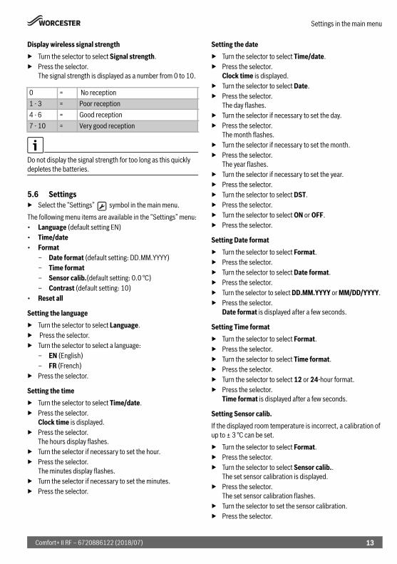
Display wireless signal strength▶ Turn the selector to select Signal strength.▶ Press the selector.
The signal strength is displayed as a number from 0 to 10.
Do not display the signal strength for too long as this quickly depletes the batteries.
5.6 Settings▶ Select the “Settings” symbol in the main menu.The following menu items are available in the “Settings” menu:• Language (default setting EN)• Time/date• Format
– Date format (default setting: DD.MM.YYYY)– Time format– Sensor calib.(default setting: 0.0 °C)– Contrast (default setting: 10)
• Reset all
Setting the language▶ Turn the selector to select Language.▶ Press the selector. ▶ Turn the selector to select a language:
– EN (English)– FR (French)
▶ Press the selector.
Setting the time▶ Turn the selector to select Time/date.▶ Press the selector.
Clock time is displayed.▶ Press the selector.
The hours display flashes.▶ Turn the selector if necessary to set the hour.▶ Press the selector.
The minutes display flashes.▶ Turn the selector if necessary to set the minutes.▶ Press the selector.
Setting the date▶ Turn the selector to select Time/date.▶ Press the selector.
Clock time is displayed.▶ Turn the selector to select Date.▶ Press the selector.
The day flashes.▶ Turn the selector if necessary to set the day.▶ Press the selector.
The month flashes.▶ Turn the selector if necessary to set the month.▶ Press the selector.
The year flashes.▶ Turn the selector if necessary to set the year.▶ Press the selector.▶ Turn the selector to select DST.▶ Press the selector.▶ Turn the selector to select ON or OFF.▶ Press the selector.
Setting Date format ▶ Turn the selector to select Format.▶ Press the selector.▶ Turn the selector to select Date format.▶ Press the selector.▶ Turn the selector to select DD.MM.YYYY or MM/DD/YYYY.▶ Press the selector.
Date format is displayed after a few seconds.
Setting Time format▶ Turn the selector to select Format.▶ Press the selector.▶ Turn the selector to select Time format.▶ Press the selector.▶ Turn the selector to select 12 or 24-hour format.▶ Press the selector.
Time format is displayed after a few seconds.
Setting Sensor calib.If the displayed room temperature is incorrect, a calibration of up to ± 3 °C can be set.▶ Turn the selector to select Format.▶ Press the selector.▶ Turn the selector to select Sensor calib..
The set sensor calibration is displayed.▶ Press the selector.
The set sensor calibration flashes. ▶ Turn the selector to set the sensor calibration.▶ Press the selector.
0 = No reception1 - 3 = Poor reception4 - 6 = Good reception7 - 10 = Very good reception
13Comfort+ II RF – 6720886122 (2018/07)

Settings in the service menu (installer)
Setting the display contrast ▶ Turn the selector to select Format.▶ Press the selector.▶ Turn the selector to select Contrast.▶ Press the selector.▶ The current contrast flashes.▶ Turn the selector to set the desired contrast level between
0 and 20.▶ Press the selector.
Restoring the factory settings (Reset all)Reset all restores the factory settings of all settings in the main menu of the control unit.All adjusted switching times and temperatures for central heating or DHW heating and all other settings must be re-entered.The factory settings can be found under the relevant menu item description.▶ Turn the selector to select Reset all.▶ Press the selector to confirm.
NO flashes.▶ If a reset is required, turn the selector to select YES.▶ Press the selector.
Lines appear one by one on the display until four can be seen briefly. Reset all reappears in the display.
The factory settings of the control unit ( Table 5) have been restored. Every switching time for central heating of DHW heating that was previously adjusted must be reset.
Table 5
6 Settings in the service menu (installer)The following functions are only used by specialists. They are used to install the Comfort+ II RF or for troubleshooting.
Fig. 14 Installer menu display
[1] Heating [2] DHW [3] Holiday [4] Information [5] settings[6] Service menu ▶ Press the menu and keys until the main menu with
service menu is displayed ( Fig. 14).▶ Turn the selector to select the “service menu” symbol.▶ Press the selector.The following menu items are available in the service menu:• System data• Reset all• Heat.circuit• Maintenance
– Fault history– Maintenance
• System info• Radio settings• Weather Comp.The top line of text in the display shows the menu items. Flashing arrows indicate that additional menus are available.
System data▶ Turn the selector to select System data.▶ Press the selector.
HC assignment is displayed.The number 1 appears in the display, i.e. there is only one heating circuit.
▶ Press the key to return to System data.
Switching time 06:30 08:30 16:30 22:30Heating temperature
20 °C 16 °C 21 °C 10 °C
Domestic Hot Water
ON OFF ON OFF
2 3 4 5 61
pmam
0010009673-002
Comfort+ II RF – 6720886122 (2018/07)14

Settings in the service menu (installer)
Restoring the factory settings (Reset all)The Reset all menu item restores the factory settings for all settings in the service menu. The factory settings can be found under the relevant menu item description.▶ Turn the selector to select Reset all.▶ Press the selector.
NO flashes.▶ Turn the selector to select NO or YES.▶ Press the selector.
If YES is selected, the factory settings are restored for all settings in the installer menu. Four lines appear one by one on the display until the reset is complete. If NO is selected, a reset is not performed.
Heat.circuitThis menu item allows the installer/service engineer to set the maximum flow temperature for the heating in order to increase the efficiency of the heating system. The default setting is 85 °C.▶ Turn selector to select Heat.circuit.▶ Press the selector.▶ Press the selector.
Max. flow is displayed.▶ Press the selector.
The temperature flashes.▶ Turn selector to select the required temperature for the
heating system requirements.▶ Press the selector.▶ Press the key to return to Heat.circuit.
Reading out Fault history▶ Turn the selector to select Maintenance.▶ Press the selector.▶ Press the selector to display Boiler faults.
Heat source faults are displayed here and at the heat source. The control unit may be far away from the heat source. It may therefore be helpful to view the faults of the heat source at the control unit.
▶ Press the selector to display the first five faults with fault code and event date. Turn the selector to scroll through the display. If there were no faults, No fault is displayed.
▶ Press key to return to Boiler faults.▶ Turn selector to select Cont. faults.▶ Press the selector to display the first five faults with fault
code and event date. Turn the selector to scroll through the display. If there were no faults, No fault is displayed.
▶ Press key to return to Cont. faults.▶ Press the key, to return to Fault history.▶ Turn the selector to select Maintenance or press key
to return to Maintenance.
Maintenance
Landlord ▶ Call technical customer service to find out how to set the
service display or contact telephone number.
This menu item is only for council housing tenants. It allows a date to be set for annual service/maintenance.The service display Maintenance appears as a reminder 30 days before the scheduled date. A contact telephone number is shown together with service display.The tenant should call this number to arrange a suitable maintenance date with the landlord.If the service display is not cleared or reset by the service engineer, the control unit limits the room temperature 14 days after the maintenance date to the reduced set value set at the device. Otherwise the central heating and DHW functions are set.
System info▶ Turn the selector to select System info.▶ Press the selector to display Install.date.▶ Press the selector to display the installation date.▶ Press the selector to return to Install.date.▶ Turn the selector to select SW controller.▶ Press the selector to display the program version of the
control unit.▶ Press the selector to return to SW controller.▶ Press the key to return to System info.
Radio settings - connecting/disconnecting
The control unit and key are connected at the factory in the delivered condition and detect each other automatically when switching on.If the wireless devices still have to be connected, this must be done at the same time (Key Chapter 7.1).
To connect the wireless devices, both the control unit and key must be disconnected beforehand (Key Chapter 7).▶ Make sure that the control unit is positioned as described in
Chapter 7 and that the wireless signal is not diminished by metal objects nearby.
It is advisable to find a position with good signal strength installing the control unit on the wall.
15Comfort+ II RF – 6720886122 (2018/07)

Key
Once the connection has been established, check the signal strength at the control unit. If the signal strength is low, try another position in the room, until the best possible signal strength is achieved ( Chapter 5.5, page 12).The functions Pairing and Unpairing can be found in the installer menu under Radio settings.To display the installer menu, press menu key and key for at least three seconds.Six symbols appear at the top of the display:• Heating • DHW • Holiday • Information • settings• Installer menu ▶ Turn the selector to select the symbol. ▶ Press the selector to open the service menu.▶ Turn the selector to select Radio settings.▶ Press the selector.▶ Turn the selector to select Unpairing or Pairing .▶ If Pairing is selected, press selector. Pairing is displayed
by a progress bar and the timer starts at 120 s. Once the connection has been established, the timer is cancelled and the number of connected control units appears on the display as confirmation.
-or-▶ If Unpairing is selected, press selector. Unpairing is
indicated by a progress bar. Once the connection has been disconnected, "0" appears as confirmation on the display.
7 KeyThe key is connected to the control unit. Both communicate via wireless signals. The key has a button and an LED to display various operating conditions.
7.1 Connecting/disconnecting the control unit
The control unit and key are connected at the factory in the delivered condition and detect each other automatically when switching on. It is not necessary to connect/disconnect unless there is a problem exists with one or both of the wireless devices.▶ If a defective wireless device is replaced with a new one, the
defective wireless device must be disconnected before the new combination can be connected.
▶ In order to connect/disconnect, both wireless devices must be connected/disconnected.
If a defective wireless device is replaced with a new one, the defective one must be disconnected before the new wireless device can be connected. The new wireless device combination must be connected at the same time.▶ While the control unit is disconnecting, press the button on
the key for longer than ten seconds to disconnect the key. The LED flashes five times in five seconds during the disconnection process.
Once the faulty wireless device has been disconnected, the new wireless device can be mounted and connected.▶ While the control unit is connecting, press the button
(Fig. 15, Pos. [2]) on the key briefly to connect the key.The LED (Fig. 15, Pos. [1]) flashes twice in five seconds while the connection is being established.
Fig. 15 Key
[1] LED on the key (for the LED coding Table 1)[2] Button on key
1 2
0010021545-002
Comfort+ II RF – 6720886122 (2018/07)16

Troubleshooting
Table 6 LED display key
Factory reset▶ To perform a factory reset, press and hold the button on the
key. The LED flashes yellow for five seconds.The restart takes place after two seconds.
8 Troubleshooting If a fault cannot be corrected:▶ Confirm the fault.▶ Faults that are still active are displayed once again the next
time the control unit returns from the idle state.▶ Call an authorised specialist or customer service and give
the fault code and sub-code, as well as the ID number of the user interface.
Table 7 Your contractor must enter the ID no. here.
8.1 Rectify fault
Structure of table headers:code - [cause or fault description].
8.1.1 Faults in the control unit or key
User interfaceIn the event of a fault, a code is displayed.
Table 8
Table 9
Table 10
Table 11
Table 12
Table 13
LED red
LED yellow
LED green
LED off
_ _ _
SET TIME + DATE
OFF
1007 - [no wireless signal]Description ActionNo radio connection between control unit and key.
Check the signal strength and position the control unit in a better place.
1009 - [no wireless signal or connection failed]Description ActionNo radio connection between control unit and key.
Reconnect wireless device.
309x; x=number of heating circuit - [control unit temperature sensor faulty]Description ActionControl unit temperature sensor outside the permissible range.
Replace control unit.
1004 - [fault in other control unit]Description ActionAnother control unit in the system has developed a fault.
Check other control units in the system for faults.
1010 - [no communication with heat source via EMS-BUS]Description ActionNo communication, although heat source is compatible with EMS.
Replace EMS connections/interfaces.
1009 - [not connected]Description ActionWireless device is not connected.
Disconnect and reconnect all wireless devices.
17Comfort+ II RF – 6720886122 (2018/07)

Maintenance
Table 14
Table 15
Table 16
Table 17
Table 18
Table 19
KeyThe LED flashes every second if a fault display is present (e.g. no EMS connection).
Table 20
9 MaintenanceThe control unit and key require no maintenance other than changing the batteries in the control unit.The casing can be cleaned with a dry cloth. Do not use cleaning agents or solutions.
9.1 Replace batteries of control unitAs soon as the symbol for weak batteries is displayed in normal operation, the batteries must be replaced within the next 60 days, otherwise the programmed settings are lost.▶ Replace the batteries with new ones of the same type: LR6/
AA 1.5 V Alkaline.
Fig. 16 Low batteries display
Access to the batteriesTo release the control unit from the wall socket:1. Insert a flat-head screwdriver into the recess on the
underside of the control unit.2. Gently turn the screwdriver, until the locking device is
open.3. Release the control unit from the wall socket.
[blank display or low battery symbol]Description ActionBatteries are used up. Replace batteries.
1017- [system pressure too low]Description ActionSystem pressure is too low. Fill system.
207 - [low system pressure]Description ActionSystem pressure is low. Fill system.
1070 - [maintenance due on ...]Description ActionMaintenance is next due on <dd.mm.yyyy>. Please call your installer, tel. <tel nr>
Inform the installer that maintenance should be carried out within the next 30 days
1071 - [maintenance now due]Description ActionMaintenance is now due. Please call your installer, tel. <tel nr>
Inform the installer that maintenance should be carried out
1072 - [maintenance overdue]Description ActionMaintenance is overdue. Please call your installer, tel. <tel nr>
Inform the installer that maintenance is 14 days overdue
[LED flashes once per second]Description ActionLocal program faultNo fault in the heat source but probably loss of the wireless signal to at least one control unit.
Check the control units for faults.
0010009674-002
1
pmam
Comfort+ II RF – 6720886122 (2018/07)18

Product data for energy consumption
Replace batteries▶ Replace used batteries with new ones of the same
type (AA).▶ Ensure that the + pole of the battery is inserted in the
+ pole of the battery compartment.▶ Fit the control unit into the wall socket: first insert into the
lugs [1] at the top and then latch the underside into place.
CAUTION:
Risk of explosion if the battery is replaced with an incorrect type.▶ Use specified batteries only.
Fig. 17 Replace batteries
10 Product data for energy consumptionThe product data specified comply with the requirements of EU Regulation No. 811/2013 as a supplement to Ecodesign Directive 2017/1369/EU. The class of the temperature controller is required to calculate the central heating energy efficiency of an integrated system and is for this reason incorporated into the system data sheet.
Table 21 Product data for the energy efficiency of the user interface
Delivery condition adjustable1) Classification of the user interface according to EU
Regulation 811/2013 for the identification of integrated systems
2) Contribution to seasonal energy efficiency of central heating in %
11 Simplified EU Declaration of Conformity regarding radio equipment
Bosch Thermotechnik GmbH hereby declares, that the Comfort+ II RF product described in these instructions complies with the Directive 2014/53/EU.The complete text of the EU Declaration of Conformity is available on the Internet: worcester-bosch.co.uk.
12 Specifications
Table 22 Wireless technology in Comfort+ II RF and key
Function of control unit Class1) [%]1),2)
Comfort+ II RF & Key
Room temperature-dependent, modulating
V 3.0
Weather-compensated VI 4.0 l
6720
8109
65-1
0.1W
o
+
+
1
Transmission protocol (wireless) X3D-CTransmission frequency 868.00 MHzBand width frequency 868.7 – 869.2 MHzMaximum transmitting capacity 10 mWInstallation height -5 – 1800Atmospheric pressure 780 – 10505Operating temperature 0 – 60 °CStorage temperature -20 – 85 °CRelative humidity 23 °C 0 – 80%Relative humidity 40 °C 0 – 93%IP rating IP20, IPX4D
according to DIN 40050
Category of receiver 2Vibration EN ISO 1335
ASTM 4728Batteries required AAA/AABattery service life 2 yearsTemperature of ball test 75 °CDegree of pollution 2
19Comfort+ II RF – 6720886122 (2018/07)

Environmental protection/disposal
13 Environmental protection/disposalUsed electrical and electronic appliances
Electrical or electronic devices that are no longer serviceable must be collected separately and sent for environmentally compatible recycling (in accordance with the European Waste Electrical and Electronic Equipment Directive).
To dispose of old electrical or electronic devices, you should use the return and collection systems put in place in the country concerned.Batteries must not be disposed together with your household waste. Used batteries must be disposed of in local collection systems.
Comfort+ II RF – 6720886122 (2018/07)20

Overview Main menu
14 Overview Main menuFunctions marked with are only available if an outside temperature sensor is installed.The menu items are displayed in the sequence listed below.
Heating
– Time program– Mo-Fr– Sat-Sun– Monday– Tuesday– Wednesday– Thursday– Friday– Saturday– Sunday
Hot water
– Time program– Mo-Fr– Sat-Sun– Monday– Tuesday– Wednesday– Thursday– Friday– Saturday– Sunday
– Reset DHW Clock Program– No– Yes
– Temperature
Holiday
– Holiday prog.– Set Date– Holi. temp adj
Info
– System Pressure– Outdoor temp.– DHW
– Actual temp– Signal strength
– Energy Consumption– CH gas cons.– CH elec cons.– DHW gas cons.– DHW elec cons.
Settings
– Language1)
– Time/date– Clock time– Date– DST
– Format– Date format– Time format– Sensor calib.– Contrast
– Reset all
Installer
– System data– HC assignment
– Reset all– Heat.circuit
– Max. flow– Heat. Algorithm
– Maintenance– Fault history– Maintenance
– System info– Install.date– SW controller– SW base station
– Radio settings– Pairing – Unpairing
– Weather Comp.– Type circuit– Max. flow– Max outd. temp.– Des. flow temp.– Base flow temp.– Room Influence
1) Set language.
21Comfort+ II RF – 6720886122 (2018/07)


Bosch Thermotechnology Ltd.Cotswold Way, WarndonWorcester WR4 9SWUnited KingdomTel. 0330 123 9559worcester-bosch.co.uk
TECHNICAL SUPPORT: 0330 123 3366RENEWABLE SUPPORT: 0330 123 9229CONTROLS AND CONNECTIVITY TEAM: 0330 123 3641APPOINTMENTS: 0330 123 9339SPARES: 0330 123 9779LITERATURE: 0330 123 9119TRAINING: 0330 123 0166SALES: 0330 123 9669