Embed Size (px)
Citation preview
Installation and Operating InstructionsEngine Performance Controller
Form EPC-250 IOI 9-14

EPC-250 IOI 9-14 All rights reserved © ALTRONIC, LLC 2014 2
1.0 SYSTEM DESCRIPTION 1.1 The Altronic EPC-250 engine performance controller is a device designed to
maximize engine performance and efficiency. The controller is specifically designed to control ignition timing and air/fuel ratio on spark-ignited, turbo-charged, fuel-injected gas engines allowing for the total replacement of tradi-tional pneumatic control systems. The EPC-250 is intended as a direct field replacement for the existing legacy EPC-200 with little to no wiring retrofit. The user-friendly interface allows easy configuration of the legacy EPC-200 functionality thru a touch screen display. Visual representation of control parameters via trending can also be displayed on the touch screen to aid in engine tuning.
1.2 In addition to Engine RPM, up to four other analog inputs can be used as control
variables. The additional four analog inputs can be scaled to represent desired engineering units.
1.3 The EPC-250 operator interface is built around an 8.4" TFT 23K VGA 640 x 480 pixel LCD display high performance core with integrated function-ality. The application’s configuration is stored in a non-volatile memory (32MB flash). The EPC-250 incorporates a SD Memory card to increase memory capacity, collect trending and data logging information, and store larger con-figuration files.
1.4 EPC-250 TYPICAL CONTROL FUNCTIONS
A. IGNITION TIMING RETARD Ignition Timing Retard vs. Engine Speed Ignition Timing Retard vs. Fuel Manifold Pressure Ignition Timing Retard vs. Air Manifold Pressure Ignition Timing Retard vs. Air Manifold Temperature Ignition Timing Retard vs. Pilot Manifold PressureIgnition Timing Retard vs. Exhaust Manifold Temperature
The operating values for the functions above are calculated separately accord-ing to user entered curves, and the combined net effect is implemented by the EPC-250 Controller in a PID format.
B. AIR/FUEL RATIOAir Manifold Pressure vs. Fuel Manifold Pressure Air Manifold Pressure vs. Engine Speed Air Manifold Pressure vs. Exhaust TemperatureAir Manifold Pressure vs. Pilot Manifold PressureAir Manifold Pressure vs. Air Manifold Temperature
The operating values for the functions above are calculated separately accord-ing to user entered curves, and the combined net effect is implemented by the EPC-250 Controller.
C. AUXILIARY OUTPUT FUNCTIONS (typical) Spare ................................................................................ (0utput 1) Speed OP2 ........................................................................ (0utput 2) Speed OP3 ........................................................................ (0utput 3) Timer 1 ............................................................................. (0utput 4) Timer 2 ............................................................................. (0utput 5) Over Crank ........................................................................ (0utput 6) Spare ................................................................................ (0utput 7) Fault ................................................................................. (0utput 8)
WARNING: Deviation from these instructions may lead to improper en-gine/machine operation which could cause personal injury to operators or other nearby personnel.
EPC-250 IOI 9-14 All rights reserved © ALTRONIC, LLC 2014 3
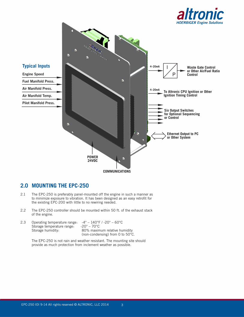
2.0 MOUNTING THE EPC-2502.1 The EPC-250 is preferably panel-mounted off the engine in such a manner as
to minimize exposure to vibration. It has been designed as an easy retrofit for the existing EPC-200 with little to no rewiring needed.
2.2 The EPC-250 controller should be mounted within 50 ft. of the exhaust stack of the engine.
2.3 Operating temperature range: -4° – 140°F / -20° – 60°C Storage temperature range: -20° – 70°C Storage humidity: 80% maximum relative humidity (non-condensing) from 0 to 50°C.
The EPC-250 is not rain and weather resistant. The mounting site should provide as much protection from inclement weather as possible.
Waste Gate Control or Other Air/Fuel Ratio Control
4–20mA
To Altronic CPU Ignition or Other Ignition Timing Control
Six Output Switches for Optional Sequencing or Control
Ethernet Output to PC or Other System
4–20mA
POWER24VDC
COMMUNICATIONS
Typical Inputs
Engine Speed
Fuel Manifold Press.
Air Manifold Press.
Air Manifold Temp.
Pilot Manifold Press.
EPC-250 IOI 9-14 All rights reserved © ALTRONIC, LLC 2014 4
3.0 WIRING3.1 Power When replacing an EPC-200, remove the 3-pin power terminal from the device
and plug it into the power input terminal of the new EPC-250. Power require-ment is 24Vdc (48 watt max.).
The EPC-250 is designed to accept the Legacy EPC-200 wiring input termi-nation, which provides an easy swap of the two 20-pin terminals with their pre-wire arrangement.
Proper panel/system ground must be implemented to provide an alternative path for fault current flow, and limit the voltage-rise induced on powered cir-cuits, typically via lightning, welding, voltage spikes, or unintentional contact with higher-voltages.
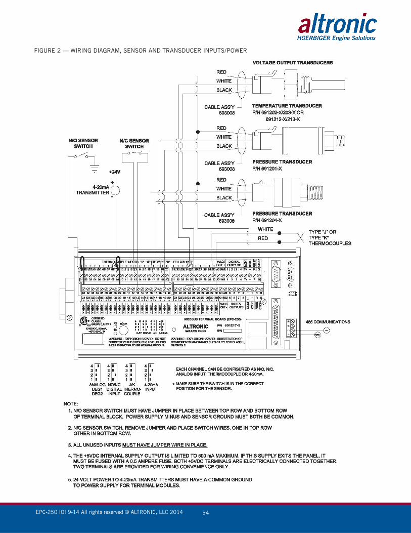
3.2 Discrete Inputs Sensor Wiring
Normally-open (N/O) sensors are wired with one wire to the bot-tom terminal strip of the respective sensor number and the other to engine ground, which should be the same as power minus (−). A short jumper from the bottom terminal to the top terminal must be connected for normally-open sensors (see wiring diagrams).
Normally-closed (N/C) sensors are wired with one wire to the bottom terminal strip and the other to the top terminal strip of the respective sensor number. Note that the short jumper wire must be removed.
Use a wire size between 16 AWG (max.) and 24 AWG (min.) to connect the sensor switches to the terminal strip connector. Strip the insulation back 3/8" and twist the exposed wires tightly together. Insert the exposed wire complete-ly into the terminal strip and securely tighten the clamping screw. Wires run-ning to sensor switches must be in good condition or replaced with new wires. When running wires, take care not to damage the insulation and take precau-tions against later damage from vibration, abrasion, or liquids in conduits. An explosion-proof conduit is not required. Wires should be protected from damage by running them in a protective conduit or in sheaths when required. In addition, it is essential that the following practices be adhered to:
A. Never run sensor wires in the same conduit with ignition wiring or other high energy wiring such as the AC line power.
B. Keep secondary wires to spark plugs and other high voltage wiring at least eight inches (200mm) away from sensor and sensor wiring.
C. If it becomes necessary to check sensor switch, first DISCONNECT the sen-sor from the terminal strip of the modbus terminal board. Applying voltage to the Modbus terminal board through the sensor leads may damage the device. The area should be tested as non-hazardous before such testing commences.
3.3 Analog Sensor Wiring For each analog monitored point, select a transducer—either an Altronic pres-
sure or temperature transducer listed above or one that outputs a signal in the range of 0 to 5Vdc or 0 to 25mA. Mount as described above. Use cable as-sembly 693008-x or similar to wire transducer to the Modbus terminal board. An internal 5 volt sensor supply (500mA max.) is available to power the Altronic transducers; see wiring diagrams. If the 5 volt sensor supply exits the panel, it must be fused with a 0.5 ampere fuse. If 24Vdc powered sensors are used, the 24 volt supply to them must be fused appropriately. Take caution not to damage the insulation when installing and take precautions against later damage from vibration, abrasion, or liquids in conduits.
3.4 Thermocouples and Thermocouple Extension Wire Only ungrounded type J or K thermocouples may be used. Use thermocouple
extension wire of the same type as the thermocouple probe to connect to the terminal module. Use stranded thermocouple wire having a moisture-resistant insulation such as PVC; for higher ambient temperatures, Teflon- or fiber-insu-
Note: Voltage and current supplied must be sufficient to operate all transducers used in the installation.
NOTE: A power supply with an NEC Class 2 or Limited Power Source (LPS) and SELV rating is to be used. This type of power supply providesisolation to accessible circuits from hazardous voltage levels generatedby a mains power supply due to single faults. SELV is an acronym for“safety extra-low voltage.” Safety extra-low voltage circuits shallexhibit voltages safe to touch both under normal operating conditionsand after a single fault, such as a breakdown of a layer of basicinsulation or after the failure of a single component has occurred.
Note: The (+) and (-) terminals of theEPC-250 are polarity sensitive.
IMPORTANT: Pressure transducers will withstand overloads as high as 1.5 times rated pressure. If the overload rating is exceeded, failure may occur. Pressure fluctuations occur in most reciprocating systems; pick the transducer with a rating high enough to prevent overload by peak pressures of pulsations. It is recommended that a pressure snubber be used which will reduce the peak pressure applied to the transducer. The life of the transducer will be extended with the use of a snubber or pulsation dampener.
IMPORTANT: Do not exceed the absolute maximum rating of the transducers, 350°F (176°C) for the 691202/203-300 or 450°F (232°C) for the 691212/213-450. Care should be taken to protect the wiring and connectors from contact with hot surfaces.

EPC-250 IOI 9-14 All rights reserved © ALTRONIC, LLC 2014 5
lated thermocouple wire is recommended. To ensure that an accurate signal is transmitted to the device, avoid any added junctions, splices and contact with other metals. On unused channels, leave the small jumper wire supplied with the system in place. Be careful not to damage the insulation when installing and take precautions against later damage from vibration, abrasion, or liquids in conduits. In addition, it is essential that the following practices be adhered to:
A. Never run sensor wires in the same conduit with ignition wiring or other high energy wiring such as AC line power.
B. Keep secondary wires to spark plugs and other high voltage wiring at least eight inches (200mm) away from sensor and sensor wiring.
3.5 RS-485 Communications The EPC-250 incorporates a half-duplex RS-485 port via the HMI which is
Modbus RTU slave compliant with the Modbus terminal board.
NODE: 1BAUD RATE: 38.4KDATA BITS: 8PARITY: NoSTOP BITS: 1Baud Rate, Data Bits, Parity, and Stop Bits are fixed and cannot be changed.
The node number indicated by the mechanical switch on the Modbus Terminal Board must be set to position 1.
3.6 HMI Ethernet Communications The IP network configuration of the EPC-250 is edited via the network icon in
the navigation pane. The pane has been purposely configured and is not ac-cessible for security purposes. If a specific network configuration is required it should be requested during ordering.
Ethernet communication can be established at either 10 Base-T or 100 Base-TX. The device’s RJ45 jack is wired as a NIC (Network Interface Card). For example, when wiring to a hub or switch use a straight-through cable, but when connecting to another NIC use a crossover cable. A default Ethernet port has been dedicated with the following configuration:
PROTOCOL: Modbus TCP/IP SlavePORT MODE: Manual ConfigurationIP ADDRESS: 192.168.254.1NETWORK MASK: 255.255.255.0GATEWAY: 0.0.0.0
A specific Network configuration can be program on request when ordering a unit.
EPC-250 IOI 9-14 All rights reserved © ALTRONIC, LLC 2014 6
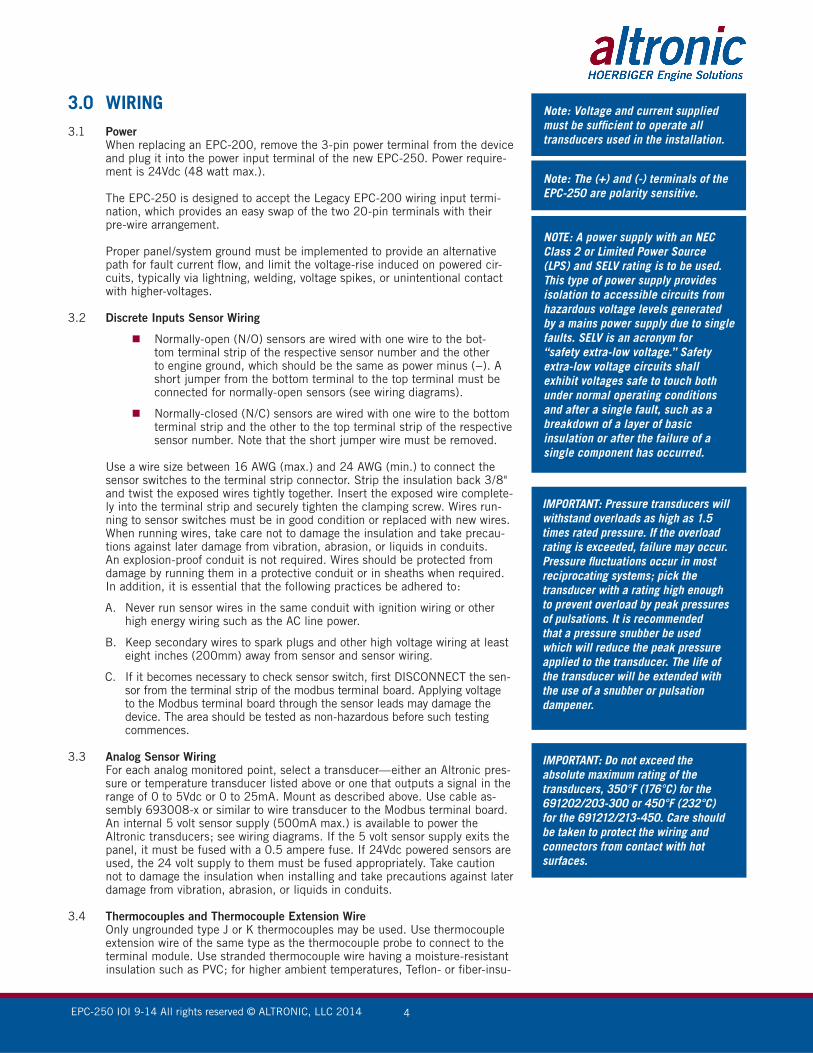
3.7 Touch Icons There are three soft keys below the display area that have been programmed
to a designated page. The home icon is the Main Menu page, Blue dash Air PID SETPOINTS page and Exclamation ICon takes user to the Alarms page.
3.8 SD Memory Card SD slot accepts standard capacity cards up to 2Gbyte. SD Memory cards can
be used for configuration transfers, larger configurations, data logging and trending. They are available at most computer and office supply retailers.
4.0 TERMINAL BOARD4.1 The Modbus Terminal Board (MTB) is the input card to the HMI. Pressure and
temperature input signals are accept via the two terminal connections for each Channel. Each channel is predetermined by the wiring schematic of figure 5. Sensors 2, 3, 7 and 27 are pre-wired based on the Legacy EPC-200 existing terminal connection. All other sensors will be wired directly to the MTB termi-nal connection. These sensors can be used for either a normally-open switch, normally-closed switch, or analog inputs including K- or J-type thermocouples. These are listed as channels 01–30. They accept industry-standard transducer signals in the range of 0-5Vdc.
4.2 The Modbus Terminal Board is designed to operate with industry-standard voltage—or current-amplified—output transducers in the range of 0-5Vdc or 0-25mA. Four series of transducers are available from Altronic: pres-sure transducers (691201-x, 691204-x) and temperature transducers (691202/203- 300, 691212/213-450).
4.3 Pressure Transducers The pressure transducers (Altronic P/N 691201-x and P/N 691204-x) are
packaged in a rugged, sealed case with a NPT pressure port, a corrosion resis-tant media cavity, and a Metri-Pack connector. The ranges available are 0-15, 0-25, 0-50, 0-100, 0-300, 0-500, 0-1000, 02000, and 0-5000PSIG for the 691201-x series; and 0-15, 0-20, 0-30, 0-50, 0-100, 0-300, 0-500PSIA for the 691204-x series. All have an overload rating of 1.5 times full scale with-out damage. The three wires from the transducer are: +5 volt excitation, +0.5 to 4.5 volt output, and minus return.
Note: Do not remove or insert the SD Memory card while power is applied. A card with a larger capacity may be used. Cards MUST be formatted to 2GB and use the FAT 16 file system. The card must remain inserted while operating the EPC-250.
EPC-250 IOI 9-14 All rights reserved © ALTRONIC, LLC 2014 7
4.4 Temperature Transducer The temperature transducers (Altronic P/N 691202-300, 691203-300 with
a temperature measurement range of +5 to 300°F and the 691212-450, 691213-450 with a temperature range of -40 to +450°F) are packaged in a sealed, stainless steel housing with a 5/8" 18 UNF threaded body, and a Metri-Pack connector. During configuration the standard calibration for the 691202/203-300 sensor is selected as dEG1 and the standard calibration for the 691212/213-450 is selected by choosing dEG2. The three wires from the transducer are: +5 volt excitation, temperature output voltage, and minus re-turn. These wires connect directly to the terminal board using cable assembly P/N 693008-x.
4.5 Thermocouple Inputs The terminal board can accept industry standard type J or K thermocouples.
Automatic cold junction compensation is built-in. The units can be configured to °F or °C. Both a high and low setpoint is associated with each channel. The monitor can read type J thermocouples between -76°F and +1382°F (-60°C and +750°C) and type K thermocouples between -76°F and +1472°F (-60°C and +800°C).
4.6 N/O and N/C Inputs The inputs can also accept standard normally-open and normally-closed con-
tacts. Refer to figure 2 for proper wiring of these types of inputs.
4.7 4-20mA Inputs The terminal board can accept 4-20mA inputs by selecting the internally con-
nected 200 ohm resistors, creating a termination voltage of .8 to 4.0 volts. The jumper wires between the + and – terminals for that channel must be connected for proper operation.
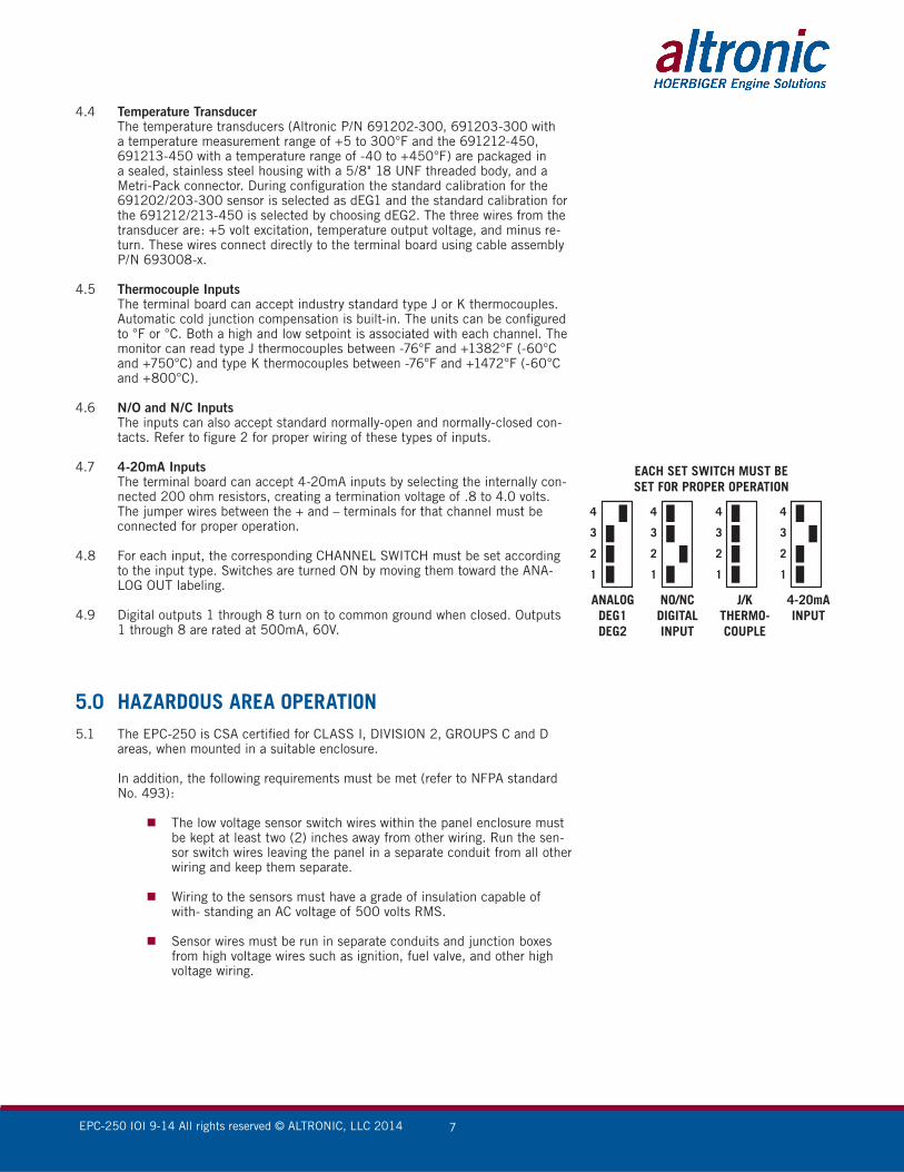
4.8 For each input, the corresponding CHANNEL SWITCH must be set according to the input type. Switches are turned ON by moving them toward the ANA- LOG OUT labeling.
4.9 Digital outputs 1 through 8 turn on to common ground when closed. Outputs 1 through 8 are rated at 500mA, 60V.
5.0 HAZARDOUS AREA OPERATION5.1 The EPC-250 is CSA certified for CLASS I, DIVISION 2, GROUPS C and D
areas, when mounted in a suitable enclosure.
In addition, the following requirements must be met (refer to NFPA standard No. 493):
The low voltage sensor switch wires within the panel enclosure must be kept at least two (2) inches away from other wiring. Run the sen-sor switch wires leaving the panel in a separate conduit from all other wiring and keep them separate.
Wiring to the sensors must have a grade of insulation capable of with- standing an AC voltage of 500 volts RMS.
Sensor wires must be run in separate conduits and junction boxes from high voltage wires such as ignition, fuel valve, and other high voltage wiring.
4
3
2
1
4
3
2
1
4
3
2
1
4
3
2
1
EACH SET SWITCH MUST BESET FOR PROPER OPERATION
ANALOGDEG1DEG2
NO/NCDIGITALINPUT
J/KTHERMO-COUPLE
4-20mAINPUT
EPC-250 IOI 9-14 All rights reserved © ALTRONIC, LLC 2014 8
6.0 SEQUENCE OF OPERATION6.1 Apply power to unit. The display will automatically revert to the OVERVIEW
page as the home page on start-up.
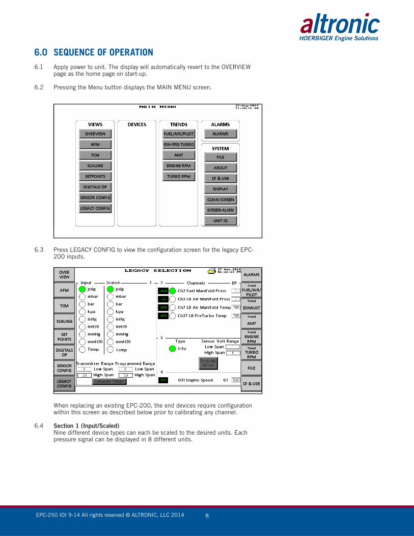
6.2 Pressing the Menu button displays the MAIN MENU screen.
6.3 Press LEGACY CONFIG to view the configuration screen for the legacy EPC-200 inputs.
When replacing an existing EPC-200, the end devices require configuration within this screen as described below prior to calibrating any channel.
6.4 Section 1 (Input/Scaled) Nine different device types can each be scaled to the desired units. Each
pressure signal can be displayed in 8 different units.

EPC-250 IOI 9-14 All rights reserved © ALTRONIC, LLC 2014 9
6.5 Transmitter Range Each input channel requires a low and high span of the transmitter range and
is a user input for the program to calculate the range for each designated input channel. Ensure that the units and span matches the selected device. The cal-culated range value will be used to calculate the desired units to be displayed. The displayed value of the programmed range is the calculated range based on the units selected. This value is also an aid to calibrating the sensor span in the calibration page.
6.6 Section 2 (Channels) Allows the user to select the channel to be configured, with the option of add-
ing decimal points to the value. A calibration pop-up window is available when selecting the desired channel value; it allows adjusting of the Zero and Span of the transmitter for each of the four channels.
The Up/Down arrows can be used to approach the desired span value. If a precise value is desired, click the input box for that signal and enter the value.
6.7 Decimal Point (DP) Used to set the number of decimal places to display.
6.8 Section 3 (Type) Legacy configuration will only allow for a 1-5V transmitter range, imitating the
limitations of the EPC-200. A Sensor Volt Range span is available for custom voltage devices.
6.9 Section 4 (Engine Speed) Displays the actual RPM value and allows the user to enter the gear tooth
count or pulses per revolution for the engine.
6.10 From the Menu button, select AFM (Air/Fuel Menu) to display the Air/Fuel ratio curve configuration. By default the program assumes the PID page as the home position. In addition to the PID control page, five supplementary control functions can be selected.
6.11 In addition to the legacy sensor configuration page, a second option is available that allows two addition sensor type to be use. The EPC-250 accepts .5–4.5V and 4–20mA inputs which must be programmed within this configuration page. Before the input can be programmed as 4-20mA it must be selected on the terminal board by the CHANNEL SWITCH that internally connects a 200
EPC-250 IOI 9-14 All rights reserved © ALTRONIC, LLC 2014 10
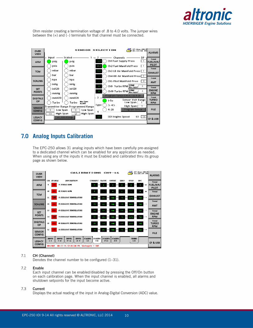
Ohm resister creating a termination voltage of .8 to 4.0 volts. The jumper wires between the (+) and (–) terminals for that channel must be connected.
7.0 Analog Inputs Calibration
The EPC-250 allows 31 analog inputs which have been carefully pre-assigned to a dedicated channel which can be enabled for any application as needed. When using any of the inputs it must be Enabled and calibrated thru its group page as shown below.
7.1 CH (Channel) Denotes the channel number to be configured (1–31).
7.2 Enable Each input channel can be enabled/disabled by pressing the Off/On button
on each calibration page. When the input channel is enabled, all alarms and shutdown setpoints for the input become active.
7.3 Current Displays the actual reading of the input in Analog-Digital Conversion (ADC) value.
EPC-250 IOI 9-14 All rights reserved © ALTRONIC, LLC 2014 11
7.4 Slope To properly understand how to configure the channel when using a none Stan-
dard (Altronic Sensor), it is first necessary to know how the sensor relationship between voltage and displayed value (pressure, temperature, other) works.
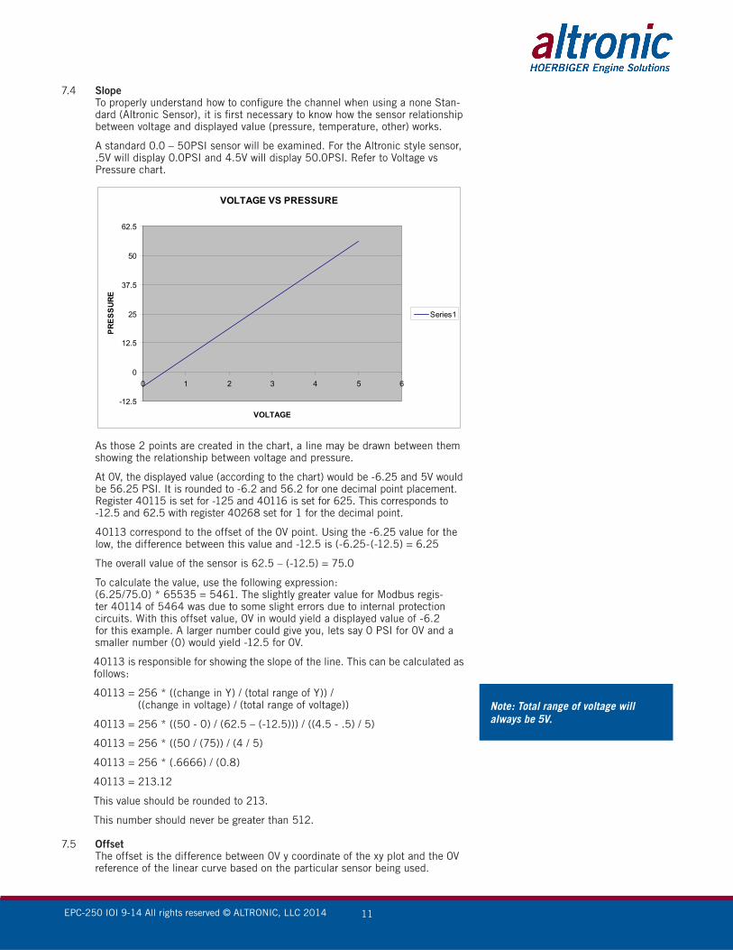
A standard 0.0 – 50PSI sensor will be examined. For the Altronic style sensor, .5V will display 0.0PSI and 4.5V will display 50.0PSI. Refer to Voltage vs Pressure chart.
As those 2 points are created in the chart, a line may be drawn between them showing the relationship between voltage and pressure.
At 0V, the displayed value (according to the chart) would be -6.25 and 5V would be 56.25 PSI. It is rounded to -6.2 and 56.2 for one decimal point placement. Register 40115 is set for -125 and 40116 is set for 625. This corresponds to -12.5 and 62.5 with register 40268 set for 1 for the decimal point.
40113 correspond to the offset of the 0V point. Using the -6.25 value for the low, the difference between this value and -12.5 is (-6.25-(-12.5) = 6.25
The overall value of the sensor is 62.5 – (-12.5) = 75.0
To calculate the value, use the following expression: (6.25/75.0) * 65535 = 5461. The slightly greater value for Modbus regis-
ter 40114 of 5464 was due to some slight errors due to internal protection circuits. With this offset value, 0V in would yield a displayed value of -6.2 for this example. A larger number could give you, lets say 0 PSI for 0V and a smaller number (0) would yield -12.5 for 0V.
40113 is responsible for showing the slope of the line. This can be calculated as follows:
40113 = 256 * ((change in Y) / (total range of Y)) / ((change in voltage) / (total range of voltage))
40113 = 256 * ((50 - 0) / (62.5 – (-12.5))) / ((4.5 - .5) / 5)
40113 = 256 * ((50 / (75)) / (4 / 5)
40113 = 256 * (.6666) / (0.8)
40113 = 213.12
This value should be rounded to 213.
This number should never be greater than 512.
7.5 Offset The offset is the difference between 0V y coordinate of the xy plot and the 0V
reference of the linear curve based on the particular sensor being used.
VOLTAGE VS PRESSURE
-12.5
0
12.5
25
37.5
50
62.5
0 1 2 3 4 5 6
VOLTAGE
PRES
SURE
Series1
Note: Total range of voltage will always be 5V.
EPC-250 IOI 9-14 All rights reserved © ALTRONIC, LLC 2014 12
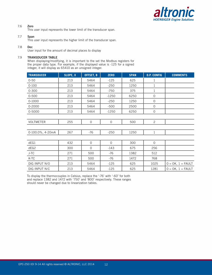
7.6 Zero This user input represents the lower limit of the transducer span.
7.7 Span This user input represents the higher limit of the transducer span.
7.8 Dec User input for the amount of decimal places to display
7.9 TRANSDUCER TABLE When displaying/modifying, it is important to the set the Modbus registers for
the proper data type. For example, if the displayed value is -125 for a signed integer, it will display as 65410 as an unsigned integer.
TRANSDUCER SLOPE, X OFFSET, B ZERO SPAN D.P. CONFIG COMMENTS
0-50 213 5464 -125 625 1
0-100 213 5464 -250 1250 1
0-300 213 5464 -750 375 1
0-500 213 5464 -1250 6250 0
0-1000 213 5464 -250 1250 0
0-2000 213 5464 -500 2500 0
0-5000 213 5464 -1250 6250 0
VOLTMETER 255 0 0 500 2
0-100.0%, 4-20mA 267 -76 -250 1250 1
dEG1 432 0 0 300 0
dEG2 300 0 -143 675 256
J-TC 271 500 -76 1382 512
K-TC 271 500 -76 1472 768
DIG INPUT N/O 213 5464 -125 625 1025 0 = OK, 1 = FAULT
DIG INPUT N/C 213 5464 -125 625 1281 0 = OK, 1 = FAULT
To display the thermocouples in Celsius, replace the ‘-76’ with ‘-60’ for both and replace 1382 and 1472 with ‘750’ and ‘800’ respectively. These ranges should never be changed due to linearization tables.
EPC-250 IOI 9-14 All rights reserved © ALTRONIC, LLC 2014 13
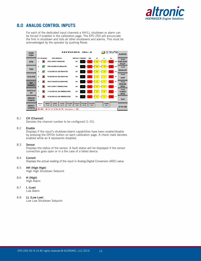
8.0 ANALOG CONTROL INPUTS For each of the dedicated input channels a HH/LL shutdown or alarm can
be forced if enabled in the calibration page. The EPC-250 will annunciate the first in shutdown and lists all other shutdowns and alarms. This must be acknowledged by the operator by pushing Reset.
8.1 CH (Channel) Denotes the channel number to be configured (1–31).
8.2 Enable Displays if the input’s shutdown/alarm capabilities have been enable/disable
by pressing the Off/On button on each calibration page. A check mark denotes enabled while an X represents disabled.
8.3 Sensor Displays the status of the sensor. A fault status will be displayed if the sensor
connection goes open or in a the case of a failed device.
8.4 Current Displays the actual reading of the input in Analog-Digital Conversion (ADC) value.
8.5 HH (High High) High High Shutdown Setpoint
8.6 H (High) High Alarm
8.7 L (Low) Low Alarm
8.8 LL (Low Low) Low Low Shutdown Setpoint
EPC-250 IOI 9-14 All rights reserved © ALTRONIC, LLC 2014 14
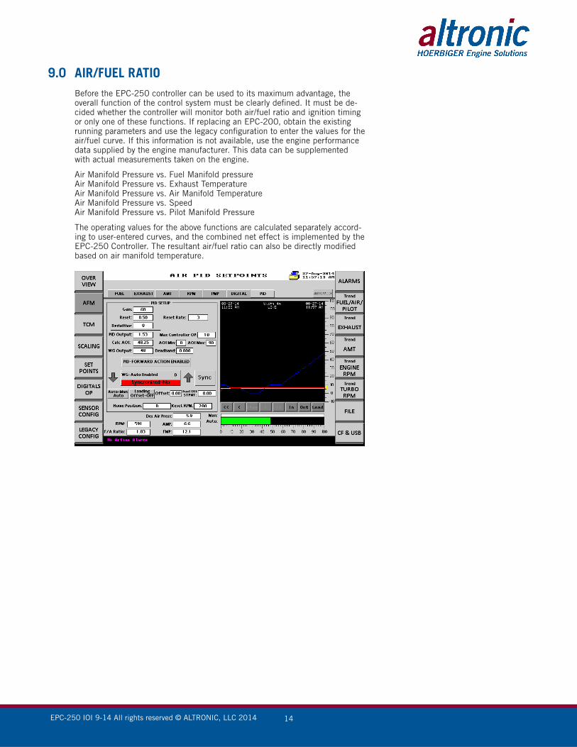
9.0 AIR/FUEL RATIO Before the EPC-250 controller can be used to its maximum advantage, the
overall function of the control system must be clearly defined. It must be de-cided whether the controller will monitor both air/fuel ratio and ignition timing or only one of these functions. If replacing an EPC-200, obtain the existing running parameters and use the legacy configuration to enter the values for the air/fuel curve. If this information is not available, use the engine performance data supplied by the engine manufacturer. This data can be supplemented with actual measurements taken on the engine.
Air Manifold Pressure vs. Fuel Manifold pressure Air Manifold Pressure vs. Exhaust Temperature Air Manifold Pressure vs. Air Manifold Temperature Air Manifold Pressure vs. Speed Air Manifold Pressure vs. Pilot Manifold Pressure
The operating values for the above functions are calculated separately accord-ing to user-entered curves, and the combined net effect is implemented by the EPC-250 Controller. The resultant air/fuel ratio can also be directly modified based on air manifold temperature.

EPC-250 IOI 9-14 All rights reserved © ALTRONIC, LLC 2014 15
9.1 Air/fuel ratio is controlled by regulating the air/fuel pressure ratio. A waste gate (by-pass valve), in parallel with the turbocharger, is opened or closed to decrease or increase the air manifold pressure. The desired air manifold pres-sure is a function mainly of fuel pressure. The actual measured air manifold pressure is compared to the desired calculated value and a signal (4-20mA) is sent to the waste gate to compensate in the proper direction.
When replacing an EPC-200, enter the existing three point values of the air/
fuel curve by pressing the Legacy Curve button.
All the performance curves are entered into the EPC-250 Controller simply by entering the (x,y) coordinates of each point of the seven line segments. In the legacy configuration Channels 67 and 68 correspond to the first point (x = fuel, y = air), Channels 69 and 70 automatically become the fourth line seg-ment, and Channels 71 and 72 determine the end point of the curve. Pressing the Calculate button automatically calculates the curve using the three points of the 3-line segment of the legacy EPC-200 application and generates the the required coordinates to complete the linear 7-segment curve. The air/fuel ratio for that particular line segment is also calculated for each segment which can be manually adjusted by clicking on the desired value. The program also has the capability of linearizing the curve based on two known values
EPC-250 IOI 9-14 All rights reserved © ALTRONIC, LLC 2014 16
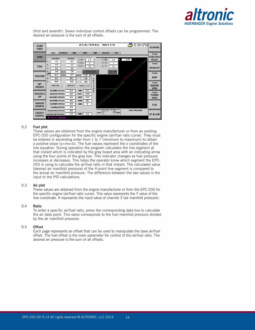
(first and seventh). Seven individual control offsets can be programmed. The desired air pressure is the sum of all offsets.
9.2 Fuel plot These values are obtained from the engine manufacturer or from an existing
EPC-200 configuration for the specific engine (air/fuel ratio curve). They must be entered in ascending order from 1 to 7 (minimum to maximum) to obtain a positive slope (y=mx+b). The fuel values represent the x coordinates of the line equation. During operation the program calculates the line segment at that instant which is indicated by the gray boxed area with an indicating arrow using the four points of the gray box. This indicator changes as fuel pressure increases or decreases. This helps the operator know which segment the EPC-250 is using to calculate the air/fuel ratio in that instant. The calculated value (desired air manifold pressure) of the 4-point line segment is compared to the actual air manifold pressure. The difference between the two values is the input to the PID calculations.
9.3 Air plot These values are obtained from the engine manufacturer or from the EPC-200 for
the specific engine (air/fuel ratio curve). This value represents the Y value of the line coordinate. It represents the input value of channel 3 (air manifold pressure).
9.4 Ratio To enter a specific air/fuel ratio, press the corresponding data box to calculate
the air data point. This value corresponds to the fuel manifold pressure divided by the air manifold pressure.
9.5 Offset Each page represents an offset that can be used to manipulate the base air/fuel
offset. The fuel offset is the main parameter for control of the air/fuel ratio. The desired air pressure is the sum of all offsets.
EPC-250 IOI 9-14 All rights reserved © ALTRONIC, LLC 2014 17
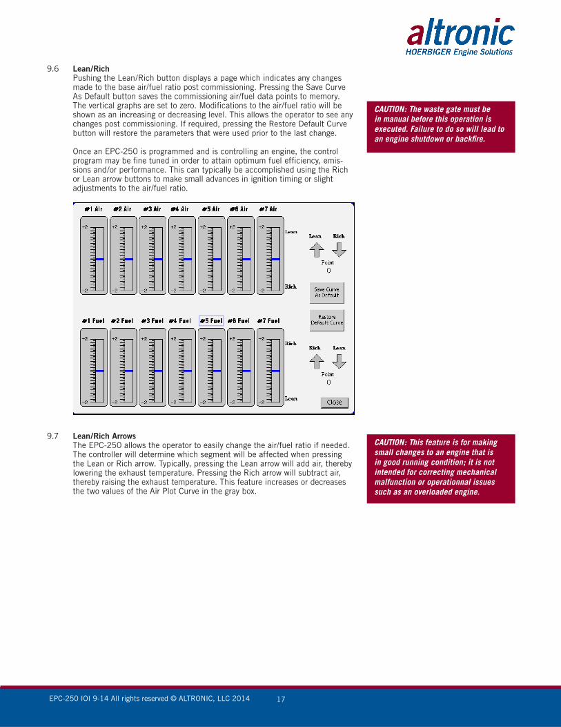
9.6 Lean/Rich Pushing the Lean/Rich button displays a page which indicates any changes
made to the base air/fuel ratio post commissioning. Pressing the Save Curve As Default button saves the commissioning air/fuel data points to memory. The vertical graphs are set to zero. Modifications to the air/fuel ratio will be shown as an increasing or decreasing level. This allows the operator to see any changes post commissioning. If required, pressing the Restore Default Curve button will restore the parameters that were used prior to the last change.
Once an EPC-250 is programmed and is controlling an engine, the control program may be fine tuned in order to attain optimum fuel efficiency, emis-sions and/or performance. This can typically be accomplished using the Rich or Lean arrow buttons to make small advances in ignition timing or slight adjustments to the air/fuel ratio.
9.7 Lean/Rich Arrows The EPC-250 allows the operator to easily change the air/fuel ratio if needed.
The controller will determine which segment will be affected when pressing the Lean or Rich arrow. Typically, pressing the Lean arrow will add air, thereby lowering the exhaust temperature. Pressing the Rich arrow will subtract air, thereby raising the exhaust temperature. This feature increases or decreases the two values of the Air Plot Curve in the gray box.
CAUTION: The waste gate must be in manual before this operation is executed. Failure to do so will lead to an engine shutdown or backfire.
CAUTION: This feature is for making small changes to an engine that is in good running condition; it is not intended for correcting mechanical malfunction or operationnal issues such as an overloaded engine.
EPC-250 IOI 9-14 All rights reserved © ALTRONIC, LLC 2014 18
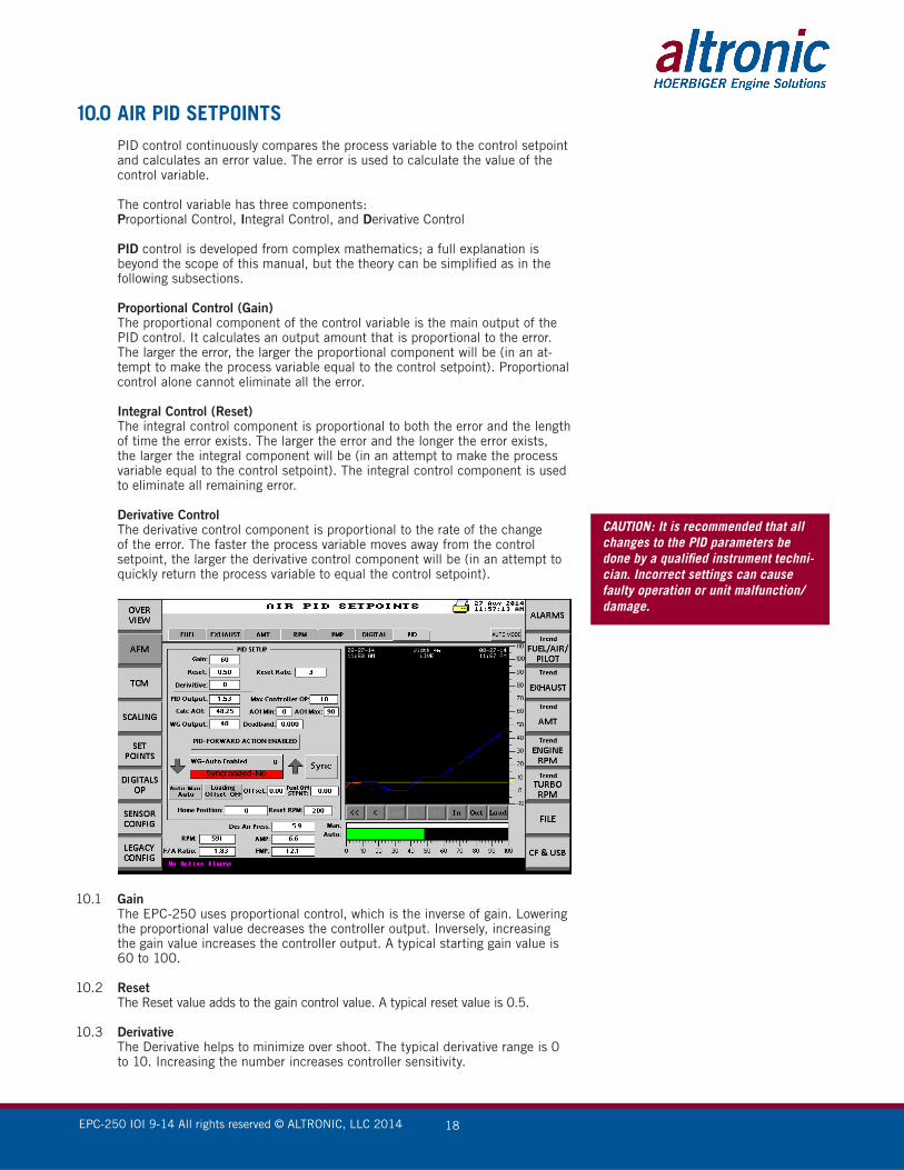
10.0 AIR PID SETPOINTS PID control continuously compares the process variable to the control setpoint
and calculates an error value. The error is used to calculate the value of the control variable.
The control variable has three components: Proportional Control, Integral Control, and Derivative Control
PID control is developed from complex mathematics; a full explanation is beyond the scope of this manual, but the theory can be simplified as in the following subsections.
Proportional Control (Gain) The proportional component of the control variable is the main output of the
PID control. It calculates an output amount that is proportional to the error. The larger the error, the larger the proportional component will be (in an at-tempt to make the process variable equal to the control setpoint). Proportional control alone cannot eliminate all the error.
Integral Control (Reset) The integral control component is proportional to both the error and the length
of time the error exists. The larger the error and the longer the error exists, the larger the integral component will be (in an attempt to make the process variable equal to the control setpoint). The integral control component is used to eliminate all remaining error.
Derivative Control The derivative control component is proportional to the rate of the change
of the error. The faster the process variable moves away from the control setpoint, the larger the derivative control component will be (in an attempt to quickly return the process variable to equal the control setpoint).
10.1 Gain The EPC-250 uses proportional control, which is the inverse of gain. Lowering
the proportional value decreases the controller output. Inversely, increasing the gain value increases the controller output. A typical starting gain value is 60 to 100.
10.2 Reset The Reset value adds to the gain control value. A typical reset value is 0.5.
10.3 Derivative The Derivative helps to minimize over shoot. The typical derivative range is 0
to 10. Increasing the number increases controller sensitivity.
CAUTION: It is recommended that all changes to the PID parameters be done by a qualified instrument techni-cian. Incorrect settings can cause faulty operation or unit malfunction/damage.

EPC-250 IOI 9-14 All rights reserved © ALTRONIC, LLC 2014 19
10.4 Reset Rate Shows how often the PID error is calculated. The value range is from 1 to 10.
10.5 PID Output The PID output is the error calculation. A well-tuned engine with a 0.2PSI dif-
ference between desired and actual air pressure should generate a PID Output of 0.7 maximum. This can be used to adjust the gain setting. Refer to the trend until there is minimal oscillation on the waste gate output.
10.6 Max Controller Output: Max Controller Output limits the maximum PID output. During large engine
swings this function governs the PID output in order to prevent the PID from chasing the engine swings, thereby avoiding an output that is too large to control. The range of this value is from 1 to 99.
10.7 AO1 Min/AO1 Max This is Analog Output 1 on the I/O board. This output is scaled from 0 to 100,
where 0 equals 4mA and 100 equals 20mA. AO1 Min/AO1 Max limits the lower and upper range of the analog output. This is useful if the waste gate sticks when it is below or above a certain value.
10.8 Calc AO1 This is the Calculated Analog Output.
10.9 WG Output This is the actual position of the waste gate.
10.10 Deadband If the desired air manifold pressure is above or below the actual air manifold
pressure by the amount of the deadband value, the controller will respond to this error appropriately. For example, with a deadband of zero, any difference between the actual and the desired air manifold pressure will initiate a control-ler response. With a deadband of 1, the desired air manifold pressure must be greater or less than 1 to initiate a controller output. This can be used with a pulsating air manifold pressure signal.
10.11 PID-Forward Action Enabled This is used to control the mode of the PID signal from forward acting to re-
verse acting. In forward acting mode 0 = 4mA, 100 = 20mA. In reverse acting mode 0 = 20mA and 100 = 4mA.
10.12 WG-Auto Enabled This button toggles the waste gate control from auto to manual. Pushing the
Sync button makes the manual waste gate setpoint equal to the auto waste gate output, but does not automatically switch the output to auto/manual or manual/auto. Once synchronized, the WG-Auto Enabled button turns green. Pressing the Auto/Manual button switches the controller to manual/auto or auto/manual. The Sync button is required to prevent an engine shutdown due to a difference between controller output (4-20mA) in manual mode and controller output (4-20mA) in auto mode. The greater the difference, the more time will be required for the values to synchronize.
10.13 Home position If enabled, the waste gate output will revert to the home position during a fault
or an engine shutdown. Entering a negative value in the RPM setpoint box keeps the controller in automatic mode. Entering a positive value enables the home position feature. During an engine shutdown the waste gate will move to the home position setpoint. When the engine is started the controller will go into automatic mode when the RPM is greater than the RPM setpoint.
10.14 Auto/Manual In Auto the EPC-250 automatically goes into controlling mode when RPM is
above the home position reset value. In Manual mode the reset button on the home page must be pressed in order to enter the auto mode. When input 31 is closed, exceeding the top or bottom limit will reset the EPC-250 if it is in manual mode.
Note: The home position is typically closer to the running position. In the case of a 2400 Superior the home position would be 100. This engine cannot have any air while starting in ramping to idle.
EPC-250 IOI 9-14 All rights reserved © ALTRONIC, LLC 2014 20
10.15 Reset RPM When the engine RPM is greater than the Reset RPM value, the controller will
enter auto mode.
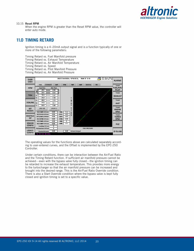
11.0 TIMING RETARD Ignition timing is a 4–20mA output signal and is a function typically of one or
more of the following parameters:
Timing Retard vs. Fuel Manifold pressure Timing Retard vs. Exhaust Temperature Timing Retard vs. Air Manifold Temperature Timing Retard vs. Speed Timing Retard vs. Pilot Manifold Pressure Timing Retard vs. Air Manifold Pressure
The operating values for the functions above are calculated separately accord-
ing to user-entered curves, and the Offset is implemented by the EPC-250 Controller.
Under certain conditions, there can be interaction between the Air/Fuel Ratio and the Timing Retard function. If sufficient air manifold pressure cannot be achieved—even with the bypass valve fully closed—the ignition timing can be retarded to increase the exhaust temperature. This provides more energy to the turbocharger so that the air manifold pressure can be increased and brought into the desired range. This is the Air/Fuel Ratio Override condition. There is also a Start Override condition where the bypass valve is kept fully closed and ignition timing is set to a specific value.
EPC-250 IOI 9-14 All rights reserved © ALTRONIC, LLC 2014 21
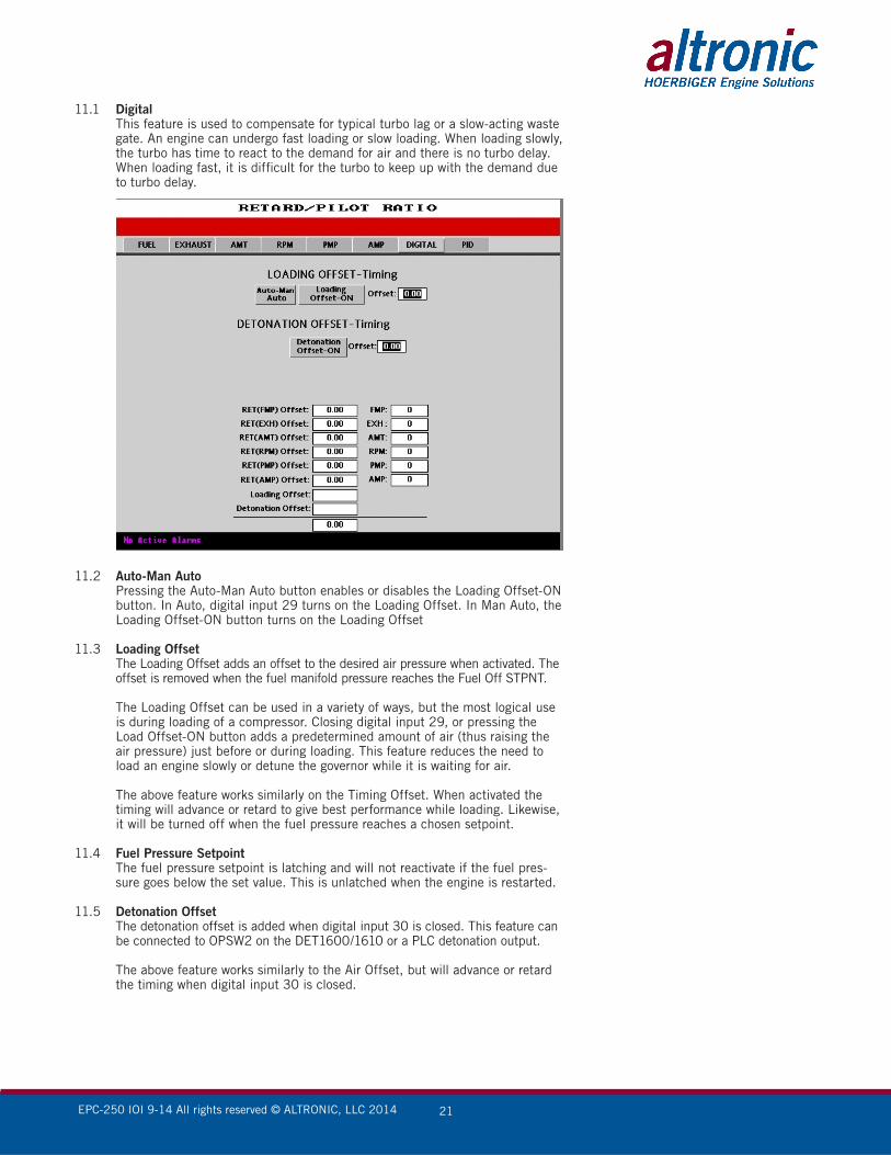
11.1 Digital This feature is used to compensate for typical turbo lag or a slow-acting waste
gate. An engine can undergo fast loading or slow loading. When loading slowly, the turbo has time to react to the demand for air and there is no turbo delay. When loading fast, it is difficult for the turbo to keep up with the demand due to turbo delay.
11.2 Auto-Man Auto Pressing the Auto-Man Auto button enables or disables the Loading Offset-ON
button. In Auto, digital input 29 turns on the Loading Offset. In Man Auto, the Loading Offset-ON button turns on the Loading Offset
11.3 Loading Offset The Loading Offset adds an offset to the desired air pressure when activated. The
offset is removed when the fuel manifold pressure reaches the Fuel Off STPNT.
The Loading Offset can be used in a variety of ways, but the most logical use is during loading of a compressor. Closing digital input 29, or pressing the Load Offset-ON button adds a predetermined amount of air (thus raising the air pressure) just before or during loading. This feature reduces the need to load an engine slowly or detune the governor while it is waiting for air.
The above feature works similarly on the Timing Offset. When activated the timing will advance or retard to give best performance while loading. Likewise, it will be turned off when the fuel pressure reaches a chosen setpoint.
11.4 Fuel Pressure Setpoint The fuel pressure setpoint is latching and will not reactivate if the fuel pres-
sure goes below the set value. This is unlatched when the engine is restarted.
11.5 Detonation Offset The detonation offset is added when digital input 30 is closed. This feature can
be connected to OPSW2 on the DET1600/1610 or a PLC detonation output.
The above feature works similarly to the Air Offset, but will advance or retard the timing when digital input 30 is closed.
EPC-250 IOI 9-14 All rights reserved © ALTRONIC, LLC 2014 22
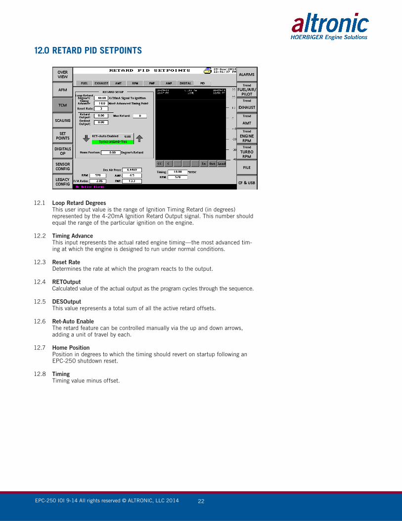
12.0 RETARD PID SETPOINTS
12.1 Loop Retard Degrees This user input value is the range of Ignition Timing Retard (in degrees)
represented by the 4-20mA Ignition Retard Output signal. This number should equal the range of the particular ignition on the engine.
12.2 Timing Advance This input represents the actual rated engine timing—the most advanced tim-
ing at which the engine is designed to run under normal conditions.
12.3 Reset Rate Determines the rate at which the program reacts to the output.
12.4 RETOutput Calculated value of the actual output as the program cycles through the sequence.
12.5 DESOutput This value represents a total sum of all the active retard offsets.
12.6 Ret-Auto Enable The retard feature can be controlled manually via the up and down arrows,
adding a unit of travel by each.
12.7 Home Position Position in degrees to which the timing should revert on startup following an
EPC-250 shutdown reset.
12.8 Timing Timing value minus offset.
EPC-250 IOI 9-14 All rights reserved © ALTRONIC, LLC 2014 23
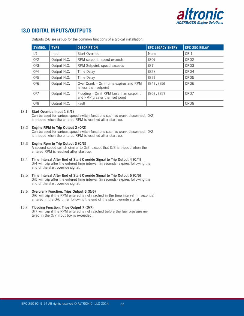
13.0 DIGITAL INPUTS/OUTPUTS Outputs 2-8 are set-up for the common functions of a typical installation.
SYMBOL TYPE DESCRIPTION EPC LEGACY ENTRY EPC-250 RELAY
I/1 Input Start Override None CRI1
O/2 Output N.C. RPM setpoint, speed exceeds (80) CRO2
O/3 Output N.O. RPM Setpoint, speed exceeds (81) CRO3
O/4 Output N.C. Time Delay (82) CRO4
O/5 Output N.O. Time Delay (83) CRO5
O/6 Output N.C. Over Crank – On if time expires and RPM is less than setpoint
(84) , (85) CRO6
O/7 Output N.C. Flooding – On if RPM Less than setpoint and FMP greater than set point
(86) , (87) CRO7
O/8 Output N.C. Fault CRO8
13.1 Start Override Input 1 (I/1) Can be used for various speed switch functions such as crank disconnect. 0/2
is tripped when the entered RPM is reached after start-up.
13.2 Engine RPM to Trip Output 2 (0/2) Can be used for various speed switch functions such as crank disconnect. 0/2
is tripped when the entered RPM is reached after start-up.
13.3 Engine Rpm to Trip Output 3 (0/3) A second speed switch similar to O/2, except that 0/3 is tripped when the
entered RPM is reached after start-up.
13.4 Time Interval After End of Start Override Signal to Trip Output 4 (0/4) 0/4 will trip after the entered time interval (in seconds) expires following the
end of the start override signal.
13.5 Time Interval After End of Start Override Signal to Trip Output 5 (0/5) 0/5 will trip after the entered time interval (in seconds) expires following the
end of the start override signal.
13.6 Overcrank Function, Trips Output 6 (0/6) 0/6 will trip if the RPM entered is not reached in the time interval (in seconds)
entered in the O/6 timer following the end of the start override signal.
13.7 Flooding Function, Trips Output 7 (0/7) 0/7 will trip if the RPM entered is not reached before the fuel pressure en-
tered in the O/7 input box is exceeded.
EPC-250 IOI 9-14 All rights reserved © ALTRONIC, LLC 2014 24
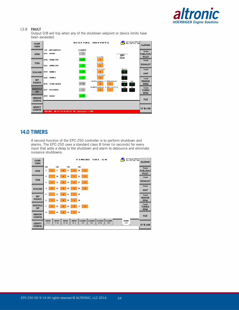
13.8 FAULT Output 0/8 will trip when any of the shutdown setpoint or device limits have
been exceeded.
14.0 TIMERS A second function of the EPC-250 controller is to perform shutdown and
alarms. The EPC-250 uses a standard class B timer (in seconds) for every input that adds a delay to the shutdown and alarm to debounce and eliminate nuisance shutdowns.

EPC-250 IOI 9-14 All rights reserved © ALTRONIC, LLC 2014 25
15.0 Configuration
15.1 SAVE TO CF CONFIG The EPC-250 provides the capability of saving the configuration of each chan-
nel to the SD Memory card.
15.2 LOAD FROM CF CONFIG The saved configuration of section 15.1 can be recalled and loaded to a new
application or back to the original EPC-250 in case of data loss.
15.3 CREATE CONFIG REPORT A report of the configuration saved in the SD Memory card can be generated
by using this function
15.4 OPEN CONFIG FILE VIEWER Allows the user to view the configured file in a readable format (.TXT).
15.5 PRINT EPC CONFIG A hard copy can be printed if the EPC-250 is connected to a printer.
15.6 CREATE DATA REPORT A report of the working data (press, temps, air/fuel ratio…etc)
EPC-250 IOI 9-14 All rights reserved © ALTRONIC, LLC 2014 26
15.7 PRINT EPC DATA A hard copy can be printed if the EPC-250 is connected to a printer.
15.8 OPEN DATA FILE VIEWER Allows the user to view the data in a readable format (.TXT).
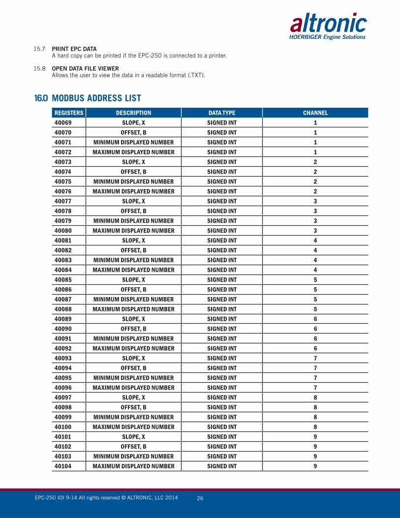
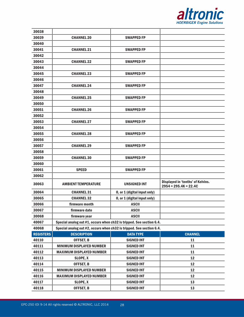
16.0 MODBUS ADDRESS LIST
REGISTERS DESCRIPTION DATA TYPE CHANNEL40069 SLOPE, X SIGNED INT 140070 OFFSET, B SIGNED INT 140071 MINIMUM DISPLAYED NUMBER SIGNED INT 140072 MAXIMUM DISPLAYED NUMBER SIGNED INT 140073 SLOPE, X SIGNED INT 240074 OFFSET, B SIGNED INT 240075 MINIMUM DISPLAYED NUMBER SIGNED INT 240076 MAXIMUM DISPLAYED NUMBER SIGNED INT 240077 SLOPE, X SIGNED INT 340078 OFFSET, B SIGNED INT 340079 MINIMUM DISPLAYED NUMBER SIGNED INT 340080 MAXIMUM DISPLAYED NUMBER SIGNED INT 340081 SLOPE, X SIGNED INT 440082 OFFSET, B SIGNED INT 440083 MINIMUM DISPLAYED NUMBER SIGNED INT 440084 MAXIMUM DISPLAYED NUMBER SIGNED INT 440085 SLOPE, X SIGNED INT 540086 OFFSET, B SIGNED INT 540087 MINIMUM DISPLAYED NUMBER SIGNED INT 540088 MAXIMUM DISPLAYED NUMBER SIGNED INT 540089 SLOPE, X SIGNED INT 640090 OFFSET, B SIGNED INT 640091 MINIMUM DISPLAYED NUMBER SIGNED INT 640092 MAXIMUM DISPLAYED NUMBER SIGNED INT 640093 SLOPE, X SIGNED INT 740094 OFFSET, B SIGNED INT 740095 MINIMUM DISPLAYED NUMBER SIGNED INT 740096 MAXIMUM DISPLAYED NUMBER SIGNED INT 740097 SLOPE, X SIGNED INT 840098 OFFSET, B SIGNED INT 840099 MINIMUM DISPLAYED NUMBER SIGNED INT 840100 MAXIMUM DISPLAYED NUMBER SIGNED INT 840101 SLOPE, X SIGNED INT 940102 OFFSET, B SIGNED INT 940103 MINIMUM DISPLAYED NUMBER SIGNED INT 940104 MAXIMUM DISPLAYED NUMBER SIGNED INT 9

EPC-250 IOI 9-14 All rights reserved © ALTRONIC, LLC 2014 27
REGISTERS DESCRIPTION DATA TYPE CHANNEL40105 SLOPE, X SIGNED INT 1040106 OFFSET, B SIGNED INT 1040107 MINIMUM DISPLAYED NUMBER SIGNED INT 1040108 MAXIMUM DISPLAYED NUMBER SIGNED INT 1040109 SLOPE, X SIGNED INT 11
REGISTERS DESCRIPTION DATA TYPE30001 CHANNEL 1 SWAPPED FP3000230003 CHANNEL 2 SWAPPED FP3000430005 CHANNEL 3 SWAPPED FP3000630007 CHANNEL 4 SWAPPED FP3000830009 CHANNEL 5 SWAPPED FP3001030011 CHANNEL 6 SWAPPED FP3001230013 CHANNEL 7 SWAPPED FP3001430015 CHANNEL 8 SWAPPED FP3001630017 CHANNEL 9 SWAPPED FP3001830019 CHANNEL 10 SWAPPED FP3002030021 CHANNEL 11 SWAPPED FP3002230023 CHANNEL 12 SWAPPED FP3002430025 CHANNEL 13 SWAPPED FP3002630027 CHANNEL 14 SWAPPED FP3002830029 CHANNEL 15 SWAPPED FP3003030031 CHANNEL 16 SWAPPED FP3003230033 CHANNEL 17 SWAPPED FP3003430035 CHANNEL 18 SWAPPED FP3003630037 CHANNEL 19 SWAPPED FP
EPC-250 IOI 9-14 All rights reserved © ALTRONIC, LLC 2014 28
REGISTERS DESCRIPTION DATA TYPE CHANNEL40110 OFFSET, B SIGNED INT 1140111 MINIMUM DISPLAYED NUMBER SIGNED INT 1140112 MAXIMUM DISPLAYED NUMBER SIGNED INT 1140113 SLOPE, X SIGNED INT 1240114 OFFSET, B SIGNED INT 1240115 MINIMUM DISPLAYED NUMBER SIGNED INT 1240116 MAXIMUM DISPLAYED NUMBER SIGNED INT 1240117 SLOPE, X SIGNED INT 1340118 OFFSET, B SIGNED INT 13
3003830039 CHANNEL 20 SWAPPED FP3004030041 CHANNEL 21 SWAPPED FP3004230043 CHANNEL 22 SWAPPED FP3004430045 CHANNEL 23 SWAPPED FP3004630047 CHANNEL 24 SWAPPED FP3004830049 CHANNEL 25 SWAPPED FP3005030051 CHANNEL 26 SWAPPED FP3005230053 CHANNEL 27 SWAPPED FP3005430055 CHANNEL 28 SWAPPED FP3005630057 CHANNEL 29 SWAPPED FP3005830059 CHANNEL 30 SWAPPED FP3006030061 SPEED SWAPPED FP30062
30063 AMBIENT TEMPERATURE UNSIGNED INT Displayed in ‘tenths’ of Kelvins.2954 = 295.4K = 22.4C
30064 CHANNEL 31 0, or 1 (digital input only)30065 CHANNEL 32 0, or 1 (digital input only)30066 firmware month ASCII30067 firmware date ASCII30068 firmware year ASCII40067 Special analog out #1, occurs when ch32 is tripped. See section 6.4.40068 Special analog out #2, occurs when ch32 is tripped. See section 6.4.
EPC-250 IOI 9-14 All rights reserved © ALTRONIC, LLC 2014 29
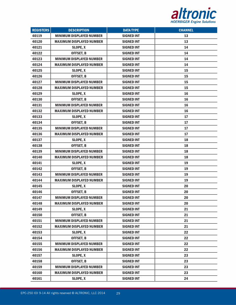
REGISTERS DESCRIPTION DATA TYPE CHANNEL40119 MINIMUM DISPLAYED NUMBER SIGNED INT 1340120 MAXIMUM DISPLAYED NUMBER SIGNED INT 1340121 SLOPE, X SIGNED INT 1440122 OFFSET, B SIGNED INT 1440123 MINIMUM DISPLAYED NUMBER SIGNED INT 1440124 MAXIMUM DISPLAYED NUMBER SIGNED INT 1440125 SLOPE, X SIGNED INT 1540126 OFFSET, B SIGNED INT 1540127 MINIMUM DISPLAYED NUMBER SIGNED INT 1540128 MAXIMUM DISPLAYED NUMBER SIGNED INT 1540129 SLOPE, X SIGNED INT 1640130 OFFSET, B SIGNED INT 1640131 MINIMUM DISPLAYED NUMBER SIGNED INT 1640132 MAXIMUM DISPLAYED NUMBER SIGNED INT 1640133 SLOPE, X SIGNED INT 1740134 OFFSET, B SIGNED INT 1740135 MINIMUM DISPLAYED NUMBER SIGNED INT 1740136 MAXIMUM DISPLAYED NUMBER SIGNED INT 1740137 SLOPE, X SIGNED INT 1840138 OFFSET, B SIGNED INT 1840139 MINIMUM DISPLAYED NUMBER SIGNED INT 1840140 MAXIMUM DISPLAYED NUMBER SIGNED INT 1840141 SLOPE, X SIGNED INT 1940142 OFFSET, B SIGNED INT 1940143 MINIMUM DISPLAYED NUMBER SIGNED INT 1940144 MAXIMUM DISPLAYED NUMBER SIGNED INT 1940145 SLOPE, X SIGNED INT 2040146 OFFSET, B SIGNED INT 2040147 MINIMUM DISPLAYED NUMBER SIGNED INT 2040148 MAXIMUM DISPLAYED NUMBER SIGNED INT 2040149 SLOPE, X SIGNED INT 2140150 OFFSET, B SIGNED INT 2140151 MINIMUM DISPLAYED NUMBER SIGNED INT 2140152 MAXIMUM DISPLAYED NUMBER SIGNED INT 2140153 SLOPE, X SIGNED INT 2240154 OFFSET, B SIGNED INT 2240155 MINIMUM DISPLAYED NUMBER SIGNED INT 2240156 MAXIMUM DISPLAYED NUMBER SIGNED INT 2240157 SLOPE, X SIGNED INT 2340158 OFFSET, B SIGNED INT 2340159 MINIMUM DISPLAYED NUMBER SIGNED INT 2340160 MAXIMUM DISPLAYED NUMBER SIGNED INT 2340161 SLOPE, X SIGNED INT 24
EPC-250 IOI 9-14 All rights reserved © ALTRONIC, LLC 2014 30
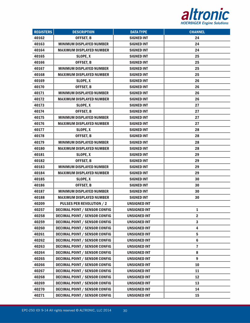
REGISTERS DESCRIPTION DATA TYPE CHANNEL40162 OFFSET, B SIGNED INT 2440163 MINIMUM DISPLAYED NUMBER SIGNED INT 2440164 MAXIMUM DISPLAYED NUMBER SIGNED INT 2440165 SLOPE, X SIGNED INT 2540166 OFFSET, B SIGNED INT 2540167 MINIMUM DISPLAYED NUMBER SIGNED INT 2540168 MAXIMUM DISPLAYED NUMBER SIGNED INT 2540169 SLOPE, X SIGNED INT 2640170 OFFSET, B SIGNED INT 2640171 MINIMUM DISPLAYED NUMBER SIGNED INT 2640172 MAXIMUM DISPLAYED NUMBER SIGNED INT 2640173 SLOPE, X SIGNED INT 2740174 OFFSET, B SIGNED INT 2740175 MINIMUM DISPLAYED NUMBER SIGNED INT 2740176 MAXIMUM DISPLAYED NUMBER SIGNED INT 2740177 SLOPE, X SIGNED INT 2840178 OFFSET, B SIGNED INT 2840179 MINIMUM DISPLAYED NUMBER SIGNED INT 2840180 MAXIMUM DISPLAYED NUMBER SIGNED INT 2840181 SLOPE, X SIGNED INT 2940182 OFFSET, B SIGNED INT 2940183 MINIMUM DISPLAYED NUMBER SIGNED INT 2940184 MAXIMUM DISPLAYED NUMBER SIGNED INT 2940185 SLOPE, X SIGNED INT 3040186 OFFSET, B SIGNED INT 3040187 MINIMUM DISPLAYED NUMBER SIGNED INT 3040188 MAXIMUM DISPLAYED NUMBER SIGNED INT 3040209 PULSES PER REVOLUTION / 2 UNSIGNED INT40257 DECIMAL POINT / SENSOR CONFIG UNSIGNED INT 140258 DECIMAL POINT / SENSOR CONFIG UNSIGNED INT 240259 DECIMAL POINT / SENSOR CONFIG UNSIGNED INT 340260 DECIMAL POINT / SENSOR CONFIG UNSIGNED INT 440261 DECIMAL POINT / SENSOR CONFIG UNSIGNED INT 540262 DECIMAL POINT / SENSOR CONFIG UNSIGNED INT 640263 DECIMAL POINT / SENSOR CONFIG UNSIGNED INT 740264 DECIMAL POINT / SENSOR CONFIG UNSIGNED INT 840265 DECIMAL POINT / SENSOR CONFIG UNSIGNED INT 940266 DECIMAL POINT / SENSOR CONFIG UNSIGNED INT 1040267 DECIMAL POINT / SENSOR CONFIG UNSIGNED INT 1140268 DECIMAL POINT / SENSOR CONFIG UNSIGNED INT 1240269 DECIMAL POINT / SENSOR CONFIG UNSIGNED INT 1340270 DECIMAL POINT / SENSOR CONFIG UNSIGNED INT 1440271 DECIMAL POINT / SENSOR CONFIG UNSIGNED INT 15
EPC-250 IOI 9-14 All rights reserved © ALTRONIC, LLC 2014 31
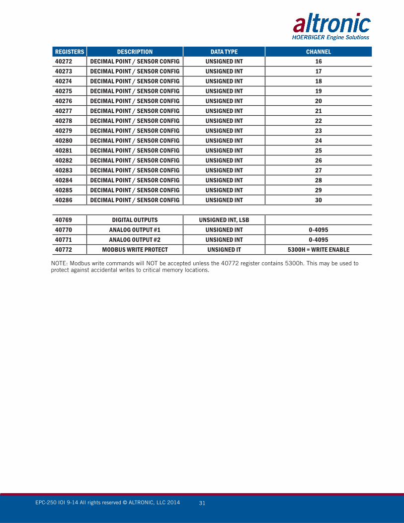
REGISTERS DESCRIPTION DATA TYPE CHANNEL40272 DECIMAL POINT / SENSOR CONFIG UNSIGNED INT 1640273 DECIMAL POINT / SENSOR CONFIG UNSIGNED INT 1740274 DECIMAL POINT / SENSOR CONFIG UNSIGNED INT 1840275 DECIMAL POINT / SENSOR CONFIG UNSIGNED INT 1940276 DECIMAL POINT / SENSOR CONFIG UNSIGNED INT 2040277 DECIMAL POINT / SENSOR CONFIG UNSIGNED INT 2140278 DECIMAL POINT / SENSOR CONFIG UNSIGNED INT 2240279 DECIMAL POINT / SENSOR CONFIG UNSIGNED INT 2340280 DECIMAL POINT / SENSOR CONFIG UNSIGNED INT 2440281 DECIMAL POINT / SENSOR CONFIG UNSIGNED INT 2540282 DECIMAL POINT / SENSOR CONFIG UNSIGNED INT 2640283 DECIMAL POINT / SENSOR CONFIG UNSIGNED INT 2740284 DECIMAL POINT / SENSOR CONFIG UNSIGNED INT 2840285 DECIMAL POINT / SENSOR CONFIG UNSIGNED INT 2940286 DECIMAL POINT / SENSOR CONFIG UNSIGNED INT 30
40769 DIGITAL OUTPUTS UNSIGNED INT, LSB40770 ANALOG OUTPUT #1 UNSIGNED INT 0-409540771 ANALOG OUTPUT #2 UNSIGNED INT 0-409540772 MODBUS WRITE PROTECT UNSIGNED IT 5300H = WRITE ENABLE
NOTE: Modbus write commands will NOT be accepted unless the 40772 register contains 5300h. This may be used to protect against accidental writes to critical memory locations.

EPC-250 IOI 9-14 All rights reserved © ALTRONIC, LLC 2014 32
DRAWINGS SECTION
FIGURE 1 — MODBUS TERMINAL BOARD
FIGURE 2 — WIRING DIAGRAM, SENSOR AND TRANSDUCER INPUTS/POWER
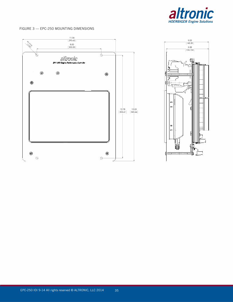
FIGURE 3 — EPC-250 MOUNTING DIMENSIONS
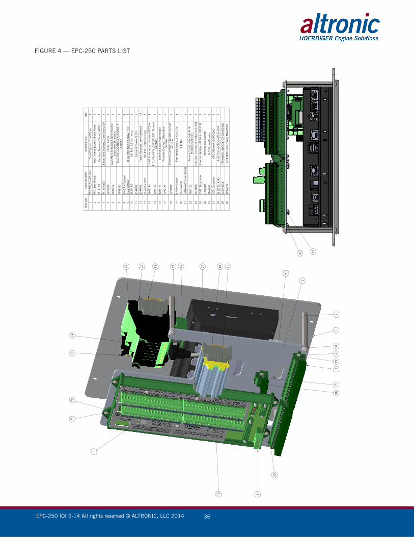
FIGURE 4— EPC-250 PARTS LIST
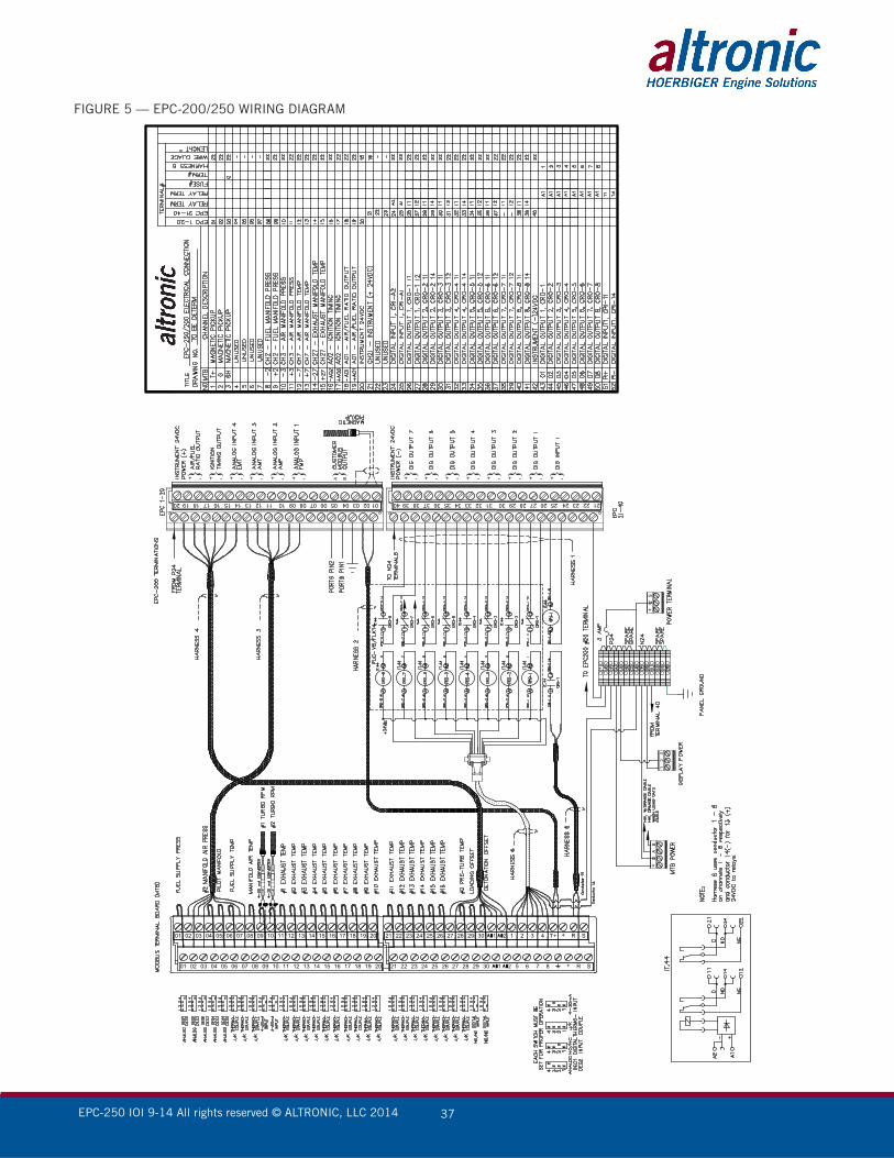
FIGURE 5 — EPC-200/250 WIRING DIAGRAM

EPC-250 IOI 9-14 All rights reserved © ALTRONIC, LLC 2014 33
FIGURE 1 — MODBUS TERMINAL BOARD
EPC-250 IOI 9-14 All rights reserved © ALTRONIC, LLC 2014 34
FIGURE 2 — WIRING DIAGRAM, SENSOR AND TRANSDUCER INPUTS/POWER
EPC-250 IOI 9-14 All rights reserved © ALTRONIC, LLC 2014 35
FIGURE 3 — EPC-250 MOUNTING DIMENSIONS
11.56293.62
13.53343.66
12.78324.61
5.53140.50
5.28134.154
8.00203.20
EPC-250 IOI 9-14 All rights reserved © ALTRONIC, LLC 2014 36
FIGURE 4 — EPC-250 PARTS LIST
3
921
1614
26 1325 22 15 27 10 11
41
28
86
1917
718
2
512
20
20 21
ITEM
NO
.PA
RT N
UMBE
RD
ESC
RIPT
ION
QTY
.1
EPC
250_
Fron
tPla
te1
Pane
l Exp
ress
, Fro
nt P
late
1
2EP
C_B
ackP
late
1Fr
ont P
anel
Exp
ress
, Bac
k Pl
ate
1
369
1217
-1M
odbu
s Ter
mia
nl B
oard
(MTB
)1
491
115A
853
3 in
ch 1
8-8
Stai
nles
s Ste
el S
tand
Off
4
517
9226
5PL
UG, 4
-PO
S1
617
8871
6M
VST
BU 2
,5/2
0-G
B-5,
08 2
0 Po
sitio
n ba
se st
rip (
Phoe
nix)
2
717
8835
0Ba
se S
trip-
MV
STBU
2,5
/3-G
FB5,
3
posit
ion
1
84-
40 P
H Sc
rew
69
8-32
Scr
ew8-
32 P
an h
ead
Scr
ew 1
/4"
410
6152
43-2
D
in R
ail,
2.5
inch
long
1
1130
4409
2G
roun
d T
erm
inal
, Din
212
3044
076
Feed
-Thr
ough
Ter
min
al B
lock
13
1361
5243
-2 A
lt#D
in R
ail,
5.50
inch
long
1
1456
0315
4So
lid S
tate
rela
y m
odul
e-24
DC
/3A
9
1523
0410
2PL
C_V
8_FL
K14_
OUT
_SEL
ECT,
Pho
enix
cont
act
1
1630
0417
1Te
rmin
al B
lock
Fus
e Ho
lder
1
1717
9219
7Ph
oeni
x C
onta
ct, 2
0 po
sitio
n Fe
mal
e 2
1817
9202
9Ph
oeni
x C
onta
ct 3
pos
ition
pow
er
term
inal
1
194-
40 P
H Sc
rew
Pan
Head
Scr
ew, 4
-40
x 7/
16"
6
2011
CN
M51
84-
40 N
ut5
21M
SHXN
UT 0
.164
-32-
S-N
4
2229
0012
2Ro
und
Cab
le, V
ip-c
ab-fl
k14,
Ph
oeni
x C
onta
ct1
23SA
N4G
BSa
n D
isk, C
ompa
ct F
lash
Car
d, 2
GB
1
2402
0113
9_ju
mpe
rIn
serti
on B
ridge
- EB
10-
6 - 0
2011
391
25E_
NS3
5NTe
rmin
al E
nd C
lam
p4
2629
6684
1PL
C P
late
s/D
ivid
er2
27G
09_G
raph
iteEP
C-2
50 H
MI,
G09
C00
001
2816
5672
5_RJ
45RJ
45 C
onne
ctio
n M
TB to
HM
I1
2914
92-J
G4
TERM
INA
L BL
OC
K G
ROUN
DIN
G30
2976
077
MTB
SID
E M
OUT
ING
BRA
CKE
T
EPC-250 IOI 9-14 All rights reserved © ALTRONIC, LLC 2014 37
FIGURE 5 — EPC-200/250 WIRING DIAGRAM
1110 12 13 14 15 16 17 18 19 20090807060504030201
1110 12 13 14 15 16 17 18 19 20090807060504030201 30 1 2 3 4 T+ + R S292827262524232221
30 5 6 7 8 + R S292827262524232221
}+ -}+ -}+ -}+ -}+ -}+ -}+ - }+ -}+ -}+ -}+ -}+ -}+ -}+ -
+
AB
+
S
32
1
31 30323334353637383940 29 28 27 26 25 24 23 22 2111 10121314151617181920 09 08 07 06 05 04 03 02 01
} BA