Embed Size (px)
Citation preview

Installation and Operating Guide Document No. 1788-04
ValuLine Softwall Modular Cleanroom © Copyright 2018 Terra Universal Inc. All rights reserved. • Revised February 2018
Terra Universal, Inc. • TerraUniversal.com • 800 S. Raymond Ave. • Fullerton, CA 92831 • TEL: (714) 578-6000 • FAX: (714) 578-6020

Installation and Operating Guide
ValuLine Softwall Modular Cleanroom © Copyright 2018 Terra Universal Inc. All rights reserved. • Revised February 2018 • Document No. 1788-04
Terra Universal, Inc. • TerraUniversal.com • 800 S. Raymond Ave. • Fullerton, CA 92831 • TEL: (714) 578-6000 • FAX: (714) 578-6020 2
Table of Contents
1.0 Introduction...................................................................................................................................................................... 3
2.0 Description ....................................................................................................................................................................... 4
2.1 Standard Component List ................................................................................................................................................ 4
3.0 Installation ........................................................................................................................................................................ 5
3.1 Recommended Tools........................................................................................................................................................................5
3.2 Site Preparation ................................................................................................................................................................................5
3.3 Installing the Support Frame ............................................................................................................................................................6
3.4 Installing the Ceiling Grid .................................................................................................................................................................7
3.5 Installing Ceiling Components .........................................................................................................................................................9
3.6 Installing the Power Supply Unit (PSU) ...........................................................................................................................................9
3.7 Installing the Wall Panels and Strip Shields.................................................................................................................................. 10
3.8 Initial Start-Up .................................................................................................................................................................................. 11
4.0 Operation and Maintenance ........................................................................................................................................ 11
4.1 Basic Operation ............................................................................................................................................................................... 11
4.2 Cleaning and Sterilization ............................................................................................................................................................... 11
4.3 Filter Replacement Guidelines ....................................................................................................................................................... 12
4.4 Removing the Fan/Filter Unit ......................................................................................................................................................... 12
4.5 Replacing the HEPA Filter.............................................................................................................................................................. 13
5.0 Specifications ................................................................................................................................................................ 14
5.1 Fan Filter Units ................................................................................................................................................................................ 14
5.2 UL-Listed Components ................................................................................................................................................................... 14
6.0 Warranty ......................................................................................................................................................................... 15
7.0 Spare Parts and Accessories ...................................................................................................................................... 16
8.0 Hardware Reference Table .......................................................................................................................................... 17

Installation and Operating Guide
ValuLine Softwall Modular Cleanroom © Copyright 2018 Terra Universal Inc. All rights reserved. • Revised February 2018 • Document No. 1788-04
Terra Universal, Inc. • TerraUniversal.com • 800 S. Raymond Ave. • Fullerton, CA 92831 • TEL: (714) 578-6000 • FAX: (714) 578-6020 3
1.0 Introduction
This manual provides information on installing and operating your Terra Universal Softwall Modular Cleanroom.
IMPORTANT SAFETY NOTICE
Terra Universal Cleanrooms are not designed to support more weight than the blower modules and lighting fixtures originally installed. In particular, the ceiling grid beams are not load-bearing and will not support personnel or other additional loads. Placing added weight on the ceiling grid may result in serious damage to the cleanroom and its occupants.
Safety notices supplied by Terra Universal must be affixed at appropriate places on each side of the cleanroom grid.
Although this installation/operation manual accurately describes the general design of these cleanrooms, individual orders may vary in dimensions and other design specifics. Refer to any attached drawings and/or parts lists for information specific to your order.
Proprietary Notice
This manual pertains to proprietary devices manufactured by Terra Universal, Inc. Neither this document nor any portion of it may be reproduced in any way without prior written permission from Terra Universal.
Terra Universal makes no warranties applying to information contained in this manual or its suitability for any implied or inferred purpose. Terra Universal shall not be held liable for any errors this manual contains or for any damages that result from its use.
Safety Notice A thorough familiarity with all operating guidelines is essential to safe operation of the product. Failure to observe safety precautions could result in poor performance, damage to the system or other property, or serious bodily injury or death. The following symbols are intended to call your attention to two levels of hazard involved in operation:
Cautions are used when failure to observe instructions
could result in significant damage to equipment.
CAUTION
Warnings are used when failure to observe instructions or precautions could result in injury or death.
WARNING
The information presented here is subject to change without notice.
Installation and Operating Guide
ValuLine Softwall Modular Cleanroom © Copyright 2018 Terra Universal Inc. All rights reserved. • Revised February 2018 • Document No. 1788-04
Terra Universal, Inc. • TerraUniversal.com • 800 S. Raymond Ave. • Fullerton, CA 92831 • TEL: (714) 578-6000 • FAX: (714) 578-6020 4
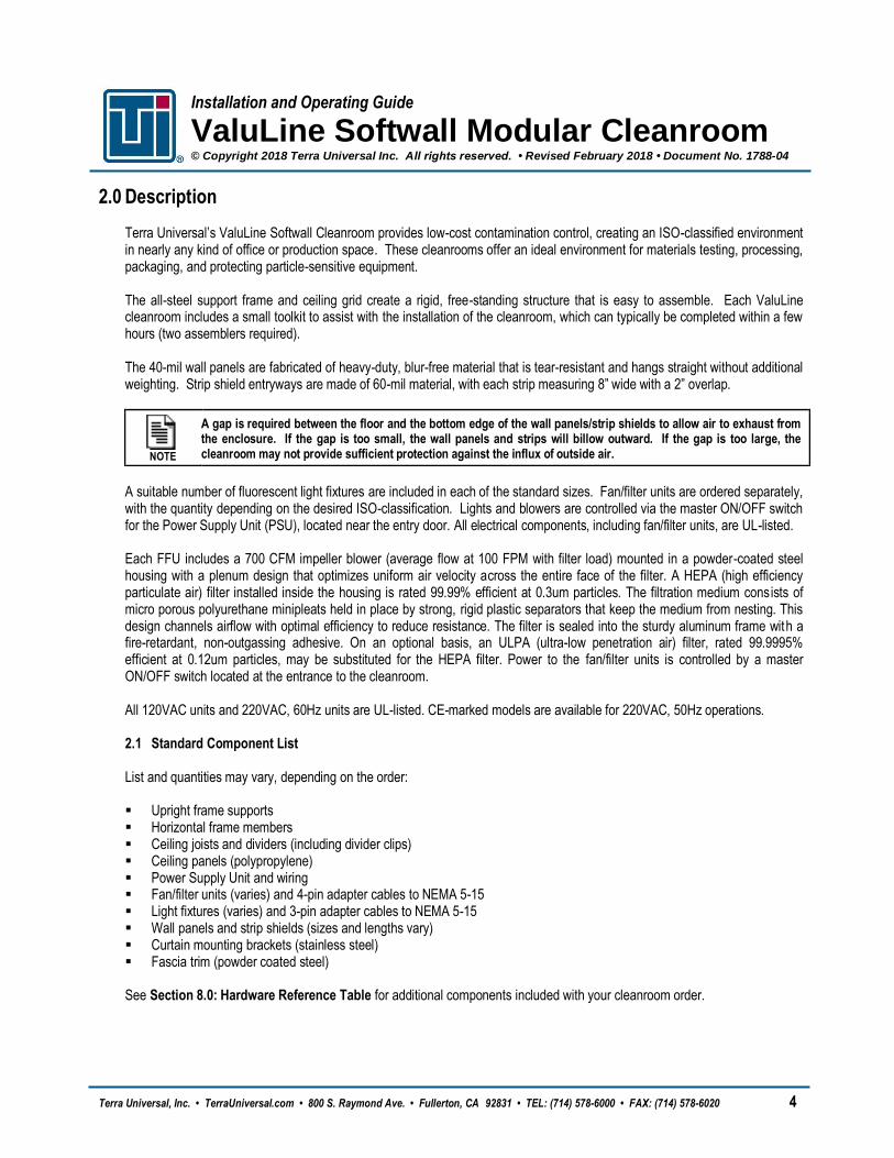
2.0 Description Terra Universal’s ValuLine Softwall Cleanroom provides low-cost contamination control, creating an ISO-classified environment in nearly any kind of office or production space. These cleanrooms offer an ideal environment for materials testing, processing, packaging, and protecting particle-sensitive equipment. The all-steel support frame and ceiling grid create a rigid, free-standing structure that is easy to assemble. Each ValuLine cleanroom includes a small toolkit to assist with the installation of the cleanroom, which can typically be completed within a few hours (two assemblers required). The 40-mil wall panels are fabricated of heavy-duty, blur-free material that is tear-resistant and hangs straight without additional weighting. Strip shield entryways are made of 60-mil material, with each strip measuring 8” wide with a 2” overlap.
NOTE
A gap is required between the floor and the bottom edge of the wall panels/strip shields to allow air to exhaust from the enclosure. If the gap is too small, the wall panels and strips will billow outward. If the gap is too large, the cleanroom may not provide sufficient protection against the influx of outside air.
A suitable number of fluorescent light fixtures are included in each of the standard sizes. Fan/filter units are ordered separately, with the quantity depending on the desired ISO-classification. Lights and blowers are controlled via the master ON/OFF switch for the Power Supply Unit (PSU), located near the entry door. All electrical components, including fan/filter units, are UL-listed. Each FFU includes a 700 CFM impeller blower (average flow at 100 FPM with filter load) mounted in a powder-coated steel housing with a plenum design that optimizes uniform air velocity across the entire face of the filter. A HEPA (high efficiency particulate air) filter installed inside the housing is rated 99.99% efficient at 0.3um particles. The filtration medium consists of micro porous polyurethane minipleats held in place by strong, rigid plastic separators that keep the medium from nesting. This design channels airflow with optimal efficiency to reduce resistance. The filter is sealed into the sturdy aluminum frame with a fire-retardant, non-outgassing adhesive. On an optional basis, an ULPA (ultra-low penetration air) filter, rated 99.9995% efficient at 0.12um particles, may be substituted for the HEPA filter. Power to the fan/filter units is controlled by a master ON/OFF switch located at the entrance to the cleanroom. All 120VAC units and 220VAC, 60Hz units are UL-listed. CE-marked models are available for 220VAC, 50Hz operations. 2.1 Standard Component List List and quantities may vary, depending on the order: Upright frame supports Horizontal frame members Ceiling joists and dividers (including divider clips) Ceiling panels (polypropylene) Power Supply Unit and wiring Fan/filter units (varies) and 4-pin adapter cables to NEMA 5-15 Light fixtures (varies) and 3-pin adapter cables to NEMA 5-15 Wall panels and strip shields (sizes and lengths vary) Curtain mounting brackets (stainless steel) Fascia trim (powder coated steel) See Section 8.0: Hardware Reference Table for additional components included with your cleanroom order.

Installation and Operating Guide
ValuLine Softwall Modular Cleanroom © Copyright 2018 Terra Universal Inc. All rights reserved. • Revised February 2018 • Document No. 1788-04
Terra Universal, Inc. • TerraUniversal.com • 800 S. Raymond Ave. • Fullerton, CA 92831 • TEL: (714) 578-6000 • FAX: (714) 578-6020 5
3.0 Installation
Handling cleanroom shipping crates, which generally measure over 300 inches long and weigh well over 1,000 pounds, requires at least one forklift or pallet jack. If crates must be moved through narrow aisles or entrances, two forklifts or pallet jacks are recommended, one to support each end.
WARNING
Unloading crates from the truck is much easier if you have a truck-high loading dock. Without such a dock, you will need at least one forklift and a support to brace one end while the forklift is positioned beneath the center of each crate. Several men are required to unload individual components from crates. Before proceeding, carefully lay out all system components in staging area adjacent to the installation site. All system crates include packing lists; uncrate and inspect each component. Any damage should be reported immediately to the shipping company (see Warranty). Please notify Terra immediately in the event of missing parts. 3.1 Recommended Tools
Forklift or Pallet Jack – Handling cleanroom shipping crates, which generally measure over 300” long and weigh well over 1,000 pounds, requires at least one (1) forklift or pallet jack. If crates must be moved through narrow aisles or entrances, two (2) forklifts or pallet jacks are recommended, one (1) to support each end
Truck-High Loading Dock – Unloading crates from the truck is much easier if you have a truck-high loading dock. Without such a dock, you will need at least one (1) forklift and a support to brace one end while the forklift is positioned beneath the center of each crate.
Electric Screwdriver with a 8”-12” Shaft Extension (to drive screws in narrow gaps between parts)
Rubber Mallet
Scissors
Measuring Tape (to make sure everything is square)
Level
6’ Ladder
Six (6) to ten (10) Locking C-Clamps (to hold beams in place as fasteners are inserted)
Step Stools
Tables (two or three of the 6’ banquet-type tables will make work easier)
Isopropyl Alcohol (IPA) to clean parts and for the final wipe-down prior to use
Clean White Rags/Shop Towels
Extension Cord (optional) – the Power Supply Unit (PSU) may also be used
3.2 Site Preparation Component Inspection: Unpack all system components and check for damaged or missing parts (refer to component list/chart on the previous page). Any damage should be reported to the shipping company immediately. Contact Terra Universal if any parts are missing. A. Facility area where the cleanroom is to be installed must afford a minimum clearance of one foot (including fixtures, ducts
and pipes) on all sides and at least two feet of vertical clearance between the top of the FFUs and ceiling.
B. Each Power Supply Unit requires a connection to a dedicated 20A circuit at the building’s power supply panel in conformance with local electrical code.
C. Prior to shipping, all frame and ceiling members are stamped and labeled to aid assembly. Refer to the attached drawings for details on how your components are labeled (may be numbers, letters, or any combination thereof).

Installation and Operating Guide
ValuLine Softwall Modular Cleanroom © Copyright 2018 Terra Universal Inc. All rights reserved. • Revised February 2018 • Document No. 1788-04
Terra Universal, Inc. • TerraUniversal.com • 800 S. Raymond Ave. • Fullerton, CA 92831 • TEL: (714) 578-6000 • FAX: (714) 578-6020 6
D. Before you start assembly, it is mandatory that the floor is level to assure the completed room will fit properly and be rectangular. Failure to level the floor may result in the inability to complete the assembly of the room or the insertion of the blowers, lights or ceiling. For vertical alignment measure with the leveler before assembly.
3.3 Installing the Support Frame
CAUTION
The floor must be smooth and level before beginning assembly. Failure to level the floor may result in the inability to complete the assembly of the cleanroom.
This operation will require at least two installers to hold the frame members upright until enough of the unit is complete for it to become self-supporting. Beginning with the frame member labeled “1” (typically the door frame), insert the horizontal frame members labeled “2” and “A” into the appropriate openings. As you install each horizontal member, insert the set screws (Allen head; black) into the weld-nuts to hold the frame members in place. Do not fully tighten these set screws until you have all horizontal supports in the correct position. Continue assembly to the right, following the order of the labels.
NOTE
For frame members with wiring conduit installed, refer to Section 3.6 of this manual.
Figure 1. The horizontal frame member slides into the upright and is held in place with set screws (Allen head)
After the frame has been completely assembled, square the structure by measuring the diagonal distances from corner-to-corner. If they are not equal, adjust the frame (by pushing on the appropriate corner) until they are.

Installation and Operating Guide
ValuLine Softwall Modular Cleanroom © Copyright 2018 Terra Universal Inc. All rights reserved. • Revised February 2018 • Document No. 1788-04
Terra Universal, Inc. • TerraUniversal.com • 800 S. Raymond Ave. • Fullerton, CA 92831 • TEL: (714) 578-6000 • FAX: (714) 578-6020 7
Figure 2. Diagram showing completed frame assembly (larger rooms may require additional posts to support the longest dimension)
3.4 Installing the Ceiling Grid A. Begin by installing the long “T” joists as shown in the drawings at the back of the manual. Each joist is labeled to help with
identification and to indicate order of assembly. Attach the joists by fastening #12 x ¾” self-tapping screws into the innermost predrilled holes on top of the frame members (see Figure 5).
Figure 3. Joists typically span the shortest distance Figure 4. Fasten joists using the predrilled holes

Installation and Operating Guide
ValuLine Softwall Modular Cleanroom © Copyright 2018 Terra Universal Inc. All rights reserved. • Revised February 2018 • Document No. 1788-04
Terra Universal, Inc. • TerraUniversal.com • 800 S. Raymond Ave. • Fullerton, CA 92831 • TEL: (714) 578-6000 • FAX: (714) 578-6020 8
B. Next, insert the joist dividers to form 2’ by 4’ ceiling bays (see attached drawings for reference) and secure them with the
black plastic divider clips. If necessary, lightly tap the divider clip with a rubber mallet until it is completely seated against the flange of the joist. No other fasteners are required.
Figure 5. Place joist dividers (blue) in between the joists Figure 6. Use the black clips to connect each junction point
C. After completing the frame setup, check the frame again for squareness by measuring diagonally.

Installation and Operating Guide
ValuLine Softwall Modular Cleanroom © Copyright 2018 Terra Universal Inc. All rights reserved. • Revised February 2018 • Document No. 1788-04
Terra Universal, Inc. • TerraUniversal.com • 800 S. Raymond Ave. • Fullerton, CA 92831 • TEL: (714) 578-6000 • FAX: (714) 578-6020 9
3.5 Installing Ceiling Components Refer to the attached drawings for the appropriate locations for each FFU and light fixture. Ideally, one FFU should be placed above any critical work areas and one should be placed near the doorway. Avoid placing FFUs in the corners or flush against any walls. The modules and ceiling panels simply rest on the flange of the ceiling joists and dividers. No fasteners are required. A. Remove the fan/filter units from their boxes, taking care not to put any pressure on the face of the 2’ x 4’ HEPA filter face . B. With two (2) people, lift each FFU and gently tilt it diagonally upward through the space in the ceiling grid. Set the FFU
down on the joists and joist dividers. C. Remove the light fixtures from their boxes, taking care not to damage the plastic lenses. D. Install the light fixtures in the same manner as the FFUs. E. Use blank ceiling panels to fill any empty ceiling bays. Blank ceiling panels typically come in two sizes: 2’ x 2’ and 2’ x 4’.
3.6 Installing the Power Supply Unit (PSU)
NOTE
Each PSU has a maximum capacity of three (3) FFUs and two (2) light fixtures.
The PSU typically arrives preinstalled in the appropriate vertical frame member. Verify that the main power switch is off and the PSU is disconnected from the power source until the installation of the cleanroom is complete. A. The wiring conduit can be found emerging from the top of the
frame member where the PSU is mounted. Uncoil the conduit. B. Locate the top frame member with a pass-through hole
predrilled on the top. Feed the steel conduit through this hole and connect the frame members as shown in Section 3.3.
C. Install the provided female NEMA connector at the end of the conduit.
Recoil the conduit and complete any remaining frame and ceiling installation steps before proceeding to the final wiring.
D. Connect the provided power strip to the conduit and place the power strip on one of the blank ceiling panels. E. Use the provided 3- and 4-pin adapter cables to connect all of the ceiling components to the power strip. F. Turn on the power switch on the multi-outlet power strip (no power should be supplied at this point). If the cleanroom was specified with more than three (3) FFUs, a second Power Supply Unit is required and should be included in the cleanroom order. The second PSU should be installed in a similar manner to the primary PSU. A. Locate the precut knock-out hole for the secondary PSU, typically right next to the primary PSU. On top of this same
vertical frame member, a second predrilled hole can be found where the conduit will emerge above the ceiling. B. Use a mallet and punch to open the knock-out in the steel frame. Feed the secondary PSU conduit through the knock-out
hole and the second hole in the top of the frame. C. After the entire length of conduit has been inserted, mount the PSU to the frame using the provided self-tapping screws. D. Refer to the previous instructions for installation of the power strip and connection to the ceiling components.
Figure 7. Main power switch for the Power Supply Unit

Installation and Operating Guide
ValuLine Softwall Modular Cleanroom © Copyright 2018 Terra Universal Inc. All rights reserved. • Revised February 2018 • Document No. 1788-04
Terra Universal, Inc. • TerraUniversal.com • 800 S. Raymond Ave. • Fullerton, CA 92831 • TEL: (714) 578-6000 • FAX: (714) 578-6020 10
3.7 Installing the Wall Panels and Strip Shields
NOTE
Curtain wall panels and strip shields are shipped as a kit in a separate box.
A. Unbox and inspect the plastic for any damage or irregularities that may impact the performance of the cleanroom. Arrange
the panels on a clean table, making sure not to scuff or dirty the surface.
B. Along the perimeter of the frame, install the L-shaped curtain mounting brackets (stainless steel) by aligning the outermost predrilled holes on the frame with the holes on the brackets. Fasten with the provided sheet metal screws.
C. Lift each curtain panel and hook the gray bead onto the L-shaped brackets. As you install the panels, slide the panels so that the gray beads touch, resulting in the panel edges overlapping. Panels that wrap around corners may require the gray bead to be scored or notched in order to bend 90°.
D. After installing all of the curtain panels and strips, install the fascia trim to clamp the curtains in place.
When fastening the fascia trim, be sure to fasten through the plastic curtains and into the predrilled holes on the face of the frame.
Figure 9. Attach the fascia trim to hide the mounting brackets and pinch the curtains in place (shown with curtains uninstalled)
Figure 10. View of fascia trim from above (shown with curtains removed for reference)
Figure 8. Fasten the curtain mounting brackets to the frame

Installation and Operating Guide
ValuLine Softwall Modular Cleanroom © Copyright 2018 Terra Universal Inc. All rights reserved. • Revised February 2018 • Document No. 1788-04
Terra Universal, Inc. • TerraUniversal.com • 800 S. Raymond Ave. • Fullerton, CA 92831 • TEL: (714) 578-6000 • FAX: (714) 578-6020 11
3.8 Initial Start-Up To complete the installation, plug the PSU(s) into a grounded 120VAC power source. Turn on the blowers and lights using the switch on the PSU(s). Allow the cleanroom to ventilate for 30 minutes and perform a thorough decontamination of the cleanroom. Depending on the processes involved, the cleanroom may need to be certified by an independent third party or approved for a particular use by regulatory authorities before commencing operations. Be sure to follow all applicable codes and regulations when operating the cleanroom.
4.0 Operation and Maintenance
Disconnect the unit from the electrical power source before attempting any repairs or service.
WARNING
4.1 Basic Operation An on/off switch controls the lights and fan/filter units. The switches are generally mounted on the frame upright adjacent to the access door. Fan/filter units feature 3-position speed controls. All FFUs are factory-set at medium speed, which provides the 90 fpm air speed typically required for cleanroom operation. 4.2 Cleaning and Sterilization
Always check chemical compatibility before cleaning plastic surfaces.
CAUTION
Use a clean, non-shedding cloth (polyester wipers are recommended) and wipe surfaces in slow, unidirectional motions, folding the soiled surface of the cloth portion to trap contaminant’s after each pass. Avoid circular motions when cleaning.
Wipes are used more frequently than any other cleaning product or tool. Selection of wipes should be based on intended usage. When selecting wipes you should consider things such as particle-shedding properties, chemical residue of the wiper content, static properties, absorbency and size. Wipe in one direction from left to right. Use slightly overlapping strokes. Remove surface spots with commercial cleaner and woven polyester wipes.
There are a variety of different vacuums available for your cleanroom. Selection of a vacuum will depend heavily on the application and the type of cleanroom you have. With all different types of sizes and filtration systems, select the one you feel would best suit the cleaning needs of your room. The ITW Tex wipe Mini Environment Cleaning Kits are ideal for cleaning corners and difficult-to-reach locations inside the cleanroom. The kits include a cleaning tool (18” and 24” handles, 1 polyester foam pad, and 6 mop covers), one production bag of dry and pre-wetted wipers and an informational brochure with instructions on how to clean your equipment. Designed to facilitate cleaning, the included mop head has a low, flat profile with rounded corners and can be autoclaved. The swivel joint allows the user to reach inaccessible areas and replaceable foam pad ensures that the mop cover conforms to the surfaces that are being cleaned. The polyester knit fabrics used for the wipers and mop covers will not contaminate surfaces when used in cleaning and disinfection operations.
Installation and Operating Guide
ValuLine Softwall Modular Cleanroom © Copyright 2018 Terra Universal Inc. All rights reserved. • Revised February 2018 • Document No. 1788-04
Terra Universal, Inc. • TerraUniversal.com • 800 S. Raymond Ave. • Fullerton, CA 92831 • TEL: (714) 578-6000 • FAX: (714) 578-6020 12
4.3 Filter Replacement Guidelines The filters provide effective operation for years under typical operating conditions. In fact, filter efficiency increases as the filter captures more and more particles. The filter does not require replacement until the system can no longer provide an adequate airflow velocity to maintain required particle counts (typically below 90 FPM; refer to accepted practices for meeting ISO classification standards). Document the starting air velocity and monitor the condition. Periodic testing with a particle counter is also recommended. Leak testing and other certification services may be required depending on your application.
4.4 Removing the Fan/Filter Unit
Disconnect the cleanroom from the electrical power source before servicing the FFUs.
WARNING
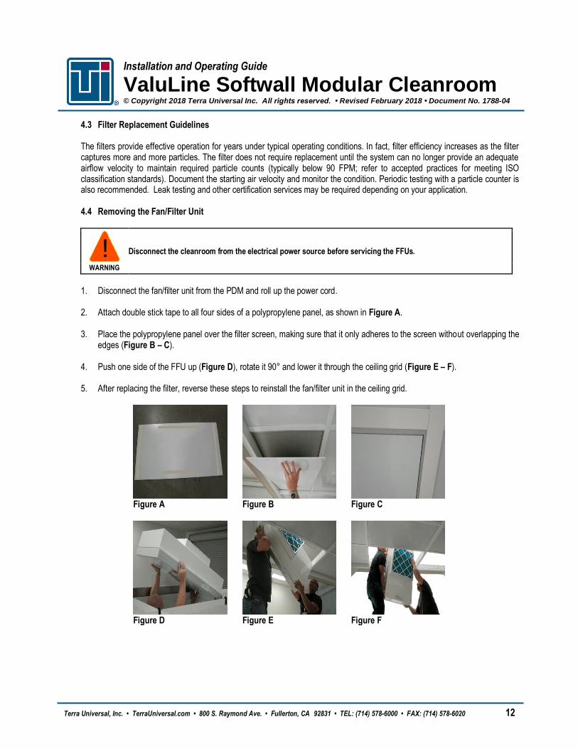
1. Disconnect the fan/filter unit from the PDM and roll up the power cord. 2. Attach double stick tape to all four sides of a polypropylene panel, as shown in Figure A. 3. Place the polypropylene panel over the filter screen, making sure that it only adheres to the screen without overlapping the
edges (Figure B – C). 4. Push one side of the FFU up (Figure D), rotate it 90° and lower it through the ceiling grid (Figure E – F). 5. After replacing the filter, reverse these steps to reinstall the fan/filter unit in the ceiling grid.
Figure A Figure B Figure C
Figure D Figure E Figure F

Installation and Operating Guide
ValuLine Softwall Modular Cleanroom © Copyright 2018 Terra Universal Inc. All rights reserved. • Revised February 2018 • Document No. 1788-04
Terra Universal, Inc. • TerraUniversal.com • 800 S. Raymond Ave. • Fullerton, CA 92831 • TEL: (714) 578-6000 • FAX: (714) 578-6020 13
4.5 Replacing the HEPA Filter
The standard filter is protected with an expanded metal face screen. This is never to be used to handle the filter. It is only for protection against an accidental touch of the filter. Handle the filter only by the frame.
CAUTION
Figure 11. Standard Fan/Filter Unit
1. Disconnect the yellow power cable and remove the unit from the ceiling.
2. Remove the 10 screws holding the HEPA / ULPA filter to the lid assembly.
3. Lift the lid assembly off the HEPA / ULPA filter. Discard the used filter as per applicable regulations.
4. Carefully attach the new filter, being sure not to touch or otherwise damage the filter face.
5. Lift out the old pre-filter and drop in the new one.
6. Position the unit back in the ceiling grid and reconnect the unit to its power supply
NOTE
Carefully inspect the new filter for any visible damage prior to replacing.
Pre-filter
HEPA Filter
Remove screws along both sides of the FFU

Installation and Operating Guide
ValuLine Softwall Modular Cleanroom © Copyright 2018 Terra Universal Inc. All rights reserved. • Revised February 2018 • Document No. 1788-04
Terra Universal, Inc. • TerraUniversal.com • 800 S. Raymond Ave. • Fullerton, CA 92831 • TEL: (714) 578-6000 • FAX: (714) 578-6020 14
5.0 Specifications
5.1 Fan Filter Units
Dimensions 23.63”W x 47.63”D x 13”H
Weight 71 lbs. (32 kg)
Avg. Airflow 717 CFM
Airflow Speed 115 fpm @ High 102 fpm @ Medium 93 fpm @ Low
Run Amps 4.3 amps @ High 3.5 amps @ Medium 3.3 amps @ Low
Power Requirements 120VAC, 60Hz
Sound Level Approximately 50 dBA on low speed measure at 30 in. from the filter face, with the fan delivering an average airflow velocity of 90 FPM (0.45 m/s)
Housing Both the fan plenum and filter housing have a powder-coated steel exterior
Pre-filter 20” x 20” x 1” MERV 7 pleated cotton/synthetic fibers
HEPA Filter Factory tested and rated 99.99% efficient in removal of particles 0.3 micron and larger; leak free in accordance with the latest I.E.S.T. Recommended Practices
Filter Media Micro-glass fiber with hot melt separators, sealed to the aluminum housing
Filter Screen Perforated stainless steel
Fan Direct Drive; forward curve centrifugal type with permanently lubricates sealed ball bearings
Motor Permanent split capacitor type rated for continuous duty furnished with thermal overload protection and a three-speed switch
5.2 UL-Listed Components If your order included UL documentation (Cat. # 6600-33), labels indicating UL-listed components can be found on the main power switch.

Installation and Operating Guide
ValuLine Softwall Modular Cleanroom © Copyright 2018 Terra Universal Inc. All rights reserved. • Revised February 2018 • Document No. 1788-04
Terra Universal, Inc. • TerraUniversal.com • 800 S. Raymond Ave. • Fullerton, CA 92831 • TEL: (714) 578-6000 • FAX: (714) 578-6020 15
6.0 Warranty
Products Manufactured by Terra: Terra Universal, Inc., warrants products that it manufactures to be free from defects for a period of 12 months for parts and 90 days for labor, commencing from the date of shipment. Terra’s sole responsibility is to repair or replace, at its option, any part of the product that proves defective or malfunctioning during this time limit. In some cases, components incorporated in Terra Universal products are covered by additional warranties from component manufacturers; obtain specific information from Terra sales representatives. This warranty is void if the equipment is abused or modified by the customer, is operated outside Terra’s operating instructions or specifications, or is used in any application other than that for which it is specified. This warranty does not include routine maintenance or service procedures, breakage of quartz baths after 60 days, shipping damage, nor damage from misuse, intentional or unintentional abuse, neglect, natural disasters, or acts of God. Products Manufactured by Others: Terra Universal, Inc., warrants that, to the best of its ability, Terra’s representations of products that are manufactured by others reflect the manufacturer’s representations, subject to change without notice. Sole warranty for these products is the original manufacturer’s warranty that is passed forward to the purchaser and constitutes the customer’s sole remedy for these products. Detailed warranties for distributed products are available through Terra sales representatives. Freight Shortage or Damage: Upon receipt of any equipment from Terra Universal, Inc., customer shall immediately unpack and inspect for damage or shortage. The customer shall not accept a damaged package or a short shipment until the carrier makes a "damage or shortage" notation on both the carrier's and customer's copy of the freight bill or delivery receipt. Service title passes when the shipment is loaded, so customer is responsible for filing and collecting a freight claim. Any replacement products must be ordered and paid for separately. For Terra's "Policy and Procedures for Returning Goods," see Terra's Internet site: www.TerraUniversal.com. Generally, customers can improve the chance of collecting on a freight claim by following these procedures: 1) formally requesting that the carrier inspect the shipment immediately upon suspecting damage or shortage to verify condition; 2) notifying the carrier upon discovery of concealed damage and requesting an inspection within 15 days of receipt, both in person or phone and following up via mail; 3) keeping the shipment as intact as possible, including retaining original packaging materials and keeping the product as close to the original receiving location as possible; 4) holding salvage for disposition by the carrier. All Claims: Terra Universal expressly disclaims all other warranties, expressed or implied or implied by statute, including the warranties of merchantability or fitness for intended use. Terra Universal is not responsible for consequential or incidental damages arising out of the purchase or use of the products supplied by Terra Universal. Terra Universal is not liable for damage to facilities, other equipment, products, property or personnel of others, or of their agents, suppliers, or affiliated parties, which is caused or alleged to have been caused by products supplied by Terra Universal. In any event or series of events, Terra Universal’s total liability for any and all damages whatsoever is limited to the lesser of the actual damages or the original invoice cost of the items alleged to have caused the damage. The customer’s sole and exclusive remedy for any cause of action whatsoever is repair or replacement of the non-conforming products or refund of the actual purchase price, at the sole option of Terra Universal. All claims must be made in writing within 90 days of the date the product was shipped. Any claims not made within this time limit shall be deemed waived by the customer. Terra Universal is not responsible for any additional costs of repair caused by poor packaging or in-shipment damage during return. Warranty Returns: All warranty returns must be authorized in advance by Terra Universal and approved under an RMA. Unless approved in advance for good reason, all returns must be in original condition, including all manuals, and must be packaged in original packaging materials. All returned goods are to be shipped to Terra Universal, freight prepaid at custome r’s expense. See Terra’s “Policy and Procedure for Returned Goods.”
Thank you for ordering from Terra Universal!
Installation and Operating Guide
ValuLine Softwall Modular Cleanroom © Copyright 2018 Terra Universal Inc. All rights reserved. • Revised February 2018 • Document No. 1788-04
Terra Universal, Inc. • TerraUniversal.com • 800 S. Raymond Ave. • Fullerton, CA 92831 • TEL: (714) 578-6000 • FAX: (714) 578-6020 16
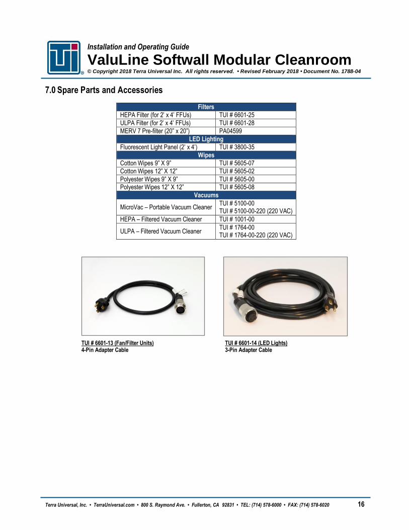
7.0 Spare Parts and Accessories
Filters
HEPA Filter (for 2’ x 4’ FFUs) TUI # 6601-25
ULPA Filter (for 2’ x 4’ FFUs) TUI # 6601-28
MERV 7 Pre-filter (20” x 20”) PA04599
LED Lighting
Fluorescent Light Panel (2’ x 4’) TUI # 3800-35
Wipes
Cotton Wipes 9” X 9” TUI # 5605-07
Cotton Wipes 12” X 12” TUI # 5605-02
Polyester Wipes 9” X 9” TUI # 5605-00 Polyester Wipes 12” X 12” TUI # 5605-08
Vacuums
MicroVac – Portable Vacuum Cleaner TUI # 5100-00 TUI # 5100-00-220 (220 VAC)
HEPA – Filtered Vacuum Cleaner TUI # 1001-00
ULPA – Filtered Vacuum Cleaner TUI # 1764-00 TUI # 1764-00-220 (220 VAC)
TUI # 6601-13 (Fan/Filter Units) 4-Pin Adapter Cable
TUI # 6601-14 (LED Lights) 3-Pin Adapter Cable

Installation and Operating Guide
ValuLine Softwall Modular Cleanroom © Copyright 2018 Terra Universal Inc. All rights reserved. • Revised February 2018 • Document No. 1788-04
Terra Universal, Inc. • TerraUniversal.com • 800 S. Raymond Ave. • Fullerton, CA 92831 • TEL: (714) 578-6000 • FAX: (714) 578-6020 17
8.0 Hardware Reference Table
Part Used For
#12 – ¾” Stainless Steel Self-Tapping Hex Head Screw
Ceiling Joists
Top Trim
Wall Panel Mounting Brackets
Set Screw (Allen)
Frame Assembly
Joist Divider Clip
Ceiling Joists and Dividers