Embed Size (px)
Citation preview
1
WARNING: To ensure that drive is not unexpectedly started, turn off and lock out or tag power source before proceeding. Remove all external loads from drive before removing or servicing drive or accessories. Failure to observe these precautions could result in bodily injury.
BUSHING INSTALLATION
The Dodge Torque-Arm II Reducer is designed to fit both standard and short length driven shafts. The Standard Taper Bushings series is designed where shaft length is not a concern. The Short Shaft Bushing series is to be used where the driven shaft does not extend through the reducer.
Standard Taper Bushings
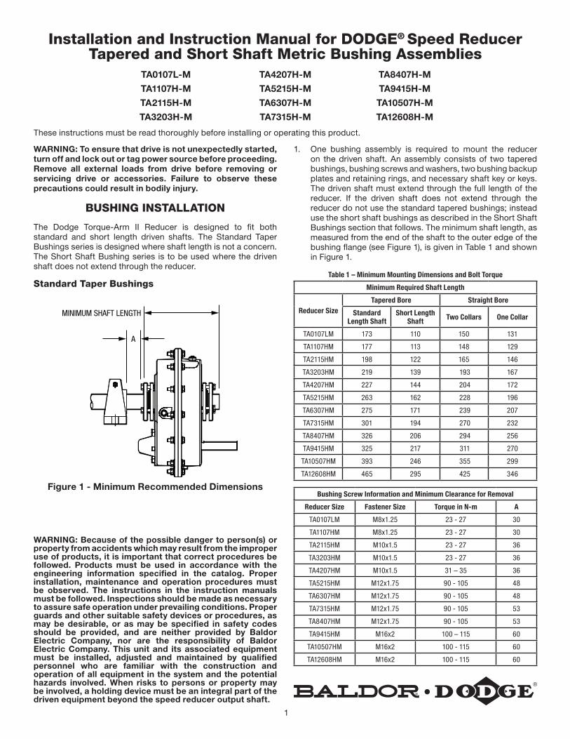
A
MINIMUM SHAFT LENGTH
Figure 1 - Minimum Recommended Dimensions
WARNING: Because of the possible danger to person(s) or property from accidents which may result from the improper use of products, it is important that correct procedures be followed. Products must be used in accordance with the engineering information specified in the catalog. Proper installation, maintenance and operation procedures must be observed. The instructions in the instruction manuals must be followed. Inspections should be made as necessary to assure safe operation under prevailing conditions. Proper guards and other suitable safety devices or procedures, as may be desirable, or as may be specified in safety codes should be provided, and are neither provided by Baldor Electric Company, nor are the responsibility of Baldor Electric Company. This unit and its associated equipment must be installed, adjusted and maintained by qualified personnel who are familiar with the construction and operation of all equipment in the system and the potential hazards involved. When risks to persons or property may be involved, a holding device must be an integral part of the driven equipment beyond the speed reducer output shaft.
Installation and Instruction Manual for DODGE® Speed Reducer Tapered and Short Shaft Metric Bushing Assemblies
TA0107L-M TA4207H-M TA8407H-M
TA1107H-M TA5215H-M TA9415H-M
TA2115H-M TA6307H-M TA10507H-M
TA3203H-M TA7315H-M TA12608H-M
These instructions must be read thoroughly before installing or operating this product.
1. One bushing assembly is required to mount the reducer on the driven shaft. An assembly consists of two tapered bushings, bushing screws and washers, two bushing backup plates and retaining rings, and necessary shaft key or keys. The driven shaft must extend through the full length of the reducer. If the driven shaft does not extend through the reducer do not use the standard tapered bushings; instead use the short shaft bushings as described in the Short Shaft Bushings section that follows. The minimum shaft length, as measured from the end of the shaft to the outer edge of the bushing flange (see Figure 1), is given in Table 1 and shown in Figure 1.
Table 1 – Minimum Mounting Dimensions and Bolt Torque
Minimum Required Shaft Length
Reducer SizeTapered Bore Straight Bore
Standard Length Shaft
Short Length Shaft Two Collars One Collar
TA0107LM 173 110 150 131
TA1107HM 177 113 148 129
TA2115HM 198 122 165 146
TA3203HM 219 139 193 167
TA4207HM 227 144 204 172
TA5215HM 263 162 228 196
TA6307HM 275 171 239 207
TA7315HM 301 194 270 232
TA8407HM 326 206 294 256
TA9415HM 325 217 311 270
TA10507HM 393 246 355 299
TA12608HM 465 295 425 346
Bushing Screw Information and Minimum Clearance for Removal
Reducer Size Fastener Size Torque in N-m A
TA0107LM M8x1.25 23 - 27 30
TA1107HM M8x1.25 23 - 27 30
TA2115HM M10x1.5 23 - 27 36
TA3203HM M10x1.5 23 - 27 36
TA4207HM M10x1.5 31 – 35 36
TA5215HM M12x1.75 90 - 105 48
TA6307HM M12x1.75 90 - 105 48
TA7315HM M12x1.75 90 - 105 53
TA8407HM M12x1.75 90 - 105 53
TA9415HM M16x2 100 – 115 60
TA10507HM M16x2 100 - 115 60
TA12608HM M16x2 100 - 115 60
2
2. Install one bushing backup plate on the end of the hub and secure with the supplied retaining ring. Repeat procedure for other side.
3. Place one bushing, flange end first, onto the driven shaft and position per dimension “A”, as shown in Table 1. This will allow the bolts to be threaded into the bushing for future bushing and reducer removal.
4. Insert the output key in the shaft and bushing. For ease of installation, rotate the driven shaft so that the shaft keyseat is at the top position.
5. Mount the reducer on the driven shaft and align the shaft key with the reducer hub keyway. Maintain the recommended minimum distance “A” from the shaft bearing.
6. Insert the screws, with washers installed, in the unthreaded holes in the bushing flange and align with the threaded holes in the bushing backup plate. If necessary, rotate the bushing backup plate to align with the bushing screws. Tighten the screws lightly. If the reducer must be positioned closer than dimension “A”, place the screws with washers installed, in the unthreaded holes in the bushing before positioning reducer making sure to maintain at least 3mm between the screw heads and the bearing.
7. Place the second tapered bushing in position on the shaft and align the bushing keyway with the shaft key. Align the unthreaded holes in the bushing with the threaded holes in the bushing backup plate. If necessary, rotate the bushing backup plate to align with the bushing holes. Insert bushing screws, with washers installed in the unthreaded holes in the bushing. Tighten screws lightly.
8. Alternately and evenly tighten the screws in the bushing nearest the equipment to the recommended torque given in Table 1. Repeat procedure on outer bushing.
Short Shaft Bushings
1. One bushing assembly is required to mount the reducer on the driven shaft. An assembly consists of one long tapered bushing, one short tapered bushing, one tapered bushing wedge, bushing screws and washers, two bushing backup plates and retaining rings, and necessary shaft key or keys. The driven shaft does not need to extend through the reducer for the short shaft bushing to operate properly. The minimum shaft length, as measured from the end of the shaft to the outer edge of the bushing flange (see Figure 1), is given in Table 1.
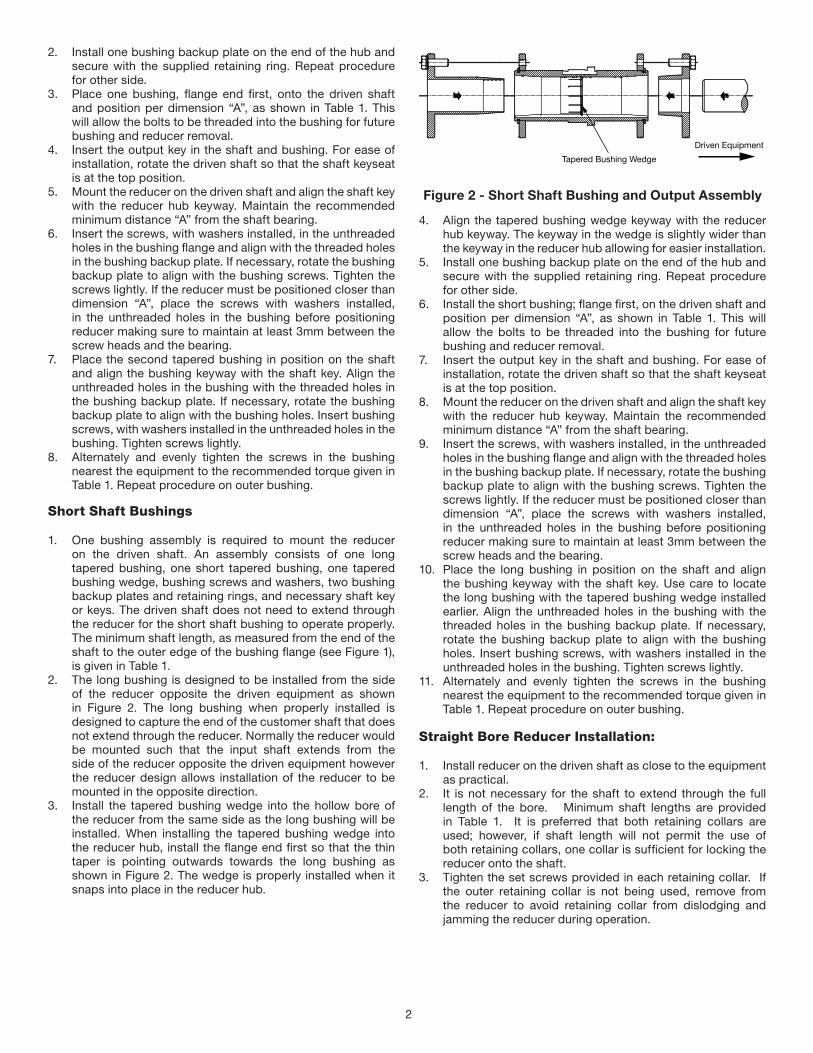
2. The long bushing is designed to be installed from the side of the reducer opposite the driven equipment as shown in Figure 2. The long bushing when properly installed is designed to capture the end of the customer shaft that does not extend through the reducer. Normally the reducer would be mounted such that the input shaft extends from the side of the reducer opposite the driven equipment however the reducer design allows installation of the reducer to be mounted in the opposite direction.
3. Install the tapered bushing wedge into the hollow bore of the reducer from the same side as the long bushing will be installed. When installing the tapered bushing wedge into the reducer hub, install the flange end first so that the thin taper is pointing outwards towards the long bushing as shown in Figure 2. The wedge is properly installed when it snaps into place in the reducer hub.
Tapered Bushing Wedge
Driven Equipment
Figure 2 - Short Shaft Bushing and Output Assembly
4. Align the tapered bushing wedge keyway with the reducer hub keyway. The keyway in the wedge is slightly wider than the keyway in the reducer hub allowing for easier installation.
5. Install one bushing backup plate on the end of the hub and secure with the supplied retaining ring. Repeat procedure for other side.
6. Install the short bushing; flange first, on the driven shaft and position per dimension “A”, as shown in Table 1. This will allow the bolts to be threaded into the bushing for future bushing and reducer removal.
7. Insert the output key in the shaft and bushing. For ease of installation, rotate the driven shaft so that the shaft keyseat is at the top position.
8. Mount the reducer on the driven shaft and align the shaft key with the reducer hub keyway. Maintain the recommended minimum distance “A” from the shaft bearing.
9. Insert the screws, with washers installed, in the unthreaded holes in the bushing flange and align with the threaded holes in the bushing backup plate. If necessary, rotate the bushing backup plate to align with the bushing screws. Tighten the screws lightly. If the reducer must be positioned closer than dimension “A”, place the screws with washers installed, in the unthreaded holes in the bushing before positioning reducer making sure to maintain at least 3mm between the screw heads and the bearing.
10. Place the long bushing in position on the shaft and align the bushing keyway with the shaft key. Use care to locate the long bushing with the tapered bushing wedge installed earlier. Align the unthreaded holes in the bushing with the threaded holes in the bushing backup plate. If necessary, rotate the bushing backup plate to align with the bushing holes. Insert bushing screws, with washers installed in the unthreaded holes in the bushing. Tighten screws lightly.
11. Alternately and evenly tighten the screws in the bushing nearest the equipment to the recommended torque given in Table 1. Repeat procedure on outer bushing.
Straight Bore Reducer Installation:
1. Install reducer on the driven shaft as close to the equipment as practical.
2. It is not necessary for the shaft to extend through the full length of the bore. Minimum shaft lengths are provided in Table 1. It is preferred that both retaining collars are used; however, if shaft length will not permit the use of both retaining collars, one collar is sufficient for locking the reducer onto the shaft.
3. Tighten the set screws provided in each retaining collar. If the outer retaining collar is not being used, remove from the reducer to avoid retaining collar from dislodging and jamming the reducer during operation.

3
Bushing Removal for Standard Taper or Short ShaftBushings:
1. Remove bushing screws.2. Place the screws in the threaded holes provided in the
bushing flanges. Tighten the screws alternately and evenly until the bushings are free on the shaft. For ease of tightening screws make sure screw threads and thread holes in the bushing flanges are clean. If the reducer was positioned closer than the recommended minimum distance “A” as shown in Table 1, loosen the inboard bushing screws until they are clear of the bushing flange by 3mm. Locate two (2) wedges at 180 degrees between the bushing flange and the bushing backup plate. Drive the wedges alternately and evenly until the bushing is free on the shaft.
3. Remove the outside bushing, the reducer, and then the inboard bushing.
Straight Bore Reducer Removal:
1. Loosen screws in retaining collars as applicable.2. If both retaining collars are installed, remove the outer
retaining collar. This will expose three puller holes in the output hub.
3. Install a three-jaw puller and remove reducer from shaft. Use caution not to damage the output hub during reducer removal.

P.O. Box 2400, Fort Smith, AR 72902-2400 U.S.A., Ph: (1) 479.646.4711, Fax (1) 479.648.5792, International Fax (1) 479.648.5895
Dodge Product Support
6040 Ponders Court, Greenville, SC 29615-4617 U.S.A., Ph: (1) 864.297.4800, Fax: (1) 864.281.2433
www.baldor.com
All Rights Reserved. Printed in USA.5/12 Trophy 1000
© Baldor Electric CompanyMN16005 *16005-0512*


![[D2 CAMPUS] Dodge the Dodge - GoN](https://img.dokumen.tips/doc/110x75/58700cdc1a28ab427f8b766f/d2-campus-dodge-the-dodge-gon.jpg)