Embed Size (px)
Citation preview
Contents 1. Introduction, Installation and the Initial Setup of WPLSoft
1.1. Introduction & System Requirement ..................................................................................1 1.2. System Installation & Setup...............................................................................................1 1.3. Program Execution ............................................................................................................7 1.4. Initial Setup........................................................................................................................8
2. Introduction on the Function Panel 2.1. File (F)............................................................................................................................. 12 2.2. Communication (C).......................................................................................................... 13 2.3. Option (O)........................................................................................................................ 16 2.4. Windows (W) ................................................................................................................... 17 2.5. Help (H) ........................................................................................................................... 18 2.6. Edit (E) ............................................................................................................................ 18 2.7. Compile (P) ..................................................................................................................... 21 2.8. Comment (L) ................................................................................................................... 22 2.9. Search (S) ....................................................................................................................... 23 2.10. View (V) ......................................................................................................................... 24
3. Create New Files, Open Old Files and Save Files 3.1. New................................................................................................................................. 26 3.2. Open ............................................................................................................................... 27 3.3. Save ................................................................................................................................ 29 3.4. Save As........................................................................................................................... 29
4. The Ladder Diagram Editing Mode 4.1. Conditions of the Ladder Diagram Editing Mode.............................................................. 31 4.2. Basic Operation ............................................................................................................... 33 4.3. Editing Example............................................................................................................... 36 4.4. Auxiliary Editing ............................................................................................................... 39
5. The Command Editing Mode 5.1. Conditions of the Command Editing Mode....................................................................... 55 5.2. Basic Operation ............................................................................................................... 55 5.3. Auxiliary Editing ............................................................................................................... 57
6. Comment Editing 6.1. Device Comment ............................................................................................................. 71 6.2. Line Comment ................................................................................................................. 76 6.3. Block Comment ............................................................................................................... 78

7. Communication Connection Mode 7.1. Data Transmission........................................................................................................... 80 7.2. Program Verification ........................................................................................................ 83 7.3. Password......................................................................................................................... 84 7.4. PLC RUN/STOP ..............................................................................................................85 7.5. Ladder Diagram Monitor .................................................................................................. 86 7.6. SFC Monitor .................................................................................................................... 89 7.7. Device Monitor................................................................................................................. 90 7.8. Device Forced ON/OFF ................................................................................................... 93 7.9. Current Value Setting....................................................................................................... 97 7.10. Edit Register ................................................................................................................ 100 7.11. PLC Memory Clear....................................................................................................... 102 7.12. PLC Information ........................................................................................................... 104
8. SFC Editing Mode 8.1. Conditions of the SFC Editing Mode .............................................................................. 105 8.2. Basic Operation ............................................................................................................. 105 8.3. Auxiliary Editing ............................................................................................................. 120
9. Appendix Data 1 Operation Key and the Speedy Key-in Functions.................................................... 129 Data 2 Example Program ................................................................................................... 132 Data 3 Index Function ........................................................................................................ 134

1. Introduction, Installation and the Initial Setup of WPLSoft
© 2001 DELTA ELECTRONICS, INC. ALL RIGHTS RESERVED 1
1.1 Introduction &&&& System Requirement:
WPLSoft is a program-editing software made for the Delta DVP-PLC series used under WINDOWS. Except for general program planning and other general functions (e.g. cut, paste, copy, multi-windows, etc.) of WINDOWS, WPLSoft, in addition, has provided various Chinese/English commentary-editing and other special functions (e.g. survey and edit the listed register, the setup, the data readout, the file saving, and monitor and set up diagrams of various contacts, etc.).
What follows is the system requirement to comply with the operation environment of WPLSoft:
Item System Requirement
Operation system Windows 95/98/2000/NT/ME
CPU Pentium 90 or above
Memory 16MB or above (32MB or above is recommended)
Hard drive Capacity: at least 50MB or above CD-ROM (to install WPLSoft)
Monitor Resolution: 640×480, 16 colors or above
Mouse Mouse of general use or the device compatible with Windows
Printer With the driver program of Windows installed
RS-232 port At least one of the ports among COM1 ~ COM4 should be connected with PLC
Compatible PLC model The Delta DVP-PLC Series
1.2 System Installation &&&& Setup
【Method 1:】 File Installation
1. Start Windows 95/98/2000/NT/ME.
2. Put WPLSoft CD-ROM into the CD-ROM drive.
3. Press “START” button, and click on “RUN”.

1. Introduction, Installation and the Initial Setup of WPLSoft
© 2001 DELTA ELECTRONICS, INC. ALL RIGHTS RESERVED 2
1. Press "START"
2. Click on "RUN"
4. Designate the drive and location where WPLSoft is to be installed and saved.
Key in the site where WPL is to install the setupexecution file
Setup Initialization 5. Afterwards, it is the message box explaining the WPLSoft copyright and the system
requirement; users could press the “Next>” button to proceed with the installation.

1. Introduction, Installation and the Initial Setup of WPLSoft
© 2001 DELTA ELECTRONICS, INC. ALL RIGHTS RESERVED 3
6. Key in the user name and the company name, then press “Next>” to proceed.
User Name
Company Name
7. For the following procedure, simply press the “Next>” button to proceed.
The WPL Destination Directory Setup

1. Introduction, Installation and the Initial Setup of WPLSoft
© 2001 DELTA ELECTRONICS, INC. ALL RIGHTS RESERVED 4
WPL Program Folder Setup

1. Introduction, Installation and the Initial Setup of WPLSoft
© 2001 DELTA ELECTRONICS, INC. ALL RIGHTS RESERVED 5
Lastly, press the “Finish” button to complete the installation.
【Method 2:】AUTO-RUN Installation
1. Start Windows 95/98/2000/NT/ME.
2. Put the WPLSoft CD-ROM into the CD drive.
3. If the CD drive supports the AUTO-RUN function, what appears next is the WPLSoft installation program connector.
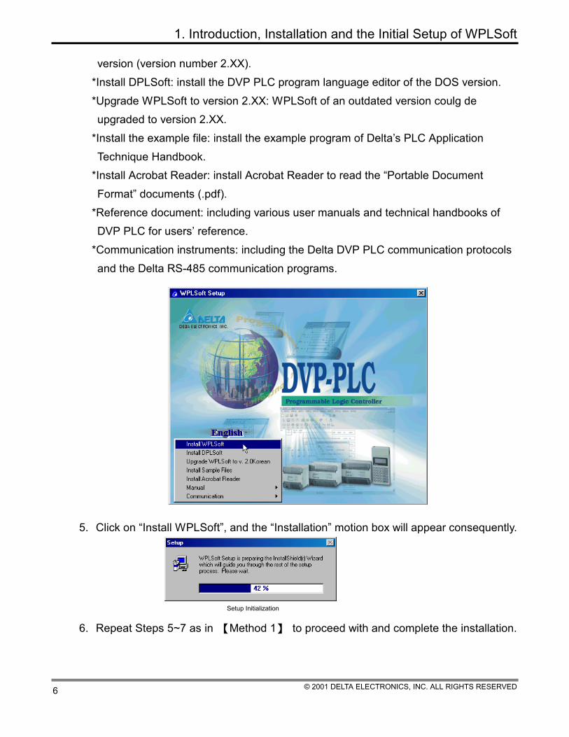
4. Click on “English”, and the following selections will show up: *Install WPLSoft: install the DVP PLC program language editor of the WINDOWS
1. Introduction, Installation and the Initial Setup of WPLSoft
© 2001 DELTA ELECTRONICS, INC. ALL RIGHTS RESERVED 6
version (version number 2.XX). *Install DPLSoft: install the DVP PLC program language editor of the DOS version. *Upgrade WPLSoft to version 2.XX: WPLSoft of an outdated version coulg de upgraded to version 2.XX.
*Install the example file: install the example program of Delta’s PLC Application Technique Handbook.
*Install Acrobat Reader: install Acrobat Reader to read the “Portable Document Format” documents (.pdf).
*Reference document: including various user manuals and technical handbooks of DVP PLC for users’ reference.
*Communication instruments: including the Delta DVP PLC communication protocols and the Delta RS-485 communication programs.
5. Click on “Install WPLSoft”, and the “Installation” motion box will appear consequently.
Setup Initialization 6. Repeat Steps 5~7 as in 【Method 1】 to proceed with and complete the installation.
1. Introduction, Installation and the Initial Setup of WPLSoft
© 2001 DELTA ELECTRONICS, INC. ALL RIGHTS RESERVED 7
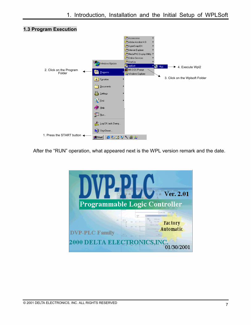
1.3 Program Execution
1. Press the START button
2. Click on the Program Folder
3. Click on the Wplsoft Folder
4. Execute Wpl2
After the “RUN” operation, what appeared next is the WPL version remark and the date.
1. Introduction, Installation and the Initial Setup of WPLSoft
© 2001 DELTA ELECTRONICS, INC. ALL RIGHTS RESERVED 8
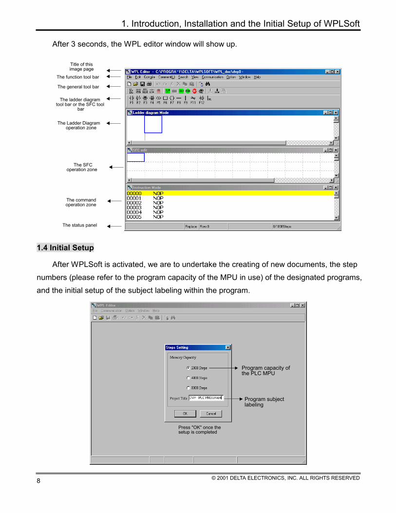
After 3 seconds, the WPL editor window will show up.
Title of this image page
The general tool bar
The ladder diagram tool bar or the SFC tool
bar
The function tool bar
The Ladder Diagram operation zone
The command operation zone
The status panel
The SFC operation zone
1.4 Initial Setup
After WPLSoft is activated, we are to undertake the creating of new documents, the step numbers (please refer to the program capacity of the MPU in use) of the designated programs, and the initial setup of the subject labeling within the program.
Program subject labeling
Program capacity ofthe PLC MPU
Press "OK" once the setup is completed

1. Introduction, Installation and the Initial Setup of WPLSoft
© 2001 DELTA ELECTRONICS, INC. ALL RIGHTS RESERVED 9
After the setting is completed, three windows will show up: one is the Ladder Diagram Mode Window, the other is the Command Mode Window, and the third one is the SFC Editing Mode. Users are to choose the editing mode of their interests to proceed with the PLC program editing.
The Ladder Diagram Mode: (after the ladder diagram is edited, convert the ladder diagram to the command mode and the SFC diagram through compiling)
The WPL preset filename The program subjec labelling
The Command Mode: (after the command is edited, convert it to the ladder diagram and the SFC diagram through compiling)

1. Introduction, Installation and the Initial Setup of WPLSoft
© 2001 DELTA ELECTRONICS, INC. ALL RIGHTS RESERVED 10
The WPL preset filename The program title labelling
The SFC Mode: (after the SFC diagram is edited, convert it to the command code through compiling, and to convert it to the ladder diagram, users have to go through the command code compiling in order to achieve the ladder diagram conversion)
2. Introduction on the Function Panel
© 2001 DELTA ELECTRONICS, INC. ALL RIGHTS RESERVED 11
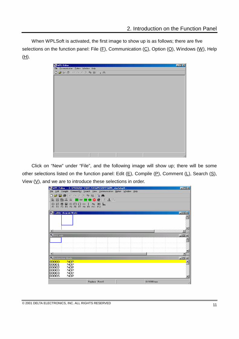
When WPLSoft is activated, the first image to show up is as follows; there are five selections on the function panel: File (F), Communication (C), Option (O), Windows (W), Help (H).
Click on “New” under “File”, and the following image will show up; there will be some other selections listed on the function panel: Edit (E), Compile (P), Comment (L), Search (S), View (V), and we are to introduce these selections in order.
2. Introduction on the Function Panel
© 2001 DELTA ELECTRONICS, INC. ALL RIGHTS RESERVED 12
2.1 File
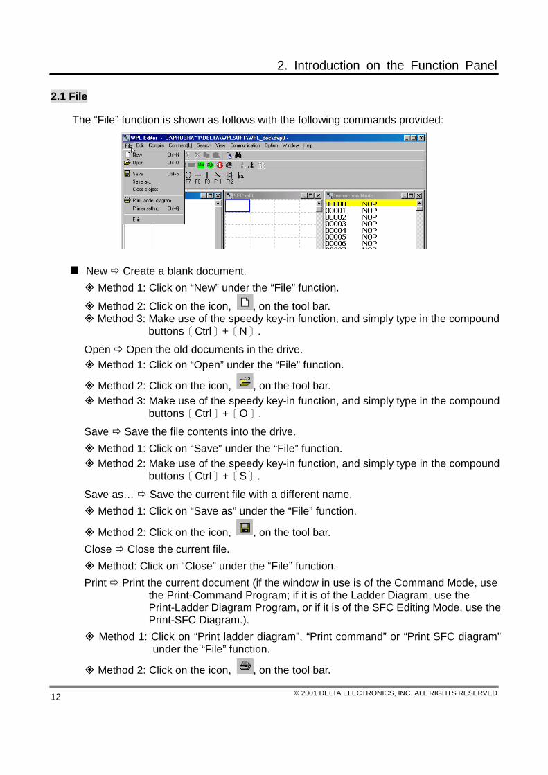
The “File” function is shown as follows with the following commands provided:
New Create a blank document. Method 1: Click on “New” under the “File” function.
Method 2: Click on the icon, , on the tool bar. Method 3: Make use of the speedy key-in function, and simply type in the compound
buttons〔Ctrl〕+〔N〕.
Open Open the old documents in the drive. Method 1: Click on “Open” under the “File” function.
Method 2: Click on the icon, , on the tool bar. Method 3: Make use of the speedy key-in function, and simply type in the compound
buttons〔Ctrl〕+〔O〕.
Save Save the file contents into the drive. Method 1: Click on “Save” under the “File” function. Method 2: Make use of the speedy key-in function, and simply type in the compound
buttons〔Ctrl〕+〔S〕.
Save as… Save the current file with a different name. Method 1: Click on “Save as” under the “File” function.
Method 2: Click on the icon, , on the tool bar. Close Close the current file.
Method: Click on “Close” under the “File” function. Print Print the current document (if the window in use is of the Command Mode, use
the Print-Command Program; if it is of the Ladder Diagram, use the Print-Ladder Diagram Program, or if it is of the SFC Editing Mode, use the Print-SFC Diagram.).
Method 1: Click on “Print ladder diagram”, “Print command” or “Print SFC diagram” under the “File” function.
Method 2: Click on the icon, , on the tool bar.

2. Introduction on the Function Panel
© 2001 DELTA ELECTRONICS, INC. ALL RIGHTS RESERVED 13
Printer setting Select a printer and set up its connecting ports. Method 1: Click on “Printer setting” under the “File” function. Method 2: Make use of the speedy key-in function, and simply type in the compound
buttons〔Ctrl〕+〔Q〕.
Exit END WPLSoft. Method 1: Click on “Exit” under the “File” function. Method 2: Click on the icon,X, that locates on the upper right corner of the window.
Method 3: Make use of the speedy key-in function, and simply type in the compound buttons〔Alt〕+〔F4〕.
File Explanation:
The program is to be saved after the editing and compiling, and within WPLSoft, there will be the file type accompanied by 8 different sub-file names for selection; actual files will vary according to the differences on the user-edited files.
* .DVP Program code – execution file; the file generated after the ladder diagram program has gone through a successful compiling.
* .LAD The ladder-diagram editing file. * .LMT The ladder-diagram zone labeling record file. * .RMT The ladder-diagram device labeling record file. * .LAB The Label record file. * .BMT The label record file of Labels P and I. * .SMT The ladder-diagram output label record file. * .RVL The register’s data record file.
For general programs that request a thorough backup file, it is necessary to copy the above-mentioned 8 files to make it complete. And to get a basic backup file, it is required to save those files with DVP as their sub-file names (* .DVP); what the user has to do is to use WPLSoft to reload this file, then compile, and in the end, files with sub-file names LAB and LAD (* .LAB and * .LAD) would be generated. If the conversion of the user-edited ladder diagram program is not successful but has to be saved still, it is thus required to save those files with the sub-file name LAD (* .LAD ) all together when the backup file is saved. If the user does edit the label and would like to view the complete labeling within the backup program, the label record file has to be saved as well. 2.2 Communication
The “Communication” function is shown as follows, with the following commands rovided:

2. Introduction on the Function Panel
© 2001 DELTA ELECTRONICS, INC. ALL RIGHTS RESERVED 14
PC<=>(PLC | HPP) The communication between PC and PLC or PC and HPP are meant for the readout or write-in of programs.
Method 1: Click on “PC〈=〉(PLC∣HPP)” under the “Communication” function.
Method 2: Click on the icon, , on the tool bar. Method 3: Make use of the speedy key-in function, and simply type in the compound
buttons〔Ctrl〕+〔F1〕.
Program verification Verify whether the programs within PLC are the same as those in the process of editing.
Method: Click on “Program verification” under the “Communication” function.
Password Setup or remove the PLC password. Method: Click on the “Password” under the “Communication” function.
PLC Run Execute the PLC. Method 1: Click on “PLC Run” under the “Communication” function.
Method 2: Click on the icon, , on the tool bar. Method 3: Make use of the speedy key-in function, and simply type in the compound
buttons〔Ctrl〕+〔F5〕.
PLC Stop Stop the execution of PLC. Method 1: Click on “PLC Stop” under the “Communication” function.
Method 2: Click on the icon, , on the tool bar. Method 3: Make use of the speedy key-in function, and simply type in the compound
buttons〔Ctrl〕+〔F8〕.

2. Introduction on the Function Panel
© 2001 DELTA ELECTRONICS, INC. ALL RIGHTS RESERVED 15
Ladder diagram monitor start Switch to the monitor mode of the ladder diagram. (Only effective under the ladder diagram mode)
Method 1: Click on “Ladder diagram monitor start” or “Ladder diagram monitor stop” under the “Communication” function.
Click on the icon, , on the tool bar.
SFC monitor Switch to the monitor mode of the SFC editing mode. (Only effective under the SFC editing)
Method 1: Click on “SFC monitor start” or “SFC monitor stop” under the “Communication” function.
Click on the icon, , on the tool bar. Device monitor Switch to the device monitor window to get to know the status and
numeric values of the device to be monitored. Method 1: Click on “Device monitor” under the “Communication” function.
Click on the icon, , on the tool bar.
Force ON/OFF Force devices (Y, M, S, T and C) to be set as ON or OFF. (only effective under the ladder diagram mode or the device monitor mode)
Method 1: Click on “Force ON/OFF” under the “Communication” function. Method 2: Place the editing box upon the device, and press the right button on the
mouse to select “Force ON” or “Force OFF” function. Change current value Change the current value of the designated device register (T,
C and D). (Only effective under the ladder diagram monitor mode or the device monitor mode)
Method 1: Click on “Change current value” under the “Communication” function. Method 2: Place the editing box upon the device, and press the right button on the
mouse to select “Change current value” function. Edit register Proceed with functions such as read, write, print, file readout, and save
the file within internal registers (T, C and D) of the PLC. Method 1: Click on “Edit register” under the “Communication” function. Method 2: Make use of the speedy key-in function, and simply type in the compound
buttons〔Ctrl〕+〔Alt〕+〔D〕.
PLC memory clear Delete contents of the currently linked PLC program memory. (Only effective when PLC is at the STOP motion)
Method: Click on “PLC memory clear” under the “Communication” function.
PLC information Display in detail the currently linked PLC status, capacity, the PLC version, the communication address, the input/output extension points, and results of the syntax checkup.
Method: Click on “PLC information” under the “Communication” function.

2. Introduction on the Function Panel
© 2001 DELTA ELECTRONICS, INC. ALL RIGHTS RESERVED 16
2.3 Option
The “Option” function is shown as follows, with the following commands provided:
Communication port Use the RS232 ports (COM1, COM2, COM3 or COM4) of
PC to connect with PLC; it all depends on the condition of PC to decide which port to utilize.
Method: Click on “Communication port” under the “Option” function. Transmission speed Currently, the transmission speed between PC and PLC is
9600 bit/second. (Not supported for current models) Method 1: Click on “Transmission speed” under the “Option” function. Method 2: Make use of the speedy key-in function, and simply type in the
compound buttons〔Ctrl〕+〔Alt〕+〔S〕.
Memory capacity Set the MPU users’ program storage capacity. (Please refer to the program capacity of the MPU in use)
Method: Click on “Memory capacity” under the “Option” function.
PLC communication address In the scope of 0~255. (The factory setting is 1) Method: Click on “PLC communication address” under the “Option” function.
Transmission speed detect Detect the transmission speed between current PC and PLC. (Not supported for current models)
Method: Click on “Transmission speed detect” under the “Option” function. Auto Save Save the command program and the ladder diagram program before
compiling. Method: Click on “Auto Save” under the “Option” function.

2. Introduction on the Function Panel
© 2001 DELTA ELECTRONICS, INC. ALL RIGHTS RESERVED 17
2.4 Windows
The “Windows” function is shown as follows, with the following commands provided:
Cascade Arrange windows in an overlapping way. Method: Click on “Cascade” under the “Windows” function.
File horizontal Arrange the file in a horizontal way. Method: Click on “File horizontal” under the “Windows” function.
File vertical Arrange files in a vertical way. Method: Click on “File vertical” under the “Windows” function.
Data value type Set the register-displayed values in the Decimal system, the Hexadecimal system or the ASCII codes.
Method: Click on “Data value type” under the “Windows” function. (Could be used interchangeably within the ladder diagram monitoring/device monitoring modes)
Window size Change the display window sizes, which include 50%, 75%, 100%, 125%, 150%, 175% and 200%, along with the most suitable window size for users’ choices. (Only effective under the ladder diagram/SFC editing modes)
Method: Click on “Window size” under the “Windows” function. Window currently open by the editor e.g. the Ladder Diagram Mode, the
Command Mode, the SFC Editing, the Device Monitor, the Register Editing.
Method: Open the Ladder Diagram Mode, the Command Mode, the SFC Editing, the Device Monitor, the Register Editing with the WPL Editor, and consequently, they could all be displayed under the editor-opened window.

2. Introduction on the Function Panel
© 2001 DELTA ELECTRONICS, INC. ALL RIGHTS RESERVED 18
2.5 Help
The “Help” function is shown as follows, with the following commands provided:
About WPL Editor Display relevant information on the WPLSoft program versions.
Method: Click on “About WPL Editor” under the “Help” function.
Index Index browser is provided for users to obtain help on relevant topics. Method: Click on “Index” under the “Help” function.
2.6 Edit
The “Edit” function is shown as follows, with the following commands provided:
2. Introduction on the Function Panel
© 2001 DELTA ELECTRONICS, INC. ALL RIGHTS RESERVED 19
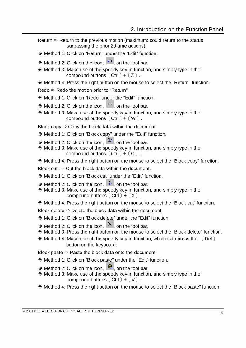
Return Return to the previous motion (maximum: could return to the status surpassing the prior 20-time actions).
Method 1: Click on “Return” under the “Edit” function.
Method 2: Click on the icon, , on the tool bar. Method 3: Make use of the speedy key-in function, and simply type in the
compound buttons〔Ctrl〕+〔Z〕. Method 4: Press the right button on the mouse to select the “Return” function.
Redo Redo the motion prior to “Return”. Method 1: Click on “Redo” under the “Edit” function.
Method 2: Click on the icon, , on the tool bar. Method 3: Make use of the speedy key-in function, and simply type in the
compound buttons〔Ctrl〕+〔W〕.
Block copy Copy the block data within the document. Method 1: Click on “Block copy” under the “Edit” function.
Method 2: Click on the icon, , on the tool bar. Method 3: Make use of the speedy key-in function, and simply type in the
compound buttons〔Ctrl〕+〔C〕. Method 4: Press the right button on the mouse to select the “Block copy” function.
Block cut: Cut the block data within the document. Method 1: Click on “Block cut” under the “Edit” function.
Method 2: Click on the icon, , on the tool bar. Method 3: Make use of the speedy key-in function, and simply type in the
compound buttons〔Ctrl〕+〔X〕. Method 4: Press the right button on the mouse to select the “Block cut” function.
Block delete Delete the block data within the document. Method 1: Click on “Block delete” under the “Edit” function.
Method 2: Click on the icon, , on the tool bar. Method 3: Press the right button on the mouse to select the “Block delete” function. Method 4: Make use of the speedy key-in function, which is to press the 〔Del〕
button on the keyboard. Block paste Paste the block data onto the document.
Method 1: Click on “Block paste” under the “Edit” function.
Method 2: Click on the icon, , on the tool bar. Method 3: Make use of the speedy key-in function, and simply type in the
compound buttons〔Ctrl〕+〔V〕. Method 4: Press the right button on the mouse to select the “Block paste” function.

2. Introduction on the Function Panel
© 2001 DELTA ELECTRONICS, INC. ALL RIGHTS RESERVED 20
Insert block Insert one block data into the document (only applicable with the Ladder Diagram Editing Mode).
Method 1: Click on “Insert block” under the “Edit” function. Method 2: Make use of the speedy key-in function, and simply type in the
compound buttons〔Ctrl〕+〔Ins〕。 Method 3: Press the right button on the mouse to select the “Insert block” function.
Insert one row Insert one blank row into the document. Method 1: Click on “Insert one row” under the “Edit” function. Method 2: Make use of the speedy key-in function, and simply type in the
compound buttons〔Ctrl〕+〔I〕. Method 3: Press the right button on the mouse to select the “Insert one row”
function. Delete a row Delete one row on the document.
Method 1: Click on “Delete a row” under the “Edit” function. Method 2: Make use of the speedy key-in function, and simply type in the
compound buttons〔Ctrl〕+〔Y〕. Method 3: Press the right button on the mouse to select the “Delete a row” function.
Item delete Delete one device on the document. (Only applicable with the Ladder Diagram Editing Mode)
Method 1: Click on “Item delete” under the “Edit” function. Method 2: Press the 〔Del〕 button on the keyboard, or make use of the speedy
key-in function, which is to type in the compound buttons〔Ctrl〕+〔Del〕. Method 3: Press the right button on the mouse to select the “Item delete” function.
Delete the vertical line Delete the vertical line on the document. (Only applicable with the Ladder Diagram Editing Mode)
Method 1: Click on “Delete the vertical line” under the “Edit” function. Method 2: Make use of the speedy key-in function, and simply type in the
compound buttons〔Ctrl〕+〔D〕. Method 3: Press the right button on the mouse to select the “Delete the vertical
line” function. Edit the program title Edit the title of the program.
Method 1: Click on “Edit the program title” under the “Edit” function. Method 2: Make use of the speedy key-in function, and simply type in the
compound buttons〔Ctrl〕+〔Alt〕+〔T〕. Insert one blank space Insert the space into one blank row. (Only applicable with
the SFC Editing Mode) Method 1: Click on “Insert one blank space” under the “Edit” function. Method 2: Make use of the speedy key-in function, and simply type in the
compound buttons〔Ctrl〕+〔B〕. Method 3: Press the right button on the mouse to select the “Insert one blank
space” function.

2. Introduction on the Function Panel
© 2001 DELTA ELECTRONICS, INC. ALL RIGHTS RESERVED 21
Delete one blank space Insert the space into one blank row. (Only applicable with the SFC Editing Mode)
Method 1: Click on “Delete one blank space” under the “Edit” function. Method 2: Make use of the speedy key-in function, and simply type in the
compound buttons〔Ctrl〕+〔K〕.
Method 3: Press the right button on the mouse to select the “Delete one blank space” function.
2.7 Compile
The “Compile” function is shown as follows, with the following commands provided:
Ladder Diagram -> Instruction Convert the Ladder Diagram program to the Command codes.
Method 1: Click on “Ladder Diagram -> Instruction” under the “Compile (P)” function.
Method 2: Click on the icon, , on the tool bar. Method 3: Make use of the speedy key-in function, and simply type in the
compound buttons〔Ctrl〕+〔F10〕.
Instruction -> Ladder Diagram Convert the Command codes to the Ladder Diagram program.
Method 1: Click on “Instruction -> Ladder Diagram” under the “Compile (P)” function.
Method 2: Click on the icon, , on the tool bar. Method 3: Make use of the speedy key-in function, and simply type in the
compound buttons〔Ctrl〕+〔F11〕.
SFC -> Instruction Convert the SFC diagram to the Command codes. (If the SFC diagram is to be converted to the ladder diagram, it is necessary to convert the SFC diagram to the command code first, and to consequently convert it to the ladder diagram program)
Method 1: Click on “SFC -> Instruction” under the “Compile (P)” function.
Method 2: Click on the icon, , on the tool bar.
2. Introduction on the Function Panel
© 2001 DELTA ELECTRONICS, INC. ALL RIGHTS RESERVED 22
Method 3: Make use of the speedy key-in function, and simply type in the compound buttons〔Ctrl〕+〔F6〕.
Double Loop Check Check the repetitive device usages of the OUT, SET, RST, TMR, CNT and DCNT commands.
Method: Click on “Double Loop Check” under the “Compile (P)” function.
2.8 Comment
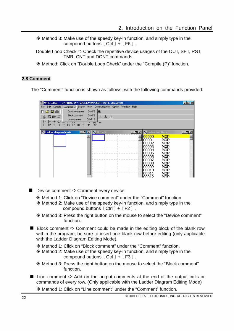
The “Comment” function is shown as follows, with the following commands provided:
Device comment Comment every device. Method 1: Click on “Device comment” under the “Comment” function. Method 2: Make use of the speedy key-in function, and simply type in the
compound buttons〔Ctrl〕+〔F2〕. Method 3: Press the right button on the mouse to select the “Device comment”
function. Block comment Comment could be made in the editing block of the blank row within the program; be sure to insert one blank row before editing (only applicable with the Ladder Diagram Editing Mode).
Method 1: Click on “Block comment” under the “Comment” function. Method 2: Make use of the speedy key-in function, and simply type in the
compound buttons〔Ctrl〕+〔F3〕. Method 3: Press the right button on the mouse to select the “Block comment”
function. Line comment Add on the output comments at the end of the output coils or commands of every row. (Only applicable with the Ladder Diagram Editing Mode)
Method 1: Click on “Line comment” under the “Comment” function.

2. Introduction on the Function Panel
© 2001 DELTA ELECTRONICS, INC. ALL RIGHTS RESERVED 23
Method 2: Make use of the speedy key-in function, and simply type in the compound buttons〔Ctrl〕+〔F12〕.
Method 3: Press the right button on the mouse to select the “Line comment” function.
2.9 Search
The “Search” function is shown as follows, with the following commands provided:
Jump Jump to the designated location (Take the Step as an unit). Method 1: Click on “Jump” under the “Search” function.
Method 2: Click on the icon, , on the tool bar. Method 3: Make use of the speedy key-in function, and simply type in the
compound buttons〔Ctrl〕+〔F〕.
Search/Replace Search or Replace the device name. Method 1: Click on “Search/Replace” under the “Search” function.
Method 2: Click on the icon, , on the tool bar. Method 3: Make use of the speedy key-in function, and simply type in the
compound buttons〔Ctrl〕+〔R〕.
Goto Start Jump directly to START of the program. Method 1: Click on “Goto Start” under the “Search” function. Method 2: Make use of the speedy key-in function, and simply type in the
compound buttons〔Ctrl〕+〔Home〕.
Goto End Jump directly to the very last row of the program. Method 1: Click on “Goto End” under the “Search” function. Method 2: Make use of the speedy key-in function, and simply type in the
compound buttons〔Ctrl〕+〔End〕.
Find Instruction Find the application command. Method: Click on “Find Instruction” under the “Search” function.

2. Introduction on the Function Panel
© 2001 DELTA ELECTRONICS, INC. ALL RIGHTS RESERVED 24
2.10 View
The “View” function is shown as follows, with the following commands provided:
Tool bar Including the common tool bar, the PLC status bar, the Ladder Diagram tool bar, and the large/small press buttons:
The common tool bar: display or conceal the general tool bar. Method: “View” the “common tool bar” under the “tool bar” on the function panel.
The PLC status bar: display or conceal the status bar. Method: “View” the “PLC Status bar” under the “tool bar” on the function panel.
The large/small press buttons: Switch between the large/small button icons on the tool bar.
Method: “View” the “Large button” or the “Small button” under the “tool bar” on the function panel.
Instruction Mode Switch the operation window to the instruction mode. Method 1: Click on “Instruction Mode” under the “View” function.
Method 2: Click on the icon, , on the tool bar. Method 3: Make use of the speedy key-in function, and simply type in the
compound buttons〔Ctrl〕+〔Alt〕+〔I〕.
Ladder Diagram Mode Switch the operation window to the Ladder Diagram Mode.
Method 1: Click on “Ladder Diagram Mode” under the “View” function.
Method 2: Click on the icon, , on the tool bar. Method 3: Make use of the speedy key-in function, and simply type in the
compound buttons〔Ctrl〕+〔Alt〕+〔L〕.

2. Introduction on the Function Panel
© 2001 DELTA ELECTRONICS, INC. ALL RIGHTS RESERVED 25
State Diagram Mode Switch the operation window to the State Diagram mode. Method 1: Click on “State Diagram Mode” under the “View” function.
Method 2: Click on the icon, , on the tool bar. Method 3: Make use of the speedy key-in function, and simply type in the
compound buttons〔Ctrl〕+〔Alt〕+〔F〕. Comment Mode Display all the device comments. (Could edit all the device
comments under this window) Method 1: Click on “Comment Mode” under the “View” function.
Method 2: Click on the icon, , on the tool bar. Method 3: Make use of the speedy key-in function, and simply type in the
compound buttons〔Ctrl〕+〔Alt〕+〔M〕. Used device list Display all the devices in use.
Method 1: Click on “Used device list” under the “View” function. Method 2: Make use of the speedy key-in function, and simply type in the
compound buttons〔Ctrl〕+〔Alt〕+〔U〕.
Device comment display Switch between the display or conceal of the device comment.
Method 1: Click on “Device comment display” under the “View” function.
Method 2: Click on the icon, , on the tool bar. Method 3: Make use of the speedy key-in function, and simply type in the
compound buttons〔Ctrl〕+〔Alt〕+〔C〕.
3. Create New Files, Open Old Files and Save Files
© 2001 DELTA ELECTRONICS, INC. ALL RIGHTS RESERVED 26
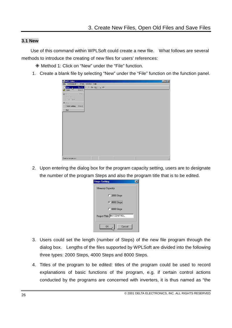
3.1 New
Use of this command within WPLSoft could create a new file. What follows are several methods to introduce the creating of new files for users’ references:
Method 1: Click on “New” under the “File” function. 1. Create a blank file by selecting “New” under the “File” function on the function panel.
2. Upon entering the dialog box for the program capacity setting, users are to designate the number of the program Steps and also the program title that is to be edited.
3. Users could set the length (number of Steps) of the new file program through the dialog box. Lengths of the files supported by WPLSoft are divided into the following three types: 2000 Steps, 4000 Steps and 8000 Steps.
4. Titles of the program to be edited: titles of the program could be used to record explanations of basic functions of the program, e.g. if certain control actions conducted by the programs are concerned with inverters, it is thus named as “the

3. Create New Files, Open Old Files and Save Files
© 2001 DELTA ELECTRONICS, INC. ALL RIGHTS RESERVED 27
Inverter Control”.
5. WPLSoft has designated in advance the type of document it produced as “* .dvp”, and will set beforehand the currently created filename as dvp0.dvp. (When new files are created, the system will check automatically whether there are pre-set filenames such as dvp0.dvp, dvp1.dvp, etc., in the operation catalogue; if the answer is “Yes”, the next number followed will be set as the pre-set filename).
The following diagram is the image of the currently created file.
Method 2: Click on the icon, , on the general tool bar to create a new file.
Method 3: Make use of the speedy key-in function, and simply type in the compound buttons〔Ctrl〕+〔N〕, to create a new file.
3.2 Open
Whether the PLC program is designed through the DPLSoft (for DOS) editor or the WPLSoft (for Windows) editor, it could be open and loaded interchangeably between these two; use of this editor could open the existed PLC programs (within the hard drive) in the window. WPLSoft utilizes the project-by-project conducts, and could thus only open one file at one time, and users could then choose filenames of his/her own desired file under the “Open” dialog box. If users want to edit two PLC programs at the same time, simply execute the WPLSoft editor repeatedly to conduct functions such as mutual editing, copying, cutting

3. Create New Files, Open Old Files and Save Files
© 2001 DELTA ELECTRONICS, INC. ALL RIGHTS RESERVED 28
and pasting. When this command is used within WPLSoft to open old files, several ways are presented to open the old files:
Method 1: Click on “Open” under the “File” function. 1. Click on “Open” under the “File” function to open old documents in the hard drive.
2. The “Open” Dialog Box:
The following selections allow users to designate any old files that he/she wishes to open:
Filename Key in or select the filename of your desire; this list includes all the files’ designated sub-filenames within the “File Name” block in detail. File Type Select the file type that is to be open: IL File (which is *.dvp). Location Search Choose the hard drive and the folder in which the *.dvp file of your interest is located.
Method 2: Click on the icon, , on the general tool bar to open old files in the hard

3. Create New Files, Open Old Files and Save Files
© 2001 DELTA ELECTRONICS, INC. ALL RIGHTS RESERVED 29
drive. Method 3: Make use of the speedy key-in function, and simply type in the compound
buttons〔Ctrl〕+〔O〕, to open old files in the hard drive.
3.3 Save
Use of this command within WPLSoft will enable the program to be saved with its original filename into the current folder in the hard drive. What follows are some methods to save the files:
Method 1: Click on “Save” under the “File” function; this file will thus be saved with its original filename.
Method 2: Make use of the speedy key-in function, and simply type in the compound buttons〔Ctrl〕+〔S〕, to save the file with its original filename.
3.4 Save As…
Use of this command within WPLSoft will have the program saved into the hard drive with a new name given by users. When this new document is save d for the first time, WPLSoft will name this file with a pre-set filename; if users want to change the filename or the folder name before saving the file, click on the “Save As….” command. What follows are some method to save new files with new names:
Method 1: Click on “Save as” under the “File” function. Select “Save as” under the “File” function on the function panel.
Then key in the new filename and have the file saved.

3. Create New Files, Open Old Files and Save Files
© 2001 DELTA ELECTRONICS, INC. ALL RIGHTS RESERVED 30
Method 2: Click on the icon, , on the general tool bar to save the file into the hard drive with a new name given by users.
4. The Ladder Diagram Editing Mode
© 2001 DELTA ELECTRONICS, INC. ALL RIGHTS RESERVED 31
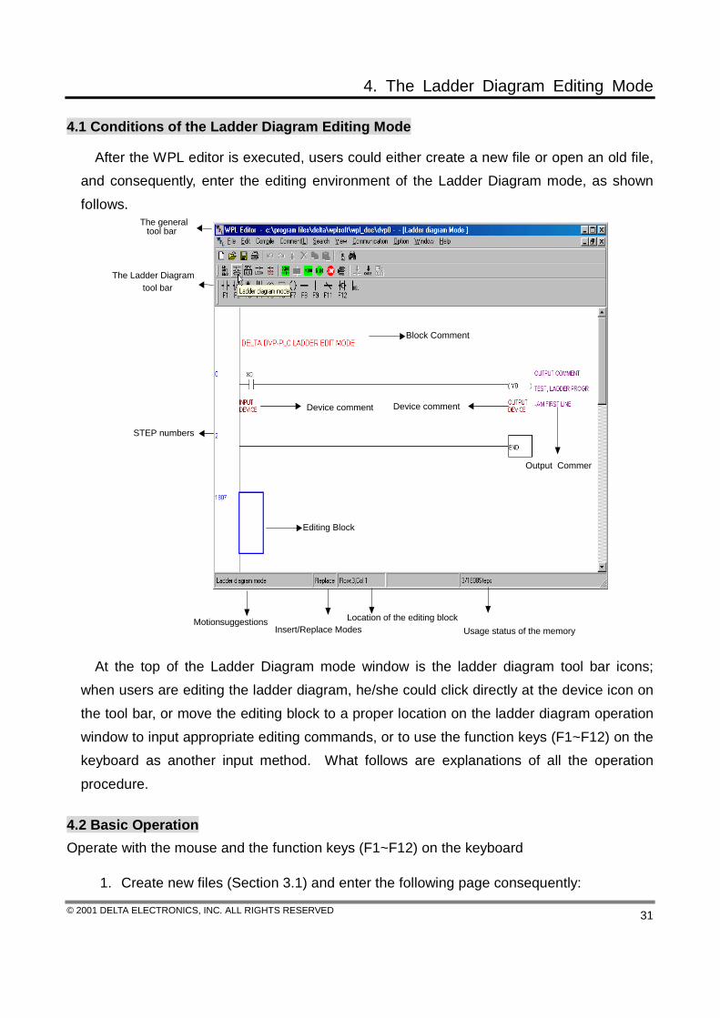
4.1 Conditions of the Ladder Diagram Editing Mode
After the WPL editor is executed, users could either create a new file or open an old file, and consequently, enter the editing environment of the Ladder Diagram mode, as shown follows.
Editing Block
Block Comment
Output Commen
Device comment
STEP numbers
Motion suggestionsInsert/Replace Modes
Location of the editing blockUsage status of the memory
The Ladder Diagram tool bar
The general tool bar
Device comment
At the top of the Ladder Diagram mode window is the ladder diagram tool bar icons;
when users are editing the ladder diagram, he/she could click directly at the device icon on the tool bar, or move the editing block to a proper location on the ladder diagram operation window to input appropriate editing commands, or to use the function keys (F1~F12) on the keyboard as another input method. What follows are explanations of all the operation procedure.
4.2 Basic Operation Operate with the mouse and the function keys (F1~F12) on the keyboard
1. Create new files (Section 3.1) and enter the following page consequently:

4. The Ladder Diagram Editing Mode
© 2001 DELTA ELECTRONICS, INC. ALL RIGHTS RESERVED 32
Enlarge Wondows
2. Click on the “Normally Open” icon, , or press the F1 function key:
3. What appears consequently are the device name and the comment dialog box,
simply select a proper device name, device number and the comment, then press “OK” to complete the process.
4. The Ladder Diagram Editing Mode
© 2001 DELTA ELECTRONICS, INC. ALL RIGHTS RESERVED 33
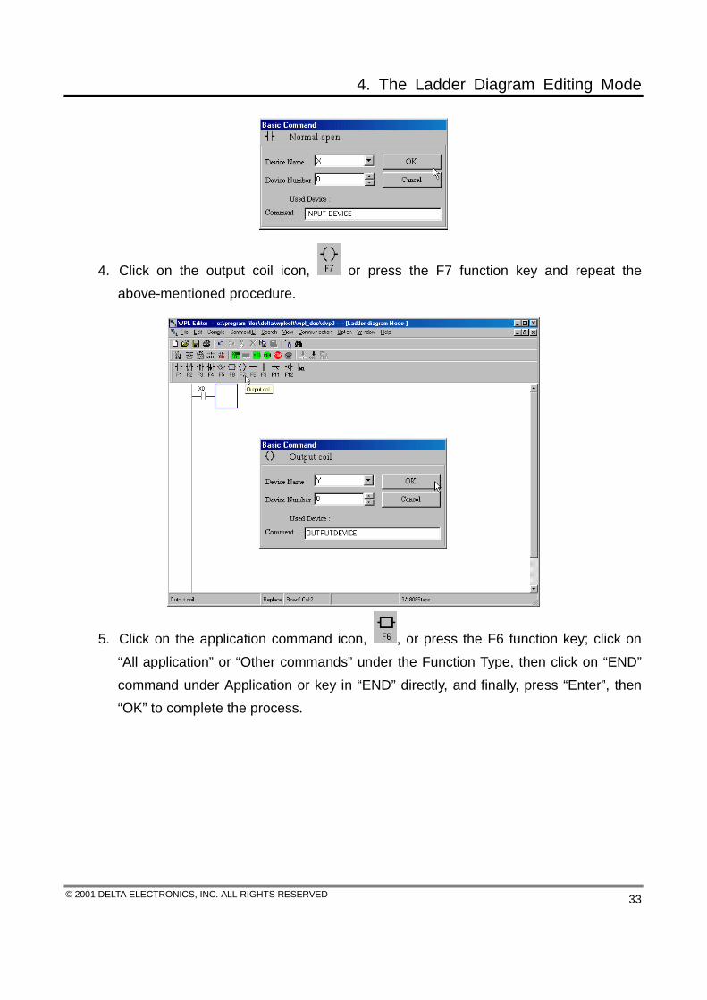
4. Click on the output coil icon, or press the F7 function key and repeat the above-mentioned procedure.
5. Click on the application command icon, , or press the F6 function key; click on “All application” or “Other commands” under the Function Type, then click on “END” command under Application or key in “END” directly, and finally, press “Enter”, then “OK” to complete the process.

4. The Ladder Diagram Editing Mode
© 2001 DELTA ELECTRONICS, INC. ALL RIGHTS RESERVED 34
6. Click on the icon, and convert the edited ladder diagram into the command program through compiling, and after the compiling is completed, the number of Steps will show up on the left side of the Origin.
7. If the graph of the ladder diagram appeared to be incorrect, the message dialog box would show up and point out the exact erroneous rows.

4. The Ladder Diagram Editing Mode
© 2001 DELTA ELECTRONICS, INC. ALL RIGHTS RESERVED 35
Keyboard Operation
1. Place the editing block at the beginning of the document, key in LD X10 through the keyboard and press “Enter”, or click on “OK” for completion.
2. Key in OUT Y10→press “Enter”, then key in END through the keyboard→Enter, then click on the icon to compile the edited ladder diagram.
4. The Ladder Diagram Editing Mode
© 2001 DELTA ELECTRONICS, INC. ALL RIGHTS RESERVED 36
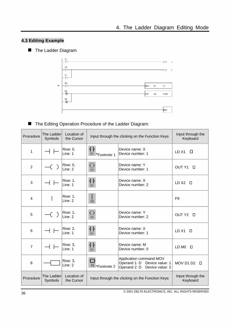
4.3 Editing Example
The Ladder Diagram
The Editing Operation Procedure of the Ladder Diagram:
Procedure The Ladder Symbols
Location of the Cursor Input through the clicking on the Function Keys Input through the
Keyboard
1 Row: 0, Line: 1 *Footnote 1
Device name: X Device number: 1 LD X1 ↵↵↵↵
2 Row: 0, Line: 2
Device name: Y Device number: 1 OUT Y1 ↵↵↵↵
3 Row: 1, Line: 1
Device name: X Device number: 2 LD X2 ↵↵↵↵
4 Row: 1, Line: 2
F9
5 Row: 1, Line: 2
Device name: Y Device number: 2 OUT Y2 ↵↵↵↵
6 Row: 2, Line: 1
Device name: X Device number: 1 LD X1 ↵↵↵↵
7 Row: 3, Line: 1
Device name: M Device number: 0 LD M0 ↵↵↵↵
8 Row: 3, Line: 2 *Footnote 2
Application command MOV Operand 1: D Device value: 1 Operand 2: D Device value: 2
MOV D1 D2 ↵↵↵↵
Procedure The Ladder Symbols
Location of the Cursor Input through the clicking on the Function Keys Input through the
Keyboard

4. The Ladder Diagram Editing Mode
© 2001 DELTA ELECTRONICS, INC. ALL RIGHTS RESERVED 37
9 Row: 4, Line: 0 Double click the mouse to input P0 P0 ↵↵↵↵
10 Row: 4, Line: 1
Device name: M Device number: 1 LDP M1 ↵↵↵↵
11 Row: 4, Line: 2
F9
12 Row: 4, Line: 2
Counting command CNT Operand 1: C Device value: 0 Operand 2: K Device value: 100
CNT C0 K100 ↵↵↵↵
13 Row: 5, Line: 1
Device name: M Device number: 1 LDF M1 ↵↵↵↵
14 Row: 6, Line: 1
Application command END END ↵↵↵↵
After the input is completed, the Ladder Diagram could be converted to the command code and the SFC diagram through compiling, and will look like what follows:
*Footnote 1: Basic command input
4. The Ladder Diagram Editing Mode
© 2001 DELTA ELECTRONICS, INC. ALL RIGHTS RESERVED 38
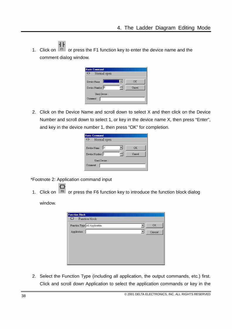
1. Click on or press the F1 function key to enter the device name and the comment dialog window.
2. Click on the Device Name and scroll down to select X and then click on the Device Number and scroll down to select 1, or key in the device name X, then press “Enter”, and key in the device number 1, then press “OK” for completion.
*Footnote 2: Application command input
1. Click on or press the F6 function key to introduce the function block dialog
window.
2. Select the Function Type (including all application, the output commands, etc.) first. Click and scroll down Application to select the application commands or key in the

4. The Ladder Diagram Editing Mode
© 2001 DELTA ELECTRONICS, INC. ALL RIGHTS RESERVED 39
command name directly within Application through the keyboard, afterwards, press “Enter” for completion.
3. Select “Transmission Comparison Command” under the Function Type, and key in the “MOV” command into Application and press “OK” for completion. (Or scroll down Application to select the “MOV” command). The Function Block Dialog Window will be shown as follows:
4. Input operands 1, 2 and other device values in order. If the index exists, click on E or F, if not, simply skip this procedure; press “OK” for completion if the setup is done, as shown on the above diagram. In addition, users could also select directly the parameters under the function block or to click on devices with “*” affixed within the Device reference chart, to serve as another mean for the input method.
4.4 Auxiliary Editing
Insert/Replace Mode
Use the 〔Insert〕 key to switch to the Insert Mode or the Replace Mode when editing. � If the status panel is displayed as the Replace Mode, press the 〔Insert〕 key to switch
the editing to the Insert Mode. Insert the ladder symbol to where the editing block locates, and other ladder symbols that followed would shift one space behind.
� If the status panel is displayed as the Insert Mode, press the 〔Insert〕 key to switch the editing to the Replace Mode. Insert the ladder symbol to replace the original ladder symbol from where the editing block locates, and the location of all the ladder symbols that followed would not be altered.
4. The Ladder Diagram Editing Mode
© 2001 DELTA ELECTRONICS, INC. ALL RIGHTS RESERVED 40
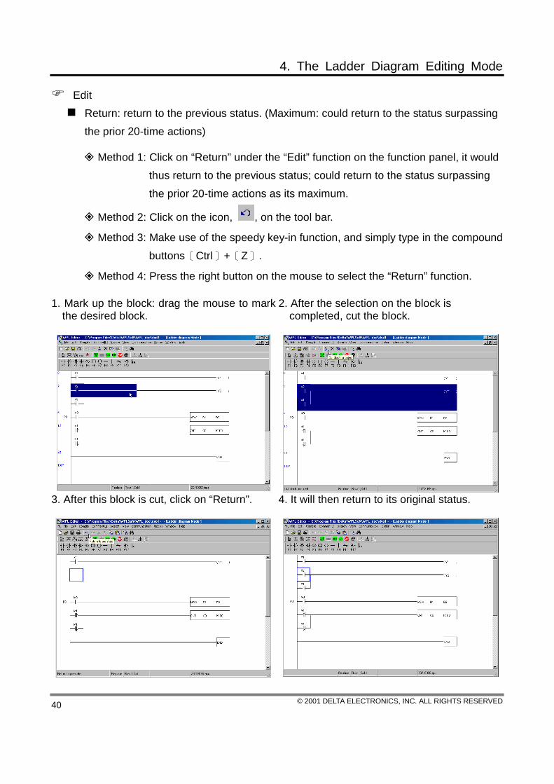
Edit Return: return to the previous status. (Maximum: could return to the status surpassing the prior 20-time actions)
Method 1: Click on “Return” under the “Edit” function on the function panel, it would thus return to the previous status; could return to the status surpassing the prior 20-time actions as its maximum.
Method 2: Click on the icon, , on the tool bar.
Method 3: Make use of the speedy key-in function, and simply type in the compound buttons〔Ctrl〕+〔Z〕.
Method 4: Press the right button on the mouse to select the “Return” function.
1. Mark up the block: drag the mouse to mark the desired block.
2. After the selection on the block is completed, cut the block.
3. After this block is cut, click on “Return”.
4. It will then return to its original status.
4. The Ladder Diagram Editing Mode
© 2001 DELTA ELECTRONICS, INC. ALL RIGHTS RESERVED 41
Redo: redo the previous action. Method 1: Click on “Redo” under the “Edit” function: (1) if the selection on “Return”
is possible, click on return to go back to its previous status; (2) if the selection on “Return” is not available, redo the previous action again (e.g. command input, block paste).
Method 2: Click on the icon, , on the tool bar.
Method 3: Make use of the speedy key-in function, and simply type in the compound buttons〔Ctrl〕+〔W〕.
Method 4: Press the right button on the mouse to select the “Redo” function.
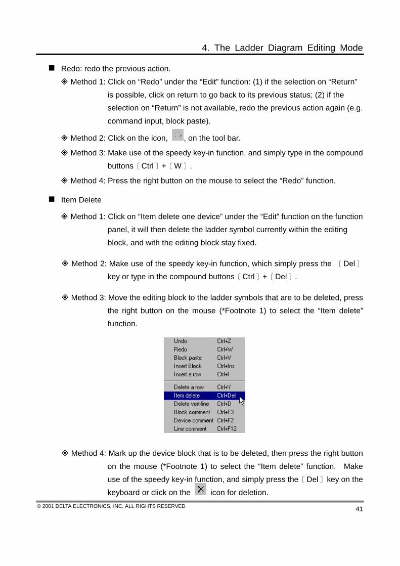
Item Delete
Method 1: Click on “Item delete one device” under the “Edit” function on the function panel, it will then delete the ladder symbol currently within the editing block, and with the editing block stay fixed.
Method 2: Make use of the speedy key-in function, which simply press the 〔Del〕 key or type in the compound buttons〔Ctrl〕+〔Del〕.
Method 3: Move the editing block to the ladder symbols that are to be deleted, press the right button on the mouse (*Footnote 1) to select the “Item delete” function.
Method 4: Mark up the device block that is to be deleted, then press the right button on the mouse (*Footnote 1) to select the “Item delete” function. Make use of the speedy key-in function, and simply press the 〔Del〕 key on the keyboard or click on the icon for deletion.

4. The Ladder Diagram Editing Mode
© 2001 DELTA ELECTRONICS, INC. ALL RIGHTS RESERVED 42
*Footnote 1: When the ladder diagram is undergoing the editing process, there are certain differences in between the display of pressing the right button on the mouse (as shown in the diagram of Method 3) during the editing block’s operation and the display of pressing the right button on the mouse (as shown in the diagram of Method 4) during the block markup.
Delete a row Method 1: Click on “Delete a row” under the “Edit” function on the function panel, it
will then delete this row currently within the editing block, and the ladder diagram that followed would combine with the ladder diagram remained.
Method 2: Make use of the speedy key-in function, and simply type in the compound buttons〔Ctrl〕+〔Y〕.
Method 3: Move the editing block to the row that is to be deleted, and press the right button on the mouse to select the “Delete a row” function.
Method 4: Block mark the whole row that is to be deleted, and press the right button on the mouse to select the “Block delete” function, then make use of the speedy key-in function to press the 〔Del〕 key or simply click on the icon.
4. The Ladder Diagram Editing Mode
© 2001 DELTA ELECTRONICS, INC. ALL RIGHTS RESERVED 43
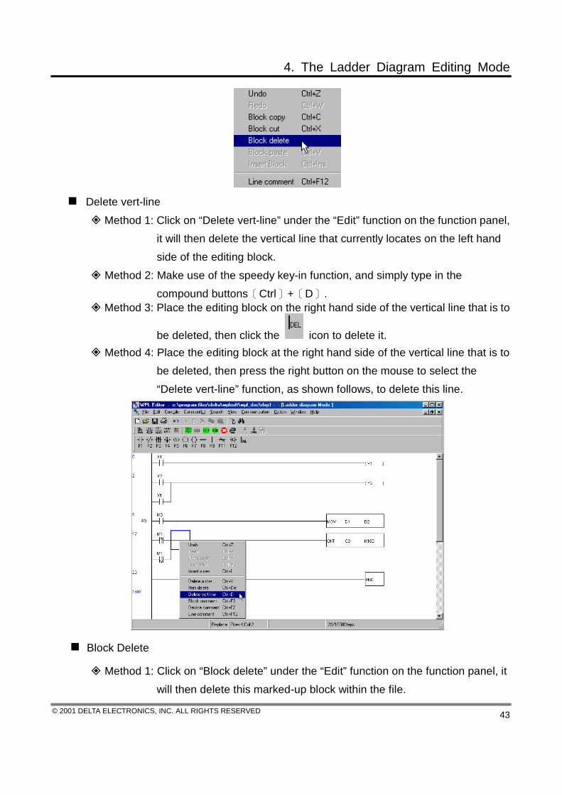
Delete vert-line
Method 1: Click on “Delete vert-line” under the “Edit” function on the function panel, it will then delete the vertical line that currently locates on the left hand side of the editing block.
Method 2: Make use of the speedy key-in function, and simply type in the compound buttons〔Ctrl〕+〔D〕.
Method 3: Place the editing block on the right hand side of the vertical line that is to
be deleted, then click the icon to delete it. Method 4: Place the editing block at the right hand side of the vertical line that is to
be deleted, then press the right button on the mouse to select the “Delete vert-line” function, as shown follows, to delete this line.
Block Delete
Method 1: Click on “Block delete” under the “Edit” function on the function panel, it will then delete this marked-up block within the file.
4. The Ladder Diagram Editing Mode
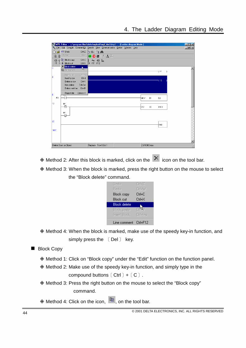
© 2001 DELTA ELECTRONICS, INC. ALL RIGHTS RESERVED 44
Method 2: After this block is marked, click on the icon on the tool bar.
Method 3: When the block is marked, press the right button on the mouse to select the “Block delete” command.
Method 4: When the block is marked, make use of the speedy key-in function, and
simply press the 〔Del〕 key.
Block Copy
Method 1: Click on “Block copy” under the “Edit” function on the function panel. Method 2: Make use of the speedy key-in function, and simply type in the
compound buttons〔Ctrl〕+〔C〕. Method 3: Press the right button on the mouse to select the “Block copy”
command.
Method 4: Click on the icon, , on the tool bar.

4. The Ladder Diagram Editing Mode
© 2001 DELTA ELECTRONICS, INC. ALL RIGHTS RESERVED 45
Block Cut Method 1: Click on “Block cut” under the “Edit” function on the function panel.
Method 2: Click on the icon, , on the tool bar.
Method 3: Make use of the speedy key-in function, and simply type in the compound buttons〔Ctrl〕+〔X〕.
Method 4: Press the right button on the mouse to select the “Block cut” command.

4. The Ladder Diagram Editing Mode
© 2001 DELTA ELECTRONICS, INC. ALL RIGHTS RESERVED 46
Block Paste Method 1: Click on “Block paste” under the “Edit” function on the function panel.
Method 2: Click on the icon, , on the tool bar.
Method 3: Make use of the speedy key-in function, and simply type in the compound buttons〔Ctrl〕+〔V〕.
Method 4: Press the right button on the mouse to select the Block paste” command.
Insert Block Method 1: Click on “Insert block” under the “Edit” function on the function panel.
Method 2: Make use of the speedy key-in function, and simply type in the

4. The Ladder Diagram Editing Mode
© 2001 DELTA ELECTRONICS, INC. ALL RIGHTS RESERVED 47
compound buttons〔Ctrl〕+〔Ins〕. Method 3: Press the right button on the mouse to select the “Insert block”
command.
Compile This function is used to compile current PLC programs. If the editing of the ladder
diagram is completed during the ladder diagram mode, execution of this function will check whether the ladder diagram is valid or not, and if the conversion is correct, the ladder diagram would thus be converted to the command program or the SFC diagram. And at the same time, on the left-hand side of the Origin within the ladder-diagram editing zone, there will appear the ladder diagram in which every block is relative to the address (STEP) of the program memory. If error occurred, WPLSoft will send out messages indicating the erroneous line and displaying the error code (please refer to the DVP-PLC User Manual).
If the editing is completed during the command mode, execution of this function will start checking whether the conversion is correct or not; if the conversion is correct, the command program will be converted to the ladder diagram. If error occurred, WPLSoft will send out messages indicating the erroneous line and displaying the error code (please refer to the DVP-PLC User Manual).
Error message displayed at the Ladder Diagram Mode:
Error message displayed at the Command Mode:

4. The Ladder Diagram Editing Mode
© 2001 DELTA ELECTRONICS, INC. ALL RIGHTS RESERVED 48
Ladder Diagram --〉Instruction
Method 1: Click on “Ladder Diagram --〉Instruction” under the “Compile” function on the function panel.
Method 2: Click on the icon.
Method 3: Key in the compound buttons〔Ctrl〕+〔F10〕.
Instruction --〉Ladder Diagram
Method 1: Click on “Instruction --〉Ladder Diagram” under the “Compile” function on the function panel.
Method 2: Click on the icon.
Method 3: Key in the compound buttons〔Ctrl〕+〔F11〕.
SFC --〉Instruction
Method 1: Click on “SFC --〉Instruction” under the “Compile” function on the function panel.
Method 2: Click on the icon.
Method 3: Key in the compound buttons〔Ctrl〕+〔F11〕.
Double Loop Check Check the devices’ repetitive usages on the OUT, SET, RST, TMR, CNT and DCNT
commands. Click on “Double loop check” under the “Compile” function on the function panel,

4. The Ladder Diagram Editing Mode
© 2001 DELTA ELECTRONICS, INC. ALL RIGHTS RESERVED 49
there will appear a coil repeat check dialog window, simply check those commands that are to be examined and press “OK”; if the double loop does exist within the circuit program, it will be indicated in the output window.
The printing method of the PLC program contains “Print-all” and “Print-part” for users, and it is ready for print out if the description on the dialog window is followed.
1. Click on “Print ladder diagram” under the “File” function on the function panel or click on the icon, it will then show the “Print Type Setting” dialog window (as shown follows) for users’ selection on setting up the print operation, ratio, type (all or part), print color (if it is not a color printer, choose the black-and-white printer to get a better print definition), the title of the program to be edited, and the print preview, etc.
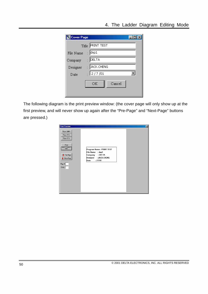
2. For the above diagram, when clicking on “Cover Page”, it will appear instantly the dialog window for the cover page setup, and users could key in any relevant information as needed, as shown follows.
4. The Ladder Diagram Editing Mode
© 2001 DELTA ELECTRONICS, INC. ALL RIGHTS RESERVED 50
The following diagram is the print preview window: (the cover page will only show up at the first preview, and will never show up again after the “Pre-Page” and “Next-Page” buttons are pressed.)

4. The Ladder Diagram Editing Mode
© 2001 DELTA ELECTRONICS, INC. ALL RIGHTS RESERVED 51
Search
Jump Use of this command could designate a Step for the program to jump to, and if the
designated Step does not exist, the program will jump to the nearest Step and place the Step in the first line.
Method 1: Click on “Jump” under the “Search” function on the function panel.
Method 2: Click on the icon.
Method 3: Key in the compound buttons〔Ctrl〕+〔F〕.
Search/Replace
Use of this command would display an input dialog box within the program, and users could thus key in a device name that is to be searched (if only the “Search” action is conducted, simply key in the to-be-searched device name to the dialog box), and could also select the “Search” type. Moreover, it could replace all or part of the device names (key in the to-be-replaced device name into the “Device Search” device name dialog box, and the to-replace device name into the “Device Replace” device name dialog box); only selections of the same type could be replaced. Since the ladder diagram mode is different from the command mode, it will be displayed in different dialog boxes.

4. The Ladder Diagram Editing Mode
© 2001 DELTA ELECTRONICS, INC. ALL RIGHTS RESERVED 52
Method 1: Click on “Search/Replace” under the “Search” function on the function panel.
階梯圖模式 指令模式
Method 2: Click on the icon.
Method 3: Key in the compound buttons〔Ctrl〕+〔R〕.
Restrictive Conditions
Only devices of the same type could be replaced, e.g. if D1 is replaced by D11, it is thus viewed as successful, but if it is replaced by C100, it is then a failure.
Home – jump directly to the start of the program Method 1: Click on “Home” under the “Search” function on the function panel.
Method 2: Key in the compound buttons〔Ctrl〕+〔Home〕.
END – jump directly to the very last line of the program
Method 1: Click on “END” under the “Search” function on the function panel.
Method 2: Key in the compound buttons〔Ctrl〕+〔End〕.
Search – search for the location of the application command within the program
Method: Click on “search” under the “Search” function on the function panel.
Copy the Ladder Diagrams among Files If two or more than two PLC programs are to be edited at the same time, simply open two
or more than two WPLSofts (execute WPLSoft for two or more than two times), and it could then proceed with each individual program-editing within each respective WPL editor window.
Function of the copy among files could be distinguished as the ladder diagram mode or the command mode (please refer to Section 5.3). Block copied under the first WPL editor of the ladder diagram mode could only be pasted when the focus is switched to another WPL editor of the ladder diagram mode, however, if the focus is switched to the WPL editor of the command mode, action of block pasting will not be displayed since the editing method is

4. The Ladder Diagram Editing Mode
© 2001 DELTA ELECTRONICS, INC. ALL RIGHTS RESERVED 53
different.
1. Block copy under the first WPL editor of the Ladder Diagram Mode.
2. Block paste under the second WPL editor of the Ladder Diagram Mode.
4. The Ladder Diagram Editing Mode
© 2001 DELTA ELECTRONICS, INC. ALL RIGHTS RESERVED 54
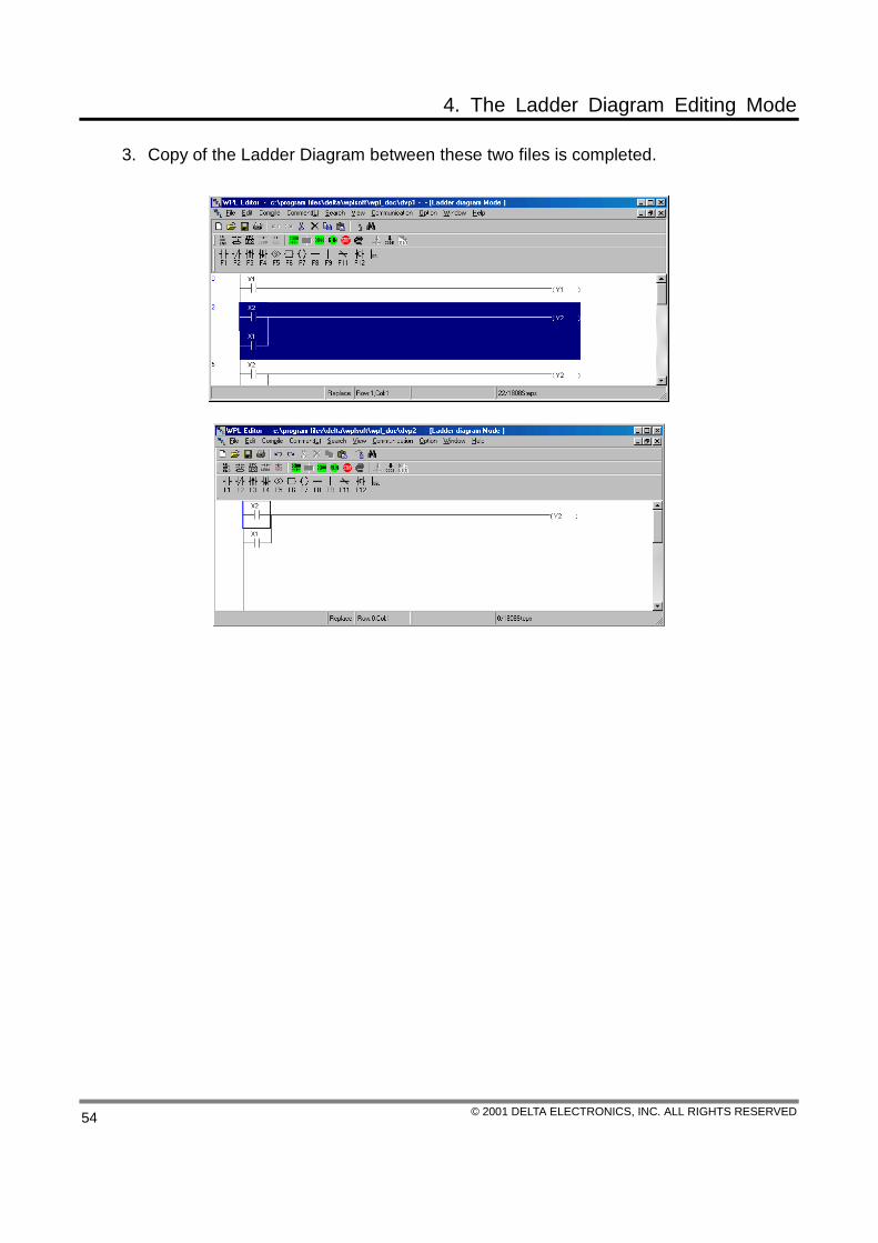
3. Copy of the Ladder Diagram between these two files is completed.

5. The Command Editing Mode
© 2001 DELTA ELECTRONICS, INC. ALL RIGHTS RESERVED 55
WPLSoft provides two types of editing modes for the PLC language, one is the program language for the Ladder Diagram Mode (please refer to Chapter 4 for the editing method), the other is the program language for the Command Mode; both programs could be converted interchangeably between each other through compiling.
5.1 Conditions of the Command Editing Mode
Display of the editing mode
STEP numbers
Device labelling message
Editing location prompt
Instruct edit area
Insert/Replace Modes
5.2 Basic Operation
We are to introduce various techniques (include functions such as Delete, Insert, Block Copy and Replace) that are relevant to the input-editing commands of WPLSoft.
Input the PLC commands
After entering the command editing mode, key in the PLC command directly, if the format of the command is valid, press 〔Enter〕 for completion. The commands will thus locate at the editing zone, and on the left-hand side will be the program memory address of the command within the PLC MPU, which users could view clearly the relative address of the

5. The Command Editing Mode
© 2001 DELTA ELECTRONICS, INC. ALL RIGHTS RESERVED 56
command within the program memory. Please refer to the PLC MPU User Manual for formats of all the commands.
Enter the Command Editing Mode:
1. After WPL is executed and new files are created (click on ), click on “Instruction Mode” (as shown follows) under the “View” function or click on the icon or type in the compound buttons〔Ctrl〕+〔Alt〕+〔I〕.
2. Input the program at the highlighted editing site.
Example of the input operation
Command program…according to the following programs
〈0000〉 LD X1 〈0001〉 OR M0 〈0002〉 OUT Y1 〈0003〉 MOV D1 D2 〈0008〉 OUT Y2 〈0009〉 END
After the input is completed, it could be converted to the Ladder Diagram and the SFC
Diagram through compiling, as shown follows.

5. The Command Editing Mode
© 2001 DELTA ELECTRONICS, INC. ALL RIGHTS RESERVED 57
Whether it is of the ladder diagram mode, the command mode or of the SFC editing mode, once the program is edited or revised, be sure to go through the compiling (please refer to Section 4.4) before writing in to the PLC MPU.
5.3 Auxiliary Editing
Insert/Replace Mode
Use the 〔Insert〕 key to switch in between the Insert Mode or the Replace Mode when editing. If the status panel is displayed as the Replace Mode, simply press 〔Insert〕 key to switch to the Insert Mode:
1. Enter the Insert Mode, and if the following program has already shown:
5. The Command Editing Mode
© 2001 DELTA ELECTRONICS, INC. ALL RIGHTS RESERVED 58
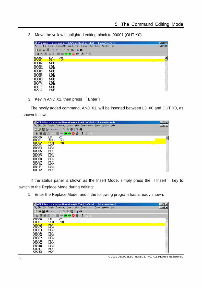
2. Move the yellow highlighted editing block to 00001 (OUT Y0).
3. Key in AND X1, then press 〔Enter〕.
The newly added command, AND X1, will be inserted between LD X0 and OUT Y0, as shown follows.
If the status panel is shown as the Insert Mode, simply press the 〔Insert〕 key to switch to the Replace Mode during editing:
1. Enter the Replace Mode, and if the following program has already shown:

5. The Command Editing Mode
© 2001 DELTA ELECTRONICS, INC. ALL RIGHTS RESERVED 59
2. Move the yellow highlighted editing block to 00001 (OUT Y0).
3. Key in AND X1, then press 〔Enter〕.
The newly added command, AND X1, will replace OUT Y0, as shown follows.
Editing
Return: return to the previous status. (Maximum: could return to the status surpassing the prior 20-time actions)
Method 1: Click on “Return” under the “Edit” function on the function panel.
Method 2: Click on the icon, , on the tool bar. Method 3: Make use of the speedy key-in function, which is to type in the
compound buttons〔Ctrl〕+〔Z〕.
Method 4: Press the right button on the mouse to select the “Return” function.

5. The Command Editing Mode
© 2001 DELTA ELECTRONICS, INC. ALL RIGHTS RESERVED 60
1. Mark up the block: drag the mouse to mark the desired block.
2. After the selection on the block is completed, delete the block.
3. After this block is deleted, the whole
program will be indented, simply click on “Return”.
4. It will then return to its original status.
Redo: redo the motion prior to “Return”. Method 1: Click on “Redo” under the “Edit” function: (1) if the selection on “Return”
is possible, click on return to go back to its previous status; (2) if the selection on “Return” is not available, redo the previous action again (e.g. command input, block paste).
Method 2: Click on the icon, , on the tool bar. Method 3: Make use of the speedy key-in function, and simply type in the
compound buttons〔Ctrl〕+〔W〕.
Method 4: Press the right button on the mouse to select the “Redo” function.
5. The Command Editing Mode
© 2001 DELTA ELECTRONICS, INC. ALL RIGHTS RESERVED 61
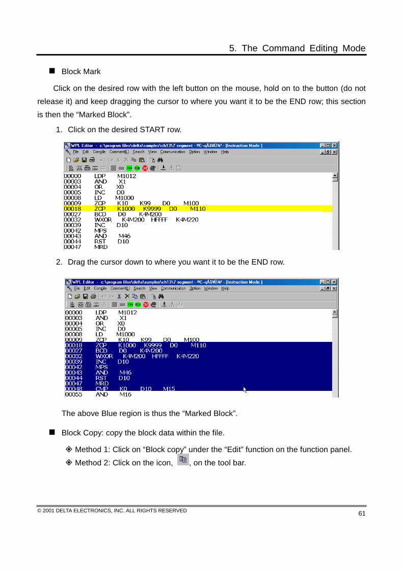
Block Mark
Click on the desired row with the left button on the mouse, hold on to the button (do not release it) and keep dragging the cursor to where you want it to be the END row; this section is then the “Marked Block”.
1. Click on the desired START row.
2. Drag the cursor down to where you want it to be the END row.
The above Blue region is thus the “Marked Block”.
Block Copy: copy the block data within the file.
Method 1: Click on “Block copy” under the “Edit” function on the function panel. Method 2: Click on the icon, , on the tool bar.

5. The Command Editing Mode
© 2001 DELTA ELECTRONICS, INC. ALL RIGHTS RESERVED 62
Method 3: Make use of the speedy key-in function, and simply type in the compound buttons〔Ctrl〕+〔C〕.
Method 4: Press the right button on the mouse to select the “Block copy” command.
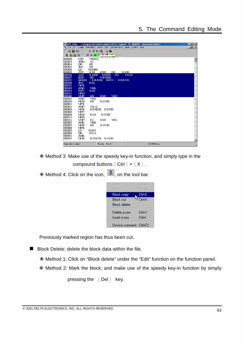
Block Cut: cut the block data within the file.
Method 1: Click on “Block cut” under the “Edit” function on the function panel. Method 2: Press the right button on the mouse to select the “Block cut” command.
5. The Command Editing Mode
© 2001 DELTA ELECTRONICS, INC. ALL RIGHTS RESERVED 63
Method 3: Make use of the speedy key-in function, and simply type in the compound buttons〔Ctrl〕+〔X〕.
Method 4: Click on the icon, , on the tool bar.
Previously marked region has thus been cut.
Block Delete: delete the block data within the file.
Method 1: Click on “Block delete” under the “Edit” function on the function panel.
Method 2: Mark the block, and make use of the speedy key-in function by simply
pressing the 〔Del〕 key.

5. The Command Editing Mode
© 2001 DELTA ELECTRONICS, INC. ALL RIGHTS RESERVED 64
Method 3: Mark the block, and press the right button on the mouse to select the “Block delete” command.
Method 4: Mark the block, then simply click on the icon, , on the tool
bar.
Previously marked region has thus been deleted.

5. The Command Editing Mode
© 2001 DELTA ELECTRONICS, INC. ALL RIGHTS RESERVED 65
Block Paste: paste the block data onto the file.
1. Copy the block (refer to the method mentioned earlier) → move the yellow editing highlighted bar to where you want the copied block to be inserted and pasted → click on the icon, and whether it is of the Insert or Replace Mode, it will insert the copied block to where the yellow editing highlighted bar locates and push downward the original contents no matter what.

5. The Command Editing Mode
© 2001 DELTA ELECTRONICS, INC. ALL RIGHTS RESERVED 66
2. Content of the previously marked block will be pasted to 00025.
5. The Command Editing Mode
© 2001 DELTA ELECTRONICS, INC. ALL RIGHTS RESERVED 67
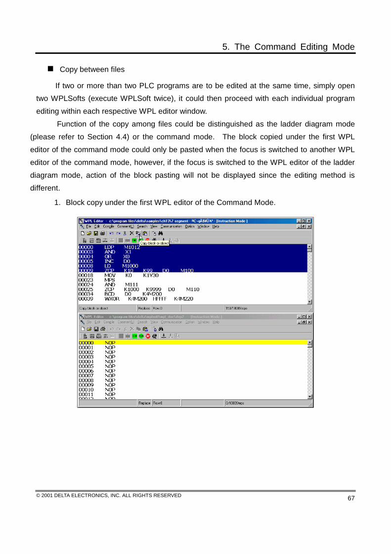
Copy between files
If two or more than two PLC programs are to be edited at the same time, simply open two WPLSofts (execute WPLSoft twice), it could then proceed with each individual program editing within each respective WPL editor window.
Function of the copy among files could be distinguished as the ladder diagram mode (please refer to Section 4.4) or the command mode. The block copied under the first WPL editor of the command mode could only be pasted when the focus is switched to another WPL editor of the command mode, however, if the focus is switched to the WPL editor of the ladder diagram mode, action of the block pasting will not be displayed since the editing method is different.
1. Block copy under the first WPL editor of the Command Mode.
5. The Command Editing Mode
© 2001 DELTA ELECTRONICS, INC. ALL RIGHTS RESERVED 68
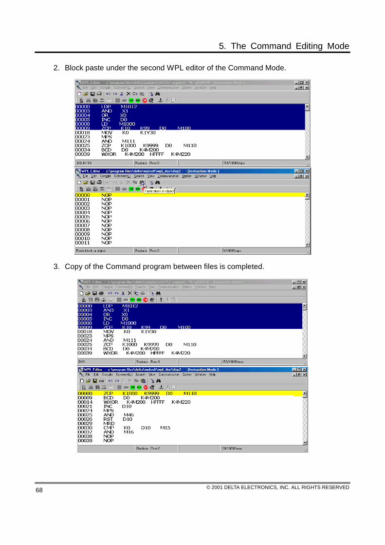
2. Block paste under the second WPL editor of the Command Mode.
3. Copy of the Command program between files is completed.

6. Comment Editing
© 2001 DELTA ELECTRONICS, INC. ALL RIGHTS RESERVED 69
Within the ladder diagram editing mode, the comment editing includes the device comment, the output comment and the block comment, while within the SFC editing mode, only the device comment is included in the comment editing of the command editing mode. We are to introduce them in detail:
Block comment
Device comment
STEP numbers
Motion suggestion
Insert/Replace Modes
Location of the editing block
The usage status of the memo
Ladder Diagram tool bar
General tool bar
Device comment
Output comment
Edit the device comment dialog window: after the input is completed, press [Enter] or the “Save” button to have the record saved.
6. Comment Editing
© 2001 DELTA ELECTRONICS, INC. ALL RIGHTS RESERVED 70
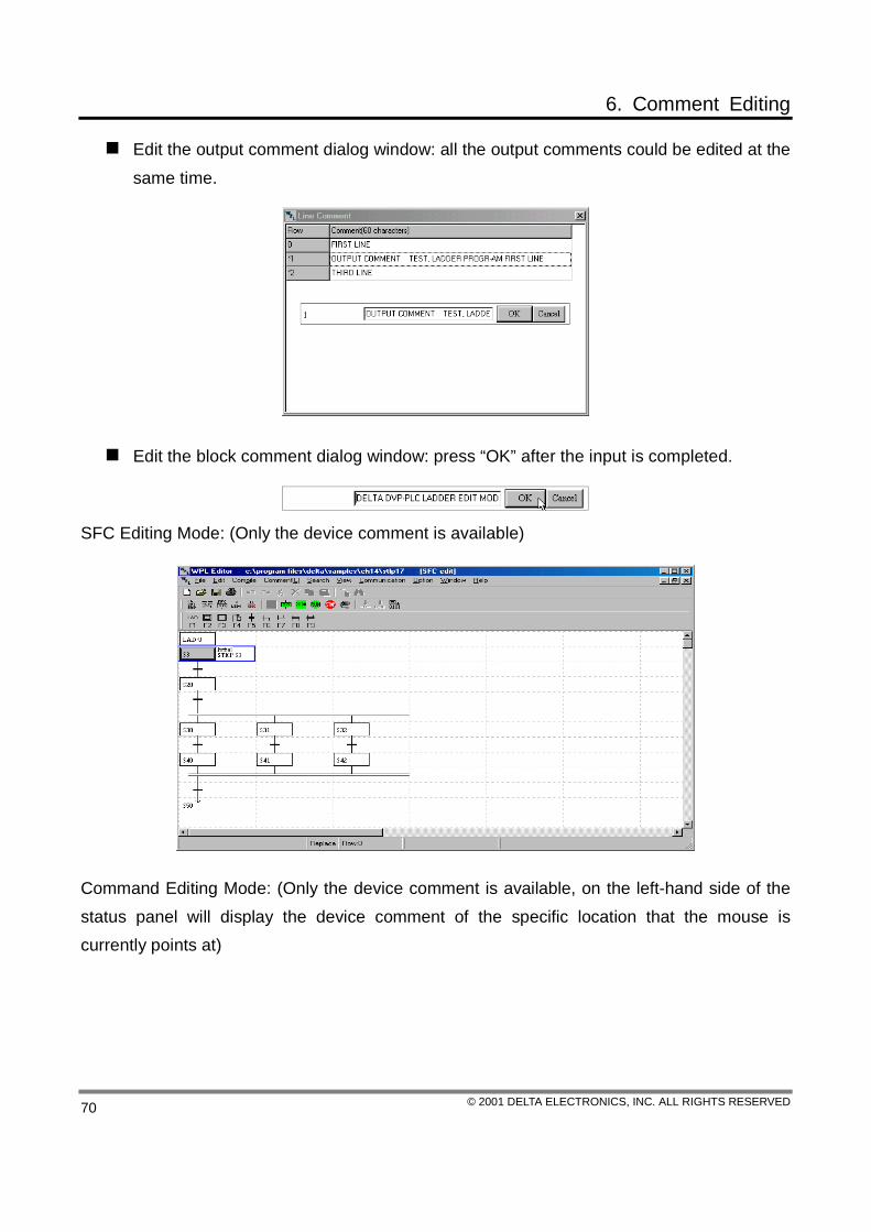
Edit the output comment dialog window: all the output comments could be edited at the same time.
Edit the block comment dialog window: press “OK” after the input is completed.
SFC Editing Mode: (Only the device comment is available)
Command Editing Mode: (Only the device comment is available, on the left-hand side of the status panel will display the device comment of the specific location that the mouse is currently points at)
6. Comment Editing
© 2001 DELTA ELECTRONICS, INC. ALL RIGHTS RESERVED 71
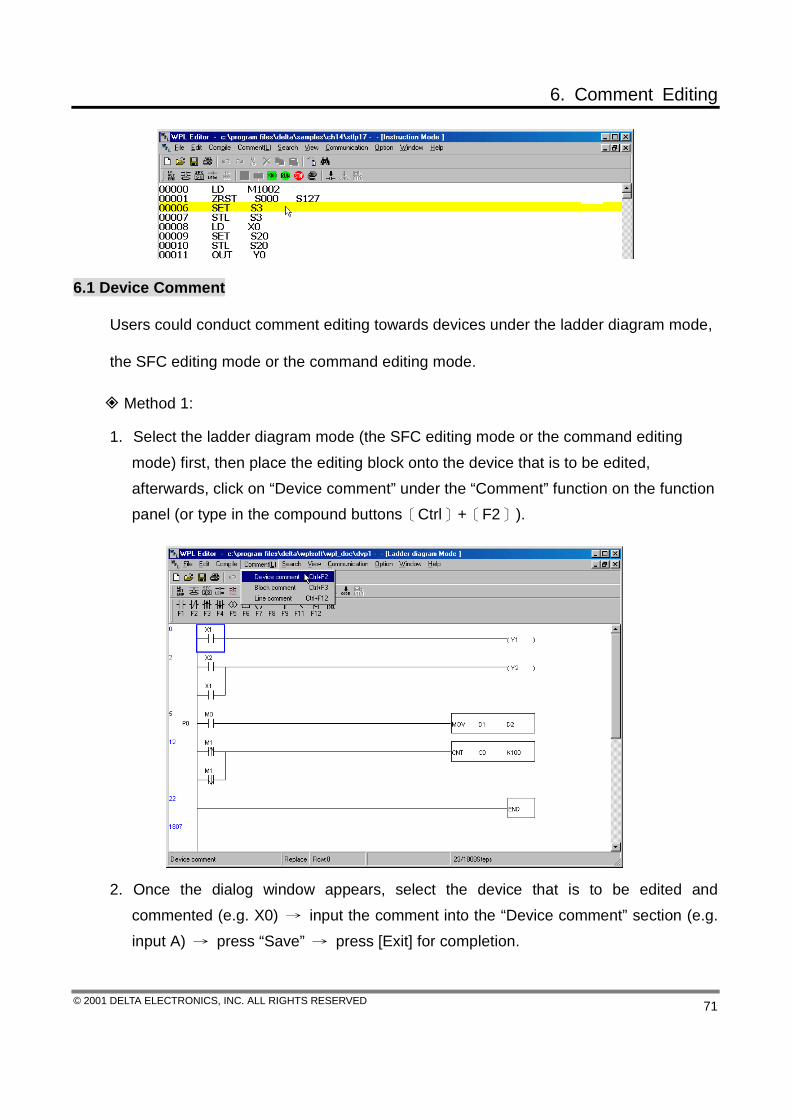
6.1 Device Comment
Users could conduct comment editing towards devices under the ladder diagram mode,
the SFC editing mode or the command editing mode.
Method 1:
1. Select the ladder diagram mode (the SFC editing mode or the command editing mode) first, then place the editing block onto the device that is to be edited, afterwards, click on “Device comment” under the “Comment” function on the function panel (or type in the compound buttons〔Ctrl〕+〔F2〕).
2. Once the dialog window appears, select the device that is to be edited and commented (e.g. X0) → input the comment into the “Device comment” section (e.g. input A) → press “Save” → press [Exit] for completion.

6. Comment Editing
© 2001 DELTA ELECTRONICS, INC. ALL RIGHTS RESERVED 72
3. If comment is to be displayed under the ladder diagram mode, simply click on the
icon, , to switch to comment display, or click on “Device display” under the “View” function on the function panel (or type in the compound buttons〔Ctrl〕+〔Alt〕+〔C〕).
Method 2:
1. Select the ladder diagram mode (the SFC editing mode or the command editing mode) first, then move the editing block to the device that is to be commented (e.g. MOV D1 D2), and press the right button on the mouse to introduce a swift operation frame.
The Ladder Diagram Mode: The SFC Editing Mode: The Command Editing Mode:
6. Comment Editing
© 2001 DELTA ELECTRONICS, INC. ALL RIGHTS RESERVED 73
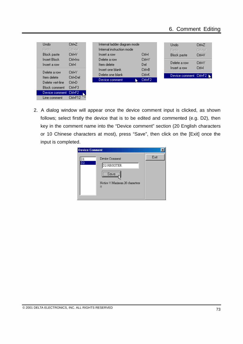
2. A dialog window will appear once the device comment input is clicked, as shown follows; select firstly the device that is to be edited and commented (e.g. D2), then key in the comment name into the “Device comment” section (20 English characters or 10 Chinese characters at most), press “Save”, then click on the [Exit] once the input is completed.

6. Comment Editing
© 2001 DELTA ELECTRONICS, INC. ALL RIGHTS RESERVED 74
Method 3:
1. Select the ladder diagram mode (the SFC editing mode or the command editing mode) first, then place the editing block onto the device that is to be edited, afterwards, click on “View the comment” under the “View” function on the function panel (or type in the compound buttons 〔Ctrl〕+〔Alt〕+〔M〕 or click on the icon).

6. Comment Editing
© 2001 DELTA ELECTRONICS, INC. ALL RIGHTS RESERVED 75
2. Select the device types (e.g. X) under the device comment window.
3. Double click on X2 with the left button on the mouse to introduce the X2 comment input row → key in the comment (e.g. input C), and press “OK” to complete the editing.
6. Comment Editing
© 2001 DELTA ELECTRONICS, INC. ALL RIGHTS RESERVED 76
6.2 Line Comment
Method 1:
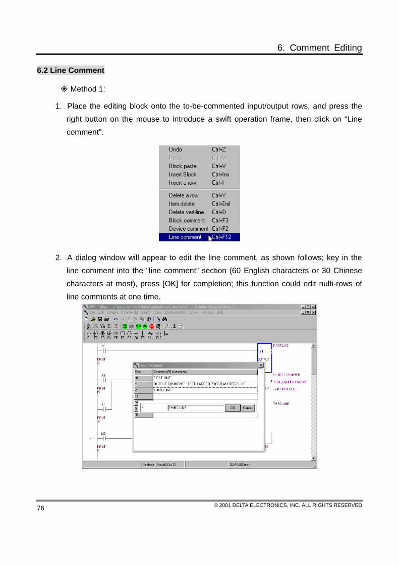
1. Place the editing block onto the to-be-commented input/output rows, and press the right button on the mouse to introduce a swift operation frame, then click on “Line comment”.
2. A dialog window will appear to edit the line comment, as shown follows; key in the line comment into the “line comment” section (60 English characters or 30 Chinese characters at most), press [OK] for completion; this function could edit nulti-rows of line comments at one time.

6. Comment Editing
© 2001 DELTA ELECTRONICS, INC. ALL RIGHTS RESERVED 77
Method 2:
Place the editing block onto the to-be-commented input/output rows, then click on “Line Comment” under the “Comment” function on the function panel (or type in the compound buttons 〔Ctrl〕+〔F12〕), → introduce the “Line Comment” dialog window → key in the Comment (e.g. the 1st row) at the input row under the line comment, press “OK” for completion. At the location that is to be commented, double click the left button on the mouse to introduce the input row under the line comment → key in the comment (e.g. the 2nd row), then press “OK” for completion.

6. Comment Editing
© 2001 DELTA ELECTRONICS, INC. ALL RIGHTS RESERVED 78
6.3 Block Comment
Method 1:
Move the editing block to the blank row (make use of the compound buttons 〔Ctrl〕+〔I〕 to insert new lines) of the to-be-input block comment, and press the right button on the mouse to introduce a swift operation frame, and what appeared next is a dialog window once the block comment is clicked, as shown follows; key in the comment into the “Block comment” section (60 words at most), press [OK] for completion.
Method 2:
Click on “Block comment” under the “Comment” function on the function panel or type in the compound buttons 〔Ctrl〕+〔F3〕 to introduce the block comment input row to edit the block comment.

6. Comment Editing
© 2001 DELTA ELECTRONICS, INC. ALL RIGHTS RESERVED 79
Device Comment Display (Open or Close)
Click on “Device comment display” under the “View” function on the function panel or type in the compound buttons 〔Ctrl〕+〔Alt〕+〔C〕, or simply click on the icon. The display of device comment (open or close) function is only valid towards the device comment and the line comment, but is invalid to the block comment. Once the “Device comment display” is open, the length of the ladder diagram will be stretched to show all the comments.

7. Communication Connection Mode
© 2001 DELTA ELECTRONICS, INC. ALL RIGHTS RESERVED 80
Before proceeding with the communication-connected operation, please make sure that the PC and the PLC have completed the connection within the hardware (the connection has been constructed between the RS232 communication port of PC and the communication port of PLC). Communication functions of WPLSoft have provided the operation and the control tools with varieties (e.g. the window device monitoring, the register’s printing and transmission, and the speed setup….), and which are convenient to users in utilizing WPLSoft to conduct relevant designing on editing, monitoring and testing.
7.1 Data Transmission
Set up the connection port
1. Before WPLSoft and DVP-PLC transmit the data, make sure that the PC and the PLC have completed the connection with each other.
2. Click on “Option (O)” to enter the setup of the connection port and click and select among COM 1 ~ COM4 (as shown follows).
Read PLC
When users are to read out the internal program of the PLC, the procedure is as
follows:
1. Click on “PC〈=〉(PLC∣HPP)” under the “Communication” function on the function panel or click on the icon on the tool bar, or make use of the speedy key-in function and type in the compound buttons 〔Ctrl〕+〔F1〕.

7. Communication Connection Mode
© 2001 DELTA ELECTRONICS, INC. ALL RIGHTS RESERVED 81
2. Click on “Read PLC” under the “Work Type” after the data transfer dialog window appeared, press “OK”, and a verification dialog frame will show up consequently, simply press “Yes” to read out the internal program data of the PLC.

7. Communication Connection Mode
© 2001 DELTA ELECTRONICS, INC. ALL RIGHTS RESERVED 82
Write PLC
1. When WPLSoft is executed, users are to read out a special case from the hard drive or design a new PLC program from the ladder diagram and the command editing modes, then have the data transmitted to the DVP-PLC MPU, simply click on “PC〈=〉(PLC∣HPP)” under the “Communication” function on the function panel or click on the icon on the tool bar, or make use of the speedy key-in function and type in the compound buttons 〔Ctrl〕+〔F1〕.
2. Click on “Write PLC” under the “Work Type” at the Data Transfer (*Footnote 1) dialog window; WPL will thus provide two types of transfer methods: Transfer All or Part.
Transfer all: Write in the current WPLSoft program memory into the DVP-PLC MPU (as shown follows).
Transfer part: set up the START and END addresses of the to-be-transferred program memory, and write in this part of program into the DVP-PLC (as shown follows).
*Footnote 1:
Before the “Write” function is executed, make sure that the PLC is at the STOP condition, or if PLC is at the RUN condition, WPLSoft will then send out a warning message of “PLC executing, stop write!!” (as shown follow).

7. Communication Connection Mode
© 2001 DELTA ELECTRONICS, INC. ALL RIGHTS RESERVED 83
HPP and PC Communication
For the communication between PC and HPP, PC is the Slaver while the control power is held in HPP (which is the Master); connect HPP with PC first (the connection between the RS232 communication port of PC and the communication port of HPP has been constructed, please refer to the HPP User Manual for the connection method), after entering this function (as shown follows), supply with the HPP power, and HPP is then at the 〈HPP→PC〉 connection mode, and users could then conduct the READ/WRITE functions toward PC through the Main Function Panel of HPP.
7.2 Program Verification
Use of this command could verify the internal program of the PLC and the PC editing program; the procedure is as follows: (as shown follows) 1. Click on “Program verification” under the “Communication” function on the function
panel.
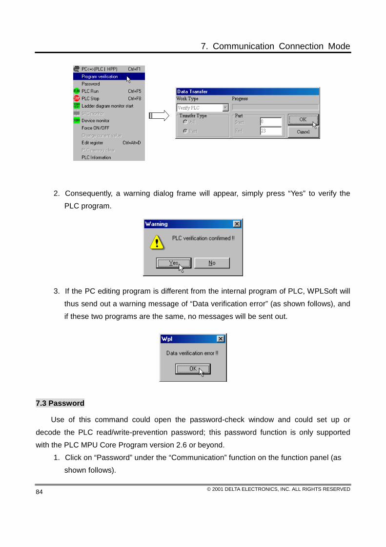
7. Communication Connection Mode
© 2001 DELTA ELECTRONICS, INC. ALL RIGHTS RESERVED 84
2. Consequently, a warning dialog frame will appear, simply press “Yes” to verify the PLC program.
3. If the PC editing program is different from the internal program of PLC, WPLSoft will thus send out a warning message of “Data verification error” (as shown follows), and if these two programs are the same, no messages will be sent out.
7.3 Password
Use of this command could open the password-check window and could set up or decode the PLC read/write-prevention password; this password function is only supported with the PLC MPU Core Program version 2.6 or beyond.
1. Click on “Password” under the “Communication” function on the function panel (as shown follows).

7. Communication Connection Mode
© 2001 DELTA ELECTRONICS, INC. ALL RIGHTS RESERVED 85
Current status of the PLC password
PLC password setup PLC password decoded
2. If the password is forgotten, press the [Space] bar for four times, WPLSoft will then present a confirmation message of “PLC Program delete”, if “Yes” is chosen, the internal program of PLC will be cleared, then the password for the read/write-prevention of PLC will be decoded.
7.4 PLC RUN/STOP
PLC Run:
Click on “PLC Run” under the “Communication” function on the function panel (as shown follows), or type in the compound buttons 〔Ctrl〕+〔F5〕, or click on the icon to enter the warning dialog frame, then press “Yes” to set the PLC MPU at the RUN condition.

7. Communication Connection Mode
© 2001 DELTA ELECTRONICS, INC. ALL RIGHTS RESERVED 86
PLC Stop:
Click on “PLC Stop” under the “Communication” function on the function panel, or type in the compound buttons 〔Ctrl〕+〔F8〕, or click on the icon (as shown follows) to enter the warning dialog frame, then press “Yes” to set the PLC MPU at the STOP condition.
7.5 Ladder Diagram Monitor
Use of this command could switch the ladder diagram mode to the ladder diagram monitor mode, and under the monitor mode, all the editing actions are prohibited. All the

7. Communication Connection Mode
© 2001 DELTA ELECTRONICS, INC. ALL RIGHTS RESERVED 87
execution conditions of the program could be observed from the window, and usually, advantages will be accompanying the ladder diagram monitor mode in the program’s error deletion and the operation outcomes.
1. If users are to monitor the PLC status under the PC window, they firstly will present the ladder diagram window on PC (as shown follows), then click on “Ladder diagram monitor start” under the “Communication” function on the function panel, or click on the icon.
2. When the monitoring has started, the green portion displayed in the window is an indication that the contact of the device is at the continuity status or that the output coil is at the exciting-magnet status, or even, that the application commands are under process. On the contrary, if the green color does not display on the location of the contact, the output coil, and the application command, it means that this portion is currently not in motion. Moreover, the current value (*Footnote 1) of the register will be shown on the upper part of the register, as shown follows.

7. Communication Connection Mode
© 2001 DELTA ELECTRONICS, INC. ALL RIGHTS RESERVED 88
*Footnote 1:
When clicking on “Display value type” under the “Windows” function on the function panel, users could select in between the Hexadecimal, the Decimal or the ASCII code system for display. Under the ladder diagram monitor mode, if the value displayed by the register is of the Decimal system, letter K is represented in the front, while of the Hexadecimal system, letter H is represented, and if it is of the ASCII code, the figure has to be of the ASCII code for display, otherwise, it will be blank.

7. Communication Connection Mode
© 2001 DELTA ELECTRONICS, INC. ALL RIGHTS RESERVED 89
7.6 SFC Monitor
Use of this command could switch the SFC editing mode to the SFC diagram monitor
mode, and under the monitor mode, all the editing actions are prohibited. All the execution
conditions of the program could be observed from the window, and usually, users are to locate
the current execution status from the SFC diagram monitor mode.
1. Press the icon on the tool panel to start the SFC status monitor or click on the
“SFC state monitor” under the “Communication” function on the function panel to
proceed with the monitor.
2. If the red light is “ON” for step points S21 and S31, it means that the step point is
currently “ON” and is running the internal program.

7. Communication Connection Mode
© 2001 DELTA ELECTRONICS, INC. ALL RIGHTS RESERVED 90
7.7 Device Monitor
Device monitor could monitor one single device status or numerous device statuses simultaneously. If users are to view the status of one or more device statuses under the PC window, simply make use of the following procedure for operation:
1. Click on “Device monitor” under the “Communication” function on the function panel, or click on the icon.
2. Double click on the device name at the following diagram or press [Enter] to
introduce the device monitor input dialog window.

7. Communication Connection Mode
© 2001 DELTA ELECTRONICS, INC. ALL RIGHTS RESERVED 91
Key in the device name and the device number at the “Monitor Device Input” dialog window, then press [OK].
3. If users are to monitor other devices under the same window, simply repeat procedures 2 and 3. (*Footnote 1) *Device name: monitor the device name. *Device status: statuses of the devices (X, Y, M, S, T and C) at monitoring; red block displayed when ON, none displayed when OFF. *Setup value: the setup values of devices (T and C) within the program. *Current value (16Bits); the current value (16Bits) of devices (T, C, D) at monitoring will display its own value (16Bit) only; e.g. the current value (16Bits) of T0 is K274 or H0112. *Current value (32Bits); the current value (32Bits) of devices (T, C, D) at monitoring will display its own value (16Bit) and the 32Bits-value of the next device number

7. Communication Connection Mode
© 2001 DELTA ELECTRONICS, INC. ALL RIGHTS RESERVED 92
combination; e.g. the current value (32Bits) of T0 will display the 32Bits-value, K1769472 or H160000, of the T11 and T10 combination.
If users are to select the “Display value type” under the “Window (W)” function, there
are the Hexadecimal, the Decimal, or the ASCⅡ Code for selection. Under the device monitor mode, if the current value (16Bits and 32Bits) displayed by the register is of the Decimal system, letter K is represented in the front, while of the Hexadecimal system, letter H is represented, and if it is of the ASCII code, the figure has to be of the ASCII code for display, otherwise, □ will be displayed.
The WPL editor could conduct three monitors simultaneously:
1. the SFC mode monitor,
2. the device monitor,
3. the ladder diagram monitor.
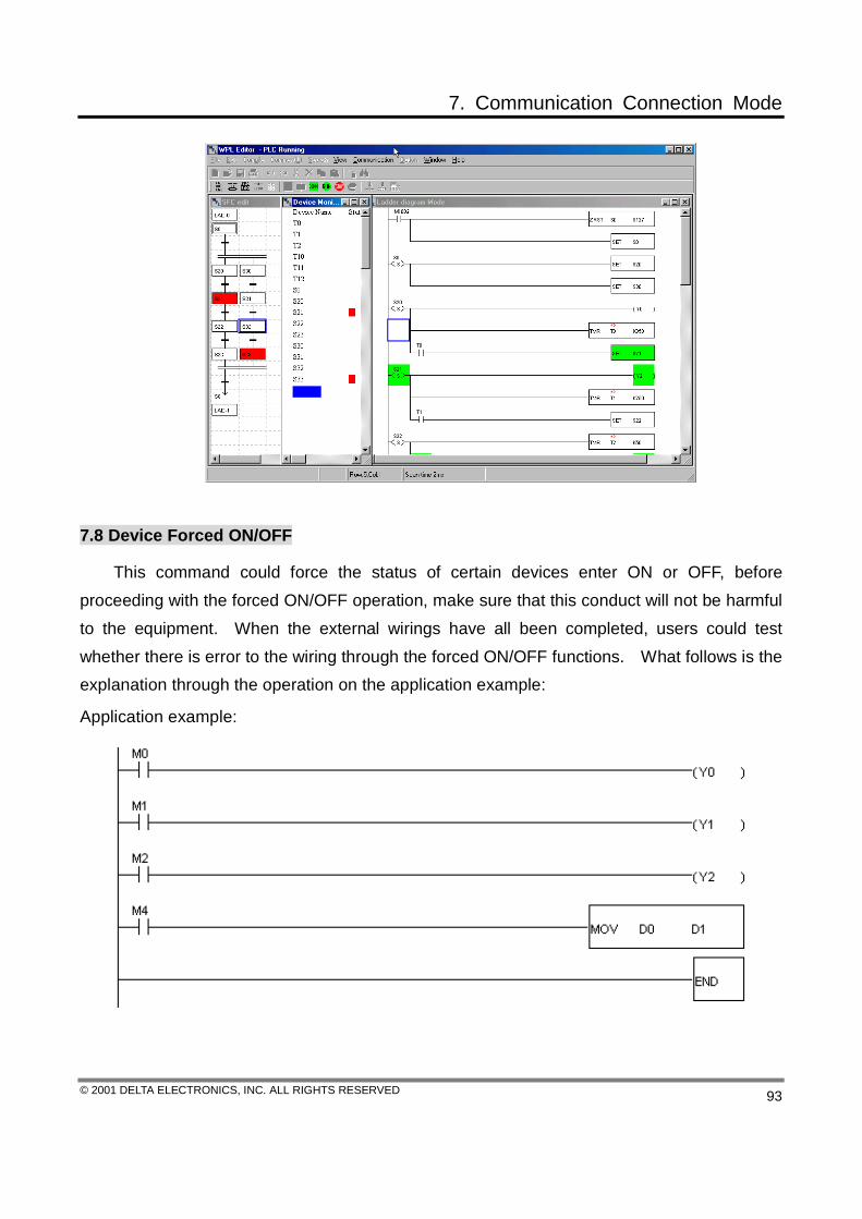
7. Communication Connection Mode
© 2001 DELTA ELECTRONICS, INC. ALL RIGHTS RESERVED 93
7.8 Device Forced ON/OFF
This command could force the status of certain devices enter ON or OFF, before proceeding with the forced ON/OFF operation, make sure that this conduct will not be harmful to the equipment. When the external wirings have all been completed, users could test whether there is error to the wiring through the forced ON/OFF functions. What follows is the explanation through the operation on the application example:
Application example:

7. Communication Connection Mode
© 2001 DELTA ELECTRONICS, INC. ALL RIGHTS RESERVED 94
Method 1:
1. After compiling the above ladder diagram program and have it written in to the PLC, click on the icon to enter the ladder diagram monitor mode, as shown follows.
2. Under the ladder diagram monitor mode, certain functions listed on the tool icon panel are not to be used, and WPLSoft will have these not-to-be-used function icons displayed in relief.
3. Move the mouse to the forced ON/OFF devices (M0), press the right button to introduce a selection dialog window, and click on the forced ON function. (Yhis function could also be used under the device monitor mode)
The ladder diagram monitor mode:
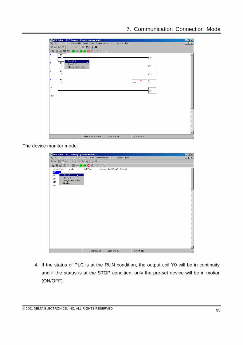
7. Communication Connection Mode
© 2001 DELTA ELECTRONICS, INC. ALL RIGHTS RESERVED 95
The device monitor mode:
4. If the status of PLC is at the RUN condition, the output coil Y0 will be in continuity, and if the status is at the STOP condition, only the pre-set device will be in motion (ON/OFF).

7. Communication Connection Mode
© 2001 DELTA ELECTRONICS, INC. ALL RIGHTS RESERVED 96
Method 2:
1. Click on “Forced ON/OFF” under the “Communication” function on the function panel. (This function could also be used under the device monitor mode)
2. Key in M0 at the device name section under the “Forced ON/OFF” dialog window,

7. Communication Connection Mode
© 2001 DELTA ELECTRONICS, INC. ALL RIGHTS RESERVED 97
then check the “Forced ON” or “Forced OFF” → press “OK”.
7.9 Current Value Setting
This function is only valid under the ladder diagram and the device monitor modes, and use of this command could open a window for the alteration of current values (as shown follows); under this window, users are to proceed with the alteration on the 16/32 bit values towards devices (D, T, C, E, F).
1. Click on “Current value setting” under the “Communication” function on the function panel. (This function could also be used under the ladder diagram or the device monitor modes)
2. If the device is C235, which is of 32-bit, it is thus necessary to select the 32 bit value, or if the device is D0, that is of 16-bit, then select the 16 bit value; however, if the 16-bit D0 device paired up with the 32 bit value, it means that D1 is included, and D1 is thus the upper 16-Bit data and that D0 is the lower 16-Bit data.
3. If input of the current value is of the decimal system, the number should be prefixed with a “K” (e.g. K100), or if it is of the hexadecimal system, the number should be prefixed with an “H” (e.g. H100).
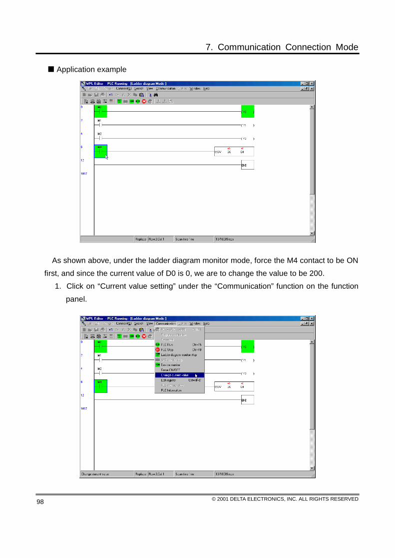
7. Communication Connection Mode
© 2001 DELTA ELECTRONICS, INC. ALL RIGHTS RESERVED 98
Application example
As shown above, under the ladder diagram monitor mode, force the M4 contact to be ON first, and since the current value of D0 is 0, we are to change the value to be 200.
1. Click on “Current value setting” under the “Communication” function on the function panel.

7. Communication Connection Mode
© 2001 DELTA ELECTRONICS, INC. ALL RIGHTS RESERVED 99
2. After the dialog window appears, key in the device name D0 and the current value
K200, then press “OK”.
The current value of the D0 register will be changed to K200.

7. Communication Connection Mode
© 2001 DELTA ELECTRONICS, INC. ALL RIGHTS RESERVED 100
7.10 Edit Register
WPLSoft provides the function of register editing. (As shown follows)
Users could designate the D register, the C register, the high-speed counter register, the T register, among all types of registers, to have the current data of each register undergone data monitoring, setup, and data save and data retrieve (*Footnote 1). There are two ways of displaying: the form display and the line display.
1. Click on “Edit register” under the “Communication” function on the function panel or type in the compound buttons 〈Ctrl〉+〈Alt〉+〈D〉.
2. Appeared the “Register” window, double click on the mouse to set the designated register (e.g. D41) → then appear the D41 input panel, key in the value “1234” → press “OK”; there are the decimal, the hexadecimal, and the binary systems for the value input. (As shown follows)

7. Communication Connection Mode
© 2001 DELTA ELECTRONICS, INC. ALL RIGHTS RESERVED 101
3. After the setup for all the register values is completed, write them “all” or “part” into the PLC data register, then press “OK” for completion.
4. Before writing in, make sure that no bad effects will be incurred to the PLC peripherals that are in operation.
There are numerous functions to edit the register:

7. Communication Connection Mode
© 2001 DELTA ELECTRONICS, INC. ALL RIGHTS RESERVED 102
1. Read the PLC data register: read out the current value of the data register currently connected with the PLC.
2. Write in to the PLC data register: write the current value of the edited data register into the PLC currently in connection.
3. Print all: Print out all the current values of the data register.
4. Print part: Partial print the current values of the data register.
5. Save to the (Disk): Save the edited data register into the disk with the * .RVL file type.(*Footnote 3)
6. Read from (Disk): Read the * .RVL file type from the disk.
7. Clear the data register: clear the data--under the currently edited data register (D, C, the high-speed counter and T)-- that could be written into the PLC.
*Footnote 1:
The file saving/retrieving type of the edited register function is the *.RVL type.
7.11 PLC Memory Clear
WPLSoft provides the PLC memory clear function, a function that is only valid when PLC is at the STOP condition (as shown follows).
1. Click on “PLC memory clear” under the “Communication” function on the function panel.

7. Communication Connection Mode
© 2001 DELTA ELECTRONICS, INC. ALL RIGHTS RESERVED 103
2. The warning dialog frame will appear, and simply press “Yes” to clear the program within PLC.
3. The status panel at the lower right corner of WPLSoft will display the message, “PLC Clearing, please wait!!”.
4. Clear completed.
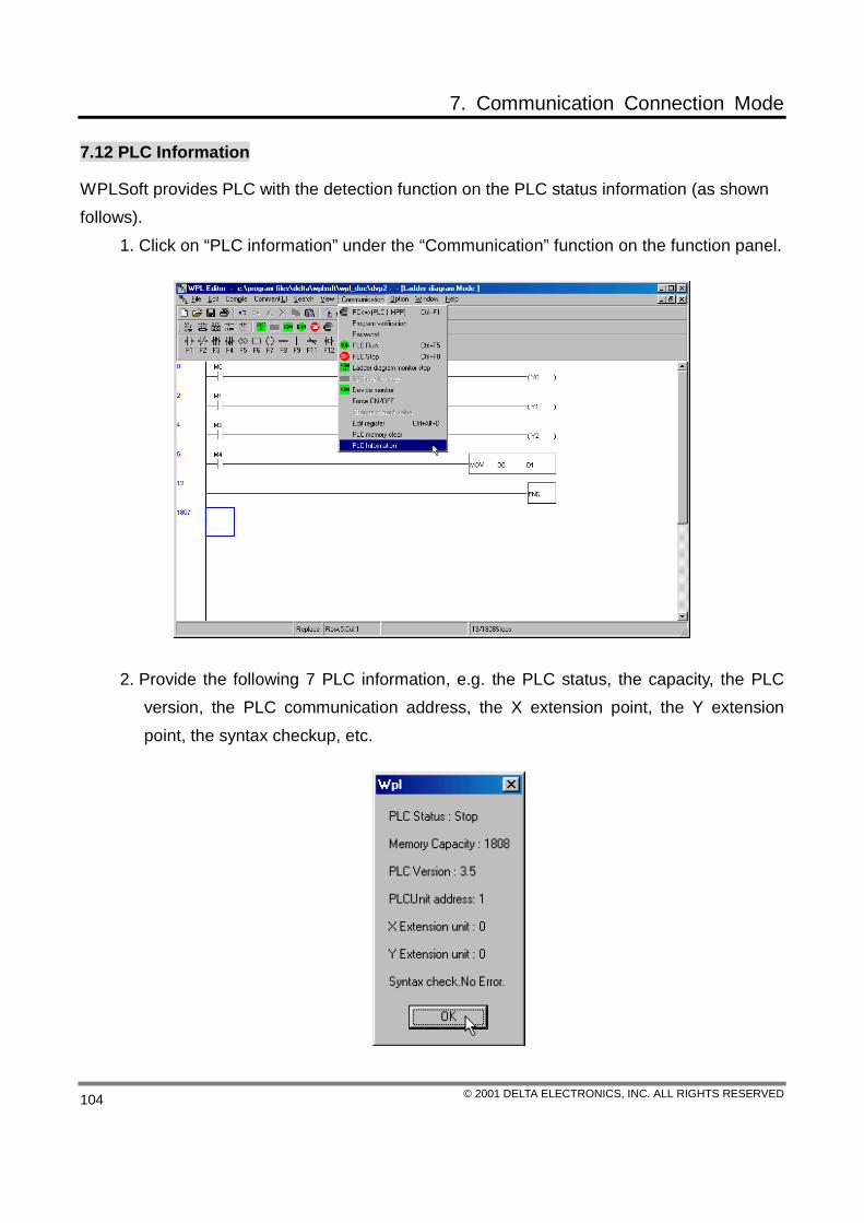
7. Communication Connection Mode
© 2001 DELTA ELECTRONICS, INC. ALL RIGHTS RESERVED 104
7.12 PLC Information
WPLSoft provides PLC with the detection function on the PLC status information (as shown follows).
1. Click on “PLC information” under the “Communication” function on the function panel.
2. Provide the following 7 PLC information, e.g. the PLC status, the capacity, the PLC version, the PLC communication address, the X extension point, the Y extension point, the syntax checkup, etc.

8. SFC Editing Mode
© 2001 DELTA ELECTRONICS, INC. ALL RIGHTS RESERVED 105
8.1 Conditions of the SFC Editing Mode
After the WPL Editor is activated, users could open a new file or open the old files to enter the SFC editing mode, and use the SFC diagram (the Sequence Function Chart) to edit the programs, as shown follows.
Editing block
Location of the editing block Usage status of the memory
The Ladder Diagram tool bar
The general tool bar
Icons of the SFC tool panel are displayed on the upper side of the SFC mode page.
When using the SFC diagram, users could simply click on the icons or press the compound
button, 〔Shift〕 first, then move the mouse to the editing icon, or moreover, to use the function
keys ((F1~F9), 〔Shift〕 + (F1~F9)) as another input method. What follows will be
explanations on the operation procedure of every method.
8.2 Basic Operation
SFC Editing Principles:

8. SFC Editing Mode
© 2001 DELTA ELECTRONICS, INC. ALL RIGHTS RESERVED 106
The SFC Principles are set up based upon the international standard, IEC1131-3, and is
of the diagram editing mode. The whole structure looks like a flow chart and it is to utilize
the Step Relay S within the PLC; the number of every Step Relay S is to serve as a step point,
which is identical to every procedure of the flow chart. After current procedures are dealt
with, move on to the next step (which is the next step point S) requested according to the
preset terms, in this case, users could simply follow the procedure repetitively to obtain the
best results.
Icons and the icon explanations of the SFC tool panel:
Icons of the SFC tool panel
Explanations: (to operate with the click of the mouse or use the function keys (F1~F9) and〔Shift〕+ (F1~F9))
The ladder diagram mode: this diagram suggests that the internal editing program is of the general ladder diagram with non-step-ladder program.
Diagram for the initial step point: this double-framed diagram suggests that this is a diagram for the initial step point of SFC, and the device range goes from S0~S9.
Diagram for the general step point: the device range to be used goes from S10~S1023. (the device range feasible for models ES, EX and SS goes from S10~S127)
Jump diagram for the step point: to be used when the status of the step point is to be transferred to a step point that is not right next to it. (for jumps to go upward or downward between step points of the same process but not next to each other, or for jumps between different processes)
The transfer condition diagram of the step point: conditions of the status transfer among every step point.
The selection divergence diagram: transfer the status to its corresponding step point from the same step point with different transfer conditions. (if the divergence is consisted of more than two points, operate with the function keys 〔Shift〕+ (F1~F9) to add more points for the divergence)

8. SFC Editing Mode
© 2001 DELTA ELECTRONICS, INC. ALL RIGHTS RESERVED 107
The selection convergence diagram: under the transfer condition, transfer the status to a common step point from two (or more) different step points. (if the convergence is consisted of more than two points, operate with the function keys 〔Shift〕+ (F1~F9) to add more points for the convergence)
The simultaneous divergence diagram: under the same transfer condition, transfer the status from the common step point to two (or more) step points. (if the divergence is consisted of more than two points, operate with the function keys 〔Shift〕+ (F1~F9) to add more points for the divergence)
The simultaneous convergence diagram: when statuses of two (or more) different step points are valid, transfer them to the same step point under the same transfer condition. (if the convergence is consisted of more than two points, operate with the function keys 〔Shift〕+ (F1~F9) to add more points for the convergence)
〔Shift〕+ The simultaneous divergence connection diagram
〔Shift〕+ The simultaneous connection diagram
〔Shift〕+ The simultaneous convergence connection diagram
〔Shift〕+ The simultaneous connection diagram
〔Shift〕+ The selection divergence connection diagram
〔Shift〕+ The selection connection diagram
〔Shift〕+ The selection convergence connection diagram

8. SFC Editing Mode
© 2001 DELTA ELECTRONICS, INC. ALL RIGHTS RESERVED 108
〔Shift〕+ The selection connection diagram
〔Shift〕+ The vertical-line connection diagram
The SFC Editing Condition:
The editing range of the SFC editing condition is consisted of 16 units on the horizontal
direction, whereas there is no limit on the vertical direction. Every dotted rectangular lattice
stands for one unit, and therefore, a maximum of 16 diagrams could be shown on the same
horizontal level at the same time.
The SFC editing method:
Method 1: Arrange all the SFC diagrams first before proceeding with the internal program
design of the individual diagram.
Procedure 1: After enter the SFC editing mode, icons of the SFC tool panel would be
spotted instantly. Generally speaking, the ladder diagram mode will be the

8. SFC Editing Mode
© 2001 DELTA ELECTRONICS, INC. ALL RIGHTS RESERVED 109
first one to show up (press the function key F1, or click on the SFC tool
panel icon, ), for it is the initial step point device S0〜S9 to direct the
process into the SFC structure. Regular PLC program design will not
normally direct the procedure into the SFC structure in the first place,
therefore, the internal program of the first LAD-0 diagram is usually the
pre-program to enter the SFC structure.
Procedure 2: Mapping out the initial step point diagram (press the function key F2, or click
on the SFC tool panel icon, ) and choose among the initial step points
S0~S9; this will be the first step status point to enter the SFC structure. (The
initial step points could be applied to S0~S9 only, if step points with different
numbering are utilized as the initial step points, the SFC diagram error
message will be displayed at the very last editing process of the program. If
the initial step points to be edited with the ladder diagram mode or the
command mode are not of S0~S9, the SFC diagram cannot be converted
correctly at the very last editing process of the program).
Procedure3: The transfer condition diagram must exist among different step point diagram
(press the function key F5, or click on the SFC tool panel icon, ) so as to
enable the statuses of every step point to be transferred to other step points
based on the transfer condition; the internal program of the step point
diagram writes program that is to be executed up to this step point only, and
the internal program of the transfer condition diagram writes conditions of the
status transfer among different step points. (If the transfer status to certain
step point written by the internal program of the transfer condition diagram is

8. SFC Editing Mode
© 2001 DELTA ELECTRONICS, INC. ALL RIGHTS RESERVED 110
different from the transfer step point plotted by the external SFC diagram, the
diagram plotted by the SFC diagram will serve as the standard to be utilized
after the program is edited thoroughly.)
Procedure 4: When the SFC diagram is edited, use the far left unit as the criterion, then go
then editing in order the far right units and the lower units; before the
programs are yet to be edited within every diagram, the color gray is thus
used to represent the situation that there is no program within the diagram.
Users could thus edit the internal program (there are two ways to do it: firstly,
place the editing block onto the diagram that is to be edited, then select the
Internal Ladder Diagram Mode or the Internal Command Mode for editing
from the function panel on the right button of the mouse; keep in mind that
only one mode is to be chosen at one time); if there are programs within the
diagram, the background color will be white.
Procedure 5: When editing the SFC diagram, the lower step point that followed could be
connected with general step point diagrams (press the function key F3, or
click on the SFC tool panel icon, ), however, if the point is to jump upward
or downward to points that are not next to it, or return to the initial step point
or even jump to other step points on a different procedure, the Jump
Diagram is thus to be utilized (press the function key F4, or click on the SFC
tool panel icon, ); the device number for every general step point diagram
and initial step point diagram could only show up for one time during the
SFC diagram editing. As shown on the above diagram, S12 and S13 are
next to each other, and it will thus be sufficient to use the general step point

8. SFC Editing Mode
© 2001 DELTA ELECTRONICS, INC. ALL RIGHTS RESERVED 111
diagram, however, if S13 is to return to the initial step point S0, it is then
necessary to use the jump symbol for the status transfer.
Method 2: Or we could complete each SFC diagram and its internal program individually
before arranging the whole set of the SFC diagram.
Procedure 1: When start editing, select the ladder diagram mode first as the pre-program
to enter the SFC structure, and simply press the function key F1, or click on
the SFC tool panel icon, , will be okay. The users are to place the
editing block onto the far left unit first, and when it comes to LAD-□ of the
SFC editing window, the □ numbering will keep on increasing automatically
along with the number of times that the icon is selected; if the location of
the editing block is incorrect, it will show instantly an error message
regarding the incorrect input location.
Procedure 2: After locating the ladder diagram LAD-0, the background color will be gray
for the LAD-0 diagram in the beginning, which means that there is no
program within the LAD-0 diagram; we then input the internal program to the
ladder diagram. Move the editing block to the ladder diagram, then press

8. SFC Editing Mode
© 2001 DELTA ELECTRONICS, INC. ALL RIGHTS RESERVED 112
the right button on the mouse to display the function panel.

8. SFC Editing Mode
© 2001 DELTA ELECTRONICS, INC. ALL RIGHTS RESERVED 113
Procedure 3: Users could use the internal ladder diagram mode or the internal command
mode for editing based on his/her own regular editing practices.
The Internal Ladder Diagram Mode Editing:
The Internal Command Mode Editing:
Procedure 4: After the editing is completed, close the internal ladder diagram mode or the
internal command mode; the program that was just edited would be saved in
the LAD-0 diagram, and the background color of the LAD-0 diagram will turn
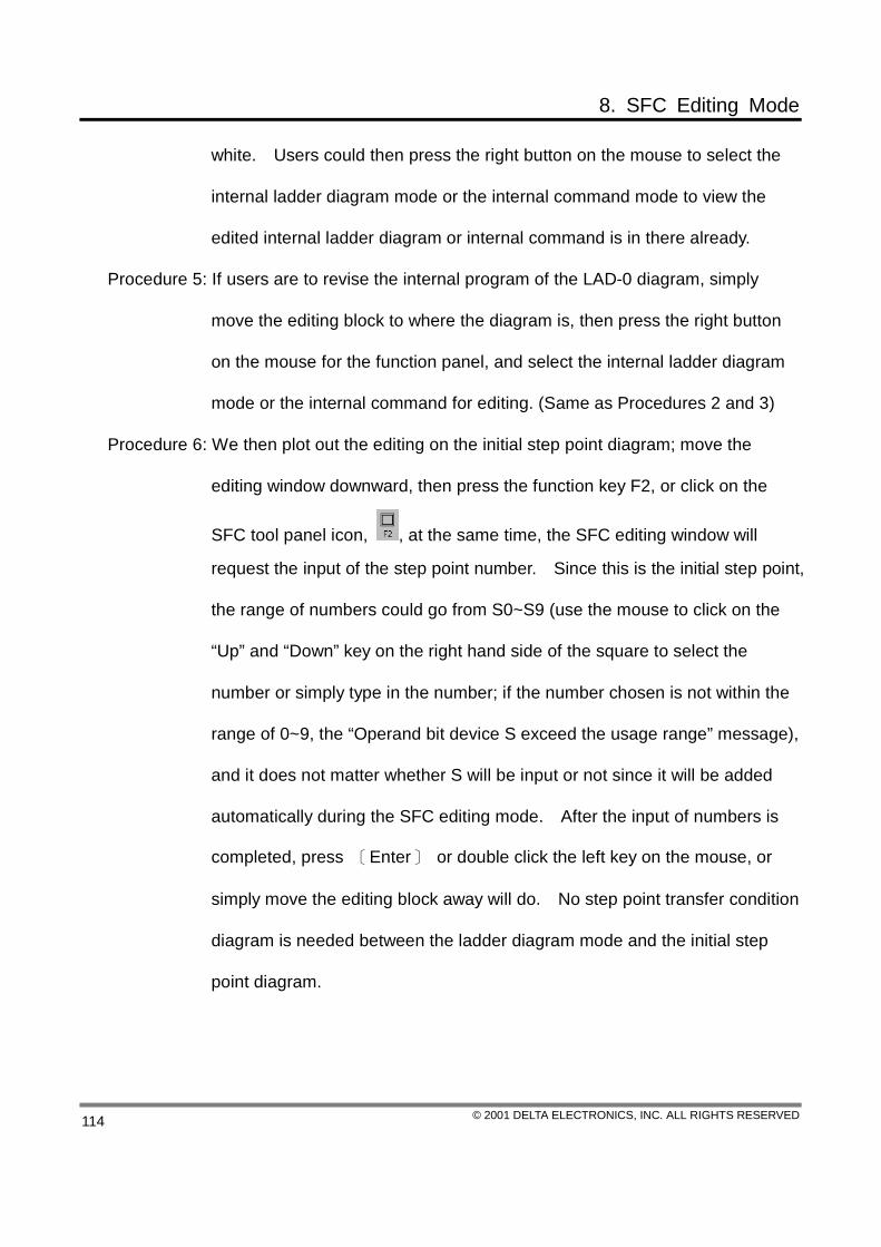
8. SFC Editing Mode
© 2001 DELTA ELECTRONICS, INC. ALL RIGHTS RESERVED 114
white. Users could then press the right button on the mouse to select the
internal ladder diagram mode or the internal command mode to view the
edited internal ladder diagram or internal command is in there already.
Procedure 5: If users are to revise the internal program of the LAD-0 diagram, simply
move the editing block to where the diagram is, then press the right button
on the mouse for the function panel, and select the internal ladder diagram
mode or the internal command for editing. (Same as Procedures 2 and 3)
Procedure 6: We then plot out the editing on the initial step point diagram; move the
editing window downward, then press the function key F2, or click on the
SFC tool panel icon, , at the same time, the SFC editing window will
request the input of the step point number. Since this is the initial step point,
the range of numbers could go from S0~S9 (use the mouse to click on the
“Up” and “Down” key on the right hand side of the square to select the
number or simply type in the number; if the number chosen is not within the
range of 0~9, the “Operand bit device S exceed the usage range” message),
and it does not matter whether S will be input or not since it will be added
automatically during the SFC editing mode. After the input of numbers is
completed, press 〔Enter〕 or double click the left key on the mouse, or
simply move the editing block away will do. No step point transfer condition
diagram is needed between the ladder diagram mode and the initial step
point diagram.
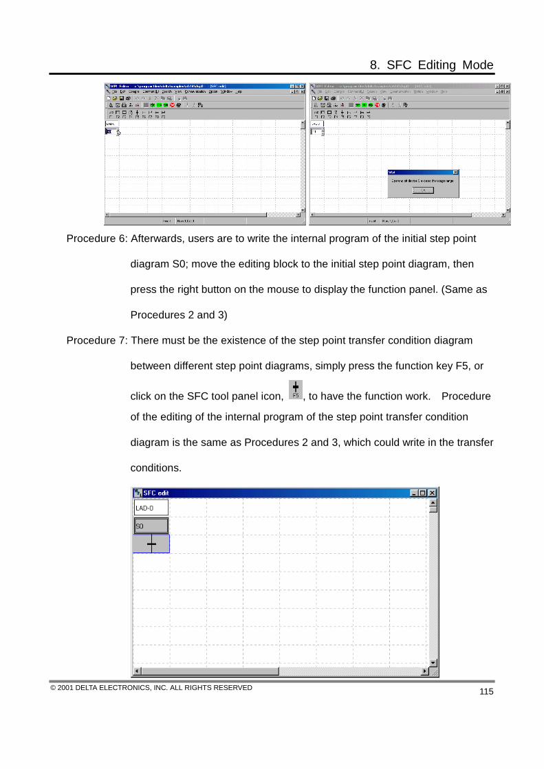
8. SFC Editing Mode
© 2001 DELTA ELECTRONICS, INC. ALL RIGHTS RESERVED 115
Procedure 6: Afterwards, users are to write the internal program of the initial step point
diagram S0; move the editing block to the initial step point diagram, then
press the right button on the mouse to display the function panel. (Same as
Procedures 2 and 3)
Procedure 7: There must be the existence of the step point transfer condition diagram
between different step point diagrams, simply press the function key F5, or
click on the SFC tool panel icon, , to have the function work. Procedure
of the editing of the internal program of the step point transfer condition
diagram is the same as Procedures 2 and 3, which could write in the transfer
conditions.
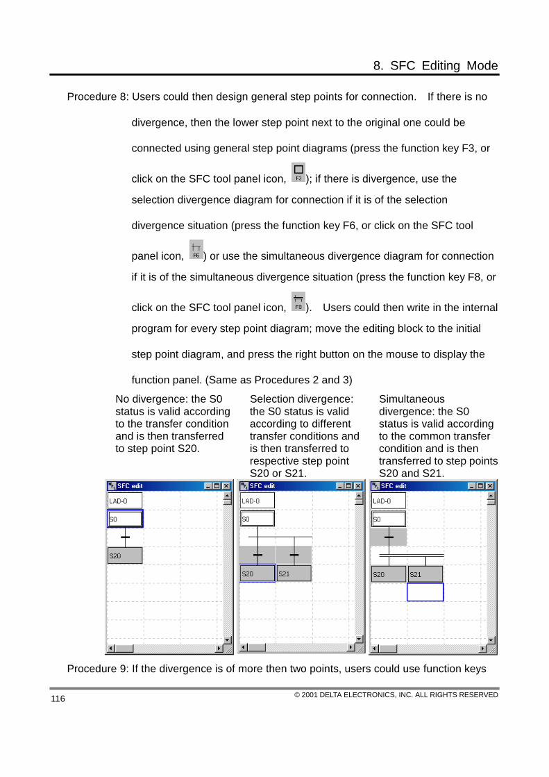
8. SFC Editing Mode
© 2001 DELTA ELECTRONICS, INC. ALL RIGHTS RESERVED 116
Procedure 8: Users could then design general step points for connection. If there is no
divergence, then the lower step point next to the original one could be
connected using general step point diagrams (press the function key F3, or
click on the SFC tool panel icon, ); if there is divergence, use the
selection divergence diagram for connection if it is of the selection
divergence situation (press the function key F6, or click on the SFC tool
panel icon, ) or use the simultaneous divergence diagram for connection
if it is of the simultaneous divergence situation (press the function key F8, or
click on the SFC tool panel icon, ). Users could then write in the internal
program for every step point diagram; move the editing block to the initial
step point diagram, and press the right button on the mouse to display the
function panel. (Same as Procedures 2 and 3)
No divergence: the S0 status is valid according to the transfer condition and is then transferred to step point S20.
Selection divergence: the S0 status is valid according to different transfer conditions and is then transferred to respective step point S20 or S21.
Simultaneous divergence: the S0 status is valid according to the common transfer condition and is then transferred to step points S20 and S21.
Procedure 9: If the divergence is of more then two points, users could use function keys

8. SFC Editing Mode
© 2001 DELTA ELECTRONICS, INC. ALL RIGHTS RESERVED 117
〔Shift〕+ (F1~F9) to add more divergence points. (For the simultaneous
divergence connection diagram, press 〔Shift〕+ ; for the simultaneous
convergence connection diagram, press 〔Shift〕+ ; for the simultaneous
convergence connection diagram, press 〔Shift〕+ ; for the selection
divergence connection diagram, press 〔Shift〕+ ; for the selection
connection diagram, press 〔Shift〕+ , and for the selection connection
diagram, press 〔Shift〕+ )
Procedure 10: After the divergence occurred, it is then necessary to converge all the step
points, and there are there types, the selection convergence and the
simultaneous convergence. For the selection convergence diagram, simply
press the function key F7, or click on the SFC tool panel icon, , and as for
the simultaneous convergence diagram, press the function key F9, or click
on the SFC tool panel icon, . Users could then write in the internal
program for every step point diagram; move the editing block to the initial
step point diagram, and press the right button on the mouse to display the
function panel. (Same as Procedures 2 and 3)
Selection convergence: the status of S30, S31 or S32 is valid based on each respective transfer condition and is thus transferred to the common step point S40.
Simultaneous convergence: statuses of S30, S31 or S32 are valid at the same time and are transferred to step point S40 based on the same transfer condition.
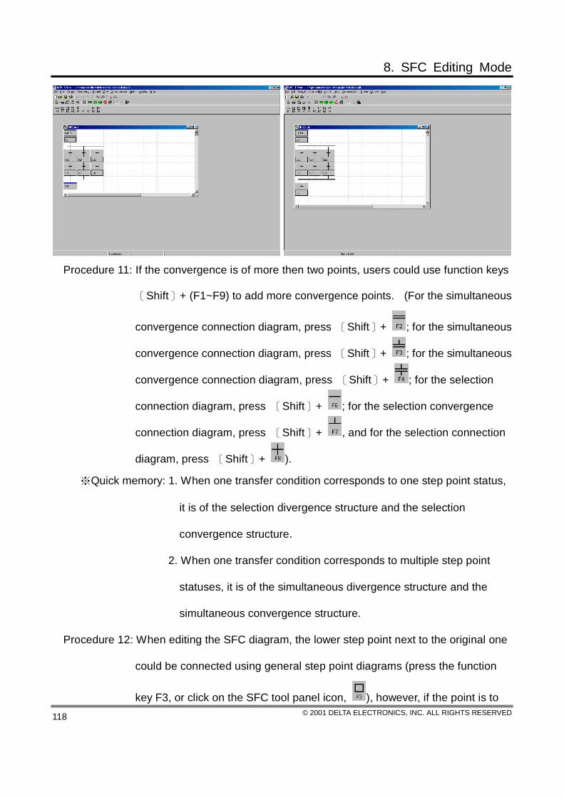
8. SFC Editing Mode
© 2001 DELTA ELECTRONICS, INC. ALL RIGHTS RESERVED 118
Procedure 11: If the convergence is of more then two points, users could use function keys
〔Shift〕+ (F1~F9) to add more convergence points. (For the simultaneous
convergence connection diagram, press 〔Shift〕+ ; for the simultaneous
convergence connection diagram, press 〔Shift〕+ ; for the simultaneous
convergence connection diagram, press 〔Shift〕+ ; for the selection
connection diagram, press 〔Shift〕+ ; for the selection convergence
connection diagram, press 〔Shift〕+ , and for the selection connection
diagram, press 〔Shift〕+ ).
※Quick memory: 1. When one transfer condition corresponds to one step point status,
it is of the selection divergence structure and the selection
convergence structure.
2. When one transfer condition corresponds to multiple step point
statuses, it is of the simultaneous divergence structure and the
simultaneous convergence structure.
Procedure 12: When editing the SFC diagram, the lower step point next to the original one
could be connected using general step point diagrams (press the function
key F3, or click on the SFC tool panel icon, ), however, if the point is to

8. SFC Editing Mode
© 2001 DELTA ELECTRONICS, INC. ALL RIGHTS RESERVED 119
jump upward or downward to points that are not next to it, or return to the
initial step point or even jump to other step points on a different procedure,
the Jump Diagram is thus to be utilized (press the function key F4, or click
on the SFC tool panel icon, ); the device number for every general step
point diagram and initial step point diagram could only show up for one time
during the SFC diagram editing.
Step point S10 is right next to step points S11 and S12, and it is sufficient to use general step point diagrams only; if step point S13 is to return to the initial step point S0, the step point jump diagram will be used to do the status transfer. Return to the S0 initial step point with the same procedure.
If the status of step point S20 within the S1 procedure is transferred to step point S10 within the S0 procedure, the step point jump diagram is the used to do the status transfer. The status transfer of two SFC diagrams with two different procedures.
Procedure 13: After the SFC diagram is edited, convert the SFC status diagram into the
command codes through compiling; select Compile (P) from the function
panel, then click on “SFC ” command or use the mouse to click on the
function icon, and press the compound keys 〔Ctrl〕+〔F6〕 to have this
function worked.
Select Compile (P) from the function panel, then click on “SFC ” command to convert the SFC status diagram into the command codes
Use the mouse to click on the function icon,
to convert the SFC status diagram into the command codes

8. SFC Editing Mode
© 2001 DELTA ELECTRONICS, INC. ALL RIGHTS RESERVED 120
8.3 Auxiliary Editing
The SFC status diagram is compiled into the command codes: (if to show correctly the
ladder diagram for compiling, it is necessary to go through the process of compiling the
SFC status diagram into the command codes, then compile the command codes into the
ladder diagram)
The SFC status diagram of simultaneous divergence and simultaneous convergence: 1.→The SFC status diagram compiled into the command codes, 2.→the command codes compiled into the ladder diagram

8. SFC Editing Mode
© 2001 DELTA ELECTRONICS, INC. ALL RIGHTS RESERVED 121
The SFC status diagram of selection divergence and selection convergence: 1.→The SFC status diagram compiled into the command codes, 2.→the command codes compiled into the ladder diagram
Label of the SFC mode editing device:
Since the SFC status diagram is to be represented through device S, the labeling for
SFC will then be the labeling for device S.
Labeling of the SFC mode editing device could firstly select the View (V) function from the function panel, then click on the “View the device labeling window” or press the compound keys 〔Ctrl〕+〔Alt〕+〔M〕 to simultaneously edit multiple device labeling.
Within the device editing window, select the device type, S, then double click the mouse at the site where the device number is to be edited, or use the “Up” and “Down” key to select its target and press 〔Enter〕, the editing panel will be displayed then, simply type in the labeling and press〔Enter〕 will do.

8. SFC Editing Mode
© 2001 DELTA ELECTRONICS, INC. ALL RIGHTS RESERVED 122
Labeling of the SFC mode editing device could firstly select the Label (L) function from the function panel, then click on the “Edit the device labeling” or press the compound keys 〔Ctrl〕+〔F2〕.

8. SFC Editing Mode
© 2001 DELTA ELECTRONICS, INC. ALL RIGHTS RESERVED 123
If the location of the editing block is not to input the device labeling, the message, “Stop input device comment” will show up!
Place the editing block onto the labeling diagram that is to be input, then press the right button of the mouse to select among the editing device labeling choices.

8. SFC Editing Mode
© 2001 DELTA ELECTRONICS, INC. ALL RIGHTS RESERVED 124
After the previous procedure, the editing device labeling window will show up. Input the labeling and press “Save” or 〔Enter〕, then click on “Exit” to close the window.
Click on the general tool panel icon,
, or select “View (V)” from the function panel and then click on “Device comment display”, or press the compound keys 〔Ctrl〕+〔Alt〕+〔C〕 to have the device comment shown on the SFC diagram.
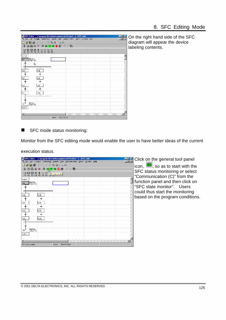
8. SFC Editing Mode
© 2001 DELTA ELECTRONICS, INC. ALL RIGHTS RESERVED 125
On the right hand side of the SFC diagram will appear the device labeling contents.
SFC mode status monitoring:
Monitor from the SFC editing mode would enable the user to have better ideas of the current
execution status.
Click on the general tool panel icon, , so as to start with the SFC status monitoring or select “Communication (C)” from the function panel and then click on “SFC state monitor”. Users could thus start the monitoring based on the program conditions.
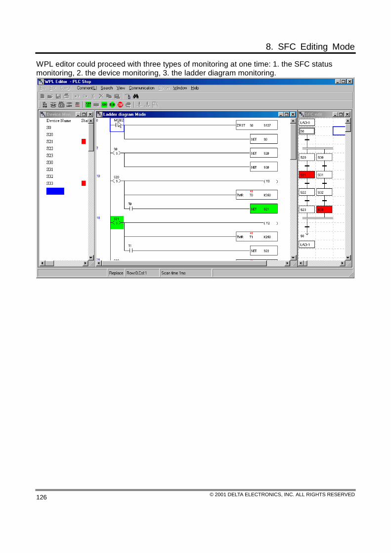
8. SFC Editing Mode
© 2001 DELTA ELECTRONICS, INC. ALL RIGHTS RESERVED 126
WPL editor could proceed with three types of monitoring at one time: 1. the SFC status monitoring, 2. the device monitoring, 3. the ladder diagram monitoring.

8. SFC Editing Mode
© 2001 DELTA ELECTRONICS, INC. ALL RIGHTS RESERVED 127
Examples of the frequently seen errors with the SFC mode:
Error SFC diagram Revised (Correct) SFC diagram 1. Two consecutive step point transfer
condition diagrams exist between two step points.
Only one step point transfer condition diagram could exist between two step points.
2. The S0 step point does not connect with the step point transfer condition diagram.
The S0 step point connects with the step point transfer condition diagram.
3. After the selection divergence, the S0 step point does not connect with the step point transfer condition diagram.
The S0 step point connects with the step point transfer condition diagram after the selection divergence.
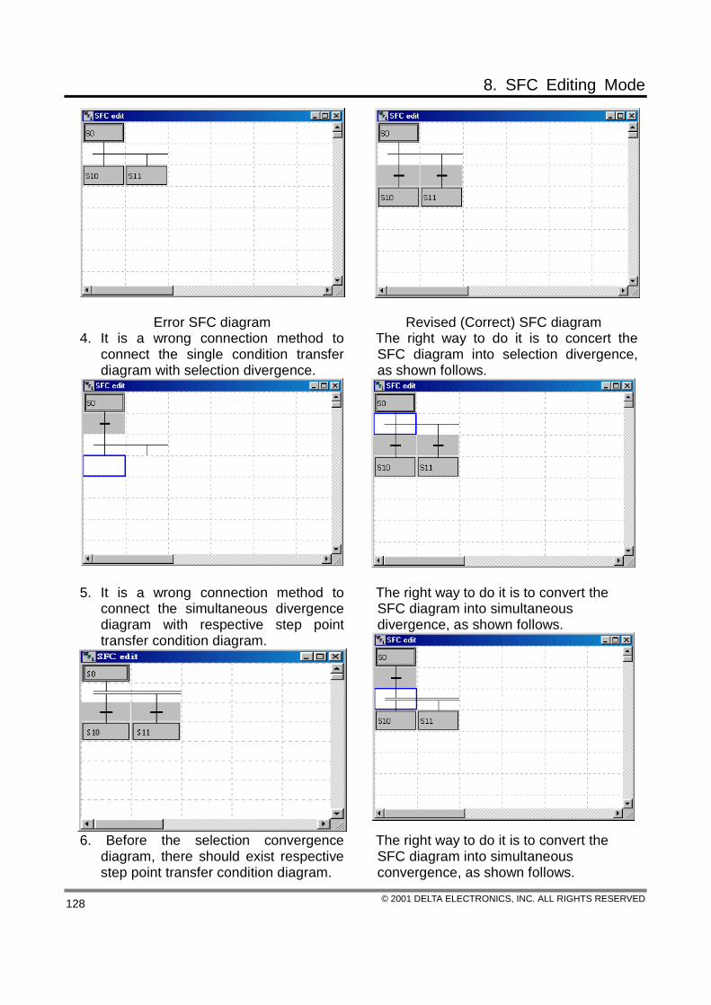
8. SFC Editing Mode
© 2001 DELTA ELECTRONICS, INC. ALL RIGHTS RESERVED 128
Error SFC diagram Revised (Correct) SFC diagram 4. It is a wrong connection method to
connect the single condition transfer diagram with selection divergence.
The right way to do it is to concert the SFC diagram into selection divergence, as shown follows.
5. It is a wrong connection method to connect the simultaneous divergence diagram with respective step point transfer condition diagram.
The right way to do it is to convert the SFC diagram into simultaneous divergence, as shown follows.
6. Before the selection convergence diagram, there should exist respective step point transfer condition diagram.
The right way to do it is to convert the SFC diagram into simultaneous convergence, as shown follows.

8. SFC Editing Mode
© 2001 DELTA ELECTRONICS, INC. ALL RIGHTS RESERVED 129
7. No respective step point transfer
condition diagram should exist before the simultaneous convergence diagram, and should have the step point transfer condition diagram connected to it.
The right way to do it is to convert the SFC diagram into selection convergence, as shown follows.

9. Appendix
© 2001 DELTA ELECTRONICS, INC. ALL RIGHTS RESERVED 129
Data 1: Operation Key and the Speedy Key-in Functions The operation key and the speedy key –in functions of the WPLSoft software is shown as
follows: after the selection sheet is pulled down, most of the speedy key-in buttons will be displayed on the right-hand side of each selection item.
Functions Operation Procedure Operation Keys (Compound Keys) Icons
Move the editing block one section upward 〔↑〕
Move the editing block one section downward 〔↓〕
Move the editing block one section to the left 〔←〕
Move the editing block one section to the right 〔→〕
Move the editing block to the front of the row 〔Home〕
Move the editing block to the end of the row 〔End〕
Delete the symbol locates to the left of the editing block
〔←Backspace〕
Move to the next page 〔Page Down〕
Move to the previous page 〔Page Up〕
Cancel the chosen functions 〔Esc〕
Normally open contact 〔F1〕
Normally closed contact 〔F2〕
The positive-end touch-off contact 〔F3〕
The negative-end touch-off contact 〔F4〕
Step points 〔F5〕
Application commands 〔F6〕
Output coils 〔F7〕
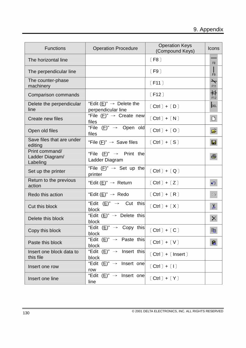
9. Appendix
© 2001 DELTA ELECTRONICS, INC. ALL RIGHTS RESERVED 130
Functions Operation Procedure Operation Keys (Compound Keys) Icons
The horizontal line 〔F8〕
The perpendicular line 〔F9〕
The counter-phase machinery 〔F11〕
Comparison commands 〔F12〕
Delete the perpendicular line
“Edit (E)” → Delete the perpendicular line
〔Ctrl〕+〔D〕
Create new files “File (F)” → Create new files
〔Ctrl〕+〔N〕
Open old files “File (F)” → Open old files
〔Ctrl〕+〔O〕 Save files that are under editing “File (F)” → Save files 〔Ctrl〕+〔S〕 Print command/ Ladder Diagram/ Labeling
“File (F)” → Print the Ladder Diagram
Set up the printer “File (F)” → Set up the printer
〔Ctrl〕+〔Q〕
Return to the previous action “Edit (E)” → Return 〔Ctrl〕+〔Z〕
Redo this action “Edit (E)” → Redo 〔Ctrl〕+〔R〕
Cut this block “Edit (E)” → Cut this block
〔Ctrl〕+〔X〕
Delete this block “Edit (E)” → Delete this block
Copy this block “Edit (E)” → Copy this block
〔Ctrl〕+〔C〕
Paste this block “Edit (E)” → Paste this block
〔Ctrl〕+〔V〕 Insert one block data to this file
“Edit (E)” → Insert this block
〔Ctrl〕+〔Insert〕
Insert one row “Edit (E)” → Insert one row
〔Ctrl〕+〔I〕
Insert one line “Edit (E)” → Insert one line
〔Ctrl〕+〔Y〕

9. Appendix
© 2001 DELTA ELECTRONICS, INC. ALL RIGHTS RESERVED 131
Functions Operation Procedure Operation Keys (Compound Keys) Icons
Delete one device “Edit (E)” → Delete one device
〔Ctrl〕+〔Delete〕
Edit the program subject “Edit (E)” → Edit the program subject
〔Ctrl〕+〔Alt〕+〔T〕
Switch to the command editing mode
“View (V)” → View the command window
〔Ctrl〕+〔Alt〕+〔I〕 Switch to the Ladder Diagram editing mode
“View (V)” → View the ladder diagram window
〔Ctrl〕+〔Alt〕+〔L〕
View the labeling window “View (V)” → View the labeling window
〔Ctrl〕+〔Alt〕+〔M〕 Switch to whether the display of labeling is needed
“View (V)” → Display the labeling
〔Ctrl〕+〔Alt〕+〔C〕
Switch of the ladder diagram monitoring mode
“Communication (C) → START of the ladder diagram monitoring
Monitor the designated device
“Communication (C) → Device monitoring
Allow PLC enter the “RUN” status
“Communication (C) → PLC “RUN”
〔Ctrl〕+〔F5〕 Stop the “RUN” action of PLC
“Communication (C) → PLC “STOP”
〔Ctrl〕+〔F8〕 Communicate with PLC/HPP
“Communication (C) →PC<=>(PLC∣HPP) 〔Ctrl〕+〔F1〕
View the register “Communication (C) → View the register
〔Ctrl〕+〔Alt〕+〔D〕
Convert the command to the ladder diagram
“Compile (P) → Ladder Diagram ‥> Command 〔Ctrl〕+〔F11〕
Convert the ladder diagram to the command
“Compile (P) → Command ‥> Ladder Diagram
〔Ctrl〕+〔F10〕
Jump to designated Steps “Search (S) → Jump 〔Ctrl〕+〔F〕 Find or replace the device name
“Search (S) → Fine/Replace
〔Ctrl〕+〔R〕 Return to START of the program
“Search (S) → Jump to the START of the program
〔Ctrl〕+〔Home〕
Jump to the END of the program
“Search (S) → Jump to the END of the program
〔Ctrl〕+〔End〕

9. Appendix
© 2001 DELTA ELECTRONICS, INC. ALL RIGHTS RESERVED 132
Data 2: Example Program

9. Appendix
© 2001 DELTA ELECTRONICS, INC. ALL RIGHTS RESERVED 133

9. Appendix
© 2001 DELTA ELECTRONICS, INC. ALL RIGHTS RESERVED 134
Data 3: Index Function (not supported currently)
In the “Help (H)” function, users could press the index selections to check other information related to the subject and receive more assistance from the explanatory index.