Embed Size (px)
Citation preview
Pro1Al 956 HIGH COCENTRAT ION STANDRD AEROSOL OENERATOSU)SOUTHERN RESEARCH INST DIRNINOHR AL
FARTHING ET AL. 31 JUL 85 SORI-ERS-85-724UNCLRSSIFIED DRRK1-83-C-038 F/C 13/? L
EE--EE-IIIImhEElhhlhlllEIIIIIIIIIIIIIII
"WI".-"IIII
_7~
JW2.8
11111~112.0
11111125 114~ 1.6 jjII
MICRCOP'CHART
4*. -

In
(a8o51.flRS-05-724
9IGS CONCUMTRAT!ON STANARD AEROSOL GENERATOR
Final Comprehensive Report
Pregared f at theU.S. Army Armament Research and Development CommandCbemical/Vallistaos Procurement DivisionAberdeen Prov~ing OrondEdgevood Area, Maryland 21010
DTICa. ELECTE
APPROVED FOR PUBLIC RELEASE
DISTRIBUTION IS UNLIMITED
* Soute Research Institute
1 ~ ~8642104~~ 0ar 5
j.. . . . . . .. . .

-4,umu jj L .. 11 . . q."*.*,*ub*,iqu--,-WY,1 U"' F','--,,,. -,-.-. -. ..
,-- .; - . --*. - .--- . . . . - .d .
SoRI-EAS-85-724
Final Comprehensive Report "V
HIGH CONCENTRATION STANDARD AEROSOL GENERATOR.-
William E. FarthingRandal S. Martin
Southern Research Institute2000 Ninth Avenue South
P.O. Box 55305Birmingham, AL 35255-5305
July 31, 1985
Contract DAAKI 1-83-C-0038A002 Final Comprehensive Report
Project Officer: Dr. Jerry BottigerObscuration Sciences Section
Prepared forU.S. Army Armament Research and Development Command
Chemical/Ballistics Procurement DivisionAberdeen Proving Ground
Edgewood Area, Maryland 21010
'.-
Project #5335
APPROVED FOR PUBLIC RELEASE
DISTRIBUTION IS UNLIMITED
S.M.............. ....... :...... . ..... ........... ................. ..... ..I... ................................. ........... .-................
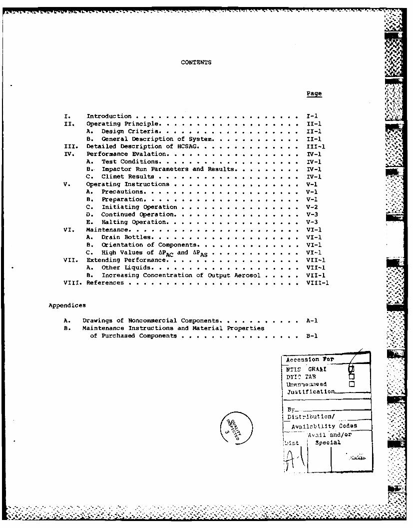
CONTENTS
Page
A. Design Criteria . . . . . .. .0 . ... . . . . . . 1-B. General Description of System .... . . . . . . . 1-
III. Detailed Description of HCSAG . . . . . . . . .. Il-IV* Performance Evalation ... .. .. .. . ... .. .. IV-l
A. Test Conditions. .. ................. . . IV-l \
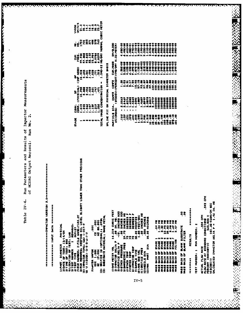
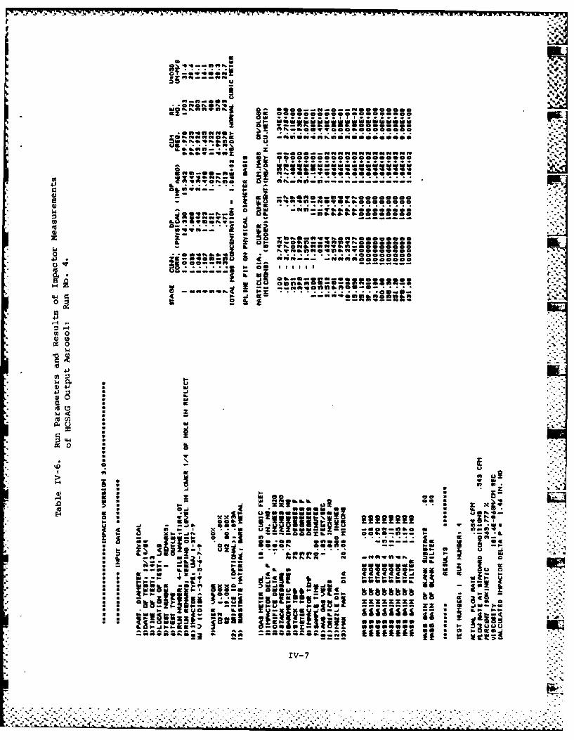
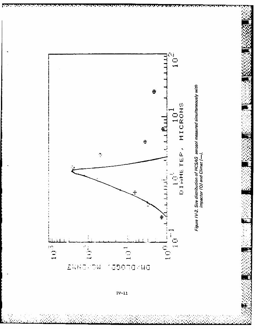
B.. Impactor Run Parameters and Results .... . . . . IV-lC. Climet Results .. ...... . .. .0. . .. IV-l
V. Operating Instructions... . . . . . . . . . . . . V-1A.* Precautions . . . .. ...... . . . . V-1B . Preparation .. . . . . . . . . . . . . . . V-1C. Initiating Operation .... ... . . . .v-2
D. Continued Operation. .# . . . . . . . . . . V-3E. Halting Operation..... . . . . . . . . . . . . v-3
VI. Maintenance . . . .... # . . . . . . . . . . . . . VI-lA.* Drain Bottles .. .. ...... . . . . . . . VI-lB. orientation of Components .... . . . . . . . . . VI-lC. High Values of APACand APAS . . . .. .. .. . . VI-l
VII. Extending Performance .... * .. .. . . . . . . VII-lA.* Other Liquids ... . . . . . . . . . . . . . VII-lB. Increasing Concentration of Output Aerosol ... . . VII-l
VIII. References....... .. . . . . . . . VIII-l
Appendices
A. Drawings of Noncommercial Components .. .. ........ A-1B. Maintenance Instructions and material Properties
of Purchased Components . .. .. .. ... . . . . . . B-1
Aeces~lon For
NTIS GRA&IDTI- TAR
mDitribut ion/
Availrcbilty Codes'Avil and/or
*:.. .. .~ .. .' .* ... .. .* -. .*.*... ...

I. Introduction
For aerosol research and testing it is important to have aerosols avail-able with known and controllable properties. Particle si e distribution isalways an important parameter; frequently, a narrow size *stribution isneeded. For many investigations high concentration is the jor consideration;sometimes this is coupled with the need for high flowrates. nder thiscontract Southern Research Institute (SoRI) has developed the High Concentra-tion Standard Aerosol Generator (HCSAG) system with novel and frequently neededcapabilities: high concentration, high flowrate, narrow size distribution, andparticle size greater than 1 micron
To create uniformly sized particles the generation mechanism must be verystrictly controlled. To obtain a monodisperse aerosol by mechanical agitationsuch techniques as the vibrating orifice or oscillating reed are utilized. Aliquid jet is segmented at regular intervals to produce droplets of the samevolume. For each jet velocity anddiameter the frequency of agitation must betuned very accurately to prevent the formation of multiple sizes. The genera-tion rate is limited to the order of 105 per second.1'2 To obtain a mono- .disperse aerosol by condensation techniques, the thermodynamic properties of '
the flowstream must be maintained within in a narrow range while the aerosol isbeing cooled. This requirement is increasingly difficult to achieve as thedesired particle rate (the product of concentration and flowrate) and particlesize increase. Available generators of this type have low flowrates and arepractically limited to small sizes.
3' 4
An alternate approach for obtaining a narrow size distribution is to use apolydisperse aerosol generator followed by devices which separate the desiredparticle size from the larger and smaller sizes. This is the approach uponwhich the HCSAG is based. Classical impactors are used to separate the largeparticles from an aerosol stream and virtual impactors are used to remove the .:
small particles. -
This report describes the development of the HCSAG and serves as theinstrument manual for the instrument. Section II (Operating Principle) givesthe design criteria as well as describing the basic mechanisms upon which theHCSAG is based. Section III (Description of HCSAG) describes the actualcomponents. Section IV (Performance Evaluation) presents aerosol data obtainedduring the course of developing the instrument. Section V (Operating Instruc-tions) gives procedures for operating the HCSAG and Section VI (Maintenance)describes the procedures recommended to keep the components in good workingcondition. Section VII (Recommendations for Extending Performance) suggestsprocedures by which the system output could be modified to be more appropriatefor given circumstances. These modifications include 1) increasing the concen-tration (if a lower flow or a wider size distribution is acceptable and 2)precautions and suggestions for use of different aerosol materials. Additional .-.
details of the system (including shop drawings, '1i4t lists of materials, andmaintenance of commercially available components) are given in Appendices A and i1;B and are referred to in the text of this report.
I-I - :
.- o.
Since several components and operating parameters of this system representextensions of the technology, significant effort has gone into reporting andanalyzing data in a general form to promote understanding of the mechanismsinvolved.
1-2
A... .-

II. Operating Principle
A. Design Criteria
The design criteria for the system required that aerosol produced by theHCSAG have a narrow size distribution in the range of 1 to 3 microns and thatthe concentration be high enough at a flowrate as high as 140 1pm to producesignificant reduction in the transmittance of visible light over a 4 meterpathlength. The transmittance criterion corresponds to a concentration of atleast 104 particles per cm3 for a particle diameter of 2 microns.
B. General Description of System
Figure II-1 gives a block diagram of the fundamental components of thesystem. Compressed air feeds about 425 slpm (QGEN) to a polydisperse aerosolgenerator (PAG) consisting of 6 Laskin nozzles. Aerosol from the PAG passesthrough two virtual impactors (VPl and VP2) to the primary device (VP3) forremoval of the small size fraction. The major purpose of VPl and VP2 is toconcentrate the primary aerosol stream by reducing the volume flowrate without '-
discarding a proportionate fraction of the particles of interest. The flowsplit in both VPI and VP2 is 10% so that 4 slpm exits through the token flow
Q2T of VP2. A venturi is utilized to accurately adjust and monitor Q2T"
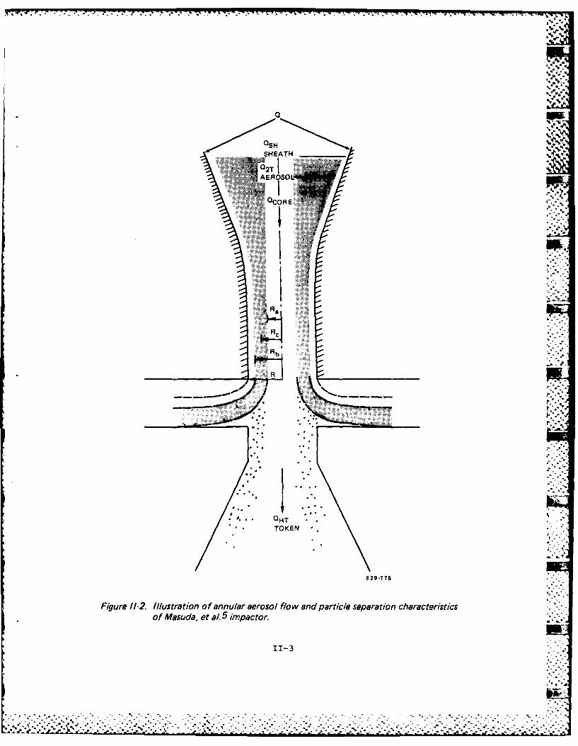
VP3 is a novel virtual impactor in which a core of clean air, ORE isintroduced at the center of the aerosol stream before entering the impactorjet 5, illustrated in Figure 11-2. All of the token flow, Q3T' is comprised ofair from this clean core. Only particles with inertia large enough to pene-trate into this token flow are thus retained. Retention of small particles inthe primary aerosol stream, Q3T' is far below that which can be achieved withtraditional virtual impactors. Clean sheath air QSH is also utilized toproduce a sharper retention (or collection) efficiency than would otherwiseoccur5 ; wall losses are probably reduced also. Figure 11-3 presents results ofempirical investigations of both types of virtual impactors. Masuda,et a15
identified limits on the proportions of QZORE' Q2T' and QSH:
Q/Q2T > 1.43 and
oQCRE/Q2T > 0.-8 -I
where Q is the total flowrate. This device, referred to as the Hochrainervirtual impactor after one of its developers and the current supplier, wastested in the original investigation at total flowrates from 5 to 30 1pm.
Referring back to Figure II-1, upon exiting VP3 the aerosol stream
(Q3T-3 Ipm) enters the outlet impactor (OP) for removal of the large particles.OP is a classical impactor except that sheath air is added prior to the jet tomaintain the desired size cut and reduce wall losses. The primary aerosolstream exits the system through a pressure let-down orifice (PLDO). This
component is necessary because of the significant pressure head across thesystem which is necessary to establish the desired cutpoints around 1.5 jm.
11-I-'9

AEROSOLOUTPUT
Gout
PRESSURELET-DOWN PLOORIFICE
SHEATH AIR -
IMPACTOR O
QHT
HOCHRAINERVIRTUAL ('HO
CLASSICAL VIRTUAL IMPACTORIMPACTORS
VENTURI
-I..'
vP1~~ ------ ****QS
DUMP SMALLSIZE FRACTIONS
POLY DISPERSEPAG AEROSOL
GENERATOR
Ogen
5335-2
Figure 1I-. Block diagram of HCSA G.
11-2
QSH
AEROSOL
RE
........ .
R ~
R
R.. Hb OE
R2-7
.-......................
J.**'*. ....vTOKEN...............................~0:.-
-- I~.-.~.--.->..-.%.-..-.- 0-775.'*

-
0.90-
0.80 /
~0.70 /5. /U.O6 -- CONNER EXPERIMENT 6
0 0.0 TOKEN/0 1N LET -0.0250.50*
/U MASUDA. 5
0.40 0 EXPERIMENT
0.3- /0HT/ 0 = 0.10 /0 2T -
0.2- ,/CORE/ 0 2T =1.4
p ~~~~0.1 103'2-7
FO
Figure 11-3. Efficiency of virtual impac tars versus V .See Figure 11-2. for explanation of Q's.Afte Coner6and Masuda, et al.5
11-4
. . . . . .

.L-
III. Detailed Description of HCSAG
In this section the HCSAG is described in further detail using drawings
and photographs so that the user can identify the actual components, theirfunction, and the valves and meters for adjustment and monitoring of operation.Appendix A (Shop Drawings of Noncommercial Components) and Appendix B(Maintenance Instructions of Commercially Available Components) give additionalinformation. Figure III-1 is a schematic drawing of the HCSAG. Figures 111-2through III-11 are photographs showing various views of the system. Figure ..111-12 is an assembly drawing of the Hochrainer impactor.
A. Air and Liquid Supply
In Figure III-1 the user's air supply is connected to the main pressureregulator indicated in the upper left of the schematic. To keep system perfor-
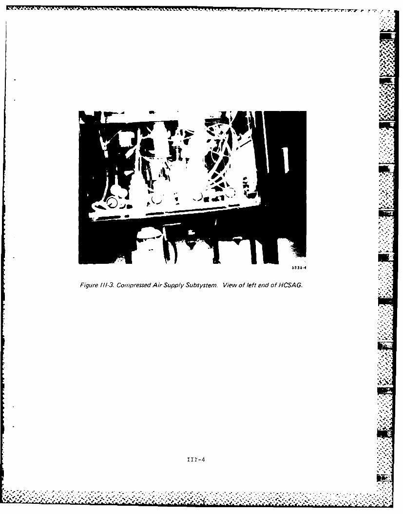
mance constant, the air supply should be capable of providing 25 scfm at 90PSIG (and not more than 150 PSIG) with 10 PSI or less variation. This main airsupply fitting is located just below the left corner of the front panel, shownin Figure 111-2. From this regulator air passes through 2 additional oil trapsand two 12 inch filter canisters in parallel. After these filters, the airsupply branches to 6 paths, each with its own regulator,to the points where airis required by the system. The main inlet regulator is normally set at 60 PSIG
using the gauge located on the upper left corner of the front panel, while theothers are set at 45 PSIG (except for Poil ) . Most of this air supplysubsystem, shown in Figure 111-3, is located at the left end of the HCSAG.
The liquid supply subsystem is located toward the right rear corner (seeFigure 111-4). The path of the liquid in this sybsystem is shown in Figure
III-1 as "solid" tubing. As shown schematically in Figure 111-1, 3 reservoirs(1, 2, and 3) in addition to the polydisperse aerosol generator (PAG) canisterare utilized. The aerosol liquid (DuoSeal Vacuum Pump Oil at this time) ispoured into the top (No. 1) reservoir at the fill tube. Opening the valveunder reservoir No. 1 allows liquid to flow into reservoir No. 3 which feedsthe PAG. Compressed air at pressure Pol is utilized to augment gravity flow
in transferring liquid to the PAG. This pressure regulator is located at thebottom right of the front panel where it can be adjusted to keep the oil levelconstant as viewed through the site glass adjacent to it. Once that setting isestablished APoiI (measured at the gauge adjacent to the site glass) is anaccurate parameter for reproducing a desired fluid level. Overflow fromreservoir No. 3 flows to reservoir No. 2 until the levels in reservoirs No. 2and 3 equalize. Then reservoir No. 2 is emptied by pumping liquid back toreservoir No. 1 via the hand operated peristaltic pump.
B. Polydisperse Aerosol Generator
Air to PAG is controlled at the top right of the front panel (see Figure
111-2) by a ball valve. The pressure upstream of the 6x4 Laskin nozzles(PGJETS) and in the cannister (PGEN) are monitored at the front panel below theball valve. The flowrate through the nozzles is given by
QGJETS= 2.55 (PGJETS+PBAR)n (1)
-.. _-. .

00
LUQ
cr ui
CL -10
CL m <
U) <
c0"'
00

~~oQt
I N
pL"
100
00, U
IT -, -
101
N
5336-4
Figure /11-3. Compressed Air Supply Subsystem. View of left end of HCSA G.
111-4

oa.4
Figure 111-4. Liquid Supply Subsystem. View of right end of HCSAG. Also showscoalescing filters for exhausting 0 10and 02D.
.
111-5

-- _- -r 'W irw~ -v -, - -. - -- , . ! ~ gy
Ob...6 0.0 i 0r
* UL
11 5'.
5335-6
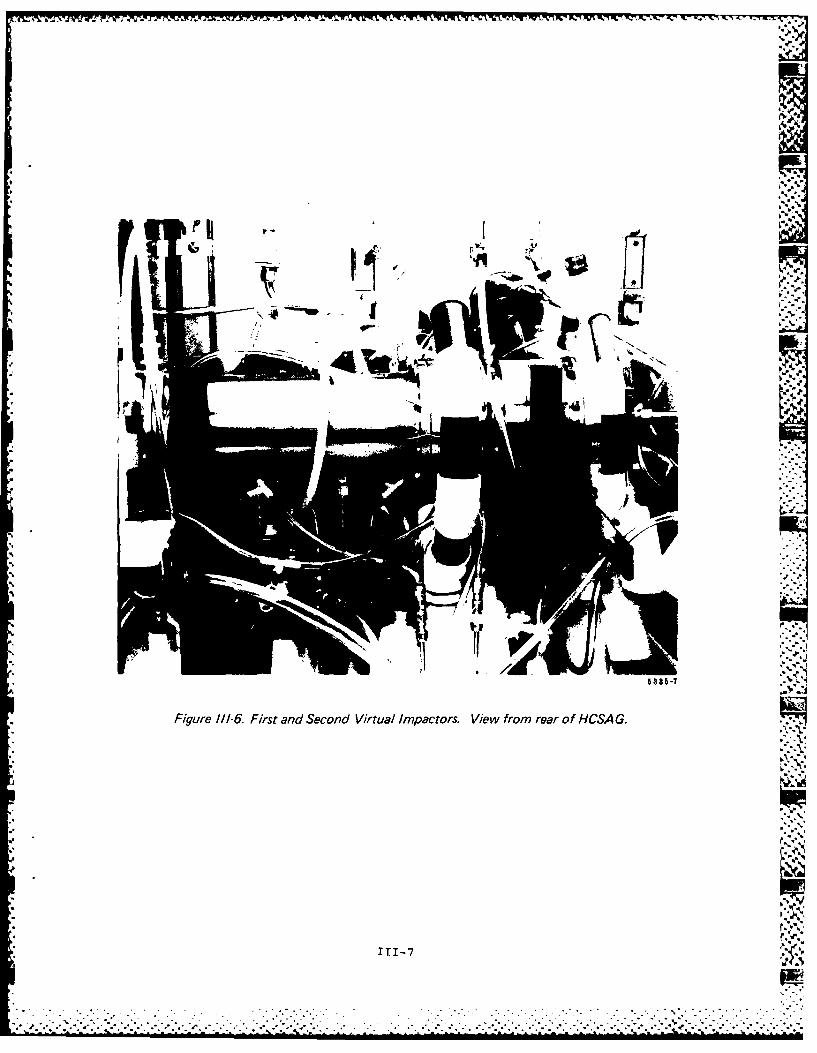
Figure 111-5. Polydisperse Aerosol Generator and First Virtual Impactor (above). View fromrear of HCSA G.
T T T - C
111-

1L.*
Oet.Viwfomlf ra f CA.
111-
CRT-4
V.
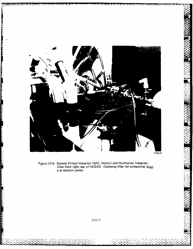
Figure l//-8. Second Virtual Impactor (left), Venturi and Hochrainer Impactor.View from right rear of HCSA G. Coalesing filter for exhausting OHOis at bottom center.

.~.. ..4-S.
'S
I -%
1r
m 4.. '..w iJ~iIq
-. 4--.1*
4 ~ 4..,.
Figure 111-9 Exit from Second Virtual Impactor, Venturi,, and Hochrainer Impactor.4 View from left end of HCSA G.
* '4
~ .'1.
4
* '4
4 ?
4
111-2.0
. . ........................ 4.....4...-.- -. .- -. -. -4.. -- 4.................................................
..........** ~ ~

ifr
, Ib
Figure 1//- 10. Hochrainer Imnpactor (right) and Outlet Impactor (1eft. View fromleft end of HCSA G.
ITI-11

OFF

1,3. CLEAN AIR ENTRANCE2. AEROSOL ENTRANCE4. JET5. NOZZLE6. SUCTION TUBE7. CONNECTION TUBE8. NOZZLE GAP ADJUSTMENT
SCREW I
10. CLEAN AIR LAMINARFLOW RINGS
11. AEROSOL LAMINARFLOW RINGS
12. PRESSURE TAP
P.
(9)C
(4)
A(5)
(6)
(7)b335-1
F, gu re 1-2. Hochrainer Impactor
:11-13

U~~ s W 0..,
AP2 can also be monitored on the front panel for diagnostic purposes. It maybe desirable to use this parameter to set and monitor the token flow of VP2(the aerosol flowrate to VP3). If this is practical, the venturi would not benecessary and could be removed. Additional investigation of the behavior ofAP2T would be needed to verify its usefulness as a flow monitor. Pressurefluctuations in this token flow due to turbulence are of concern.
D. Hochrainer Virtual Impactor t>
The token flow of VP2 passes through a venturi which provides an accurate Flu--determination of flowrate:
Q2T= 0.8 3 APV /(P3+PBAR) (5)
for Q2T in alpm, APv (pressure drop across the venturi) in inches of water, T
in *R, P3 (pressure at the inlet to VP3) in PSIG and PBAR in PSIA. APV and P3are monitored by gauges on the front panel, near the center. The venturi isshown at the center of Figure II-11 with VP2 to the left and VP3 to the right.The aerosol stream is merged with two other flows QCORE and QSH in theHochrainer impactor as described in Section IIB. An assembly drawing of thisdevice is given in Figure 111-12 with the major dimensions. Figures 111-8 and111-9 are photographs of the actual device. QCORE and QSH are monitored byrotameters at the top center of the front panel. The readings from thesemeters must be corrected by
QCORE or QSH = QR /(P 3 + PBAR )/14 .7 (6)
for flowrate in slpm where QR is the reading of the rotameter. To convert thisflow to actual volume flowrate at the jet of VP3:
QCORE or QSH = QR (6a) -
where QCORE and QSH are in alpm. The flowrate through the jet of VP3 is givenby
Q3 = 0.61AP 3T/(P 3 +PBA (7)
for Q in alpm (upstream conditions), AP3 in inches of water, P3 in PSIG, andPBAR in PSIA. A meter giving AP3 is located on the front panel directly abovethe P3 meter.
A meter (&PAC) at the bottom of the front panel, under the APv meter, isused to monitor the pressure drops across the laminar flow rings (No. 11 inFigure 111-12). The holes in these rings can become covered with liquid due towall losses. APAC may be used to diagnose obstruction of flow by liquid.Under normal conditions APAc oscillates between ±0.2"H 20. Cotton threads toserve as a wick were added to the base of these rings to reduce the buildup ofliquid. The wick extends into the drain bottle for this region. Care shouldbe exercised not to pull on this wick when emptying the drain bottle.
III-1 5-[""
; . • . ." . .. '.'.'..- . .. ".. -°°'...'............'.....................-..-..-.•......................."................... . ..........
77 7 7-'-. 77777, T-.
,.
Because of the potential of liquid drops collecting on the entrance tothe jet of VP3, the user is cautioned to avoid operating the system without
QCORE and QSH flow. Most of the flow of VP3 is exhausted through a coalescingfilter, a metering valve, and a rotameter. The valve and rotameter are locatedon the front panel just left of center. This valve is important for adjustingthe flow split between the exhausted air, Q. and the token flow, QHT" The
rotameter gives QHD in slpm; it can be converted to alpm at the conditions ofthe inlet of VP3 by
QHD= QR 26.6/(P +P (8)
where QR is the rotameter value. The primary aerosol (without the smallfraction) passes into the token flow of VP3. This flowrate QHT is determined
by the difference (Q3 - QHD ) " The pressure differential, APHT , between thetoken flow and inlet to the jet of VP3 is also metered on the front panel fordiagnostic use. This meter is located between the rotameter and control valve .for QHD. As with AP2Tthis parameter is expected to be proportional to thetoken flow QHD However additional investigation of its behavior, beyond thescope of this project, will be needed to verify its use as a monitor of QHT"
E. Outlet Impactor
The token flow of VP3 is merged with a sheath of clean air in the outletimpactor (OP) shown in schematically in Figure III-1 and in the photographs ofFigures III-10 and III-11. This sheath air flowrate Q, is monitored by arotameter at the top left of the front panel. The reading on this rotametermust be corrected by
QI= QR (9)
for flowrate in slpm and by
QI= QR 14 7/(PI+P (9a)
for flowrate in alpm where QR is the rotameter reading and P1 is the pressureat the inlet to OP in PSIG. The meter giving PI is located below the Q,rotameter. Q, is set at a value for which OP will remove the large sizefraction. In principle the exact value depends upon the trade-off between thedesired width of the distribution versus the desired particle rate. However
the size distribution of particles from the Virtis SG-40 polydisperse aerosolgenerator with DuoSeal Vacuum Pump oil, drops off sharply at about 211m soadjustment of Q, has little effect on the output. Of course if Q, is too highthe desired particle sizes would be impacted. Varying Q, affects P1 whichaffects the flow split in VP3. Thus QHD must be adjusted appropriately tomaintain a constant token flowrate QHT" The most important priority inadjusting Q, is to provide the flowrate needed to maintain the pressure (PI)necessary for suitable flow split of the virtual impactors throughout theHCSAG. This pressure is determined by the pressure drop occurring across theOP jet and the pressure let-down orifice PLDO at the HCSAG outlet (see Figure . .III-11). The desired flowrate, QI, can be modified by changing the diameter
of the PLDO. Two sizes (1/16" and 3/32") are supplied as accessories.
111-16
,: .- .9

Wire screens are used as diffusers to evenly distribute the sheath airflow, QI, prior to merging with the aerosol stream, AHT" with APAC, thepressure differential (APAs) between the token flow and the sheath flow ismonitored to indicate obstructions of the sheath air flow due to liquid buildup on these screens. This meter is located at bottom left of the front panel.The user is cautioned against operating the system without some sheath air tominimize the deposit of drops on the entrance cone of the VP3 jet.
The pressure drop across the jet of OP, API, is monitored on the frontpanel at the upper left between the Q, rotameter and the P3 gauge. Theflowrate through this jet is given by
+ QHT = 2.9 VAPIT/(PI+PBAR) (10)
where Q, and QHT are in alpm and API is in inches of water.
F. Oil Drainage
As shown in Figures III-1 through III-11, a substantial part of the HCSAGhardware is designed to drain liquid collected on the walls away from theflowstreams. These losses are undesirable but unavoidable. Continuous opera-tion of the HCSAG at conditions described in Section IV for 8 hours indicates , .that the current drainage system is adequate. Accumulation of liquid is veryslow in all drain bottles except for the one which receives liquid collectedfrom the inlet chamber of VPI. This bottle is located beside the PAG canisterat the right end of the HCSAG, easily accessible for emptying.
111-17
rE

- 1 01 -1 -1 7 0, 01 -C, 11
4-4~
4 ~
tW i, .11 003 0 0 OMS CC V*SOCV
I -. 000 00 0g! 00C!9
00
00
9 MM 9C 9 1CW 9 C 9 9
IV-
C C.t . - -
~'%4
4.* A.4%-4.*.~*B.'.
* 8~*-a
a.
Table IV-2. Stage Configuration of EM Mark V Impactorf or Measurement of HCSAG Output Aerosol. rIt
- a ' -
- - -- - -f
- C "a. *-'-- - -
-. - 4-':* - -
- ------ I 4 - - -, - - . - - -
.4. 4..
4.
L
'4%
N
-. 4.'
4.'a'.
IV- 3
4--'
C.--- - - -

m* M-
A ft P,00ft0 t4U0
Z3U *ooo@oo0000??000 o?00
d!-- . V! V!_o even .. .. .f! 0 1 !q!C ! !C
* - S, ... ................vD vv ftwo! ! ! !o!
- 00001!, 000 00V0............... .
1% 0 . .m m m - q q v" -".. o6.. . £ .. *oooom o M.m.
S5 66. . .OOeO O".
P. :
L M 0 .,4UI:M 5.-.U:000
o . S*.........0000
04 -- - - - - - - - - - - - - - - --
'44
I--I
""4-4 "*S
0 U"
StoUW
-S Ow -,4! I
on 00ILmum~ 1!!!!!! : N~
C, w j W MW IW"
oW a5 £5 *Mae~.~MDS5. m O~e S-A
i: - I a w*~u S. gas&&&&M UX0.
* a -- 15 -suail Ali;*~~EC 02 U 54 U L-1 1£ MI
iv-4. -I
I.%%~
C~in
*vvftWgv.._ iEdftq!!CC
so [email protected] Wt 0a00m@000
urn 1!- %
.. umu jruu mu 1 mV
4j .~ . -.. ft~mS1-e-6'6 IL -n*.W&&Oqqqoqq.#e
In$4fttttfff
a. 6. am I II
4,*0tNI tt~f~t0~0O@0
() C4.4 .. .. . . . .. .. 00 0-
40 91-flu ' ~ ~ ~ .0 22--------ttlooexoo
4.4 u0* .0 61
4.J
.41
41
It ...
u wa t Nn-iU
.4.1J " 916 :Ic 1s 0 - l "4 ;a40,. 0000(
01r uW -0
IL v I a..
: 104 -"t e rS* if
HIS
86- 9 1. -rp 2 0-04
oilf
== U Un--f u fm
~..45 u-5

wPf waf-@0q!!!444
R *.. ..... ..I .... *...
. .~.6 .. .Z
cc . . . . . .. . U
* --
.... ~ 00000000
mooq'oooe@
o 4
x. 0
* 1
9c I*
aa
ix av0
I-0 a
Q J
Ob. W . ft0
- K
id b. Iot a
* U bU sm WU we SI ~* ~ rlg SKU 1 .- !M. K.
32 W-WA 0S0-l "IN Inb.b a1US 0-94U03 K I - >.
I0 0 0 . 1 b -I
.- a -; Kb.-' 0 we uu*t 09 a..~ a- a0 I-W 2-- *U feeZZZ 1111 ff IMJ
IV-6
XI;
W&Nqft.~q 49 1
.............. ~
V) qp in a Pn, v P.O~
o t on~U S
lag~te~mm**0%~O-..4mgq2 mm mmex
44r e 4 # U) m m ~ m0 WOE~ ee mo m
41 IL
(a cn
:> 0' . 0 V fz @ . - ~ Z ZIti
paaaaaaaaaaaaaaaaaaaaaaaaaaaaaaaaaaaaaaaaaaaaaaaaaaaaaaa,
U,amre.. . cc 0-
.................................
* -. - ~ . . - . ... . ... . . . .
oo Nv4q .0.0000000
lo -" f- - S AC00000I
Ln0
ifZ-i m ewo e @ @ @ @ .
06 1106 e e @@ o ee e
a as
E-4-
IRV ..u,0 ioim;a: , &a aa a 000
N tqe.r.. -
0~~~~~ a.E ww: ; : : u
-E m. a; ,.b.et
HIM _2 Lv
SSaAS -
r 35
-. 4..
-4..8

C)~
IV'-4
k-I
IV-11

V. operating Instructions
These instructions assume that the reader is familiar with the HCSAG andthe nomenclature and figures of Section III. For illustrative purposes it isassumed that the conditions or operating parameters of Table IV-1 are to beachieved. It is assumed that a compressed air supply and shut-off valve hasbeen connected to the main inlet to the HCSAG at the lower left corner near thefront panel. Keep this shut-off valve closed until preparatory steps describedbelow are achieved.
*A. Precautions
The most important precaution is that no parts of the system downstream ofpressure regulators and control valves be pressurized at more than 16PS 1G. This means that all pressure meters on the front panel should bekept below 16 PSIG except PGET and PMI'If the outlets of the systemare closed off for any reason then these two gauges cannot exceed 16 PSIG.Thus some care should be exercised to turn the main pressure regulator,
PMAIN' on slowly while watching the pressure gauges on the front panel.
B. Preparation
1. The drain bottles for the inlet chamber to VP1 and for the coalescingfilters on Q1D and Q2D should be emptied. They are located at theright end of the system beside the PAG canister. (Emptying of theother bottles is discussed in the next section on Maintenance.)
2. The oil in the lower reservoir (No. 2) should be pumped up to theupper reservoir. Check the level in the upper reservoir to determine .
if liquid should be added. The systen uses about one inch per hour. U
Oil is added by disconnecting the tygon tubing leading from theperistaltic pump to the top reservoir. The joint between the curvedtube and the elbow fitting at the top of reservoir No. 1 (see Figure111-4) is convenient.
3. Check the level of liquid in reservoir No. 3. It should be at or nearthe top of the overflow tube. If it is not then open the controlvalve (several turns) at the bottom of the top reservoir (No. 1) toallow liquid to transfer.
4. Check the liquid level in the site glass on the front panel. Liquidshould be visible but not higher than 2/3 of the distance from thebottom of the site glass to the hole at the center of the reflector.If the level is too high then carry out the following steps:
- close the aerosol generator valve,- turn the Poil regulator to zero (counter clockwise until the knob is
loose),- open the connection normally used for putting liquid into the top
reservoir,
V-1

- open the exhaust rotameter valve, if it is connected,- turn the main regulator to zero,
- turn the air supply on,- close the valve on the Qadd rotameter until liquid in the PAG startsflowing into reservoir No. 3. This can be seen by looking at theliquid line between these two components,
- if nothing happens check the regulator for the Qadd line and open itif it is not already open,
- when the level in the site glass drops below the appropriate height,turn off the Qadd valve and turn off the PMAIN regulator,
- reconnect the liquid line at the top of reservoir No. 1.
5. It is very helpful to have an optical particle counter ready to samplefrom the HCSAG output to optimize final adjustments based on theoutput size distribution and concentration.
6. If the operating conditions from the last usage of the system werenormal and no valves have been changed, then open the shut-off valve
of the compressed air supply and proceed to "Initiating Operation"below. If the position of the controls are uncertain then perform the
following steps:
- close all valves on the front panel except QID' Q2D' and QHD (whichshould be open) and turn all pressure regulators to zero (counterclockwise until loose),open the shut-off valve controlling the compressed air supply,
- turn the PMAIN regulator to 50 PSIG and turn all other regulators to45 PSIG, except for the Poil! d JETS regulators; Poil shouldremain at zero while PGJETS should be adjusted to 35 PSIG,
- turn PMAIN to 60 PSIG,- adjust Qcore' QSH' and Q, to about 20, 5, and 40 PSIG, respectively. :. J
C. Initiating Operation
With PMAIN at 60 PSIG and Qcore' QSH' and Q, at about 20, 5, and 40 PSIG,respectively, open the ball valve on the front panel controlling the PAG(full open). The immediately adjust the Poil regulator to about 10" H2 0,returning to readjust it while adjustments of other valves are being
operformed. At this time PGJETS' PGEN' Pit API' P2 ' and AP should be nearthe values given in Table IV-1. If not, then review the steps to thispoint and check the system for abnormal signs.
Adjustments to achieve the appropriate values of the other parametersrequire an iterative approach. Q2D' core' QSH' QHD, and Q, are relativelyinsensitive to the others so adjust those first. This should cause P 3 ?AP3 ' P' and API to be near the appropriate values. If not, readjust those
valves. It is important to be familiar with the plumbing or have FigureIII-1 at hand and to keep in mind that the appropriate values of Q2T and
QHT are attained when near balance pressures exist. Next, slightly adjust"Q2D' ore' and QSH to obtain the appropriate value of APv. Small devia-tions of Q2D do not effect the output. Set points of Pv' QCore' and QSH
V-2
-------------------------------... .... . .. . .. . .
. . . . . . .
yV r-w _i- _ wb VV -I. 4 J' r W.. V~ pV -,- J,- VFWLf.V1V V" ~ .
are more important. Finally, adjust Q. and QI to obtain a positive APHTin the given range.
Next, review the meters for a value that deviates by more than 5% from theappropriate value, excluding APHT" If a larger deviation is found repeatthe adjustment procedure starting with Q2D' Qcore' QSH, QHD, and QI.
Perform final adjustments of Q, and QHD optimizing the output distribution ,m'measured with an optical particle counter, if available.
'• .Adjust Poil to establish and keep the level in the site glass at the loweredge of the hole in the center of the reflector.
D. Continued Operation
Once the adjustments described above are performed, long-term operationcan be expected. The drain bottles should be checked and the liquid levelin the PAG adjusted as needed. The system has not gone through extensivetesting needed to establish a APoil for an absolutely constant liquidlevel.
E. Halting Operation
When operation is completed the only step necessary for the HCSAG is toclose the compressed air supply shut-off valve or turn the PMAIN regulatorto zero. If all other valves are left in the same position then adjust-ments are not needed in the next period of operation except for APoil*The operator will likely wish to adjust it to reestablish the appropriateliquid level in the PAG.
v-3
.. - . -> . .? .:-*
VI. Maintenance
A. Drain Bottles
Some of the drain bottles have an air relief tube on the side of thebottle as well as a tube for liquid to enter through the cap. One of thetubes must be disconnected from the system to twist the cap or the bottle.For three of the bottles the tube that is disconnected must be the airrelief tube so that wicks will not be disturbed, potentially disruptingproper operation of the system.
One of the bottles that is connected to the union cross fitting justupstream of the venturi is shown in Figure 111-9. A wick made of blottingpaper extends along the lower wall of the token flow tube from VP2 to theunion cross and down in the bottom leg to which the bottle is attached.Care should be exercised to refrain from rotating this cross or the bottlecaps, thus tearing the wick. The top leg of the union cross can bedisconnected to permit turning of the bottle while holding the cap steady.Only one full turn is necessary.
The second bottle of concern is the one which catches liquid drained fromthe entrance to VP3. A safe way to remove this bottle for emptying wouldbe to detach the air relief tube at the side of the bottle. Then thebottle can be turned while holding the cap and wick steady. A suitableloose clamp must be used to resecure the air relief tube to the side ofthe bottle.
The third bottle of concern is that catching liquid drained from the unioncross in the token flow, QHT' of VP3. This cross has a wick extend backto VP3 like the one upstream of the venturi. The top leg of this crosscan also be disconnected to permit turning of the bottle while holding thecap steady. Care must be exercised to refrain from rotating the unioncross.
B. Orientation of Components
The orientation of components relative to the horizontal plane is alsoimportant for drainage. The VP1-VP2 unit should be tilted slightly risingtoward the downstream direction. The venturi should be in the horizontalplane. The VP3 and OP components should bp essentially horizontal, risingslightly toward downstream rather than the opposite.
C. High Values of APAc and APAS
If APAc or APAs rise with use to high values then their respective flowsare being obstructed, probably by liquid in laminar flow rings or screens.It is possible that this symptom can be eliminated by drainage givenseveral days without operation. High flowrates of clean air in thereverse direction through these elements would augment the drainageprocess.
VI-1
. . . . .. .. . . , .. . ., , . . . . . - -., . - .--..
VII. Extending Performance
A. Other Liquids
If it is desired to use liquids other than the DuoSeal Vacuum Pump Oil inthe HCSAG, several factors need to be checked to verify the feasibility.Appendix B gives physical and chemical properties of nonmetalic materials used ,Vin the system. Metal parts are made of aluminum, nickel plated brass, andstainless steel. If the user is uncertain after considering resistance ofthese materials to the liquid of interest, it is suggested that tests beperformed exposing samples of the materials to the liquid. In addition tosigns of corrosion, check for softening, swelling, or shrinking of plastic
materials.
In addition to material problems, many liquids are extremely flammable orexplosive when aerosolized. This can be checked by putting a small amount intoa nebulizer and routing the aerosol stream through small tubing. If theaerosol exiting the tubing can be ignited, it will be hazardous to use in theHCSAG.
B. Increasing Concentration of Output Aerosol
Wall losses could probably be reduced in the system giving higher outputconcentrations by increasing the number of jets in VP1 and VP2. This redesignwould decrease the pressures needed throughout the system eliminating thatneeded for the pressure letdown orifice PLDO and reducing the turbulence in thesystem.
.4.4-
vII-1
'S'°,'
I,°
.........................................

VIII. References
F,..
1. Berglund, R. N. and B. Y. H. Liu. "Generation of Monodisperse Aerosol
Standards," Env. Sci. Tech., 7(2): 147-153, 1973.
2. Service Manual - IBM Office System 6 Ink Jet Printer 500. InternationalBusiness Machines Corporation Form No. 241-6201-0.
3. Liu, B. Y. N., K. T. Whitby, and H. H. S. Yu. A Condensation AerosolGenerator for Producing Monodispersed Aerosols in the Size Range 0.036 to1.3 Microns. J. de Recherches Atmospheriques, pp. 397-406, 1966.
4. Particle Technology Instruments. Thermo Systems Incorporated, St. Paul,MN. Form No. TSI 3000-R681 8M-2MBRI.
5. Masuda, H., D. Hochrainer, and W. Stober. An Improved Virtual Impactor
for Particle Classification and Generation of Test Aerosols with NarrowSize Distribution. J. Aerosol Sci., 10: 275-287, 1978.
6. Conner, W. D., "An Inertial-Type Particle Separator for Collecting LargeSamples," J. Air Poll. Contr., 16(l):35-39, 1965.
VIII-1
z.,.-. . . .. .. . .. . . . . . .. . . . . . . . . . . s -
. . . . . . . . . . . . . . . . . .. . . . . . . . . . . . . . . .
W.-
Appendix A Drawings of Noncommercial Components
A-1
. . . . .. ...
ISI
A-2-

1.A
.z -Z
<I1 -
4- 47-
4 r
- t--
0 * A-3

e. .~
'I!
, O.~3jQ~ ZI £
- p -k--,- ~ ." -.
'7 .
& ~x~aa /
-~ "b.
II-~ '-N ______ 1* ~ -.---- o-~ 0
4 A// Ii
\ \ -
\ .i" /
-- '-ti .- ~ ~
0
- - / ---- t------~~~ -~-- 0
'-xJ
I, r / ~
7.-'
~---~ 7I 7
~ ' I-o ®-~-* '4.--------,-. -~
-- K P-'~ '- b~h~
'-7 ~ /1
\-~ 7~iK~ 7-v~ 0- /--
-~ II~II
I
A-4 w

*
6
* . . C.
* ~'~.***?' 7
~ VU~
~ . ~
~
U~~7% ~ .' - . 2 .- ~ ~.
.
* .
.1
1%
*
Ii~
*
I-
ut,; ~
*
0
~*..* ~*
U."
* .
~..
K
.1'
b ~
~ 'II
A ~
I-
N
~
-'-.r-'-~
-
_
~1..t.
a
4Z'
4-
'N .
i
//
' ~ ~
V
0 -
-&-~.
Ij~aj~
,0
4--
~~oo ~
S
Z~*-
-.
* - t
a.
A-Sa *P~.-N.
C..
.1 - -A P
IIJJ .N
* . . ft .
i I , *.-
o ._ J.'.,-
I :
, x;7;';;
/ - " "
"* . . ." " " '#" . .." " * 'I " - ~ ' " ,' , - .. - " .' o. *.- - - • . *. ." "}. .'. .* . ' - -. . '. AZ .<__ _"-''." .'."..--r_"." ," " "_" --' i*"
"'
" ;4 . ,"- " " ". "," " _ •"/ '"1"." "".- ,-- " • " "' I" ," " " "
IJ
4i-4
A-8

'A-9

090
A-100

- a.. - - a. -- - a b
-w
A a. ~'
4 £ £J.
I~ I;~ - -' w~
I: ~jm 1I~ 40 -A
.. ~ Ii ~ a-. -
-, a
f.- aD.~ -, 13 ~
g juff~ .. -I,
0 ~* ~. 4"
- ill ;.
IF
I Ii . , II- 1 'III
I III jq I
* . - - i~'I *..
I
I
I* i*1 ,.~ I
* II \. i7~7hN\
.-. 0
0/
I~i
I I
(t)o .00
I -
/ :1
~ J J -
.1
I I
A-il
-. - -*.* - - *: -7 -a .- .* . -.................................................
~ '......*.*....J.............................................

. -j~ *~ -~ J" ~, ci * ~
~ ~
*~..* *, ~
~'. *,
.1
- - - - -rna
I- ~
aii ~ I,
i.J.~
~i) ~0 -5%
0~
Sb
~S
~ (j)
- 5%~*
1 '5
j ~ vs~
0
-J
5-
5
a
~.
I",
__
~.K
t~~~,0
H
___
____________
'1
* b
A-12
................................................................................................

.1 a '.k
L I-
el a
i kiI
-k - --------
. °
A-13-
-- "
. ,*. L -..
o* .,. \.
--i _i
7I-
A-13 '."i
- 1 - -------- -- ----- 1
A-114
... - - .. - -. - -. -. - ~ -~ TW~ -
;,.~: ~
'AI
%
-~
'Joi.
I3~
4 -Pu
* r~jI -~
. ~
-~ *'~.p %~
F ___ ___
1
'\. -
tr
-
0
' - (.
I
/
a7
-- -
1
A-i 5
........................................................................................................

-: -.7 ~ ~. ~ ~- .- -,. - - - - -. -V...
* .I~& ;II~
1120-- ~ B
/
I0' '0
A
0'' II7/
*>.~ - - (~)
U
~i ZE
1~~ _____- I
'a
,ad~ -,
I.
-~ b
*.
11 ~. 4
A-i 6

in~ 7
' I
~aA-17

* -- * ,--l
y LjL
7-
MIR.
I~ -. S
1. 0wg.w
x
A-18

no 2V -. lI W r
OL,2.w
C4,
A-19
/-10 FM A7
o.±-3 ,i A
AZ-5 T.Z 14
12- rudE
/ XAC-Voe rtmerr OvEt
SO&DCZ ryp PLAE.S
PL q<2 P~E.5 oP
A- 20

P-
'~ 7' P'F CA ICA.,.S
_________________________________fol*.
OIL.
!4.DIA 7 ~ 'DA. siz rcFo aoz(wi t&s ov )
:)24 II
fil. I

Appendix B Maintenance Instructions and MaterialProperties of Purchased Components
Page
Cole-Parmer: Tygon plastic tubing, silicone tubing, PVC pipe. . . . B-2
Dwyer: Magnehelic Differential Pressure Gauge. . ...... . . B3-8
Dwyer: Rate-Master Variable Area Flowmeter . . . .. .. .. .. . .B-10
Fraunhofer-Institut: Virtual Impactor .. ......... . . .. . .* B-14
Gelman: Acroflow II Filter Cartridge .. . . . . . . ... . . B-27
Sargen-Welch: Duo Seal High Vacuum Pump Oil. .... . . . ... . . B-29
*Sears: Fine Replacement Water Filter Cartridqe . . . . . . . *. . .* B-30
Virtis: SG-40 Smoke Generator. .. ............. ..... B-32 -
B-i

Cole-Parmer Instrument Co.7425 North Oak Park Avenue
* Chicago, Illinois 60648 U.S.A.[a) Tygone (R-3603) pLatic tubingmetal, bonds to small-radius curves to speed set-ups. A long-life tubingtha won't age or oxidize. Autoclavable at 250rF (121T), 15 psi for 30minutes. Transparent Temnp range: - 5(rtW -s15F(45*to +-741C). .
Ib) Silicone tubingFor greate howt resistance and low comnpression sit. thia odores, TUBINGtranslucent tubing is recommended. Excellent biocoinptibility Meets* j FDA, USDA. USP class Vi requirements. Do not use with concentratedsolvents, oils, acids, or dilute NaOH. Autoclavable; remains flexible g) Pol yaiyene tubing* ~~~throughout a wide temperature range: - 60* to + 500PF (- 6? to ~ sn-ume rnlcn.Uafce ymn hnlas x
09111"t electrical insulator. Low water-vapor, pen eabillW, high 02 andC) Beu-a-lne IV tubing COI PerMiablity. Bends eve at low temperature. Temp range: - -I0Saoe up to 50% ame IM tubing. No pa saefor food, bev- to +~ 176T ( - 6(r to +- 80,C).erae. drug, lab, and medicael use. Meet FDA, USDA, Natronal Formul-sty, and USP standards for high-purity systems. Polyethylene, liner with A) Polypropylene tubingety vin" acetate outer shell, tor all the advantages of polyethylene TrsfllC" and more Mglgd Winn polysltwylene tubing. High che.Mcwithout stress-cracking. Heat-bondable: needs no Connectors. sale for al. 3"W and Puncture resi11stal'10. Temp range: + 32' to + 275*F (0r to* alcohols Tmp rag 60W to + i60*F ( - 51* to + 71-C). + 135-C). Nalgene.d) Gum rubber tubing 1) Polyurethane tubingTMh k-fltx tubing. Seamless for lor life. Ideal for liquids and Clow, flexiles Clan; ideall for high-purity work. Excellent chemicalgases. Amber-colored tubing can be stenilized repeatedly Temp range: resistance. Temp range: - 94e to + i irP (- 7(r to + 8?C). Nalgene.- 22?to + 30*F (- 3(rto + ISO)% j) ANorprenes tubinge) Vinyl tubing OzOmmelsantwt for 101ger Ife in electrical environments. Heat.
* ~ ~ TOhug fexil polyiy tubing has excellent clarity Odorless and sealabile, flouaging, flOflOxifng-shows no sign of weakening or* nontoxic. Good water, chemical and abrasion resistance. Temp range: cracking after years Of exposure to heat and ozone. Superior acid and* -40to + 16(F (- 40rto + 8:C). alkali resistance. UL-listed for some applications. Food-grade Norpreneaf) C-FlM thedrm oplastic elastomer tubing is available in quantities; of 1000 feet or more, call or details.
High-pMdoraNIce, lng-life tubing. This durable tubing formulation OpqebakTmprn:-6Wt+27F(-5-to+1-C.Zexhibits exceptional chemical and temperature resistance: surpassesUSP class VI requirements, meets FDA standards. Excellent tensileand tear strength. Smooth surface: low gas permeability and goodbiocompatibility. Sterilizable by ethylene oxide. gamnma radiation, orautoclave. Opaque white. Temp range: - SCI to +- 230rF -62 to
* *.-10'C).C-lIX-TM Concep t n. N-Wpren-Tw Noton Co.
B -2
Aft

A GUIDE TO THE STRUCTURE& PROPERTIES OF RESINS*
Biological properties of plastics Polysulfone (PSF)t10et of the platica used In our platlcware are bIologically Clea, strong, nontoic and virtually unbreakable. Unlike polycar-Insit. P lyethylenes. polypropylene. polymethylpentene, polycarbon- bonate, polysulfone will not hydrolyze during autoclaving and has aate, polystyrene. and Teflon# FEP have been shown to have no effect natural straw-colored cast. PSF is resistant to acids, bases, aqueouson tissu, cultures. Distilled water for preparing culture media can be SOlutions, aliphatic hydrocarbons and alcohols. PSF is composed of,. -
controlled and stored safely in potyettyIene containers. phenylene units linked by three different chemical group-..opropy-...dene. ether and sulfone. Each of the three linkages imparts specificoyprorties to the polymer chemical resistance. temperature resst-
TP0m ein l tnmance and impact strength.Thes resins are break-realistant, nontoxi. noncontominaiting.They are fth only Plastics lighter than water. They easily withstandexposur to nearly all chemicals at room temperature for up to 24
hours. Strong oxidizing agents eventually cause embrittrnent. Allpoiyolellns can be damaged by long exposure to ultraviolet ligh.
Polye hylene.t The polymerization of ethyl-erie results in an essentially straight-chained.high molecular weight hydrocarbon. Branch-ing (side chain formation) occurs to an extent Polystyrene (PS)tand can be controlled. Minimum branchingresults in "high-density" polyethylene e. Rigid, with excellent dimemonal stalilty.(HOPE), also called "linea" polyethylene be- - Polystyrene has good chemical resistance tocause of its closely packed molecular chains. aqueous solutions. This extremely clear ma-
More branching gives a less compact solid known as "low-density" or tetal is commonly used for disposable labo-"conventional" polyethylene (LOPE). In general. HOPE has greater ratory products.chemical resistance than LOPE. and is more ngid. Polyethylene ischemically unreactive: strong oxidizing agents eventually cause some .oxidation: some solvents cause softening or swelling, but no solventis known for polyethylene at room temperature. Polyvinyl chloride (PVC)
Polypropylene (PP)t is similar to polyethyl- Simia In structure to polyethylne, butene. but each unit of the chain has a methyl each unit contains a chlorine atom. The chlo-group attached. It is translucent, autoclav- nne atom renders it vulnerable to some sol-
e able, and has no known solvent at room tern- vents, but also makes it more resistant inperature. it is slightly more suscepoble 1o many apications PVC has extremely goodstrong oxidizing agents than conventional resistance to oils and very low permeabilitypolyethylene because of its many branches to most gases. It is also transparent and has a slight bluish tint.(methyl groups). Narrow-mouth bottles made of PVC are relatively thin-walled and can
Polymethylpentern (PMP or -TPX")" is sim- be flexed slightly. When blended with phthalate ester plasticizers.0 * * lar to polypropylene. but has an isobutyl PVC becomes soft and pliable, ideal for laboratory tubing.
group attached to each unit of the chain in--- 4 • stead of a methyl group. Its chemical resst- Fluorocarbons
ance is closer to that of PP. It is more easly Remarkable chemical resiltance is typical of Teflon* tetrafluoro-softened by some hydrocarbons and chlonn-ated solvents. and strong oxidizing agents ethylene (TFE) and fluonnated ethylene prpylene (FEP).
will attack it over a period of time. Its excel- e Teflon*TFEt is opaque white. Has the lowestlent transparency, rigidity, and chemical me- .--- friction coefficient of any solid. it makes su-sistance, plus its resistance to impact and to . e I perb stopcock and separatory funnel plugs
high temperatures, make PMP a superior matenal for labiware. PMP -. because of its low friction and tight seal.withstands repeated autoclaving. even at 1 50C. It can be used inter-mittently to 1751C. - e Tflon FEPt is flexible, translucent, has a
e FEP slight bluish cast and a heavy feel becauseof its higher density. It resists all known-Polycarbonate (PC)f chemicals except molten alkali metals, elemental fluorine and fluonne
* ~* *Toughest of all them- Precursors at elevated temperatures. It should not be used with con-moplastics, polycarbon- centrated perchloric acid. FEP withstands temperatures from -27( to
__e--.ate is window-clear. .205°C, and may be sterilized repeatedly by all known chemical andamaigly strong and thermal methods. It can even be boiled in nitric acid."-
rigid. autoclavable, and Teflon-& PFA is a plastic with higher mechanical strength at4 non-toxic. Polycarbon- elevated temperatures than TFE or FEP. Maximum continuous ser-
ate is a special type of vice temperature is -500"F (+260"C).polyester in which dihydic phenols are lamedl through carbonate Thflel * ETFE is translucent white and slightly flexible. Similar tolinkages. These linkages are sublect to cfeinica reaction with bases Teflon TFE and FEP. with greater mechanical strength and impactand Concentrated acids. hydrolytic attack at elevated temperatures rin(e.g.. during autoctavng). and make PC soluble in vanous organic resistance.
solvents. The transparency and unusual strength make PC ideal for Hlar, E-CTFE is an alternating copoloymer of ethylene and chloro-high-spee centifuge ware. trifluorethylene. Withstands continous exposure to extreme temps;
.Fl- maintains excellent mechanical properties across this entire range;• o ffl ,. of Y i N o" C o. excellent chemical resistance: radiation resistant.
iCCuIVI AO. Td1 meFodeo ifwi, c o 4du4 9 TM I i du Po do Nwimmn a Co. k" Ae TM AIM Com.
Ptaaaewalm. 1965 B-3 3
% . . .

CHEMICAL"RSISTANCE AND PHYSICALPROPERTIES OF RESINS
Interpreting these charts in sfeigand swelling,.o pereation of solvent through the plasic;Chemi- dissolvng in a solvent; cracking from interaction of a "stress-cracking
The ChemW 11al mstance Chart on the facing page and the Chrk agent" with moled-n stresses.cal Resistance Summary Chart below are general guides oly). Be- ThrecveCfilltnofomonsftworoecass
Caus 50itiny actrs an ffet th chmicl rsisanc ofa gven may cause a synergistic or undesirable chemical e~ec. Other factorsproduct, you should test under your own conditions. If any doubt affecting chtemical resistance include temperature, pressure and inte- ~exists about specific applications of our products, please contact our nlo xea tess(o xmlcnrfgto) egho xo .
*Technical Service Department at our toll-free number: aoretrastses(rexmlcnifgin)lnthfepl* 1400-323-434. sure and concentration of the chemical. As temperature increases,
resistance to attack decreases.
Effects of chemicals on plCautionClie -alecan a11ec- the stlrngth flexbilityt, surface apparnce, ~ .~ togoiiigaet a lsi awr xettacolor, diinens or weight of plastics. The two basic modes ofDontsretog m=Wansinpsc bueexpthtfifteaction which cause than changes ar (1) chemical1 attack on the made of TefiorrP FEP Prolonged exposure causes .mnbrittlement and
* polymer chain, including oxidation; reaction of functional groups in or falure. While prolonged storage may not be intended at tune of faing,on the cfhif; or dapolymerlzation, with resultant: reduction in phsical forgotten container will fail in time and result in heAWcg of contents.popertie; aid (2) physical change; aboption of solvents, resulting Donot Place Plastic labware mn a direct flamne or on a hot plate.
Chemical resistance summary Resin codesLDPE: Low-density (conven- TFE: Teflon TICE
/0 tional) polyethylene (tetrafluoroethylene) -
HDPE: High-density (linear) ETFE: Tefzel* ETFE (ethylene-Climsota.ine polyethylene tetrafluoroethylene)GWF (20*C) f~ ( iPP: Polypropylene PC: Polycrbonate
-d''~PA: Polyallomer -- PVC: Polyvinyl chlorideAcids, dilut or weak E E E E E E E E E PMP: Polymethylpentene, PSF: Polysulfone
2ca' 2te an2 E E N G E F ("TPX") PS: Polystyrenewlmuraad __ FEP: Tef lone FEP (fluorinated
Alcohl E E_ E E E G G E E ethylene propylene)Aldetydes G GOG G 2-F F N NBase E E E E E IN E E E Chemical resistance classtficationEsters GOG G G E N N N INS___ __ - E-30 days of constant exposure with no damage. Plastic may evenHydrocarbons. aliphatic F G G F E F G E Ni oeaehmcloyasHydrocarbions, aromalic F 0 F F E IN N2N.! G-Little or no damage after 30 days of constant exposure to theHydrocarbons, halogenated N F F N E N N N N~. reagent.Ketones G G G G E N N N IN F-Somne effect after 7 days of constant exposure to the reagent.Oxedanng ale"t. strong F F F F E I N G G3 N - Solvents may cause softening, swelling anid permeation iosses
'Fo -cft -e -Nlzn -gsrn. with WDE, HDPE, PP, PA and PMP. Effects of solvents; on these'Foroldlzln ~d. -Oxii~in agnts.Strng.five resins are normally reversible.
N-Not recommended for continuous use. Immediate damage mayoccur, severe crazing, cracking, permeation losses.
Physical properties _ _ _ _ _ _ __ _ _ _ _ _ _ _ _ _
MaueStenlzabon' Fei Brntle- Permeablity (approx) WaterTras- 1Specfic Flei ness Iut~ ce-mm X 10-'1' absor-
S Auto- Ga Dry Chem.,t gravity bility tep(e-n#-mH-FI-Cclavable h~ eat M)FIC N2 02 IC02 (%
LOPE 176/80 Transluc No Yes No Yes 10.92 1Excel i -18-0 20 60 1 280 <0.01HDPE 246/120 Tranaluc NO . Yes No Yes t .95 Rigid -14&-100 3 10 45 <0.01
*PP 275135 Tranluc Ys Yes No Ys 094d+3/ 5 9 00PP 3715 Clear Yes Yes Yes Yes 0.83 Rigid I+68,+20 65 270 - <0.01
FEP 401/205 Transluc Yes Yes Yes Yes t2.15 Excel 1-454i-270 20 60 135 <0.01ETFE 302/150 Tranaluc Yes Yes IYesI Yes 41.70 Mod i -1461-10 - - 0.1
*PC 275/135 Clear Yes 2 Yes No I Yes 1.204 Rigd 1-2111-135~ 3 20 85 0.35- PVC 158M7 'Clear No Ys No Yes 1.34 .. Rgd -- 30 10.5-2. 1-6 10-35 0.06
FA 2M6130 Transluc Yes Yes No I_ Yes 0.0_od _4)/4 6 30 100 <0.02*PSF 329/1156'Car Yes Yes Yes Yes j1.24 Rigd-148-100 ~ 3 15 60 0.30
I"l , -. for seillas Ion: see page5. *%72Ster"zi rucsmec wacl strengiti. Do not use PC vesals for vacuum applications if they have been autociaved.
bTAn Tlss-Re TM ElI du Pt de Nemours and Company Phone us for a FREE poster oftiepvwe wi psmieion f NigeComanythese compatibility charts.
4 B-4
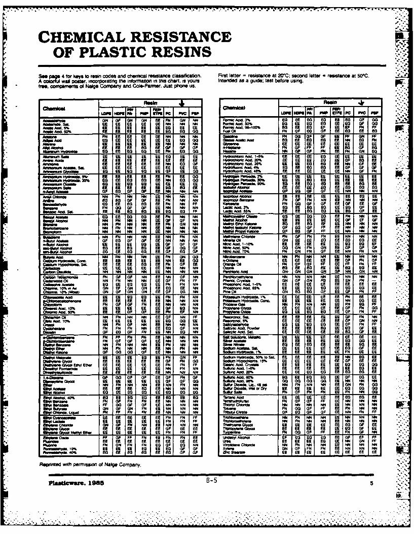
CHEMICAL RESISTANCE pOF PLASTIC RESINS
Seep e 4 for keys to resin codes and chemical resistance classification. First letter = resistance at 200C; second letter = resistance at 50C.A colorful wal poster, incorporating the information in this chart. is yours Intended as a guide; test before using.free. W m ent of Nalge Company and Cole-Pamer. Just phone us.
ChemW ic almcs!IcIPv fe o I* P "a I P-..4
ai ,NON OF ON ON IEE FN ON NN FO NCACd 3% 60 EEU EO 60 EE ifG OF G0OA080md.ft S8L EE EE EE EE EE NN NN NN Fai wC Acid: 50% 60 EE if i i f P 0Dame. Acid. 5% E6 EE EE EE EE if EE EE Fao elDd. W0100% if EE E0 FF EE UF FM FFAa* AmC~a.W% UE EE EE EE EE if E0 00 Fuel ON FN OF Ef OF EE EG EE EO
FN EE E EE NM NN, NN Own" FM 00 OF OF EE FF ON FF= cdEQ EE EE EE EE E if 00 GOM Amc Aci if3 EE f 60 EE NM if FM
M , EE EE EE EE N N NfE EE Fo . EE-,f EE E EE i F* M A"I EE EE EE if EE OF OF OF n.NIowo FN OF FF FF EE 60 OF EO
EG EEn~mNyide6 E E0 EE FN EG 00 WMID1 NN OF OIF FM if FM ON if
* Malgujy Sag EE EU EU EU EE 60 EE EE i4du~n Ad. 1-6% EE EE EE 60 EU EE EE EUARmm Aaft EE EE EE EE EE FE EE EE id , 20% Ef EE EE W EU OF 60 if
EE EE Ef EE E E N E G OF 1Y*00low Acid. 35% if EE E E EE NN OF ifPdw~~lACOW S8. E E FE EU EE EE EE EENdolui Ael. 4% EQ EE 60 60 EE OF OF OF -
AwmmAn O--- " EE if if EE OF EU = ad. 0% if EE EE E6 EE NM OF FMAW&mj M.UT % EE EE if if EE FN EE 00 "%*a" P.0ds 3% EE EE EE if EE EU EE EE
* AumAfiny40md 30% 60 EE Eaf e E E NM EG 00 Myddgom Fudd 30% if EE if CO EE EE EE EEif EE US e E E EE EE EENyam Peida Sim EQ EE EG 05 EE EE if EE
Sof EE EE EE EE EE ES EG EE EE 66 EE 60 EE if if 60Ommo OF E OF OF EE NM NM NM 1b,110 Amos OP E OF OF EE NN NN NN
AC~.NN FM NM NN EU NN NWN ,nP" AWWlo E E EE 66Ei EU EE*G AM 6 OF OF EU FM NM NM BVpt IU8.M61 FN OF FN NM EU NM NM NM
if EE if ifG EE FM NM FF KmmoFN 000OF OF EEfOF iE OF-. mm.FM 00 OF OF EU NN NM NM La Ad3% Eo EE if CO 66 if OF ifE
5m4W CKa. SOL EU EU if if EU 60 if FF LSM Aeld. 65% EE EE ifG 60 EU if OF EESuyIAo Ma0 ifEE E EQ EE if F NM NM mwud1lowe* EQ EU JEO EQ EE FM NM NM
Sm~AwilNM FM NM NM EE OF OF NN tK1AwiVOl iD EE EE fE EU EE OF EF OFNN FM NM NM EE FM ON NM Mw"-E-K.AIW EQ E fF EE NM NM NM
*aoqmNM FN NM NN, EE NM NM NM Mu" igabuty KOW. OF if OF FF EE NM NM NMNM NM NM NM EE NM NM NM MWM m P. IKoo- OF EQ OF FF EU NM N NM
@*ftgn. NM FM NN NM EE NN FMVW NM Msi1m.hlds FM OF IFM FM EE NN MMN NN04k" Aase2s OF EG OF OF 66 NM NN NM AM s UOil ON EE EE EQ 66 if if iE
=g~A=lo EU EUE iE if EU OF OF OF NliftA1d. 1-10% EIf EE EE 66 EU if ifG UPEAm0 E EE OF 00 OF NW* Aad 50% 00 ON FM ON EE OF OF OF
0114k" At" if EE if 60 EE OF I 0 OF NklcAcid:70% FM ON FM OF EE NN FM N@miydcAftd NN FM NM NM EU FM O GM 0Mddm NM FM N NM EU NM NM NMce""u Kfocxd.. coam EE EE if EE EE NM EE 00 n=o i E EE EE EE i OF FN OF
Ca~pdb.SN EE EE EE EG 66EF OF E6 Oill FM OF OF FF Ef FF FM FFE EE EE EE EU NM NM NM 00=ul EQ if if EE EEi 6066 E
Curti MUM*ld NM NM NM NM EU NM NM NM Ferdiii Acid ON- ON ON ON OF NM ON NM
61 N OF N NNEE NN NN N
C TMMOeo FM OF OIF NM E NM F PcIO MN N NN ENN MM MM NM. o ONN FM MM M OF FM PF 3. OF ON FO 66 EN FN
CONOW"v ACmmaf if EE 60 60 EU FM FM NMN ~ mloueAd 1-5% EUl EE 66 EE EE EU EU EU- ~ WlakON EF ON ON EU 60 EE NM P140OM id, 5% EU1 EU EQ if EU 5G if EU
11ri.1(0Z uI ON OF ON ON FE OF 60 NM P911.0 ON 60 if OF FE OF FM FFA cid EE EE EG if EU FM FM NM POM Mde. 1% EE F EE EE EU FM EU E
EEu EU E EU EE EU NM NM NN PWMa IVdd. Conrn EE EE EE E NM i EEFM OF OF FM EU MM NM MN P apGm NM FM MM NM EE FM EG FF
Chw .ad 10% EU EE EE EU EU OF if NM , .. Ef Ef EE EE EU OF FM 00C"u"ftI AM:50% E Of OF OF EEf F N E NM U onwl.AIddo EQ EE EG EG EE OF IFM FF
* Qemog ON N M FN N NM FE OF NN FF RAhbod~ SOL EU EU EU EU EU OF FM NMC' C E Ad. 10% EE EE E EE F I 00 EE ugNOC, 5% EE EE EE E EE OF ON NM
EEb NM FM OF NM EEMN MN MM sakyuld. iN if F EQ EEE OF N FFCjbawFM FM FM NM EU if OF MM SdCWICf MOd. Powdev 66 EE EE 60 if if OF EU
On EO f OF FM EE NM f NM Safy id ES, EE EE EU 66 EE E E OF EE
" o wb mmFM FP FM FN EE NM NM MM so 9 m M6C EE EE EE EU EE fE-F OF OF OF E NN NN, NMW tsrw EU EE EE E0 EU-.,
NN FM NM NM if FM NM NM Mis EQ EU if FE EE EE - EUl m NM FM NM NM EE NM FM NM Sodwn AMM.. Sat. EE EE E U f ifE OF EE
*0A1 u.OF 00 00 OF EU NM NM NM Sadkern ydrocle.1% EU FE EE EU EE FM EE EEofet" Ia MAE 66 E G EE FN O FF Sodum Hydrowid. 50% to SOL. EU EU EU EU EU NM CG EU
*kwt Ob WWui Olm iFEE FE EU iE OF FM 00 Sodun, Nypofloroe. 15% EE EU EU E OF 66 EE01"e6910 G"ud ElWl Ethe EU EE EU :E EU FM FM FP SaMM Ad. Cryot EE EU EU EU EE if if GODOimiiiyr Famminh EU EU EU EU EU MN FM NM SUllur ad. 1-6% EE EU EU EU E6 EU if EEMWOhuttao. EE EE EU E6 EE NN NN NM 31JAN1 Acd. 20% EU EU if 60 EU if if EU
1 .40br,.e OF 00 OF OF EE OF FM OF Suftft Add. 60% EQ EU if 60 EU OF EQ EEEEym~.lw EE i EE EE EU OF OF 00 SuktAid. 96% 00O 00 GO 00 EU NM NM NMhN" ~N P NM NM Ef NM FM4 NM Sa, 0lo0d". Laq. 46 pa NM FM MN NM EE ON FM 00
Ilm.EU EU EE if EU NM MM NM Su~x kds. Wetor ry EE EU EE EU EE C-0 if 00IIDmoif E ea EE EU to if i SLOW Samt FM OF FM FM EE FM NMN 0
EiiaNM4%U EU 60 60 EU if EU if Totfuiead EE EU EU 66 EU if if IfSeyiamn FM OF FM FM EU NM MM NM Teltahydmawu FM OF OF PP E6 NM NM NM
F~ .m.F 00 OF OF EU NMN M NN NNy Cliiaride MN NM MN NM EU NM NM NM591 uw.ON OF ON FM EU NM NM NMNhlil FM 00 OF FP EU FM NM NM5y Lbaiuid FM PP FM FM EUE NM NM NN ThMUly Cime OF if OF OF EU NM FM FP
0* UnyCyuWUnMo EE EU EU EU EU FM FM FF 1riilat~ww MM FM MM NM EU NM NM NMw* SU~Laau EE EU EU EU EU FM FM FF Thaiftme1s N FM NM NM E NM NM NM
vow 14.ch~mid ON OF FM NM EU NM NM NM Tevri.Oyw i" EE EU EE E U EE fC OF EE*wwyo i" E U EE fE EU EU OF EE EU ThprpysnyO l EUEU i EUEUi OF E
ef N -1yIMIyUI if" i- E E U EE EE E FM FM PFFuwnn FM 00 OF PP EU FM OF NM
po bW,. oxids PF OF FF FM EU FM FM EE Undecyl At"ho UP EQ EQ 60 EU OF EF FFEN EU E E E EU EE EE EU ike. EU EU EU if EU MM ON FF
P9g.FM ON FM FM 60 OF if NM vwnyddac Mns~l NM FM NM NM EU NM NM NM1mmlid.0% EU EU EU EQ EE to OF OF (rseON OF FM FM EU MM MM MM
Fomalo.4%Ea EE EG 60 EU 60 OF OF =3*..wa EE EU EU EE EU EE EU EU
* ~ReprWtd with PerMIssion of Nalge Company.
plasucware. 1985B55
THE USE & CAREOF PLASTICWARE*
-*
General cleaning tive cleaning agent: dissolve 120 items should be nnsed thoroughly with both biohazardous and radio-grams of sodium dichromate with distilled water before active matenal must first be
For mot general apfilctions, (Na2iCrO, - 2H20) in t000ml tap autoclaving. sterilized. Methods for removingplastics may be washed in a mild water. Carefully add 1600ml con- Polysulfone is autoclavable. radioactive matenal depend ondetergent, followed by a nnse with centrated suffunc acid to this Somewhat weakened by auto- the isotope used, its quantity, halt-tap water and then distilled water. solution. Nots: because this solu- claving, although less than poly- life. matenal and solubility. ForMost plastms, particularly LOPE, tlion generates considerable heat, carbonate. It autoclaved repeat- routine decontamination of plasticHDPE. PP. PMP and PA. have we recommend external cooling. edly, it will eventually fail under labware, first soak in decontami- "' "non-wetting surfaces which resist Do not mix in a plastic container, high-stress applicatins, such as nant/cleaner for 24 hours at roomattack ae are e nea D This solution is designed to high-speed centnfugation. temperature. Follow with severalnotuebri eneror Tsouis tnnsings in distilled water. To accel-scouring peds on any platic produce an excess of dlichromate Polystyrene, polyvinyl chloride, erate decontamination, increase
ela ar. Do not use atrong in the form of a precipitate which styrene acrylonitrile, acrylic, the cleaner concentration and so-alrline clenig agents with actually extends the useful life o low-density polyethylene, and lution temperature. Agitation andpotycarbonsta, chromic acid and dissolves as high-density polyethylene are scrubtxng will also speed thisDishwashers. Labiware washing needed. This chromic acid solu- not autoclavable under any condi- process. Note: do not scrubmachines can be used with all tion can be used repeatedly until tions. These plastics will melt polycarbonat. Always dispose
it begins to develop a greenish when autoclaved. of radioactive wastes and effluentsresins except low-tensty poly- color. indicating a loss of potency. Always loosen or remove properey. Je nethylene, acryli and pyStne Because of the excess dichromate closures before autociavng. ff For additional Information ondue to temperature limitations, built into this formula, this solution this is not done, pressure differ-The exceptional Strength ot ply- lasts considerably longer than entials will cauee onaer to elabwar,carbonate will be weakened by conmerally available solutions. collapse dung a cat ou Biosefety/Radiationrepeated washings in dish- Sodium hypochlonte solutions Gas sterliin.Safety offie, or refer to NIH pub-washers. Polycarbonate lahomre (blea chulications Biohazardous Safetyexposed to high stresses (can- are also effective in re- mentioned here may be gas ster- Guide, Laboratory Safetytnfxgo tor vacuum). (n moving organic matter. Use at ilized (ethylene oxide, formal- Monograph, and Radiationalways be washed by hand using room temperature for this dehyde). We recommend allowing Safety Guide.mild, non-alkaline detergents. To application, an appropnate aeration time suit-avd excessive abrasion of plas- ed to the particular application Trace metalstics in dishwashers, metal spindles terilizing plastics before using the item. Gas ster-should be covered with soft mate- Autoclaving. All items should be lization can cause pressure For most trace metal analyses,nal such as plastic tubing. The carefully cleaned before auto- differentials at elevated tem- plastic is generally -cleaner' orlabware should be weighted down claving. This will prevent baking peratures. so closure threads less contaminated than glass orand held in place with accessory contaminants onto the surface of should be totally disengaged. other matenals. However, plasticracks. the plastic. After cleaning, all Cm l s.ntaTiniie potei
Ultrasonic cleaners may be used items should be nnsed thoroughly Chemical sterilization. In gener- tan metals. To minimize potential
so long as the labware does not in distilled water before autoclav- al. all of the plastics mentioned low-level contamination, thesecan be sublected to commonly metals can be removed or leachedrest directly on the bottom of the ing. Certain chemicals which have used disinfectants (quatemnary from plastic by soaking in IN HCI
tank; use a cleaning basket. no appreciable effects on plastics u compnds luta- and nnsi in sie we Forat room temperature may causerinsing in distilled water. ForSpecial problemas deteroron at autoclaving tem- phors. formalin, benzalkonium more precise work, use HCI, fol-peratures and therefore must be chloride, etc.). There may be lowed by soaking in IN HNO3, and
Grease and oils. For many ap- removed, some surface attack (crazing) rinsing in distilled water. Soaking ,.,,
plications, washing with a mild when using a more chemically ag- time may vary according to indi-detergent will remove as Becuse of differences in heat gressive disinfectant on the less- vidual needs, but plastic should be
grease and transfer charactenstcs between resistant plastics (styrene. styrene soaked no longer than 8 hours.oils. plastics and inorganic matenals, acrylonitnle, PVC, polycarbonate, Caution: concentrated nitric acidOrganic solvents (such as the contents of plastic containers acrylic) with prolonged use. is a strong oxidizing agent and willacetone, alcohols or methylene may take longer to reach steriliza- Iodophor stains can be reduced embrittle many plastics. " "chlonde) may be used with cau- tlion temperatures (typically with sodium thiosulfate.tion when more rigorous cleaning 1210C). Therefore, longer autoclav- Dry het. Only Teflon FEP, poly-is needed. Extended exposure to Ing cycles may be necessary for met hyenTen polythese solvents may cause some liquids in large-volume plastic con- mathylpentene and polysultoneswelling of polyolefins. Be sure to tainers. Adequate cycles can be All other plascs above may showrinse off all solvents before using determined only by expenencelabware. Use only alcohols on with specific liquids and signs of accelerated oxidativepolycarbonate, polysulfone, poly- containers. degradation. If polysulfone orstyreno or PVC; other organic polymethylpentene containers aresolvents will attack these plastics. Polypropylene, polymethylpn- hot-air sterilized, be sure to re-Do not use any organic solvent tene, polyallomer, polysulfone, move polypropylene closures.Tetzeil ETFE, and Teflon ® FEPwith acrylic. may be autoclaved repeatedly at HazardOuS matter -
Boiling labware in dilute sodium 1210C, at 15 psi Cycles should bebicarbonate (NaHCO 3) is also an at least 15 minutes at 1210C to as- Before labware contaminatedeffective method for removing sure stenlity, with infectious or toxic materials isgrease and oil. Do not use with removed from the work area. itpo~yert~nae, ow-ensy pty- Polycarbonate is autocavable.polycarbonate. low-density poly- However, cycles should be hmited should be sterilized appropriately.ethylene, acrylic or polystyrene. to 20 minutes at 121°C. Poly- Autoclaving is the preferred meth-Organic matter. Chromic acid carbonate shows some loss of od for sterilization: however, anysolution will remove organic mechanical strength after repeat- method of chemical or heat ster-matter, but since this solution is a ed autoclaving and therefore may ilization compatible with the plasticstrong oxidizing agent, it will even- not function well under high-stress may be used Liquid waste con-tually embinttle plastics. To applications (such as centnfuga- laming biohazardous matenalsminimize embntttlement. soak lion or vacuum) Avoid using must always be decontaminated "ROWnOe wi PernIs.on of te Nne"plastic for no more than 4 hours. strong alkaline detergents on before disposal. teflon, ll'to-Rg TM E.I du Pont do
The following formula is an effec- polycarbonate All polycarbonate Labware that is contaminated Neoours & Company
6 B-6
-. :., :. .. :.-:-..--.------------------"-----. .. - .:. . :.-..1 : :- ::,-. : .....
r,' v%;
Dwe nsrmntIc
Hihay22 t1
B-7~

CLV
CL. ~
UU 3 i. 3
0-1 42U. ~ '*
(1' * IlbL hzU*.S
xU r . ~ t L c -', R
coU~ C ~4lU * f~*.l.
C, oz
!k C6 g
a tatt
W Ca
B-86

7w - E IL It
ZL- ta!- o --=2* 7 -
72- L-2
I1 Z - -'tFE -3 -
z
7' Z 7 ~ -2q 4.
Cc~ c.i
2P-"S- -.. Mc .9- C
72 C -3 E- 1- 6 S ~ S
--- CC , , -
p~ 3N51S~
*L E~ojtF *~jo4 A ~-,79tn Z QE '&Q 13 z
2 W I32u~
;j CAz r
-...- ~ ~ -: S.
'-~~~~~ ~~ --"v-j2a 0 9 ~,uZ~
-;.,A us EB-91
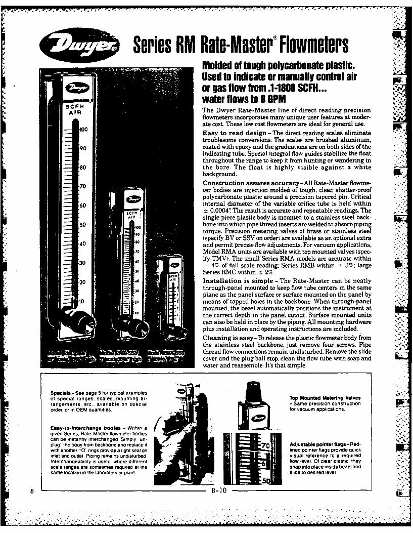
Series RM Rate-Master® FlowmetersMolded of tough polycarbonate plastic.Used to indicate or manually control airor gas flow from ,1-1800 SCFH...
SC-H water flows to 8 GPMAIR The Dwyer Rate-Master line of direct reading precision
flowmeters incorporates many unique user features at moder-
ate cost. These low cost flowmeters are ideal for general use.
Easy to read design -The direct reading scales eliminatetroublesome conversions. The scales are brushed aluminum,
90 coated with epoxy and the graduations are on both sides of theindicating tube. Special integral flow guides stabilize the floatthroughout the range to keep it from hunting or wandering in
80 the bore. The float is highly visible against a whitebackground.
70 Construction assures accuracy-All Rate-Master flowme-ter bodies are injection molded of tough, clear, shatter-proofpolycarbonate plastic around a precision tapered pin. Critical
60 internal diameter of the variable orifice tube is held within_-t 0.0004'" The result is accurate and repeatable readings. The
single piece plastic body is mounted to a stainless steel back-50 bone into which pipe thread inserts are welded to absorb piping
torque. Precision metering valves of brass or stainless steel(specify BV or SSV on order) are available as an optional extraand permit precise flow adjustments. For vacuum applications,
70 Model RMA units are available with top mounted valves (spec-ifv TMV). The small Series RMA models are accurate withina 4% of full scale reading; Series RMB within = 3%; large WK
s Series RMC within _t 2%.2E All Installation is simple- The Rate-Master can be neatly
through-panel mounted to keep flow tube centers in the sameplane as the panel surface or surface mounted on the panel by
10 means of tapped holes in the backbone. When through-panelmounted, the bezel automatically positions the instrument atthe correct depth in the panel cutout. Surface mounted unitscan also be held in place by the piping. All mounting hardwareplus installation and operating instructions are included.
Cleaning is easy-Th release the plastic flowmeter body fromthe stainless steel backbone, just remove four screws. Pipe ,'-
thread flow connections remain undisturbed. Remove the slide* cover and the plug ball stop, clean the flow tube with soap and
water and reassemble. It's that simple.
Specials - See page 5 for typical examples 3of special ranges, scales. mounting ar- Top Mounted Metering Valvesrangements. etc., available on special -Same precision constructionorder, or in OEM quantities for vacuum applications.
Easy-to-interchange bodies - Within agiven Series. Rate-Master flowmeter bodiescan be instantly interchanged Simply un- I,"plug the body from backbone and replace it i 7 E Adjustable pointer flags-Red-with another. 0 rings Provide a tight seal on lined pointer flags provide quickinlet and outlet. Piping remains undisturbed visual reference to a requiredInterchangeability is useful where different flow level. Of clear plastic, theyscale ranges are sometimes required at the snap into place inside bezel andsame location in the laboratory or plant slide to desired level
8 B-10
. .-. C .7 .

SPECIFICATIONSM40 Body. Bezel Polycarbonatead Tube*___________
W~te Metal Pans Stainless Steel (except for optional brass valves)*Floats St. Steel. Six. Glass. Alum., K Monet
Float Stops Polycarbonate
PieCnncin Model RMA. 14" Model MS. /.:...Rings Neoprene adBuns N SCPM
FfdpStainless Ste" brazed to Stainless Steel AF~tt~ngsbackbone plate
Rivet Stainless Steel, set into slots too0
ScleBrushed Aluminum -Clear Epoxy Coated 90Kniols ASS PlasticPressure Rating AMA 100 PS.I.. AMS 70 PS.. AUC 35 PS.I. max. 80Temperature Rating To 1 30' F maximum
AccuracyModel AMA. 4%; Model RMS. 3%: 7
_______________Model RMC, 2% of full scale _____
___________OPTION4S AND ACCESSORIES CODEBrass B
Moto______Valve Stainless Stee S0
Tog Mounted Valve Stainless Steel -available only on MV40AMA for sir (vacuum applications)______Pointer Flag Polycarbonate PF30
20
_ _ _ _ _ _ _ _ _ _ _to
Series RM RATE-MASTERO Models and RangesModel AMA -r Seale, Model RMS-5s"cale Model RMC-lr Scale
Range Order- Range Order- Rangea Order- *-
*SCFI4 Air ing No. SCFH Alr ing No. SCFII Alt ing No.*05-'5 1 .5-5 49 5-50 101
.1-1 1-1 50 1-100 102
2-2 3 2-20 51 20-200 1035-5 4 5-50 52 40-400 104
1-10 5 10-100 53 60-600 105 DIMENSIONS-iN INCHES _____
2-20 6 20200 4 10-100 106Model RUA Model Rils Model RMC*~~~~~, 2-0 6 020 4 10-00 0
*5-50 7 40-400 55 120-1200 107 A4~ 1i10-00 5-50 56 18-180 183 61/4s 121A.
10-100_ 8 050 5 8-80 18/ NPT Conn. 1/. NPT Conn. 1/ NPT Conn.*15-150 9 60-600 57 SCFM Air 3le8
*20-200 10 Gal. Water 1-10 121 C 10-32 Thds. 14-20 Thds. %-24 Thds.CAiti.potrhour 2-20 122 D
55 15 1-2 8 330 13E Il, 17/ 2/
5-100 150' 1-20 83 Gal. Water F IV,$ 12/ 2'!A30-240) 11 4-40 84 per hour G 1I',
* 5-500 12 10-100 85 1-20 134 H 1'.1
*100-1000 13 8I9 135 11'AS 21A
200-2500 14 GlWof(OPEN) (8V or SSV MOOELS ONLY)
LPM Air per__ min 11. 25-5 2611 11K 413 J 83/ 1 53A
1-10 21 222 12L1V22/
2-25 22 3-3.6______ 143________
5-50 236- 14
5-70 24 How Orde10-100 25 H w ToOre
CC Wataer/min. 321. Select model desired by letter designation. RMA,5-50 32RMB. or RMC.
10-110 33_______ 2. Specify range desired by adding the order number20-300 Water/hr.____ after a dash following the letter designation. Ex-
Gal. Waer2r ample RMA-6.I-lI 12 _________ ___________3. If additional features are required, and available.2-24 add the option designation to the basic model code
4-34 4 -e.g.. B V for Brass Valve, SSV for Stainless Steel5Accrac 48 Valve, and TMV for Thp Mounted Valve. For exam-8% ple, RMA-6-SSV is the 2" scale flowmeter range
No. 6 with a stainless steel valve.4. Add accessories as desired.
B-1i
9 I
X-I

CON VERSION CURVES FOR GASESGAS~~j~ PRSUEPI LWATOPE-2_nf
10
00
02
6 20
I A1v''1
-5
0 I 2 3 £ S 6 1 90 1 2 1 3A 15 1 17 a 9 20CC A T A GAS FLOW CORRECTED FOR P REiF URE'YSD 0
* ~ ~ PIFI oR V OnFenent appFERoaED corcto AacRor may719. be -1312- 1ee0rnr wher A ~ Obere f mte redn gAvt* U~ng 0O~in orm 1s
9.rsms 4 Ox/ pcfcgaiyo i
V.G V// SpcRi grvtyo asbig sd nfowewhr6,=Osre lw ee edigoiial airtdfrar
Inlet pressureon TMV models.erel l ,-ow ere flows f h lg ter a nvrhlsg heecat nIf mor convnientapproimatecorrection factors can be qeemne c uite sf ul whreceno d ecin g rithym l hagsi
4~~~~~~~~~~~ =. S~~lIUkF0 ,X TB 2 pesr'ad Specific gravity o iA. Pieamo:e at dica- on ai u M nt.Ilt ru nTvmdl
................................ *being**used in. l w.e..

17* 7- -T7 . - -JJSFlowmelers and Sight Flow Indicators
How flowmeters work:Variable area flowmeters are basically vertical internally- tion to laminar flow are low velocity (often associated with atapered tubes mounted with the large end at the top. A float lightweight float), low density or specific gravity and highor rotor with an outer diameter slightly less than the mini- viscosity of the flowing fluid. When laminar flow conditionsmum diameter of the tube is placed inside the tube. The prevail, a greatly expanded scale is usually required. Metersclearance space between the float and the tube forms an operating in the laminar flow area are very difficult to man-annular passage or orifice. As the tube is tapered, the area of ufacture and calibrate to the degree of accuracy usuallythis orifice is larger when the float is near the top than it is expected of variable area flowneters.when the float is near the bottom. By connecting the tube Turbulent flow - Most variable area flowmeters operate ininto a fluid flow line so flow direction is from bottom to top, the turbulent flow range which occurs below sonic velocitiesthe float will move upward and be supported at a point and above the laminar flow range. In turbulent flow, thewhere the orifice is just large enough to pass the fluid flow- flowing fluid particles move in random paths within theing through the system. stream - rather than in violent shock waves as in sonic flow
or very smooth parallel paths as in laminar flow. In tur-bulent flow, variables follow the relationships shown in thecurves on Page 4. These curves are quite accurate for small
TUB NARTUB NARchanges in pressure and specific gravity. For large changesSWLYWTPEor where a change in viscosity is involved, it is much better
to have the flowmeter recalibrated for the specific conditionsunder which it will be used.Reynolds Numbers - Reynolds Numbers are useful in
iE FLOW GUIDES IN RATEMthe study of fluid behavior and are quite helpful in separat-ing laminar and turbulent flow. The Reynolds Number of afluid flow system is described as a dimensionless index. It is
Several Forces are involved - The precise position of the equivalent to the diameter of the orifice in feet times thefloa ithinrthes te isdoemedTh preise l forsicting average velocity of the fluid in feet per second times thefloat within the tube is determined by several forces acting density of the fluid in pounds per cubic foot divided by theon it. These forces are: 1. The weighit of the float; 2. The absolute viscosity in pounds per second foot. A system oper-velocity pressure of the flowing fluid multiplied by the area ating with a Reynolds Number of less than 2000 is said to beof the float; 3. Buoyancy of the float (weight of fluid volume subject to laminar flow. whereas Reynolds Numbers abovedisplaced by the float; 4. Viscous aerodynamic or hydro- 3000 are clearly in the turbulent flow area.dynamic drag of the fluid on the float. The float's weight actsdownward - while velocity pressure. buoyancy and drag allact upward on it:. How sight flow indicators work:Read-out and scales - By making the tube transparentso that float position can be seen and by providing a scale A sight flow indicator basically consists of a small housing ." -
along side, we may "read" the float position in terms of equipped with a glass window which is inserted in a run of . -numbers on the scale. These scale numbers can be of two pipe to observe the flow of the fluid in the pipe. To enhancetypes: 1. Of an arbitrary nature (by themselves they mean the visibility of the flow, a spinner is often incorporated innothing, but become meaningful when compared with a cal- the indicator. The axis of the spinner is offset from the centeribration curve) or: 2. They can be precalibrated for direct of the flow stream so that fluid impinging on the spinnerreading to show the actual volume flow (in cfm, cc per min- vanes causes it to turn. The spinner also aids in the detec-ute. etc.) of the fluid for which the flowmeter is calibrated. tion of low flows as well as providing visibility of flow from aLimiting factors - Although the basic relationship out- distance. In addition, the speed of rotation gives a relativelined above is linear, certain fluid properties tend to modify indication of flow velocity Midwest Sight Flow Indicatorsthis relationship. These changes are accentuated where the are also available with hinged flappers instead of spinnersvariable orifice formed between float and tube becomes to indicate bi-directional flow.either very large or very small. For example... Sight flow indicators can be provided with a single windowSonic velocity - Where the orifice is particularly large on the front of the indicator or double windows, one on the
and is combined with a heavy float, velocities of a gas or front and one on the back of the indicator. Double window lqiother fluid through the orifice area can approach sonic ve- units are best when observing the clarity or color of a liquid.locity. In this velocity range. reflected shock waves cause the Midwest single window units are always equipped withfloat to become unstable, and it will typically hunt from side spinners to provide for observation of clear fluid flows at theto side and from top to bottom within the bore. At best, this lowest cost.condition makes it impossible to take a reading. and at worst Vertical tube-type sight flow indicators consist of a clearmay even destroy the flowmeter. The addition of flow guides glass tube, equal to or greater than the diameter of the pipe(built into certain Dwyer Rate-MasterI flowmeters can into which it is inserted, and are utilized to observe high flowoften improve the stability and performance of the system rates in vertical pipe runs. No spinners or other type ofby channeling the flow into multiple streams that equalize detection devices are incorporated in these units. As a re-dynamic effects and preventing oscillation of the float. This suit, they offer no significant resistance to flow and thereforehas the net effect of moving the limit of satisfactory opera- provide the lowest pressure drop of any type sight flowtion upward. and thereby expanding the range and accuracy indicator.we can achieve with any given flownieter tube. " Midwest Sight Flow Indicators are available with specialLaminar flow - In flowmeters where the orifice area is materials to meet various applications. Optional materialsextremely small, the conditions result in smooth flow. or are available for the sealing gaskets, spinners, and housingslaminar flow. Other factors which contribute to the transi- or flanges.
2 Copyright 1944 owve, Instruments wc B -1 3
. ._ .. . ......... .. . . . - . . . . .. ... ..- ., .. ,,. ,....- . . . .... 2. . .,.., . ..,::. ::.. :::.-.: .,...: . : .-.. . : : . ..-..- . -: : .. . . , : : . . -,- . .. . . . .. . . . -. .., . ,- . , , . -

NONE
Fraunhoter-Instilut ITA Insatutsted Grtahaft 0-5948 Scsrmauk brg Fr3.ufhofU4rdh boJt
Dr. William D. Farthing f[r Toxkalgi oundPhysics Division AeWfb u,,Institutstel Grafschaft
Southern Research Institute sttteracat ii,
P.O. Box 3207/A institutsleitung:Dr. Hubert O1diges .-Prof. Dr. Wemer Stober
Birmingham, Alabama 35255 N. N.
U.S.A. GafscdVHodLcsueand//- " -"19 ' / o "F '5948 Sdirnalenbeig i';L9 7 Telefor,029721494-,96
Ihr Zeichen: Ihre Nachnctt: Unser Zecmen: Beaboedter:
Ho/hei Ourchtw: r. j
Benfit: simpactr, 20. Jan. 1983Virtual impactor
Dear Dr. Farthing,
thank you very much for your telephone call on 18 January 19d3.
We offer you a virtual impactor according to figure 1 of the article
by Masuda, Hochrainer and Stdber in the Journal of Aerosol Science10 (1979), 275-287. The material of the impactor shall be brass.
The price is DM 6804,- and includes material, manufacturing and
shipment by air mail. The delivery time will be 3 month after receipt
of -your order.
With kind regards,
(Dr. K. Schoene) (Dr. D. Hochrainer)
Enclosure: Reprint from J. Aerosol Science
Banwrumdun.: PosscWeck Munchen Fraonnoter- Ge scmtan VorStand:OSfIsche SaIC. Munclen Konto.Nr 2525-809 zur Fd erung Or or nt, Hanz Keller. PrisidentKonto Nr 75-21933 8LZ 700 100 80 dot af.qowendten Or jur Ebemard SchloephorstBLZ 700 700O 1 B-14 Foschung. v Of r,, OWe u-Ulne .W ee
. .. . . .. . ..• .° . . "° .° " .. .% ° . " . % % % ° , " , " , % " % " . °%
°
' , •'. .
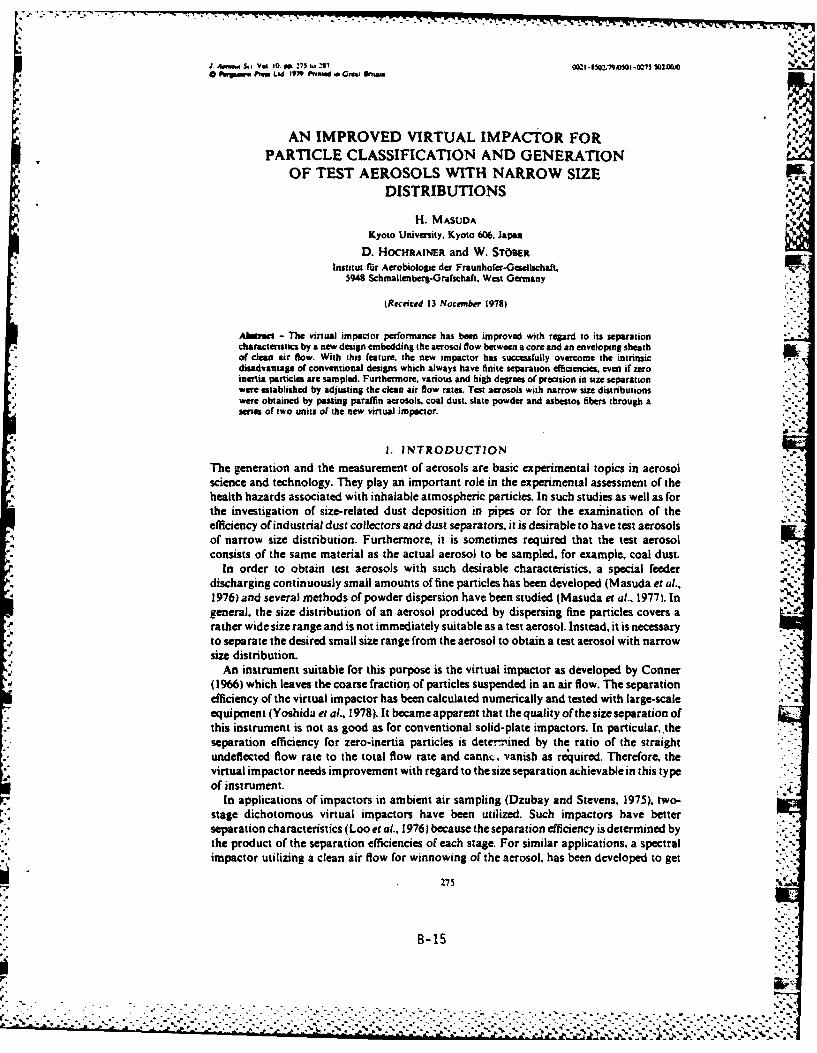
:. '
J A..d S,, Vol 10. PP 275 to, 297 002 - 650,lsoMI -0275 102t0M00 wpumu Psum Lid 1979 Pvnau a 0MwI gnu".
.N.
AN IMPROVED VIRTUAL IMPACTOR FORPARTICLE CLASSIFICATION AND GENERATION
OF TEST AEROSOLS WITH NARROW SIZEDISTRIBUTIONS
H. MASUDA
Kyoto University, Kyoto 606. Japan
D. HOCHRAINER and W. ST60ERInstitut fir Aerobiologie der Fraunhofer-Geselischaft,
5948 Schmallenberg.Grafschaft. West Germany
(Received 13 November 19781
Abused - The virtual impactor performance has been improved with regard to its separationcharacteristics by a new design embedding the aerosol flow between a core and an enveloping sheathof clean air flow. With this feature, the new impactor has successfully overcome the intrinsicdisadvantage of conventional designs which always have finite separation efficiencies, even if zeroinertia particles are sampled. Furthermore. various and high degrees of precision in size separationwere established by adjusting the clean air flow rates. Test aerosols with narrow size distributionswere obtained by passing paraffin aerosols, coal dust. slate powder and asbestos fibers through aseries of two units of the new virtual impacor.
1. INTRODUCTION
The generation and the measurement of aerosols are basic experimental topics in aerosolscience and technology. They play an important role in the experimental assessment of thehealth hazards associated with inhalable atmospheric particles. In such studies as well as forthe investigation of size-related dust deposition in pipes or for the examination of theefficiency of industrial dust collectors and dust separators, it is desirable to have test aerosolsof narrow size distribution. Furthermore, it is sometimes required that the test aerosolconsists of the same material as the actual aerosol to be sampled. for example, coal dust.
In order to obtain test aerosols with such desirable characteristics, a special feeder -..
discharging continuously small amounts of fine particles has been developed (Masuda et al.,1976) and several methods of powder dispersion have been studied (Masuda et al., 1977). Ingeneral, the size distribution of an aerosol produced by dispersing fine particles covers arather wide size range and is not immediately suitable as a test aerosol. Instead, it is necessaryto separate the desired small size range from the aerosol to obtain a test aerosol with narrowsize distribution.
An instrument suitable for this purpose is the virtual impactor as developed by Conner(1966) which leaves the coarse fraction of particles suspended in an air flow. The separationefficiency of the virtual impactor has been calculated numerically and tested with large-scaleequipment (Yoshida et at., 1978). It became apparent that the quality of the size separation ofthis instrument is not as good as for conventional solid-plate impactors. In particular,.theseparation efficiency for zero-inertia particles is determ~ined by the ratio of the straightundeflected flow rate to the total flow rate and cannc. vanish as reqjuired. Therefore, thevirtual impactor needs improvement with regard to the size separation achievable in this typeof instrument.
In applications of impactors in ambient air sampling (Dzubay and Stevens, 1975), two-stage dichotomous virtual impactors have been utilized. Such impactors have betterseparation characteristics (Loo et al., 1976) because the separation efficiency is determined bythe product of the separation efficiencies of each stage. For similar applications, a spectralimpactor utilizing a clean air flow for winnowing of the aerosol, has been developed to get
B-15
.• . .
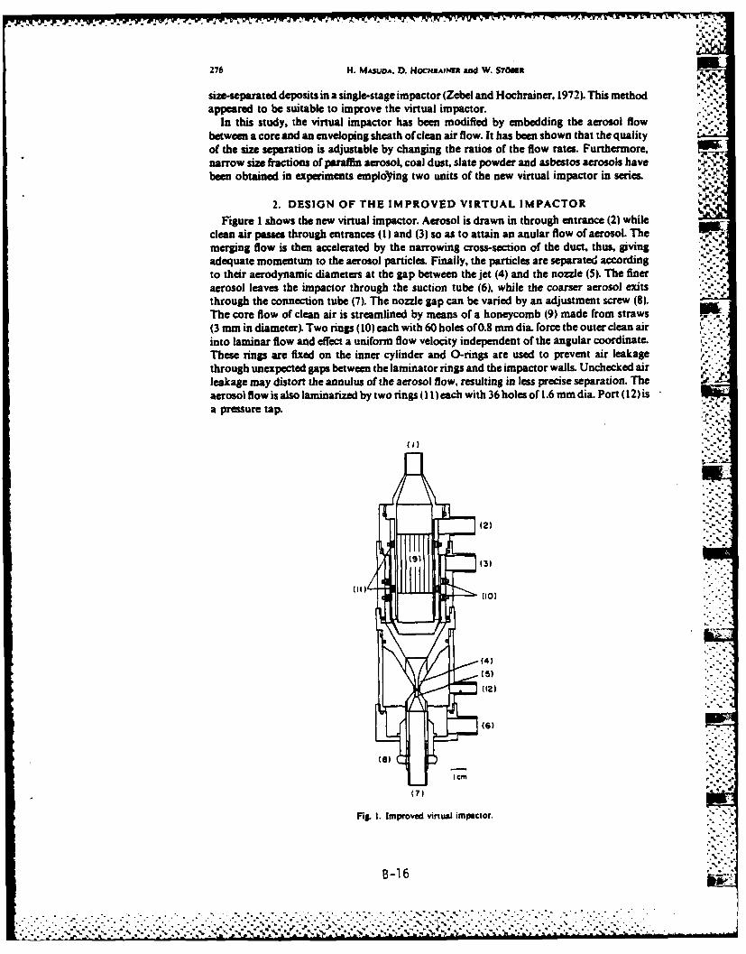
276 H. MASUDA. D. HOCHRAWI and W. STOMi A%
size-separated deposits in a single-stage impactor (Zebel and Hochrainer, 1972). This methodappeared to be suitable to improve the virtual impactor.
In this study, the virtual impactor has been modified by embedding the aerosol flowbetween a core and an enveloping sheath of clean air flow. It has been shown that the qualityof the size separation is adjustable by changing the ratios of the flow rates. Furthermore,narrow size fractions of paraffin aerosol, coal dust, slate powder and asbestos aerosols havebeen obtained in experiments employing two units of the new virtual impactor in series.
4.
2. DESIGN OF THE IMPROVED VIRTUAL IMPACTORFigure I shows the new virtual impactor. Aerosol is drawn in through entrance (2) while
clean air passes through entrances (1) and (3) so as to attain an anular flow of aerosol. Themerging flow is then accelerated by the narrowing cross-section of the duct, thus, giving ,-."adequate momentum to the aerosol particles. Finally, the particles are separated accordingto their aerodynamic diameters at the gap between the jet (4) and the nozzle (5). The finer ,..aerosol leaves the impactor through the suction tube (6), while the coarser aerosol exitsthrough the connection tube (7). The nozzle gap can be varied by an adjustment screw (8).The core flow of clean air is streamlined by means of a honeycomb (9) made from straws(3 mm in diameter). Two rings (10) each with 60 holes of 0.8 mm dia. force the outer clean airinto laminar flow and effect a uniform flow velocity independent of the angular coordinate.Them rings are fixed on the inner cylinder and 0-rings are used to prevent air leakagethrough unexpected gaps between the laminator rings and the impactor walls. Unchecked airleakage may distort the annulus of the aerosol flow, resulting in less precise separation. Theaerosol flow is also laminarized by two rings (11) each with 36 holes of 1.6 mm dia. Port (12) isa pressure tap.
m
' (2)
(I(3)
(10)
(4)
(5)
(6)
I CM
(7)[1 " .-',
Fil. I. Improved virtual impactor.
B-16
~%." . ". •" .. .' .- ,'.. ." " ..• . ." " "°-.°- " %". " % •.'," ." x %" % ," ... • " %...".................................... ,
Improved virtual impsar 277
Memoi
Fig. 2. Schematic graph of annular aerosol Raow in the je.
3. THEORETICAL ASPECTS OF THE SIZE SEPARATIONEFFICIENCY
When a monodisperse aerosol is sampled with the impactor, the accelerated particlewithin a concentric circle of critical radius R, are separated from the main flow and pass intothe straight undeflected flow through the nozzle (5). Then, the separation efficiency q isdefined by
f27runr dr
f2nunr dr0g
where n is the number concentration of aerosol particles, ui is the air velocity and R is the jetradius. The distribution of the particles in the annular aerosol flow is assumed to be uniform,iLe.
n(rl constant: R, S r < R,
0: R, .r :SR
As indicated in Fig. 2. R. and Rs, are the inner and the outer radius of the annular aerosol flowin the jet (4), respectively.
From equations (1) and (2h. it is clear that
1-0 for 0 sR, <R. (3) .
and
'7.1 for R1,< R, R. (4)
B-17

*~~1 1- - - h --
275 H. MASUDA, D. HOeMRAIN! and W. STOMa
If the critical radius R, is between R. and R, then the separation efficiency becomes:
r dr ur dr ur dr Urdr
ur dr r ur dr ur drfi
(5) r r
which can be rewritten with the flow rates as
QI QI A,
where Q, is the total flow rate, Q, is the aerosol sample flow rate and Q1 is the clean air core iflow rate in the center. The factors z and P in equation (6) are defined as flow rate ratios
z-QdQ, P-1/Q,(7)and
ur dr-o" (8) '"
is the separation efficiency of a conventional virtual impactor which does not have any cleanair flow. Q. is the flow rate within the critical trajectories. When the velocity distribution isuniform, equation (8) reads 2
17o \ (9)
This indicates that the separation efficiency P1 of the new virtual impactor can beconsidered as being composed of a separation efficiency qo of a conventional virtual impactorand the flow rate ratios z and P.
The slope of the separation characteristic may be expected to depend upon the flow rateratio a, while the value ofP determines the critical Stokes number (see equation (16)) I - owhere't = 0. '--
In order to obtain the critical Stokes number Oo, equation (6) will require
#=uno for 0,-0'0 (10)
or by definitions,Q" 1 = QO= (11)
which is satisfied by R.- R. Then, if Q3 is the undeflected flow rate through the nozzle (5),the condition for - 0 is necessarily
Q3 < Q. (12)
because no higher flow rate than Q, can pass through the nozzle if the flow shall not containaerosol particles.
For 0 < *0, equation (6) will turn negative and does not yield physically meaningful data.However, for o "= 0, the conventional virtual impactor has a finite efficiency
010 (13)
and it follows from equation (10) that
(14)
B-18
> ,, . ( . . . . . . . .

Improved virtual impactor 279
On Buffer,
Fig., 3. Scbeme of the ezpsrimmnil arraugeme.u,.L
V.-° •
4. EXPERIMENTAL ARRANGEMENTS AND PROCEDURES -The experimental arrangemnt for testing the performance of the new virtual impactor is ""'
shown in Fig. 3. The performance tests were carried out with latex aerosols (Dow Chemical ""Co.). The air flow rates were measured by rotameters which had been calibrated with a gas " 'meter. The two separate aerosols leaving the instrument were collected on the membrane ,_.filter F1 and F2 (Sartorious-.Membranfilter GmbH). After sampling, the filters were exposedto acetone vapor for about 2 hr in order to make the filter foil transparent. Subsequently, the :particles collected on the filters were counted under a microscope and the separation 'efficiency was calculated by.
N,
N + N2'(15)
where N, is the number of coarse particles collected on the filter F, and N2 is the number of .--fine particles collected on the filter F2 . At a total flow rate of 20 ./mmn the wall losses, which "-:may depend on flow rate, particle size and particle material (Loo et aL., 1976; McFarland et " "aL, 1978) were only 0.6 and 0.2%/ for 0.822 and 1.10 rn latex particles, respectively."'-'
In all the experiments, the ratio of the straight undetlected flow rate Q3 to the total flow rate :."Q, was held constant at 0.1. However, the total flow rate was varied between 5Sand 30 1./mi.The separation efficiencies obtained were expressed in terms of the square root of the Stokesnumber q , a dimensionless inertia parameter giving'.-
where D is the jet diameter 2R, D is the aerodynamic particle diameter, uo is the mean air .i
velocity, p is the air viscosity and p is the particle density. The Cunningham's slip correction .factor C is given (e.g. Fuchs, 1964) by
C -l1+ 2D {1.3 + 0.41 exp(- 0.4- e)}. (17).'..
where A is the mean free path length of the air molecules.Another set of experiments involved two of the new virtual impactors in series. This
B-19 :"
• . *.... ..... ".................................,.... .... . ' :shown in Fig. . ..fr .c.e.swr:a................ . .o (........

230 H. MASUDA, D. HocIHaAin and W. STOgen
arrangement aimed at the generation of quasi-monodisperse aerosols. Paraffin particles, coaldust (Trenonia, 11, fine; p, -1.32 g/cm3, measured by the pycnometer method), slatepowder (IKO-Schiefer; p, -2,78 g/cm 3, measured by the pycnometer method) andasbestos fibers (U.L.C.C. standard-Amosite) were used as test materials. The coal dust and theslate powder were brought into aqueous suspension by small amounts of soap and atomized .-
with compressed air However, the asbestos aerosol was generated from a fluidized bedby mechanical vibrations (Spurny et al., 1975). Other experimental conditions are listed in . ~Table I.
Table 1. Experimental conditions
Latex particles:D - 0.52,.0.727.0.822. 1.10. 2.02 IanP, - 1.0O g/cm,
Mean air velocity: uo- 30-150Orn/secStoke number: --0.03-1.5(-Flow Reynolds number in Re - 400-20000 N imspoctor jet:Jetdiameter: D -0.2cmGap between jet and lower 0.05 cmnozzle:
5. RESULTS AND DISCUSSIONFigure 4 shows the experimental results obtained with the new impactor when no clean air
was used. In the low inertia region (,/0, <0.4), the data are almost on the theoretical curvecalculated by assuming potential flow (Yoshida et aL., 1978). However, with increasinginertia, the experimental separation efficiency increases faster than predicted by the theory.This tendency is similar to that obtained by other investigators (Conner, 1966; Yoshida et aL.,1978). Such discrepancy between data and theory may be explained by the fact that theparticle trajectories will deviate from the streamlines in the curved section of the narrowing
0~
--- Ceitntugal effect 9/
Modified ve4OCi1y
050
1 00 r/P
0
0 1-02 0.5 1
Fig. 4. Separation characteristics of the new virtual impactor without clean air flows (small framegives the modified velocity distribuaonl
T'he generos assistane of the Steinkohlenbergbeuverern. E=Men in obtaining the sample: and the information0n the dessouu s gratefully acknowledged.
B- 20

Improved virtual impaor 281
duct for the merged flow, especially in the vicinity of the cylindrical section of thejet (4). Here,the radial flow components toward the center must decelerate so that the particle inertia willbring the trajectories closer to the center axis. In order to estimate the deviation, it may beassumed that the centrifugal force mpu/r o (m: particle mass, ro: radius of curvature of thecurved section of the jet) will act upon a particle within a range of one jet diameter above thecylindrical section of the jet. The solution of the equation of motion is represented by
where 6 is the deviation of the particle trajectory at the jet inlet. Fo - i/D and t = tuo/D. Foand 'are dimensionless radius of curvature and time, respectively. For the instrument underconsideration, values of Fo = 10 and = I may be used. The outer radius of the aerosol flowR' is then given by
-i- 1 - 25 (19)
and the separation efficiency must be modified to F&7
PI; -23) " (20)
The results of these calculations are shown in Fig. 4. The prediction is considerably improved,showing that the main cause of the discrepancy may be the deviation of the particletrajectories from the streamlines in the curved section of the jet (4).
In case of clean air flow, it can be shown that also a ratio RW/R. for the annual aerosol flowis given by equation (19). when the following substitutions are made for 0, " and F0 inequation (18):
D -Dt.% - t
FO. = (r = ( ) (21)
Therefore, a general relationship
R, R; R'R. , T 1 -25 (22)
can be obtained and it is easy to show that equation (6) is also valid when v0 is replaced by n6.Although a uniform distribution of the inlet velocity is a reasonable assumption in view of
the high acceleration, the effect of the distribution may also be .-.timated by assuming avelocity distribution:
u .32 - ( .)(r (23)
The small frame in Fig. 4 gives the modified velocity distribution. The separation efficiencycan be obtained by use of equation (8), (23) and the same critical radius Re as in the potentialflow calculations. The prediction is qualitatively improved as shown in Fig. 4, indicating thatthe actual velocity distribution may be another cause contributing to the discrepancybetween the data and the unmodified theory.
In spite of the theoretical bias, almost all the data are represented by a single experimentalcurve for qo. Therefore, it is possible to interpret the separation characteristics of the newimpactor with clean air flows based on the experimental curve for io. Figure 5 shows how theseparation characteristics change experimentally with the flow rate ratio a. The curves in thefigure are obtained by use of equation (6) and the experimental curve in Fig. 4. The predictionis satisfactory and the quality of the separation, i.e. the slope of the curves, is adjusted by the
B-21
-............................ ,.......- . . . . .,, ,,,. . . . . . . . . . . . . . . .. ....- --..-.-. :- - :- - "" : " "" " ". . .

232 H. MASUDA. D. HOCHRAiNER and W. STOBER
o2 * 3 a -4 -1o
.o06 0-1A 0-2.2 5.6.4
Exp.a" - Prediction
050
0 *
. I .-
1
05
'I
0.2 05 06 05 08 05 08 05
Fig. 5. Separation efficiencies of the new virtual impactor as a function of clean air flow rate ratio x.
flow rate ratio (x. With increasing flow rate ratio m, the slope of the separation characteristicbecomes steeper, an effect predicted by equation (6). When - 2, the quality of separation is %%.
almost the same or better than in case of a conventional solid-plate impactor. Therefore, a -
2 may be sufficient and suitable for actual industrial applications of the impactor as a powderseparator. Besides this fact, the new impactor can be used continuously to get large volumesof size-separated airborne products.
Figure 6 shows the results obtained for several values of at a = 5. Agreement betweendata and the predicted curves is satisfactory for f = 3 and 3.5. In the other cases, at least thecut-off size, as defined by the separation efficiency q = 0.5 coincides with the prediction,showing that the cut-off size is adjustable by selecting a proper flow rate ratio P. However, theexperimental data deviate from the prediction when the flow rate ratio Pt is small. Toelucidate the cause of these deviations, a cover glass was placed on top of the lower nozzle at adistance of I mm from the jet so that particles were collected by impaction. Subsequently, theshape of the particle deposits on the glass was inspected under a microscope. The results arepresented in Fig. 7. The shapes for f = 3 and 3.5 are not shown because they were almostperfect circles. The shape for P = 2.5 is still reasonably circular, but the shapes for P = 2 and . ..
1.5 are considerably distorted. With these data and the experimental curve in Fig. 4, thea-7-
a-5 00 ,'5 ' 2 0 2.5 035
- 1-00
Prediction
~ci . to
. L q 7 %°
05 '] O 07 03 05 07. 05 07 05 0 5 0
Fig. 6. Effect of flow ratio 0 on sepaation characteristics.
B-22
Predic".-n
[.. .-.,..'.'- -.-'.'., .,,. '.-.-...'.-.-.-.,..,< > ,.-',"....,.... .,'.,,,.,."S.., ::-, -t .,...,... - .1* -., .

Improved virtual impactor 283
t,.,
Fig. 7. Distortion of annular aerosol flow by different flow ratioas (at-5)
separation efficiencies were calculated by numerical integration assuming that the criticalradius R, equals R,/1o (see equation (9)). The dotted lines in Fig. 6 give the results. The largedeviations in the high inertia range for P - 1.5 are not explained, but the-other data arealmost on the new lines. It may be concluded, therefore, that the main cause of thesedeviations is a distortion of the annular flow of the aerosol.
The range of applicability of the new impactor depends on the flow rate ratio Q2JQ, whereQ2 is the enveloping sheath flow of clean air. If this flow rate ratio is selected to satisfy thecondition
Q2/Q, < 0.2, (24)
then good agreement between data and prediction is expected up to total flow rates of30 L/mm, because the deposit patterns were almost circles. If the flow rate ratio a exceeds thevalue of 1.43, then equation (24) requires a minimum flow rate ratio P. This can be shownfrom the balance of flows:
Q, + Qz + Q, =Q, (25)
or 5+ + (26)
With equation (24) and
Q, 01_ (27)
the inequality '
+ 0.2 + > : 1 (28)
is established which leads to
>_ 0.8a - 1. (29)
This is a valid restriction only if a >_ 1.43. For a < 1.43, minimum flow rate ratio isdetermined by equation (14).
It may be noted that any restriction of the operation condition can be overcome becausethe cut-off size is adjustable by changing thejet diameter and/or the total flow rate. Therefore,there are no essential difficulties for actual applications.
Figure 8 shows the results obtained by using two units of impactors in series. In thisarrangement, the aerosols are divided into three fractions. The experimental conditions werea - 10, -7 for the first and a - 10, P = 8 for the second impactor, while the total flow ratefor each impactor was maintained at 10 i./min*. The jet diameters were determined by
'The actual flow rate was slightly differeat in each experiment and was corrected by pr sure data.
V.1. IU .--.- 2
, ~................................'...-.......... .....

284 H. MASUDA., D. Hoc4aNER and W. STom
microscope as 2.0 mm for the first and 2.1 mm for the second impactor. Cunningham's slipcorrection factor was about 1.08 for particle diameters of 2-3 pm. Then the separationcharacteristic of the first impactor is almost linear between 2.0 Am (q m 0) and 2.3 Am (It - 1)in terms of the aerodynamic diameter. Also the second impactor has linear characteristicbetween 2.4 and 2.8 Am.
Figure 8a presents pictures of the three fractions of paraffin particles as separated by theimpactors in series. The differences between the deposits shown in the photomicrographs aredistinguishable. The finest fraction contains very small particles and the coarse fraction has %very large particles. The intermediate fraction, however, has no particles of extreme size.
Figure 8b and c are photomicrographs of coal dust and slate powder, respectively. Theseparations are sufficient in these experiments, but there are a few particles that are smallerthan expected. When the experiments were carried out with less well-dispersed suspensions inthe atomizer, the number of the unexpectedly small particles increased, showing that theaggregates leaving the atomizer were dispersed in the jet due to impaction or high speed shearflow. Therefore, the particles in the atomizer suspension must be fully dispersed if they are toyield a good test aerosol.
Figure 8d shows the separated asbestos. The three photomicrographs are quite different incharacter. The finest fraction has very thin fibers and small isometric particles, and theseparation depends more on the diameter than on the length of fibers. This fact agrees withprevious results indicating that the aerodynamic diameter of fibers is only slightly influencedby the length but predominantly proportional to the diameter (St6ber et al., 1970).
In view of these experimental results, it may be concluded that the continuous separationof particles and the generation of test aerosols of narrow size distribution in the micrometerrange is facilitated by use of the new and improved virtual impactors. No difficulties areanticipated in the application of the method to larger size particles as long as the gravity has anegligible effect.
A final note concerns the possibility of employing this impactor as a sampler for respirabledust. The slope of the separation characteristic in case of Q3/Q, - 0.1 is steeper than theACGIH-sampling curve (Aerosol Technical Committee, 1970). It may be possible, however, Wto reduce the slope by using larger values of Q3/Q, or larger gaps between the jet and lowernozzle than those employed in this experiment. Apparently three points along a separationcurve can be chosen in order to fit it to a standard sampling curve of respirable dust. The firstfitting point would be at q = 0.5 by selecting 14o, the second point at, for example, q = 0.75and the third point at q - 0.25 could be fitted by adjusting a and P in equation (6). Thispossibility will be studied in future work.
6. CONCLUSIONS
The present study has confirmed both theoretically and experimentally that a preciseseparation of fine particles is attainable by use of a virtual impactor improved by employingclean air flows confining the aerosol to an annular flow. The quality of the separation, whichis adjustable by changing the clean air flow rate ratios, has been successfully predicted on asemi-empirical base. An increase in the ratio of clean air flow rate to aerosol flow rateimproves the separation quality. The cut-off size is also adjustable within a certain range ofparticle inertia. However, the separation falls below the prediction, if the ratio of outer cleanair flow rate to total flow rate exceeds 0.2. The reason for this behavior could I)e explained byapparent distortions of the annular aerosol flow.
A set of two improved virtual impactors was successfully applied in an atte.npt to prepare 7.test aerosols of narrow size distribution from actual coal dust and slate powcer. There wereno difficulties as long as the feed dust was fully dispersed.
Acknowledgetnm - The authors express their appreciation to Drs K. Spurny and G. Zebel {Silikose-Forschunpinstitut der Drgbou-Benfsenosseschaft) for ther kind interes and valuable discussions. One of the
These characteristics were slightly different in each experiment because of different atmospheric pressure.
B-.24

Improved virtual impactor25
a. PARAFFINFTNE FRACTION MIDDLE CAS
0 100Mmb.COAL DUST
0 100#Mm
c. SLATE POWDER
0 1lOOUni
d. ASBESTOS
0 1IOOMM
Fig. 8. Separation of particles by use of two improved impactors in series (Q,1 Q,, 10 1./mn. z,= =10. #1= 7. fl=SI
B-25

Imwoved virtual impctor 287
authors (H.M.) patdully acknowledgs the support of the Alexand-von-Humboldt-Stiftuns by a stipendfaitating this work. He also thanks Prof. K. lisoya (Kyoto Univ.). Drs H. Oldiis. D. Seehem W. Hollindur andother minbets of the Institut Ur Acrobiologie for ther hdlul suggestions and encoumremnt. The impmctos weebuilt with preat skill and dfligece by the workahop of the institute.
REFERENCES
Acol TechnoL Committee. AIHA (1970) Am. lad. Hyg. Ass. J. 31. 133.Coma. W. D. (1966) J. Air Pollt. Control Ass 16, 35. , -Dzubay. T. G. and Stevms L K. (1975) E ,ir. Sc Tech, . 663.Fucha. N. A. (1964) The Mechancs of Aerosols. Pergamon Prem, Oxford.Loo. . WJaklevic.J. M. and Goulding. F. S. (1976)FlneParticles (Edited by Liu. & Y. H.) Acadanic Press, p 312.Masuda, H. linoya. K.. Hirota, M. andKurabashL H. (1976) Chem. Engn. Tokyo 2.286.Masuda. H. Fushiro. S and linoya, K. (1977) J. Re. Ass. PoWder Techol. 14. 3.McFarland, A. P. Orti. C, A. and Berch. . W. Jr. (1978) Easir. Sc. Techm. 12, 679.Spumy. K. Doom. Chr. and Hochriner. D. (1975) Stub 3A 440-445.St6ber, W. Flachsbart, H. and Hochramn, D. (1970) Staub 3^, 277.Yoshida. H. Fujii, K. Yomimoto, Y. Masuda. H. and linoya. K. (1978) CIm Enm, Tokyo 4, 419.ZebeL G. and Hochrainer, D. (1972) Stab 32,6.
S.5
'
B-26
a. . . . . . . . . a .-. - . - .

S..7* .% %..
Gelman
Acrof low® 11 CartridgesMaeilofCntuinDesigned for your final filtration applications End Caps: Phenylene Oxide
Outer Support Tube: PolypropyleneUpstream Filter Support: Polyester ..
Downstream Filter Support: PolypropyleneCore: Acetal CopolymerSealing Material: Polyurethane0-Rings: Ethylene Propylene CopolymierGaskets: Buna-NFilter Media: Acrylic CopolymerTypical Effective Filtration Arms: 24.9 cm (9.8 in.)-O.37 W2
(4.0 fta. 49.8 cm (19.6 in.)-0.74 m2 (8.0 ff2), 74.7 cmFEATURES AND BENEFITS (29.4 in.)-1.11 W2 (12.0 ft')" does not contain glass or asbestos fibers Dimensions: Length-See Ordering Information" high filtration capacity Dameter-6.6 cm (2.8 In.)" rapid resistirvity recovery S111111te hmAcroflows 11 is a membrane pleated cartridge composed of a Hot Water Sanltlzatlon: 15 minutes at 8200 (1800F)nylon reinforced acrylic copolymer. As an added advantage, the ETD: 40% R.H., 12% ETO in Freon, 6800 (150*F)0.2 and 0.45 Wn sizes feature serial filtration. The filter mediaserves as a surface f ilter for particles larger than pore size and as INS TALLATION'a depth filter for smaller particles. Acroflow cartridges offer a widechemical compatibility range and are available in 10T, 200, and 300 To assure optimum cartridge performance:lengths. 1. Eliminate back-pressure (water hammer).
2. Replace 0-rings or gaskets.o3. Limit differential pressure to 80 psi (5.6 kg/cm2).4. Consult this insert for chemical compatibility and for maximum
APPLICATIONS operating temperature.Pharacet~cls:Bioogials. Clrifcaton Copresedair5. Avoid overtightening compression seal on double open-end
" Packaging container wash and ninse * Rinse water for linescatigs" Rinse water for mixing tanks
Electronics Manufacturing: Deionized water * Laser coolantwater - Non-toxic gas filtration
Cosmetics: Deionized water for bacterial control * Shampoo 7.plcal Performance Dataclanification * Solids removal from viscous cosmetics
Food and Beverage: Wine 9 Compressed air * Water for softdrinks - Alcohols ArFlow Rate Wer Flow RAN*
Biochemicals and Reagents: Reagent filtration * Cell counter 0
diluents * Hemodialysis concentrates * Makeup water Y
OPERATING CHARACTERISTICS I-~~-
Resistivity Recovery: No. 12570 reaches 18 megohms after90 gallon Hlush
Maximum Operating Temperature: 88*C (190*F) in liquidsWasFowator gases WaterFlowRate
Maximum Differential Pressure: 5.6 kg/cm2 (80 psi)Maximum Back Pressure: 4.2 kg/cm2 (60 psi)00Water Flow Rat: See Chart - 01*
Air Flow Rat: See Chart
II r
Carige mortyorial fiatrtion apluatedfon s aft Enn acscor-ln Oie I ..
rials.a Elacr cartridt: Poyete ho-tme itemnsmauatrnlotsrer number Suport eoaprsyn traceaility
B-27
co.....o......o. ........ ....... .r-ia. Poyret

71 -w . -- w---~"
CHEMICAL COMPATI7ILITY KETONES NA MISCELLANEOUS WA"
* Conducting Your Own Compatibility Tests Cyeomnn NR 0010" pnnn~ NR* ~~~~~Me"I EM"y KWMsi NA R ~ y Sixd NA RIf you can't find the answer to your compatibility question in the M*W aImft Kele NA 37_ A I ..
EF= 3Achart below, a simple but effective compatibility check can be O'ILS 4% MRmade by soaking a cartridge in your test solution for 48 hours at CobUS1 06 ONA Hu~. Ory- '
Urmaion 01 MIL-L-7806 - Jp-4 A Jthe use temperature. Then examine the cartridge and solution for 12611 0s A Kecm Asigns of visual change 5,, wh R6 A PheNolLqe NA
*Indications of Chemica Attack: P~aORSIjST TuIIIeDiscolorailon Surface Tackiness SeilierAZ-Ill. AZ-Il. AoDimensional Change Change of Color in Test Solution weM NA-15 _&M NO-utf oLoss of Strength LS KNER NA R
The information contained in the chart is current data but is 11. 7i N
intended only as a guide. Conditions vary with each application, miMM 74
and users should carefully verify chemical compatibility. ORDERING INFORMATIONKEY .
R - RESISTANT. No significant change was observed in flow P11,11 _______0_"08"_Lao
rate or bubble point of the membrane following 48 hours PM" 0.2 1.45 0.3 1.2 3 5 24.9 cm 49.8 =U 14.7exposure to the test fluid at 25C. alI naup mSDO EP N(.i.19i.)2.lnl
LR =LIMITED RESISTANCE. Moderate changes in physical 127 K XKproperties or dimensions of ft membrane were observed. 12571 x x x xThe filter may be suitable for short term, non-critical use. 12572 x x K x
NR=-NOT RESISTANT. The membrane is basically unstable, In 12573 x x x xmost cases, extensive shrinkage or swelling occurs. The 12574 K X K Kfilter may gradually weaken or partially dissolve after ex- 12575 x x K xtended exposure. 12579 x x x x
=Insufficient Data. 12580 x x x x12581 x x x x
Acmle ckL Gu NA AOIWS NR 12582 x x x xAOIDic As& 9% NA BuyAcaels NR 28Aele AoKLd 30% NA CeNOSOIIAC909 NA 12 x x xAm~ Acid, 10% A 8 ElyAmlf NA 12584 x K x X-
* HoolhlneAo. Cone NR *opopy AcOWSf NAHyddoneAod.6N NA MelltMaiom NA 12585 x x x xNft AadCone- NA D lsthwNlhteAad MN NA Ofom -tP 12670 x xxSu'cAc, Conc. NA Oloxne 12671 K K K xSljlia ACK14SN NA GLOSeyofinN 12692 x x x xChaspioe Aod. Con. NA
HIooCon ACKI, SN NA Efhylen G"ye A KEYGl"ceme A SOE - Sbl pnEdEP =Eftlef PvpyenALCOHOS eMn. G4o A DOE-noule Oen-EndSU-SnN
Anby AWOnlp A AROMATIC HYDROCARBONSDE DobeOe-deu BnNBeneyl AbasOWL 100% NA Benzene NAB eruy AkWVLo. 3% A Toluene NA
Rilia Xyle_ NA WARNING:014 R~o A AOEAE HDOABN Do not use or apply the product for purposes or under
Melt~~ol A Chlorontliofd NA conditions other than those specifically described in thisBSSs CNoUmeww NU NA brochure. Failure to comply with this warning may result inAnmnongum Hydixife. 3N NA Dawdien WA NAAnenmn HyIV*ifd. GN NA Rea~f TF NA improper functioning of the product, personal injury, or
PW nj Hydide. 3N NA Fnom TWJ NA damage to the product or property.Sodlurn IHyda 49d. 3N NA Genoso 0 LA ___________________________
* So~umHydoxs. N N MIe CNoNd NAR For applications not listed in this brochure, contact Gelman -7Trlibawoetul NA Sciences.
* RELATED PRODUCTS
Cartridge Filter Application Range of Ratings Cartridge Filter Characteristics Product NameACIDS, SOLVENTS, CHEMICALS 0.6 p~m-40 pLrm All Polypropylene, Extended Service Life Polyversol
1 p~m-5 p~rm Polypropylene And/Or Glass Fiber Preflow SR0.2 ;.m- I p~m eflon And Polypropylene Sol- Vent
*BEVERAGES 0.8 I~m High Capacity, Three Stage Filtration Acrotlow B*DEIONIZED WATER 0.2 p~m-0.45 pLm High Punity, All Plastic, Preflushed Acroflow Super E
PHARMACEUTICALS Sub-pm-1i.m Large Capacity Glass Fiber Prefilters Preflow,0.45 i.m-0.8 p~m Serial Filtration, Acrylic Membrane VersaflowSub-p~m-O p0 m Non-Fiber-Releasing Prefilter Preflow NFR0.2 p~m-0.65 p~m Polysulfone Membrane, Sterilizable Acroflow 121
TANK VENTING 0.2 p~m-i p.m Teflon And Polypropylene Sol-Vent
SGelman Sciences60 South Wagner Road a Ann Arbor MI 48106
313-665-0651 a 1-WX 810-223-60317 a 600-521-1520
*B-28 P N.h$2346

pumps, high vacuum, accessories SARGENT-WELCH
* 1407K P vaum ups
pump oil is the only oil recommended for DuoSeal. DirecTorr, and SaPUMPS. and the vacuum guarantee for thes Pumps applies only whrie tn,s 0,1is used. Use of any other oil causes infenior performance and, in time, may
%ME MO even cause permanent pMp damage. DuoSeal ofl is checked frequently ana- carefully against ngid standards for proper vapor pressure, chemical stability.
Pup cat. NO. Size PrkIceEach Price/Case of
-1407K- - I gallon - 17.30 - 63.50 -471 4 un60 60 11407K-20 5 gallon 69.30I407K.2S 55 gallon(drum) 571.70
B-29

Sediment Sedimencellulose fiber water filter cartridges cellulose fiber water filter cartridge I
4--3463FINE FINE
ICartridges
REPLACING THE WATERFILTER CARTRIDGE
1. Close BOTH shut-off valves.
2. Press the Pressure Relief Button onthe top of the housing to releasepressure. Hold until pressure hasbeen relieved.
*-..-.
....... - -'-S:::3. Turn housing clockwise with
easy-change wrench (included with-, water filter housing) to loosen.
A Remove wrench when loose. Handturn housing to remove, using carenot to spill the water contained in the :1 housing. "_7
.. Lift out and discard dirty cartridge.
_ - .Drain and thoroughly rinse filterhousing. Insert new cartridge and(.uuwv reassemble by reversing the above
Fits Sears 12-in. standard water filters procedure.and most other 12-in. standard housings. IMPORTANT. Be sure "O" ring is in or-
Contents: 2 Filter Cartridges proper position before turning housinginto threads. '-4.
B-30
• *. ... .. . . . . . . . . . . . . . . . . . . . . . . . .-.. . .
C' . e" , ,-,. ., _*,.;.
Traps forewgn p Fes forc qare ,..Sea s water, 4,--
& . . - - :.+ ... . 5, • : ---
S.. . ... ... ...
NOTE: These water filter cartridges are designed to filter only sedimentand not to kill bacteria.
FILTER LIFE: Generally, the sec Iter cartridge life varies from 6weeks to 6 months, depending ul. amount of contaminants in theraw drinkable water supply When the cartridge has trapped all thepartcles it can hold, a substantial drop in water pressure at the faucetswill be noticed. When this occurs, a fresh water filter cartridge should beinstalled. Always keep severa! -~.r cartridges on hand. dr.,
Sold by SEARS, ROEBUCI 0., Chicago, IL 60684
B-31

THE SG-40 SMOKE GENERATOR M=dk HWm.
INSTRUCTION MANUAL '-i-
SzvTm. c 9m 474.
The ir~i Co.Inc.PPI iv. ardier. . Y.1Z25 5.81R"*9SW CON YMR..ts ZOG d,.w d. Vw.*~ 12525The VirTis Co. Inc. ,PPI Dlv. , Gardiner, N. Y. 12525 5.81
With the growth of clean room technology the detection, Capacity: Up to 4200 CFM systemsmeasurement and control of airborne particulates has become Air Requirements: 2 to 12 SCFM at 20 psiincreasingly Important. The SG-40 Aerosol Generator meetsthis challenge, enabling you to determine penetration rates Construction: Stainless Steel chamber andand locate leaks in air filtration systems. Simple and easy nozzle, aluminum head plate.to use, it requires only a safe test material such as DOP(Dloctylphtbalate) and clean air to operate. Weight: 15 pounds
The SG-40 Aerosol Generator design is based on aLaskin-type nozzle apparatus. By shearing the liquid plasti- OPERATIONcizer with air it creates a liquid aerosol of consistent par-ticle size and distribution. When used with the Phoenix JM CATION: Do not operate unit with smoke outlet* Series Photometers, this aerosol generator will quickly and cappeI Note also that air pressures greater thanefficiently test and evaluate air filtration systems in HEPA 25 psi can cause liquid carry-over from the smokefilters, work stations, clean rooms and filter banks. outlet.
The JM and SO series test equipment is applicable 1. Remove smoke outlet cap located on the top of thein a wide variety of contamination controlled environments- Geeaomanufacturing to aerospace, bioscience, pharmaceuticalsand medicine, even computing and food processing. Thisequipment is recommended for filter testing in compliance 2. Unscrew fill ca at the top rear of the umt, and fillwith test grade Dioctylphtbalate (DO?) or any safewith Federal Standard No. 209B, for clean room and work liquid until Liquid Level Indicator reads nue".station requirem ents in controlled environments. Upper mar i ndicat o r r ad '.Upper mark indicates 'fuil', lower mark, 'add'.
SPECIFICATIONS 3. Connect clean compressed air to the fitting locatedon the head plate. Air pressure should not exceedUndiluted Smoke Output: Variable by selection of from 25 psi.
one to six nozzles 4. Open desired combination of valves for proper aerosolTest Smoke Material: Dioctvlphthalate (DOP) is standard; challenge.
however, any safe liquid may beused. For shipping the unit, cap the smoke outlet and close all
six regulating valves, thus preventing DO? leakage.Particle Size Distribu- 99% + less than 3.0 micronstion: (using DOP) 95% + less than 1. 5 microns
92% + less than 1. 0 microns50% + less than 0. 72 micron25c + less than 0.50 micron11% + less than 0. 35 micron Note: please include model and serial numbers in all cor-
Operating Temp- Ambient respondence concerning your unit, by mail or phone.erature:
Dimensions: 15"H x 9-1/2"W x 9-1/2"D
B-32
S. ,. -. *.* " -. .. .-_. .

m~.
.4
5-86.4.
4~~
*44
$7..
V
~E:.