Embed Size (px)
DESCRIPTION
NDT magazine: UT phased array; fillet weld visual inspection
Citation preview

Fillet Weld GaugesPhased Array Technology
Writing WPSs
www.aws.org
January 2011 / Vol. 14 / No. 1
THE MAGAZINE FOR MATERIALS INSPECTION AND TESTING PERSONNEL
Cover 2 with Title:IT Spring 4/06 12/27/10 2:37 PM Page C1
For Info go to www.aws.org/ad-index
olympus:FP_TEMP 12/22/10 7:55 AM Page C2
Vol. 14 / No. 1
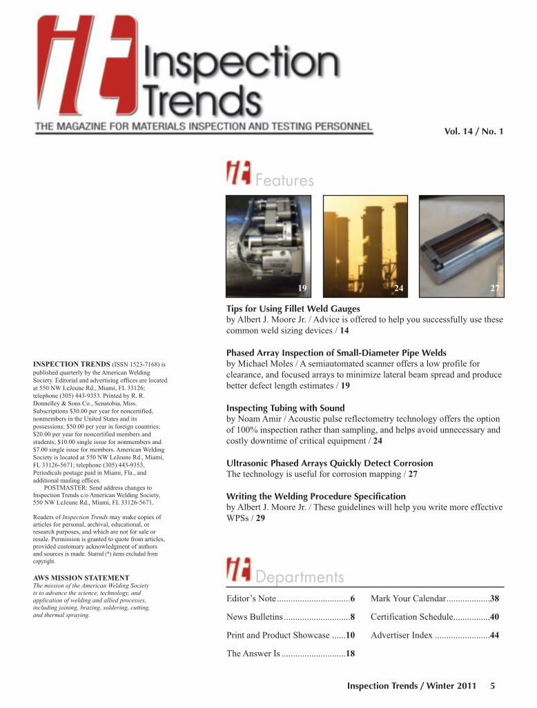
Features
19 24 27
Tips for Using Fillet Weld Gaugesby Albert J. Moore Jr. / Advice is offered to help you successfully use these
common weld sizing devices / 14
Phased Array Inspection of Small-Diameter Pipe Weldsby Michael Moles / A semiautomated scanner offers a low profile for
clearance, and focused arrays to minimize lateral beam spread and produce
better defect length estimates / 19
Inspecting Tubing with Soundby Noam Amir / Acoustic pulse reflectometry technology offers the option
of 100% inspection rather than sampling, and helps avoid unnecessary and
costly downtime of critical equipment / 24
Ultrasonic Phased Arrays Quickly Detect CorrosionThe technology is useful for corrosion mapping / 27
Writing the Welding Procedure Specificationby Albert J. Moore Jr. / These guidelines will help you write more effective
WPSs / 29
DepartmentsEditor’s Note................................6
News Bulletins .............................8
Print and Product Showcase ......10
The Answer Is ............................18
Mark Your Calendar...................38
Certification Schedule................40
Advertiser Index ........................44
Inspection Trends / Winter 2011 5
INSPECTION TRENDS (ISSN 1523-7168) is
published quarterly by the American Welding
Society. Editorial and advertising offices are located
at 550 NW LeJeune Rd., Miami, FL 33126;
telephone (305) 443-9353. Printed by R. R.
Donnelley & Sons Co., Senatobia, Miss.
Subscriptions $30.00 per year for noncertified,
nonmembers in the United States and its
possessions; $50.00 per year in foreign countries;
$20.00 per year for noncertified members and
students; $10.00 single issue for nonmembers and
$7.00 single issue for members. American Welding
Society is located at 550 NW LeJeune Rd., Miami,
FL 33126-5671; telephone (305) 443-9353,
Periodicals postage paid in Miami, Fla., and
additional mailing offices. POSTMASTER: Send address changes to
Inspection Trends c/o American Welding Society,550 NW LeJeune Rd., Miami, FL 33126-5671.
Readers of Inspection Trends may make copies ofarticles for personal, archival, educational, or research purposes, and which are not for sale or resale. Permission is granted to quote from articles,provided customary acknowledgment of authors and sources is made. Starred (*) items excluded fromcopyright.
AWS MISSION STATEMENT
The mission of the American Welding Society is to advance the science, technology, and application of welding and allied processes, including joining, brazing, soldering, cutting, and thermal spraying.
TOC Layout Jan 2011:Layout 1 12/22/10 4:37 PM Page 5
Editor’s NoteBy Mary Ruth Johnsen
PublisherAndrew [email protected]
EditorMary Ruth [email protected]
Associate EditorHoward [email protected]
Associate EditorKristin [email protected]
Production ManagerZaida [email protected]
Senior Production CoordinatorBrenda [email protected]
National Sales DirectorRob [email protected]
Advertising Sales RepresentativeLea Garrigan [email protected]
Senior Advertising Production ManagerFrank [email protected]
Subscriptions RepresentativeEdalia [email protected]
American Welding Society550 NW LeJeune Rd.Miami, FL 33126(800/305) 443-9353
Copyright
Copyright © 2011 by American Welding Society in bothprinted and electronic formats. The Society is not responsible for any statement made or opinion expressedherein. Data and information developed by the authors ofspecific articles are for informational purposes only andare not intended for use without independent, substantiating investigation on the part of potential users.
Inspection Trends / January 20116
Dear Readers,
Who knew there was so much to say
about Welding Procedure Specifications?
Not me. When Al Moore proposed writing
a four-article series on WPSs, I’ll admit I
was somewhat skeptical about whether
there was really enough information to fill
four articles and if the topic would hold
your attention throughout a whole year’s
worth of Inspection Trends. I had some
reservations even though the topic always comes up as an area the ITaudience wants more information about in the reader surveys we’ve
conducted. I should know I need to always listen to you, our readers,
because from all reports you have been very interested in the detailed
articles Moore has written on Welding Procedure Specifications.
I certainly know a lot more about the subject than I did a year ago.
Moore has brought us step by step through the process of preparing
WPSs. First he defined the types of WPSs, then he explained what
essential and nonessential variables are, how to qualify a WPS by
testing, and in this issue how to write a WPS that will help your
company and its welders meet your customer’s needs.
In this issue’s article, Moore makes a statement that I believe sums
up what we all need to do to make our writing clear and understandable
whether we’re preparing a WPS, inspection report, or an article in
Inspection Trends. In the article, Moore’s actually referring to a
numbering system for WPSs, but I think it applies to all writing: “Keep
in mind that a system that has a rational basis is easier to remember and
use.” (The emphasis here is mine.)
We’re covering a wide area in this issue. The articles range from
nitty-gritty topics such as writing WPSs and using fillet weld gauges to
advanced NDE methods such as ultrasonic phased array inspections and
acoustic pulse reflectometry. If you consider Ken Erickson’s reflections
on what the future holds for CWIs on page 18 in “The Answer Is . . .”, I
believe you’ll agree that in the future, CWIs will need to be
knowledgeable about and hold certifications for several NDE
technologies. Many of you are already well-prepared for what the future
will bring because you already hold multiple certifications.
I believe we’re starting off this new year of Inspection Trends with
a lot of valuable information. I hope you can put it to good use.
If you wish to submit an article, or have any questions or
comments, please contact me at (800) 443-9353, ext. 238, or
I also want to wish you all a happy, healthy, and productive new
year. — Mary Ruth Johnsen.
Editor's Note Winter 2011:Layout 1 12/22/10 3:03 PM Page 6

Founded in 1919 to advance the science, technology and application of welding and allied processes includingjoining, brazing, soldering, cutting and thermal spraying.
���������������� ��
���� � ��������� �� �����
�����������������������������
For more information on the course, qualification requirements,certification exams, and test locations, visit our website atwww.aws.org/certification/CRI or call 1-800-443-9353 ext 273.
���������������� ������������������ ����������NDE professionals and current AWS CWIs:
The AWS Certified Radiographic Interpreter training and certification program assures employers and practitionersalike that the principles of radiographic interpretation are reliably applied to the examination of welds. If your jobresponsibilities include reading and interpretation of weld radiographs, this program is for you. You’ll learn proper filmexposure, correct selection of penetrameters, characterization of indications, and use of acceptance criteria asexpressed in the AWS, API, and ASME codes.
NEW! If you are a CWI, certification as an Radiographic Interpreter (CRI) can now exemptyou from your next 9-Year CWI Recertification Exam.
aws cert (cri):FP_TEMP 12/22/10 8:43 AM Page 7
News Bulletins
Inspection Trends / January 20118
Ultrasonic Phased Array Testing Played Part inRescuing Chilean Miners
A company in Edmonton, Alb., Canada, played a role inthe rescue of the 33 miners who were trapped in the San Josecopper and gold mine in Chile. All 33 of the miners wererescued in October 2010 after spending 69 days trapped inthe mine.
Metalogic Inspection Services used its Metaphaseultrasonic phased array testing equipment to inspect thewelds on the metal pipe that was inserted into the shaft thatwas used to reach the miners. The capsule that was used tocarry the workers up to the surface was inserted into the pipe.
“We actually preinspect the weld,” said Quintin Bower,Metalogic’s corporate business development manager,according to a report from the Canadian Broadcasting Center.“So as they are manufacturing the pipe and putting it into theground, we will do a full circumferential scan of the weld.They push it down deeper, and they put another joint in andso forth until they got the complete weld inside the shaft thatthey drilled.”
Bower said the company gathered staff and resourcesfrom Edmonton, Brazil, and Thailand to help with theoperation.
ASQ Manufacturing Outlook Survey ShowsGrowth
The second annual ASQ Manufacturing Outlook Surveyshows the majority of manufacturers are optimistic about aneconomic uptick in 2011 at their organizations — a slightlybrighter outlook than for 2010. The survey was conducted bythe American Society for Quality, Milwaukee, Wis.
The survey results showed 68% of respondentsemployed in the manufacturing sector predict theirorganizations will experience revenue growth. A year ago,64.7% of respondents said revenue would grow in 2010.
The two areas from the survey that showed the mostpromise were in the areas of payroll and operational budgets.Only 18% expect a pay freeze at their organizations in 2011compared to 44.8% in 2010, and 18% predict mandatorybudget cuts this year as compared to 35.2% in 2010.
Of the other options surveyed, respondents anticipate thefollowing:• Expectations of a salary/merit increase (48%).• Organizations will continue to create processes to reduce
costs (47%). That’s down from 61.3% in 2010.• Maintaining current staff levels at their organizations
(42%).• Hiring of additional staff (42%).• No mandatory furlough days (73%). In 2010, 72%
indicated they did not have to take furlough days.The survey questioned whether staff reductions or other
cutbacks implemented in 2010 negatively impacted thequality of the products/services delivered. Thirty-threepercent of respondents believed the quality of their productsand/or services was negatively impacted, and 32% believedquality did not suffer.
Respondents were also asked what one tip they wouldgive to manufacturers to ensure revenue growth in 2011. Thetop four tips, which are similar to those listed in the 2010outlook, are as follows:• Continue to take part in continuous improvement practices,
and increase use of quality processes;• Increase customer satisfaction;• Implement more lean processes;• Reduce costs/eliminate waste.
“Though it appears the manufacturing sector is stillfacing some challenges on the road to full economicrecovery, the incremental gains shown in this survey are verypromising,” said ASQ Chair Peter Andres. “However,organizations still need to focus on and increase customersatisfaction, and implement continuous improvementpractices to remain competitive.”
TÜV SÜD America Offering NDE PersonnelApproval Services
TÜV SÜD America, Inc., Peabody, Mass., a globalinspection and certification services organization, now offersNDE personnel approval services in accordance with thePressure Equipment Directive (PED) (97/23/EC).
The company will act as a recognized third-partyorganization (RTPO) according to Article 13 of the PEDthrough TÜV SÜD Industrie Service GmbH, ensuring thatpersonnel who inspect welds on pressure equipment inCategories III and IV meet all the outlined requirements andhave passed all theoretical and practical exams. Servicesinclude testing by U.S.-based personnel of the applicantsthrough Level IIIs in the respective discipline usingprocedures described in CEN TR 15589. Currently, thecompany is the only Notified Body in North Americaadditionally authorized as an RTPO.
E&E Mfg. Earns A2LA Accreditation
E&E Manufacturing recently earned accreditation by theAmerican Association for Laboratory Accreditation (A2LA).The accreditation covers both ferrous and nonferrous metalsand is to the ISO/IEC 17025:2005 standards.
“In addition to the testing we’ve offered for years, this
News Bulletins Jan IT 2011':Layout 1 12/22/10 2:20 PM Page 8
Inspection Trends / Winter 2011 9
accreditation also includes several new testing services that
will enable us to better serve both existing and new
customers alike,” said President Wes Smith.
The certification entitles E&E to perform a wide range
of tests including hardness, microstructure, case depth,
microetching, macroetching, surface condition, and weld
procedure qualification, as well as nondestructive tests such
as magnetic particle and liquid dye penetrant.
E&E Manufacturing was established in 1962 as a
producer of stampings for the auto industry. Today it has
nearly 500,000 sq ft of production capability at plants in
Plymouth, Mich., and Athens, Tenn. It still serves the auto
industry as well as other industrial markets and the military.
Imperium Selects VP of Global Sales, NDTProducts
Imperium, Inc., Beltsville, Md., a developer and
manufacturer of ultrasound imaging cameras for
nondestructive examination, has hired Bruce Stetler as vice
president global sales, NDT products.
Stetler has been in the NDE industry for more than 27
years, most recently as midwest regional sales manager and
west coast regional sales manager for Olympus. He has been
a member of AWS for more than ten years and a member of
ASNT for 25 years.
FILLET WELD GAUGESFROM 1/8” TO 3”
For info go to www.aws.org/ad-index For info go to www.aws.org/ad-index
For
info
go
to w
ww
.aw
s.or
g/ad
-ind
ex
News Bulletins Jan IT 2011':Layout 1 12/22/10 2:20 PM Page 9

Print and Product Showcase
Inspection Trends / January 201110
UV Light Source Offers Hands-FreeOperation
The Spectroline® EK-3000
EagleEye™ UV-A/white light LED
inspection kit features a palm-sized,
cool-running inspection lamp. The
lamp features two ultrahigh-intensity
UV-A (365 nm) LEDs that are useful
for NDE and mining inspection, plus a
three-LED white light assembly for
general illumination. An adjustable
strap allows the lamp to be worn on a
hard hat or directly on the head for
hands-free operation. A lamp
mount/sprayer attachment permits the
lamp and a spray can to be mounted
together for single-handed fluorescent
yoke inspection. The lamp produces a
nominal steady-state UV-A intensity of
5500 μW/cm2 at 15 in. A built-in fan
keeps the lamp cool to maintain
optimum UV-A intensity during
prolonged inspections. It includes a
rechargeable lithium-ion battery that
provides up to 45 min of continuous
inspection between charges. Also
included is a lanyard, two replacement
splash guards with integral particulate
filters, three batteries, a battery
charging cradle, UV-absorbing
spectacles, and carrying case.
Spectronics Corp.
www.spectroline.com
(800) 274-8888
Phased Array Instrument Provides Fast Data Recording
The Veo 16:64 phased array
instrument is useful for pipeline weld
inspection, corrosion mapping, and
aerospace and composite testing. The
instrument offers fast data recording, a
simple-to-use interface, and rugged
housing. Its display features full 3-D
views of the user’s test setup including
probes, wedges, the weld, and
Print & Product Winter 2011 IT:Layout 1 12/22/10 2:24 PM Page 10

Inspection Trends / Winter 2011 11
geometry, with phased array beams. It
provides quick A-scan recording and
reporting functionality and two
separate conventional channels provide
simultaneous phased array and time-of-
flight diffraction scanning to speed up
inspection and ensure correct data
referencing for improved defect
characterization.
Sonatest
www.sonatest.com
(210) 697-0335
Portable Pipe Inspection CameraFits in Tight Spaces
The Pilit-Mini™ inspection
camera fits in pipes 3⁄4 in. and larger. It
runs on battery or AC power, offers a
30-m fiberglass/stainless steel
reinforced push rod with watertight
connectors, and features a robust
design that withstands the harsh
conditions found with pipe inspection.
It is lightweight, portable, and fits into
tight spaces. The push rod is highly
flexible, allowing it to easily pass
around bends. It offers a wireless LCD
screen that presents crisp color images.
Advanced Inspection Technologies
www.aitproducts.com
(321) 610-8977
Articulating Video Borescopes Feature Stand-Alone Image Processing
The company’s VJ-Advanced®
Series articulating video borescope
ASNT,Bringing Thousands of MindsTo NDT Matters, Including Yours.
Join the Professional SocietyThat Brings the NDT Community & Its Resources To You.
The American Society for Nondestructive Testing
Serving the Profession,
Creating a Safer World. www.asnt.org
For info go to www.aws.org/ad-index
Print & Product Winter 2011 IT:Layout 1 12/22/10 2:25 PM Page 11
features on-board (stand-alone) image
processing and battery-powered,
portable operation. It features a high-
resolution 3.5-in. TFT LCD screen
with a removable sun visor and 2×digital zoom function. It has a
waterproof, 0.272-in. insertion tube
and features braided stainless steel
sheathing for resistance to oil, fuel, and
3.5% concentrated saltwater. The
camera tip displays the temperature
with lapse-time recording and
temperature alarm display. It features a
thumb-activated 360-deg joystick,
weighs 20 oz, and includes four high-
intensity LEDs with adjustable
brightness control.
Titan Tool Supply, Inc.
www.titantoolsupply.com
(716) 873-9907
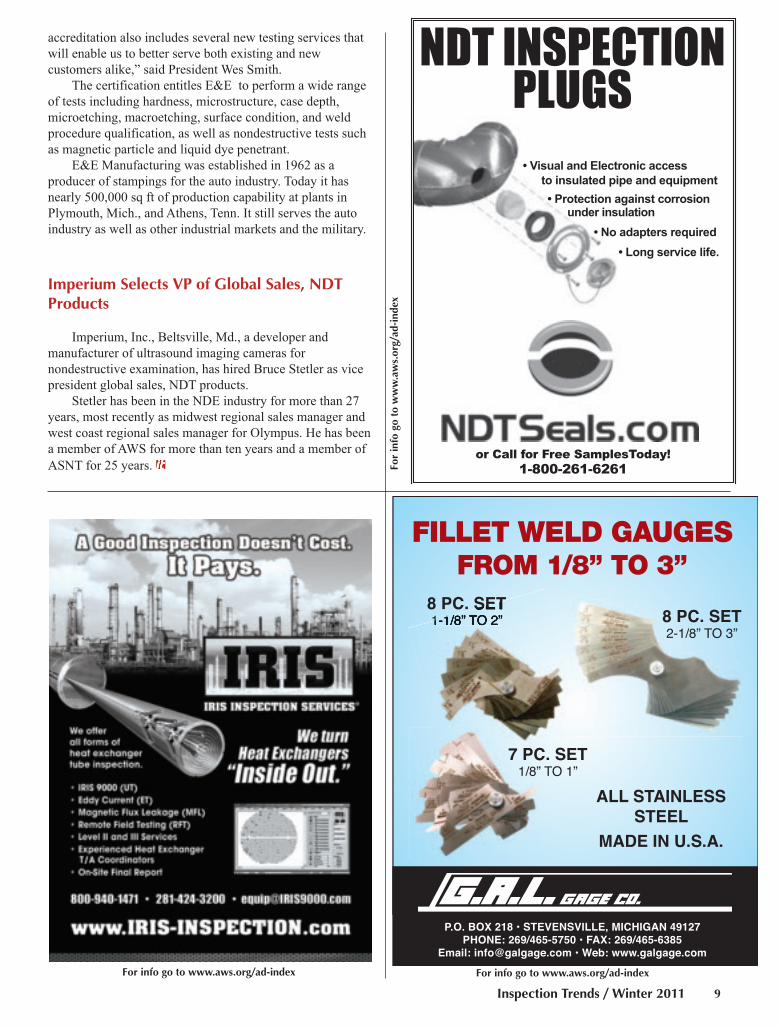
Alloy Sorter Quickly Identifies Metals
The TE-3000 thermoelectric alloy
sorter takes 1 s per test to identify
materials such as steels, nickel,
aluminum, titanium alloys, stainless
steels, superalloys, specialty steels, tool
steels, low-alloy steels, and common
steels. Other applications include the
detection of platings and plasma
coatings, in-line and part testing, and
scrap sorting. The instrument includes
interchangeable probe tips for
improved test metal contact, carry case,
international voltage regulator, and
data logging system.
Koslow Scientific Co.
www.koslow.com
(800) 556-7569
3-D Phase Measurement Technology Paired with Video Borescope
The company has paired its XLG3
video borescope with 3-D phase
measurement technology to increase
Inspection Trends / January 201112
Print & Product Winter 2011 IT:Layout 1 12/22/10 2:25 PM Page 12

accuracy and productivity in aerospace
and rotating equipment applications.
The 3-D measurement eliminates the
need to change the probe tip to capture
the measurement, which streamlines
the inspection process. The 3-D phase
measurement offers Profile Views, a
cross-section view of a portion of the
surface. With Profile View, the
inspector can rotate and zoom to get a
more accurate view of the defect.
GE Sensing & Inspection Technologies
www.geinspectiontechnologies.com
(800) 833-9438
System Displays and Records Real-Time Video during Pipe Inspections
The ClipStream™ captures up to
16 GB (approximately 12 h) of AVI
video and JPEG still images to a micro
SD card. Recorded footage can be
viewed directly on the system’s 3.6-in.
color LCD or transferred to a computer
or smart phone by ejecting the card or
tethering via USB. It clamps in seconds
to the pole of the company’s
QuickView® zoom survey camera and
displays and records real-time video
during pipe and manhole inspections.
In wireless mode, ClipStream™
transmits video to any monitor on the
same frequency, which means several
people can view the same video from
different locations. When tuned to
different frequencies, multiple units
can be used in the same area without
interference. The system accepts NTSC
or PAL video input via a BNC
connector, and outputs analog video via
a phone jack. It runs on four AA
batteries, or connects to mains power
using an optional AC adapter.
Envirosight LLC
www.envirosight.com
(866) 936-8476
Inspection Trends / Winter 2011 13
For info go to www.aws.org/ad-index
Official Interpretation:
Aluminum Brazing
Subject: Temperature Uniformity Re-quirements Code Edition: AWS C3.7M/C3.7:2005Code Provision: Page 4, Subclause 5.3.2(Temperature Uniformity Requirements)
Inquiry: Do salt baths for brazing alu-minum having a solidus of less than1120°F have to meet a ±5°F, SAE/AMS2750, Pyrometry, Class 1 temperature uni-formity requirement?
Response: Yes.
Print & Product Winter 2011 IT:Layout 1 12/22/10 2:26 PM Page 13

FeatureBy
Inspection Trends / January 201114
By Albert J. Moore Jr.
Other than the measuring tape, the
fillet weld gauge is the most used
measuring device in the welding
inspector’s kit. That is understandable
considering the majority of the welds
deposited are fillet welds. Yet many
people measure the size of the fillet
weld incorrectly.
The principle of the fillet gauge is
pretty simple. The fillet weld has a
cross section that is essentially a
triangle. If the two members being
joined are at right angles to each other,
the cross section of the fillet weld
resembles an isosceles right triangle —
Fig. 1. One basic assumption is that the
fillet weld is fused to the joint root, but
not necessarily beyond. With those two
assumptions in place, i.e., the cross
section of the fillet weld is an isosceles
right triangle and it has fusion to the
root, we can establish a relationship
between the length of the fillet weld
legs and the theoretical throat. We need
to know the dimension of the throat
because it is the “weak link”; that is, it
represents the shortest failure path
through the cross section of the weld.
With the two conditions noted in place,
we can define the size of the fillet weld
as the largest inscribed isosceles right
triangle.
Inspectors usually use a leaf-type
fillet weld gauge to measure the size of
fillet welds. The gauges come as a set
of individual gauges that are used to
size fillet welds. I did not say
“measure” fillet welds because the
leaf-type gauge only indicates whether
the weld is less than, larger than, or the
same size as the gauge.
The inspector checks the size of
the actual weld by using one or more
gauges to compare the size of the weld
to the size of the individual gauges.
The gauges typically come in 1⁄16-in.
increments for weld sizes ½ in. and
smaller, and in 1⁄8-in. increments for
sizes of 5⁄8 in. and larger.
The basic leaf-type gauge has two
ends, one for sizing the weld leg and
the other for checking the throat
dimension. Well, that’s not exactly
accurate. The gauge does not directly
measure or size the throat. Instead, it
sizes the throat for the equivalent leg
size for an isosceles right triangle.
As shown in Fig. 2, the gauge has
two ends. The left end is used to size
the fillet weld leg; the right end is used
to size the weld throat.
If we were to check an ideal fillet
weld, one that is a perfect isosceles
right triangle that matched the size of
the gauge, both the weld legs would be
exactly 1⁄2 in. The throat of the fillet
weld would measure exactly 0.354 in.
(0.707 × 0.5). Rather than imprinting
0.354 on the right end of the gauge, the
manufacturers imprint it with 1⁄2
because the fillet throat is the proper
size for a fillet weld with 1⁄2-in. legs.
That saves the inspector the time
needed to calculate the required throat
dimension for each leg dimension.
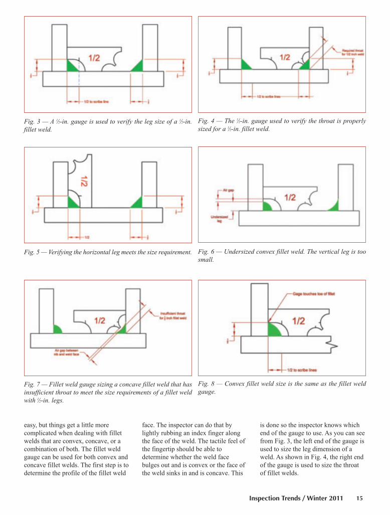
Figures 3 and 4 show that the fillet
weld legs are exactly ½-in. each.
Figure 5 depicts how to measure the
vertical fillet leg. As indicated by the
figure, the gauge has to be turned to
verify the horizontal fillet leg is the
proper size. After all, the two legs may
not be the same size by design or as
dictated by the welder’s skill, so both
the horizontal and vertical legs must be
checked.
Checking the perfect fillet weld is
Tips for Using Fillet Weld Gauges
The following advice will help you consistently size fillet welds properly
Fig. 1 — A typical fillet weld, such as the one shown here, hasa cross section that resembles an isosceles right triangle.
Fig. 2 — Example of a gauge used to size 1⁄2-in. fillet welds.
Moore Fillet Gauge IT Winter 2011:Layout 1 12/22/10 1:14 PM Page 14
Inspection Trends / Winter 2011 15
easy, but things get a little more
complicated when dealing with fillet
welds that are convex, concave, or a
combination of both. The fillet weld
gauge can be used for both convex and
concave fillet welds. The first step is to
determine the profile of the fillet weld
face. The inspector can do that by
lightly rubbing an index finger along
the face of the weld. The tactile feel of
the fingertip should be able to
determine whether the weld face
bulges out and is convex or the face of
the weld sinks in and is concave. This
is done so the inspector knows which
end of the gauge to use. As you can see
from Fig. 3, the left end of the gauge is
used to size the leg dimension of a
weld. As shown in Fig. 4, the right end
of the gauge is used to size the throat
of fillet welds.
Fig. 3 — A 1⁄2-in. gauge is used to verify the leg size of a 1⁄2-in.fillet weld.
Fig. 5 — Verifying the horizontal leg meets the size requirement. Fig. 6 — Undersized convex fillet weld. The vertical leg is toosmall.
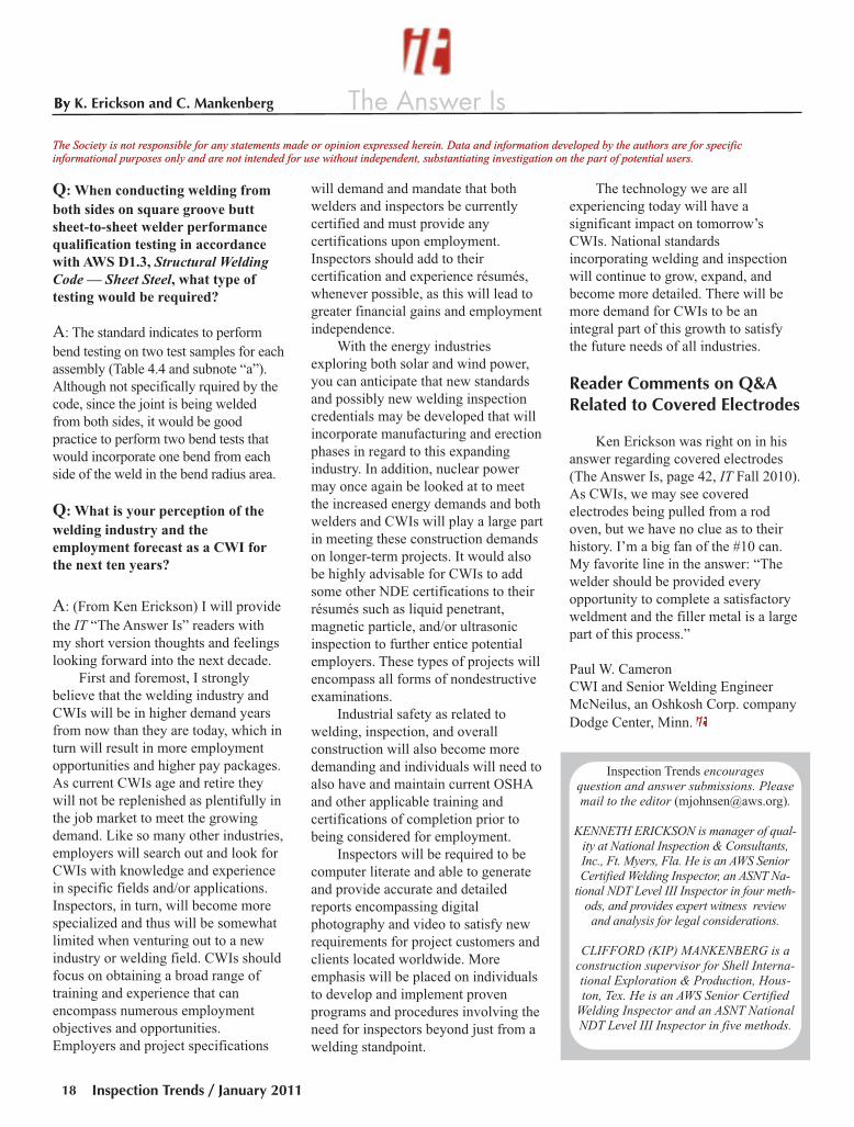
Fig. 7 — Fillet weld gauge sizing a concave fillet weld that hasinsufficient throat to meet the size requirements of a fillet weldwith 1⁄2-in. legs.
Fig. 8 — Convex fillet weld size is the same as the fillet weldgauge.
Fig. 4 — The 1⁄2-in. gauge used to verify the throat is properlysized for a 1⁄2-in. fillet weld.
Moore Fillet Gauge IT Winter 2011:Layout 1 12/27/10 2:21 PM Page 15

Inspection Trends / January 201116
To reiterate, fillet weld gauges do
not measure fillet welds. The gauges
are used to determine whether the weld
is smaller than, larger than, or the exact
size of the gauge being used. The set of
leaves of the fillet weld gauges are a
collection of “go/no-go” gauges. The
inspector sizes the fillet weld by
comparing the size of the weld to the
size of several gauges until the
inspector finds a gauge where the weld
is slightly larger than the gauge.
Most welding standards include a
statement to the effect the required
weld size is as specified by the welding
symbol. Dig a little deeper into the
welding standard, and there may be
provisions permitting a weld to be
slightly smaller by some fraction or
percentage of the specified weld size.
The inspector’s task is to determine
what the smallest permitted weld size
is and then verify all the fillet welds are
at least as big as the smallest weld size
permitted. Let us say the welding
symbol specifies the weld size as 9⁄16 in.
The welding standard allows the weld
to under run the specified weld size by1⁄16 in. The smallest weld permitted
would be the specified size minus the
allowable under run or 9⁄16 – 1⁄16 = ½ in.
The inspector would select the ½-in.
fillet weld gauge and check the weld
legs (if the weld is convex) or the weld
throat (if the fillet weld is concave).
The welds would then be declared
undersized if the welds were less than
½ in. or they would be accepted if they
were ½ in. or larger.
The following figures depict the
conditions the inspector might find
during an inspection. Figure 6 depicts
an undersized convex fillet weld, and
Fig. 7 shows a concave fillet weld that
is undersized under the defined
constraints.
Figures 8 and 9 depict fillet gauges
sizing welds that meet the minimum
size requirement. Both the convex and
concave fillet welds are acceptable if
both legs of the convex fillet weld are
found to be the proper size or in the
latter case, the throat is the proper size.
Figure 10 shows a convex weld
and a concave weld that are larger than
the ½-in. fillet weld gauge used to
check the weld sizes.
Let me now interject my personal
philosophy on how to verify the size of
a fillet weld when using the leaf-type
fillet gauge. In the example provided,
we determined the smallest acceptable
weld size is ½ in. based on the
stipulations of the welding standard.
We also noted that the gauges are
available in 1⁄16-in. increments up to ½
in. I do not interpolate the weld size
when I use these fillet weld gauges. To
put it another way, the weld is either
smaller than the weld gauge, the same
size as the weld gauge, or the weld is
larger than the size of the gauge being
used. I do not round the “measured”
weld size up to ½ in. if the weld
appears to be more than 15⁄32 in., i.e., 1⁄32
Fig. 9 — Concave fillet weld size is the same as the fillet weldgauge.
Fig. 10 — The convex (top) and concave fillet welds are largerthan the size indicated by the fillet weld gauge.
Fig. 11 — Modified fillet weld gauge used for measuring the legof the fillet weld in a skewed joint.
Moore Fillet Gauge IT Winter 2011:Layout 1 12/27/10 2:21 PM Page 16

Inspection Trends / Winter 2011 17
in. less than the ½-in. fillet size. The
amount of under run permitted has
already been taken into consideration.
When reporting the size of a fillet
weld, I do not report the average size
for the continuous fillet weld. If the
size varies from 3⁄8 to ¼ in., I do not
report it as 5⁄16 in. It is reported as ¼ in.
and the length is discounted if it is less
than ¼ in. due to the presence of an
unfilled crater, etc. As an inspector, I
report my findings and simply state the
weld does not comply with the size
specified by the welding symbol. When
working under the auspices of AWS
D1.1, Structural Welding Code —Steel, it is the Engineer’s prerogative to
accept undersized welds if it is
determined they are suitable for the
intended service. Other welding
standards may have different
provisions, such as no under run (same
as undersized) is permitted, in which
case the weld has to be at least as big
as what is specified on the drawing.
There is one rather large fly in the
ointment. The fillet weld gauges in this
article work fine when the members are
at right angles to each other, but what
happens with welded joints that are
skewed at an angle other than 90 deg?
The gauge does not fit into the corner.
There are gauges available from at
least one vendor that are a slightly
modified fillet gauge. This modified
gauge is depicted in Fig. 11.
You can also make that type of
gauge yourself. I usually make gauges
like that shown in Fig. 11 out of heavy
banding straps that I salvage from the
scrap bin. The modified gauge is fine
for measuring the leg dimension of a
convex fillet weld, but it is not
appropriate for a concave fillet weld.
I’ll leave it up to you to design your
own gauge for that situation.
Statement of Ownership, Management, and Circulation for U.S. Postal Service (Required by U.S.C. 3685)
1. TITLE OF PUBLICATION: Inspection Trends 2. PUBLICATION NO.: ISSN 1523-71683. DATE OF FILING: September 22, 2010 4. FREQUENCY OF ISSUE: Quarterly5. NO. OF ISSUES PUBLISHED ANNUALLY: 4 6. ANNUAL SUBSCRIPTION: $30.007. MAILING ADDRESS OF KNOWN OFFICE OF PUBLICATION: 550 NW LeJeune Rd., Miami, Miami-Dade County, Florida 331268. MAILING ADDRESS OF THE HEADQUARTERS OR GENERAL BUSINESS OFFICES OF THE PUBLISHERS:
550 NW LeJeune Rd., Miami, Miami-Dade County, Florida 331269. NAMES AND COMPLETE ADDRESS OF PUBLISHER, EDITOR, AND MANAGING EDITOR:
PUBLISHER: Andrew Cullison, AWS, 550 NW LeJeune Rd., Miami, Florida 33126EDITOR: Mary Ruth Johnsen, AWS, 550 NW LeJeune Rd., Miami, Florida 33126
10. OWNER: NAME: American Welding Society, Inc. ADDRESS: 550 NW LeJeune Rd., Miami, Florida 3312611. KNOWN BONDHOLDERS, MORTGAGEES, AND OTHER SECURITY HOLDERS OWNING OR HOLDING 1 PERCENT OR MORE
OF TOTAL AMOUNT OF BONDS, MORTGAGES, OR OTHER SECURITIES: None12. The purpose, function, and nonprofit status of this organization and the exempt status for Federal income tax purposes:
Has not changed during preceding 12 months13. Publication Title: Inspection Trends 14. Issue Date for Circulation Data Below: Fall October 201015. EXTENT AND NATURE OF CIRCULATION:
Average No. Copies Each Actual No. Copies of Issue during Preceding Single Issue Published
12 Months Nearest to Filing Date
A. Total No. Copies Printed (Net Press Run) 22,850 23,100B. Paid and/or Requested Circulation
1. Paid/Requested Outside-County Mail Subscriptions Stated on Form 3541 22,243 22,4332. Paid In-County Subscriptions Stated on Form 3541 None None3. Sales through Dealers and Carriers, None None
Street Vendors, Counter Sales, and Other Non-USPS Paid Distribution4. Other Classes Mailed through the USPS None None
C. Total Paid/Requested Circulation 22,243 22,433D. Free Distribution by Mail (Samples, Complimentary and Other Free)
1. Outside-County as Stated on Form 3541 81 792. In-County as Stated on Form 3541 None None3. Other Classes Mailed through the USPS None None4. Free Distribution Outside the Mail (Carriers or Other Means) None None
E. Total Free Distribution 81 79F. Total Distribution 22,324 22,512G. Copies Not Distributed 526 588H. Total 22,850 23,100I. Percent Paid and/or Requested Circulation 99.6% 99.6%
16. Statement of Ownership will be printed in the Winter January 2011 issue of this publication.I certify that the statements made by above are correct and complete:Andrew Cullison, Publisher
ALBERT J. MOORE JR.([email protected]) is vice presi-dent, Marion Testing & Inspection, Can-ton, Conn. He is an AWS Senior CertifiedWelding Inspector, an ASNT ACCP NDT
Level III, and a member of the AWS Certi-fication Committee and the Committee on
Methods of Inspection of Welds.
Don't pay for travel or accommodations for
intense one week courses...ever again
www.
worl
dspe
c.or
g
Fully online NDT training to meet global standards!
Register today and save $100 dollars instantly.
Enter aws59c2 in the discount code box
YOURCLASSROOMAWAITS...
For info go to www.aws.org/ad-index
Moore Fillet Gauge IT Winter 2011:Layout 1 12/27/10 2:21 PM Page 17
The Answer IsBy
Inspection Trends / January 201118
The Society is not responsible for any statements made or opinion expressed herein. Data and information developed by the authors are for specificinformational purposes only and are not intended for use without independent, substantiating investigation on the part of potential users.
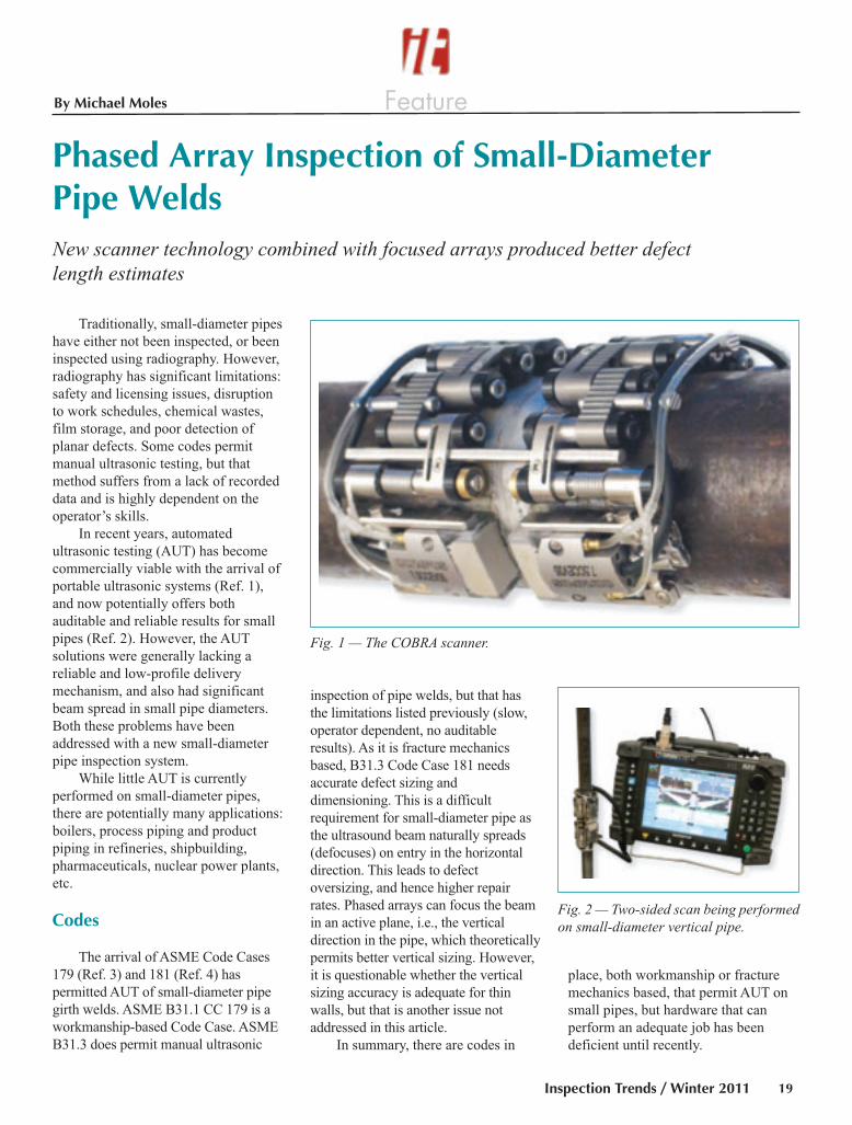
By K. Erickson and C. Mankenberg
Q: When conducting welding from
both sides on square groove butt
sheet-to-sheet welder performance
qualification testing in accordance
with AWS D1.3, Structural WeldingCode — Sheet Steel, what type of
testing would be required?
A: The standard indicates to perform
bend testing on two test samples for each
assembly (Table 4.4 and subnote “a”).
Although not specifically rquired by the
code, since the joint is being welded
from both sides, it would be good
practice to perform two bend tests that
would incorporate one bend from each
side of the weld in the bend radius area.
Q: What is your perception of the
welding industry and the
employment forecast as a CWI for
the next ten years?
A: (From Ken Erickson) I will provide
the IT “The Answer Is” readers with
my short version thoughts and feelings
looking forward into the next decade.
First and foremost, I strongly
believe that the welding industry and
CWIs will be in higher demand years
from now than they are today, which in
turn will result in more employment
opportunities and higher pay packages.
As current CWIs age and retire they
will not be replenished as plentifully in
the job market to meet the growing
demand. Like so many other industries,
employers will search out and look for
CWIs with knowledge and experience
in specific fields and/or applications.
Inspectors, in turn, will become more
specialized and thus will be somewhat
limited when venturing out to a new
industry or welding field. CWIs should
focus on obtaining a broad range of
training and experience that can
encompass numerous employment
objectives and opportunities.
Employers and project specifications
will demand and mandate that both
welders and inspectors be currently
certified and must provide any
certifications upon employment.
Inspectors should add to their
certification and experience résumés,
whenever possible, as this will lead to
greater financial gains and employment
independence.
With the energy industries
exploring both solar and wind power,
you can anticipate that new standards
and possibly new welding inspection
credentials may be developed that will
incorporate manufacturing and erection
phases in regard to this expanding
industry. In addition, nuclear power
may once again be looked at to meet
the increased energy demands and both
welders and CWIs will play a large part
in meeting these construction demands
on longer-term projects. It would also
be highly advisable for CWIs to add
some other NDE certifications to their
résumés such as liquid penetrant,
magnetic particle, and/or ultrasonic
inspection to further entice potential
employers. These types of projects will
encompass all forms of nondestructive
examinations.
Industrial safety as related to
welding, inspection, and overall
construction will also become more
demanding and individuals will need to
also have and maintain current OSHA
and other applicable training and
certifications of completion prior to
being considered for employment.
Inspectors will be required to be
computer literate and able to generate
and provide accurate and detailed
reports encompassing digital
photography and video to satisfy new
requirements for project customers and
clients located worldwide. More
emphasis will be placed on individuals
to develop and implement proven
programs and procedures involving the
need for inspectors beyond just from a
welding standpoint.
The technology we are all
experiencing today will have a
significant impact on tomorrow’s
CWIs. National standards
incorporating welding and inspection
will continue to grow, expand, and
become more detailed. There will be
more demand for CWIs to be an
integral part of this growth to satisfy
the future needs of all industries.
Reader Comments on Q&ARelated to Covered Electrodes
Ken Erickson was right on in his
answer regarding covered electrodes
(The Answer Is, page 42, IT Fall 2010).
As CWIs, we may see covered
electrodes being pulled from a rod
oven, but we have no clue as to their
history. I’m a big fan of the #10 can.
My favorite line in the answer: “The
welder should be provided every
opportunity to complete a satisfactory
weldment and the filler metal is a large
part of this process.”
Paul W. Cameron
CWI and Senior Welding Engineer
McNeilus, an Oshkosh Corp. company
Dodge Center, Minn.
Inspection Trends encouragesquestion and answer submissions. Pleasemail to the editor ([email protected]).
KENNETH ERICKSON is manager of qual-ity at National Inspection & Consultants,Inc., Ft. Myers, Fla. He is an AWS SeniorCertified Welding Inspector, an ASNT Na-
tional NDT Level III Inspector in four meth-ods, and provides expert witness reviewand analysis for legal considerations.
CLIFFORD (KIP) MANKENBERG is aconstruction supervisor for Shell Interna-tional Exploration & Production, Hous-ton, Tex. He is an AWS Senior Certified
Welding Inspector and an ASNT NationalNDT Level III Inspector in five methods.
The Society is not responsible for any statements made or opinion expressed herein. Data and information developed by the authors are for specificinformational purposes only and are not intended for use without independent, substantiating investigation on the part of potential users.
The Answer Is Jan IT 2011:Layout 1 12/22/10 2:13 PM Page 18
FeatureBy Michael Moles
Traditionally, small-diameter pipes
have either not been inspected, or been
inspected using radiography. However,
radiography has significant limitations:
safety and licensing issues, disruption
to work schedules, chemical wastes,
film storage, and poor detection of
planar defects. Some codes permit
manual ultrasonic testing, but that
method suffers from a lack of recorded
data and is highly dependent on the
operator’s skills.
In recent years, automated
ultrasonic testing (AUT) has become
commercially viable with the arrival of
portable ultrasonic systems (Ref. 1),
and now potentially offers both
auditable and reliable results for small
pipes (Ref. 2). However, the AUT
solutions were generally lacking a
reliable and low-profile delivery
mechanism, and also had significant
beam spread in small pipe diameters.
Both these problems have been
addressed with a new small-diameter
pipe inspection system.
While little AUT is currently
performed on small-diameter pipes,
there are potentially many applications:
boilers, process piping and product
piping in refineries, shipbuilding,
pharmaceuticals, nuclear power plants,
etc.
Codes
The arrival of ASME Code Cases
179 (Ref. 3) and 181 (Ref. 4) has
permitted AUT of small-diameter pipe
girth welds. ASME B31.1 CC 179 is a
workmanship-based Code Case. ASME
B31.3 does permit manual ultrasonic
inspection of pipe welds, but that has
the limitations listed previously (slow,
operator dependent, no auditable
results). As it is fracture mechanics
based, B31.3 Code Case 181 needs
accurate defect sizing and
dimensioning. This is a difficult
requirement for small-diameter pipe as
the ultrasound beam naturally spreads
(defocuses) on entry in the horizontal
direction. This leads to defect
oversizing, and hence higher repair
rates. Phased arrays can focus the beam
in an active plane, i.e., the vertical
direction in the pipe, which theoretically
permits better vertical sizing. However,
it is questionable whether the vertical
sizing accuracy is adequate for thin
walls, but that is another issue not
addressed in this article.
In summary, there are codes in
place, both workmanship or fracture
mechanics based, that permit AUT on
small pipes, but hardware that can
perform an adequate job has been
deficient until recently.
Inspection Trends / Winter 2011 19
Phased Array Inspection of Small-Diameter Pipe WeldsNew scanner technology combined with focused arrays produced better defect length estimates
Fig. 1 — The COBRA scanner.
Fig. 2 — Two-sided scan being performedon small-diameter vertical pipe.
Moles Feature Winter 2011:Layout 1 12/22/10 2:58 PM Page 19
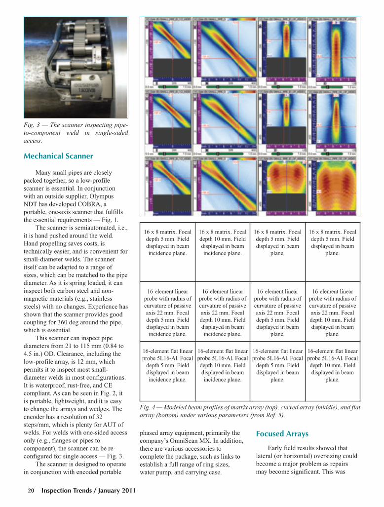
Mechanical Scanner
Many small pipes are closely
packed together, so a low-profile
scanner is essential. In conjunction
with an outside supplier, Olympus
NDT has developed COBRA, a
portable, one-axis scanner that fulfills
the essential requirements — Fig. 1.
The scanner is semiautomated, i.e.,
it is hand pushed around the weld.
Hand propelling saves costs, is
technically easier, and is convenient for
small-diameter welds. The scanner
itself can be adapted to a range of
sizes, which can be matched to the pipe
diameter. As it is spring loaded, it can
inspect both carbon steel and non-
magnetic materials (e.g., stainless
steels) with no changes. Experience has
shown that the scanner provides good
coupling for 360 deg around the pipe,
which is essential.
This scanner can inspect pipe
diameters from 21 to 115 mm (0.84 to
4.5 in.) OD. Clearance, including the
low-profile array, is 12 mm, which
permits it to inspect most small-
diameter welds in most configurations.
It is waterproof, rust-free, and CE
compliant. As can be seen in Fig. 2, it
is portable, lightweight, and it is easy
to change the arrays and wedges. The
encoder has a resolution of 32
steps/mm, which is plenty for AUT of
welds. For welds with one-sided access
only (e.g., flanges or pipes to
component), the scanner can be re-
configured for single access — Fig. 3.
The scanner is designed to operate
in conjunction with encoded portable
phased array equipment, primarily the
company’s OmniScan MX. In addition,
there are various accessories to
complete the package, such as links to
establish a full range of ring sizes,
water pump, and carrying case.
Focused Arrays
Early field results showed that
lateral (or horizontal) oversizing could
become a major problem as repairs
may become significant. This was
Inspection Trends / January 201120
16 x 8 matrix. Focal
depth 5 mm. Field
displayed in beam
incidence plane.
16 x 8 matrix. Focal
depth 10 mm. Field
displayed in beam
incidence plane.
16 x 8 matrix. Focal
depth 5 mm. Field
displayed in beam
plane.
16 x 8 matrix. Focal
depth 5 mm. Field
displayed in beam
plane.
16-element linear
probe with radius of
curvature of passive
axis 22 mm. Focal
depth 5 mm. Field
displayed in beam
incidence plane.
16-element linear
probe with radius of
curvature of passive
axis 22 mm. Focal
depth 10 mm. Field
displayed in beam
incidence plane.
16-element linear
probe with radius of
curvature of passive
axis 22 mm. Focal
depth 5 mm. Field
displayed in beam
plane.
16-element linear
probe with radius of
curvature of passive
axis 22 mm. Focal
depth 10 mm. Field
displayed in beam
plane.
16-element flat linear
probe 5L16-Al. Focal
depth 5 mm. Field
displayed in beam
incidence plane.
16-element flat linear
probe 5L16-Al. Focal
depth 10 mm. Field
displayed in beam
incidence plane.
16-element flat linear
probe 5L16-Al. Focal
depth 5 mm. Field
displayed in beam
plane.
16-element flat linear
probe 5L16-Al. Focal
depth 10 mm. Field
displayed in beam
plane.
Fig. 3 — The scanner inspecting pipe-to-component weld in single-sidedaccess.
Fig. 4 — Modeled beam profiles of matrix array (top), curved array (middle), and flatarray (bottom) under various parameters (from Ref. 5).
Moles Feature Winter 2011:Layout 1 12/22/10 2:58 PM Page 20

particularly important for smaller-
diameter pipes, as beam spread was
more significant.
Initially, an R&D project was
defined to evaluate the possible
solutions to beam spread with phased
array units: matrix (2-D) arrays,
mechanically curved arrays, or any
combinations. Both matrix and curved
arrays offer practical solutions for
focusing in both axial and
circumferential directions. Modeling
was performed using PASS to
determine the relative merits (Ref. 5).
Modeling showed that only two
curvatures were required to cover
essentially all small pipe diameters,
independent of wall thickness. The
larger radius curved array was
manufactured and tested on known
reflectors, and compared with a
standard flat (unfocused) array on
pipes of 70 and 38 mm diameter. The
summary results follow, and are
compared with flat arrays.
Figure 4 shows the modeled
results, with beam profiles displayed in
both beam axis and cross section.
Comparing the images in the third
(last) row with either the first or second
row, it was immediately clear that the
flat, unfocused beam had significantly
worse beam spread than either the
matrix array or the curved array. Wall
thickness had been demonstrated as
relatively unimportant since multiple
skips were required for thinner walls,
so beam paths tended to be quite
constant. (Note that PASS cannot
simulate the field with a beam skip, so
the OD field is calculated by ignoring
the pipe ID reflection and by just
considering total metal path.)
There was no obvious advantage
in using the matrix probe over a linear
array probe with an optimized radius of
curvature. Matrix arrays would be
more expensive and complex to
implement. Curved arrays can be
implemented with no extra hardware or
software, unlike matrix arrays.
Subsequent modeling with a 10-MHz
linear array confirmed these results for
25-, 30-, 50-, and 75-mm diameters.
In summary, the modeling showed
that one probe with 40-mm radius of
curvature is suitable for pipe with an
OD greater than 25 mm, and one probe
with 30-mm radius of curvature for
pipe OD less than 25 mm. Two curved
arrays effectively covered all pipe
diameters.
Experimental Confirmation ofModeling Results
Selected for testing were two pipes
in sizes 2.75 in. (70 mm) and 1.5 in.
(38 mm). Two wedges were contoured
to match the pipe diameters, as per
standard practice. Appropriate notches
and holes were used as reflectors. The
Inspection Trends / Winter 2011 21
Fig. 5 — Detection of the 6.9-mm-long notch using the flat and curved probes (single skip) on 70-mm pipe. A — Flat probe. Themeasured notch length is 9.6 mm. B — curved probe. The measured notch length is 7.1 mm.
Fig. 6 — Detection of the OD end of the 1-mm through hole with the flat and curved probes (double skip) on 38-mm pipe. A —Flat probe. The measured size is 10 mm. B — focused probe. The measured size is 3.6 mm.
A
A
B
B
Moles Feature Winter 2011:Layout 1 12/22/10 2:59 PM Page 21
notches and holes were scanned with
an OmniScan MX using typical phased
array inspection procedures based on
S-scans. The same setup was used for
the two probes except the gain was
necessarily reduced for the curved
probe. The 6-dB drop criterion was
used for sizing.
Figures 5 and 6 show sample scan
results from the 70- and 38-mm pipes,
comparing flat and focused arrays.
All the calibration reflectors in the
two tubes showed consistent results:
smaller-diameter tubes gave more
severe defocusing (beam spread) than
larger diameters, and focused arrays
gave much better lateral sizing results
than flat arrays.
Inspection Trends / January 201122
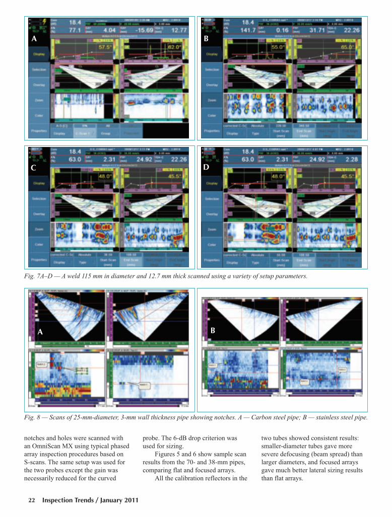
Fig. 7A–D — A weld 115 mm in diameter and 12.7 mm thick scanned using a variety of setup parameters.
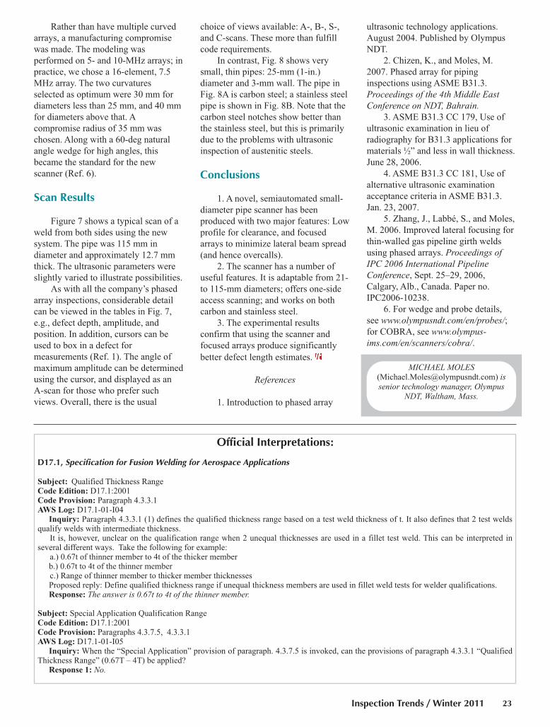
Fig. 8 — Scans of 25-mm-diameter, 3-mm wall thickness pipe showing notches. A — Carbon steel pipe; B — stainless steel pipe.
A B
C D
A B
Moles Feature Winter 2011:Layout 1 12/22/10 2:59 PM Page 22
Rather than have multiple curved
arrays, a manufacturing compromise
was made. The modeling was
performed on 5- and 10-MHz arrays; in
practice, we chose a 16-element, 7.5
MHz array. The two curvatures
selected as optimum were 30 mm for
diameters less than 25 mm, and 40 mm
for diameters above that. A
compromise radius of 35 mm was
chosen. Along with a 60-deg natural
angle wedge for high angles, this
became the standard for the new
scanner (Ref. 6).
Scan Results
Figure 7 shows a typical scan of a
weld from both sides using the new
system. The pipe was 115 mm in
diameter and approximately 12.7 mm
thick. The ultrasonic parameters were
slightly varied to illustrate possibilities.
As with all the company’s phased
array inspections, considerable detail
can be viewed in the tables in Fig. 7,
e.g., defect depth, amplitude, and
position. In addition, cursors can be
used to box in a defect for
measurements (Ref. 1). The angle of
maximum amplitude can be determined
using the cursor, and displayed as an
A-scan for those who prefer such
views. Overall, there is the usual
choice of views available: A-, B-, S-,
and C-scans. These more than fulfill
code requirements.
In contrast, Fig. 8 shows very
small, thin pipes: 25-mm (1-in.)
diameter and 3-mm wall. The pipe in
Fig. 8A is carbon steel; a stainless steel
pipe is shown in Fig. 8B. Note that the
carbon steel notches show better than
the stainless steel, but this is primarily
due to the problems with ultrasonic
inspection of austenitic steels.
Conclusions
1. A novel, semiautomated small-
diameter pipe scanner has been
produced with two major features: Low
profile for clearance, and focused
arrays to minimize lateral beam spread
(and hence overcalls).
2. The scanner has a number of
useful features. It is adaptable from 21-
to 115-mm diameters; offers one-side
access scanning; and works on both
carbon and stainless steel.
3. The experimental results
confirm that using the scanner and
focused arrays produce significantly
better defect length estimates.
References
1. Introduction to phased array
ultrasonic technology applications.
August 2004. Published by Olympus
NDT.
2. Chizen, K., and Moles, M.
2007. Phased array for piping
inspections using ASME B31.3.
Proceedings of the 4th Middle EastConference on NDT, Bahrain.
3. ASME B31.3 CC 179, Use of
ultrasonic examination in lieu of
radiography for B31.3 applications for
materials ½” and less in wall thickness.
June 28, 2006.
4. ASME B31.3 CC 181, Use of
alternative ultrasonic examination
acceptance criteria in ASME B31.3.
Jan. 23, 2007.
5. Zhang, J., Labbé, S., and Moles,
M. 2006. Improved lateral focusing for
thin-walled gas pipeline girth welds
using phased arrays. Proceedings ofIPC 2006 International PipelineConference, Sept. 25–29, 2006,
Calgary, Alb., Canada. Paper no.
IPC2006-10238.
6. For wedge and probe details,
see www.olympusndt.com/en/probes/;for COBRA, see www.olympus-ims.com/en/scanners/cobra/.
Inspection Trends / Winter 2011 23
MICHAEL MOLES([email protected]) issenior technology manager, Olympus
NDT, Waltham, Mass.
Official Interpretations:
D17.1, Specification for Fusion Welding for Aerospace Applications
Subject: Qualified Thickness RangeCode Edition: D17.1:2001Code Provision: Paragraph 4.3.3.1AWS Log: D17.1-01-I04
Inquiry: Paragraph 4.3.3.1 (1) defines the qualified thickness range based on a test weld thickness of t. It also defines that 2 test weldsqualify welds with intermediate thickness.
It is, however, unclear on the qualification range when 2 unequal thicknesses are used in a fillet test weld. This can be interpreted in several different ways. Take the following for example:
a.) 0.67t of thinner member to 4t of the thicker memberb.) 0.67t to 4t of the thinner memberc.) Range of thinner member to thicker member thicknessesProposed reply: Define qualified thickness range if unequal thickness members are used in fillet weld tests for welder qualifications.Response: The answer is 0.67t to 4t of the thinner member.
Subject: Special Application Qualification RangeCode Edition: D17.1:2001Code Provision: Paragraphs 4.3.7.5, 4.3.3.1AWS Log: D17.1-01-I05
Inquiry: When the “Special Application” provision of paragraph. 4.3.7.5 is invoked, can the provisions of paragraph 4.3.3.1 “QualifiedThickness Range” (0.67T – 4T) be applied?
Response 1: No.
Moles Feature Winter 2011:Layout 1 12/22/10 3:00 PM Page 23

FeatureBy
Inspection Trends / January 201124
By Noam Amir
Most manufacturing facilities
today contain thousands of tubes and
pipes as the backbone of their
fabrication processes. The tubes and
pipes extract, generate, and deliver the
required energy content that enables
the facilities to be productive, efficient,
and profitable. Of these, heat
exchangers are one of the most
common workhorses in many
industries. It is, therefore, imperative
that these perform at their utmost
capacity, which requires regular,
comprehensive inspection and
maintenance. Traditionally, a process
known as sampling has been used for
heat exchanger tube inspection. This
involves testing a percentage of tubes
(typically 8–10%) as a gauge of the
entire system. Sampling, however,
brings a significant amount of risk
when making major decisions
regarding the integrity of these critical
systems.
The conventional nondestructive
examination (NDE) methods that have
historically been used for heat
exchanger inspection can be invasive,
slow, and cumbersome. Additionally,
these methods are limited by tube
configuration, size, and material,
making it difficult for full inspections
to be carried out. As a result, it isn’t
surprising that the practice of sampling
has become the typical equipment
owner’s inspection alternative. As new
Inspecting Tubing with Sound
An acoustic-based technology offers an option for 100% inspection of heat exchangers andother tube applications
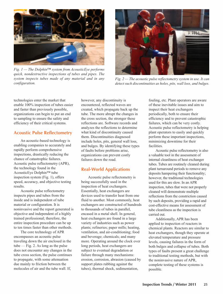
Comprehensive inspection and maintenance ofpipes and tubes are critical to keeping modernmanufacturing facilities working at top capacity.
Amir Feature IT Jan 2011:Layout 1 12/22/10 2:04 PM Page 24
Inspection Trends / Winter 2011 25
technologies enter the market that
enable 100% inspection of tubes easier
and faster than previously possible,
organizations can begin to put an end
to sampling to ensure the safety and
efficiency of their critical systems.
Acoustic Pulse Reflectometry
An acoustic-based technology is
enabling companies to accurately and
rapidly perform comprehensive
inspections, drastically reducing the
chance of catastrophic failures.
Acoustic pulse reflectometry (APR),
the technology found in the
AcousticEye Dolphin™ tube
inspection system (Fig. 1), offers
speed, accuracy, and objective testing
results.
Acoustic pulse reflectometry
inspects pipes and tubes from the
inside and is independent of tube
material or configuration. It is
noninvasive and the report generated is
objective and independent of a highly
trained professional; therefore, the
entire inspection procedure can be up
to ten times faster than other methods.
The core technology of APR
encompasses an acoustic pulse
traveling down the air enclosed in the
tube — Fig. 2. As long as the pulse
does not encounter any changes in the
tube cross section, the pulse continues
to propagate, with some attenuation
due mainly to friction between the
molecules of air and the tube wall. If,
however, any discontinuity is
encountered, reflected waves are
created, which propagate back up the
tube. The more abrupt the changes in
the cross section, the stronger these
reflections are. Software records and
analyzes the reflections to determine
what kind of discontinuity caused
them. Discontinuities diagnosed
include holes, pits, general wall loss,
and bulges. By identifying these types
of faults before problems arise,
organizations can prevent costly
failures down the road.
Real-World Applications
Acoustic pulse reflectometry is
being successfully used in the
inspection of heat exchangers.
Essentially, heat exchangers are
devices used to transfer heat from one
fluid to another. Most commonly, heat
exchangers are constructed of hundreds
to thousands of tubes in parallel,
encased in a metal shell. In general,
heat exchangers are found in a large
variety of industries such as power
plants; refineries; paper mills; heating,
ventilation, and air-conditioning; food
and beverage; chemicals; and many
more. Operating around the clock over
long periods, heat exchangers are
subject to eventual degradation or
failure through many mechanisms:
erosion, corrosion, abrasion (caused by
support plates rubbing against the
tubes), thermal shock, sedimentation,
fouling, etc. Plant operators are aware
of these inevitable issues and aim to
inspect their heat exchangers
periodically, both to ensure their
efficiency and to prevent catastrophic
failures, which can be very costly.
Acoustic pulse reflectometry is helping
plant operators to easily and quickly
perform these important inspections,
minimizing downtime for their
facilities.
Acoustic pulse reflectometry is also
a valuable tool in the assessment of
internal cleanliness of heat exchanger
tubes. Tubes are routinely cleaned during
plant turnaround periods to remove any
deposits hampering their functionality;
however, the traditional technologies
used for this are slow. In an APR
inspection, tubes that were not properly
cleaned will demonstrate multiple
reflections from the constriction caused
by such deposits, providing a rapid and
cost-effective means for assessment of
tube cleanliness as the inspection is
carried out.
Additionally, APR has been
applied to inspection of reactors in
chemical plants. Reactors are similar to
heat exchangers, though they operate at
elevated temperature and pressure
levels, causing failures in the form of
both bulges and collapse of tubes. Both
types of faults present a great challenge
to traditional testing methods, but with
the noninvasive nature of APR,
complete testing of these systems is
possible.
Fig. 1 — The Dolphin™ system from AcousticEye performsquick, nondestructive inspections of tubes and pipes. Thesystem inspects tubes made of any material and in anyconfiguration.
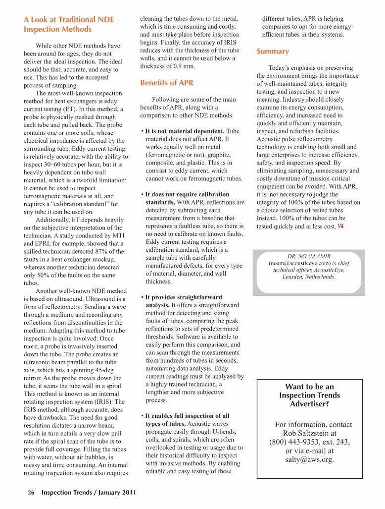
Fig. 2 — The acoustic pulse reflectometry system in use. It candetect such discontinuities as holes, pits, wall loss, and bulges.
Amir Feature IT Jan 2011:Layout 1 12/22/10 2:04 PM Page 25
Inspection Trends / January 201126
A Look at Traditional NDEInspection Methods
While other NDE methods have
been around for ages, they do not
deliver the ideal inspection. The ideal
should be fast, accurate, and easy to
use. This has led to the accepted
process of sampling.
The most well-known inspection
method for heat exchangers is eddy
current testing (ET). In this method, a
probe is physically pushed through
each tube and pulled back. The probe
contains one or more coils, whose
electrical impedance is affected by the
surrounding tube. Eddy current testing
is relatively accurate, with the ability to
inspect 30–60 tubes per hour, but it is
heavily dependent on tube wall
material, which is a twofold limitation:
It cannot be used to inspect
ferromagnetic materials at all, and
requires a “calibration standard” for
any tube it can be used on.
Additionally, ET depends heavily
on the subjective interpretation of the
technician. A study conducted by MTI
and EPRI, for example, showed that a
skilled technician detected 87% of the
faults in a heat exchanger mockup,
whereas another technician detected
only 50% of the faults on the same
tubes.
Another well-known NDE method
is based on ultrasound. Ultrasound is a
form of reflectometry: Sending a wave
through a medium, and recording any
reflections from discontinuities in the
medium. Adapting this method to tube
inspection is quite involved: Once
more, a probe is invasively inserted
down the tube. The probe creates an
ultrasonic beam parallel to the tube
axis, which hits a spinning 45-deg
mirror. As the probe moves down the
tube, it scans the tube wall in a spiral.
This method is known as an internal
rotating inspection system (IRIS). The
IRIS method, although accurate, does
have drawbacks. The need for good
resolution dictates a narrow beam,
which in turn entails a very slow pull
rate if the spiral scan of the tube is to
provide full coverage. Filling the tubes
with water, without air bubbles, is
messy and time consuming. An internal
rotating inspection system also requires
cleaning the tubes down to the metal,
which is time consuming and costly,
and must take place before inspection
begins. Finally, the accuracy of IRIS
reduces with the thickness of the tube
walls, and it cannot be used below a
thickness of 0.9 mm.
Benefits of APR
Following are some of the main
benefits of APR, along with a
comparison to other NDE methods.
• It is not material dependent. Tube
material does not affect APR. It
works equally well on metal
(ferromagnetic or not), graphite,
composite, and plastic. This is in
contrast to eddy current, which
cannot work on ferromagnetic tubes.
• It does not require calibration
standards. With APR, reflections are
detected by subtracting each
measurement from a baseline that
represents a faultless tube, so there is
no need to calibrate on known faults.
Eddy current testing requires a
calibration standard, which is a
sample tube with carefully
manufactured defects, for every type
of material, diameter, and wall
thickness.
• It provides straightforward
analysis. It offers a straightforward
method for detecting and sizing
faults of tubes, comparing the peak
reflections to sets of predetermined
thresholds. Software is available to
easily perform this comparison, and
can scan through the measurements
from hundreds of tubes in seconds,
automating data analysis. Eddy
current readings must be analyzed by
a highly trained technician, a
lengthier and more subjective
process.
• It enables full inspection of all
types of tubes. Acoustic waves
propagate easily through U-bends,
coils, and spirals, which are often
overlooked in testing or usage due to
their historical difficulty to inspect
with invasive methods. By enabling
reliable and easy testing of these
different tubes, APR is helping
companies to opt for more energy-
efficient tubes in their systems.
Summary
Today’s emphasis on preserving
the environment brings the importance
of well-maintained tubes, integrity
testing, and inspection to a new
meaning. Industry should closely
examine its energy consumption,
efficiency, and increased need to
quickly and efficiently maintain,
inspect, and refurbish facilities.
Acoustic pulse reflectometry
technology is enabling both small and
large enterprises to increase efficiency,
safety, and inspection speed. By
eliminating sampling, unnecessary and
costly downtime of mission-critical
equipment can be avoided. With APR,
it is not necessary to judge the
integrity of 100% of the tubes based on
a choice selection of tested tubes.
Instead, 100% of the tubes can be
tested quickly and at less cost.
DR. NOAM AMIR([email protected]) is chief
technical officer, AcousticEye, Leusden, Netherlands.
Want to be an Inspection Trends
Advertiser?
For information, contactRob Saltzstein at
(800) 443-9353, ext. 243, or via e-mail [email protected].
Amir Feature IT Jan 2011:Layout 1 12/22/10 2:05 PM Page 26

Feature
Industrial plants require safe and
reliable operations, but corrosion is a
major problem for the owners of
industrial equipment, installations, and
plants, due to the presence of corrosive
chemicals and harsh operating and
environmental conditions. For
industries throughout the world,
corrosion costs billions of dollars.
Mitigation costs include corrosion
prevention and detection, as well as
repairing the results of corrosion.
Corrosion requires reliable methods
for efficient detection. If undetected for a
long time, corrosion can cause leaks and
component failures, which reduce the
performance and reliability of important
equipment. In extreme cases, corrosion
can lead to unexpected disruptions that
are often costly in terms of lost
production, the expense of repairs, lost
or contaminated products, environmental
damage, and potential harm to humans.
In many facilities, key equipment may
have been in service for decades and
have the potential to be compromised
even by relatively slow corrosion
mechanisms.
What Is Corrosion?
Corrosion in welds occurs despite
the proper material having been
selected, industry standards followed,
and welds deposited that possess
complete joint penetration and have the
proper shape and contour. Corrosion
occurs as a result of the material’s
exposure to harsh conditions, and this
may be external, internal, or both.
Corrosion is a chemical or
electrochemical reaction between a
material, usually a metal, and its
environment, which produces a
deterioration of the material and its
properties. Corrosion can be
widespread and relatively uniform or
localized, in the form of pitting and
cracking.
Considerable efforts are expended
to reduce the extent of corrosion by
techniques such as inhibitors, coatings,
metallurgy selection, and cathodic
protection. However, these methods are
typically slow, and fail to completely
prevent corrosion.
It is, therefore, essential to
continuously monitor critical
equipment to prevent catastrophic
failure and to maintain excellent on-
stream factors.
How Can We DetectCorrosion?
Usually, corrosion detection is
performed with a thickness gauge or a
portable flaw detector. The residual
thickness is checked by spot
measurements or a couple of coarse
scans. If only general corrosion is
present, this method works fine.
However, this technique has a high
chance of missing localized pitting
corrosion, even when large surface
samples are scanned.
Ultrasonic Phased Array
Ultrasonic phased array
technology has become an established
method for advanced nondestructive
examination (NDE) applications.
Phased array technology reveals
defects hidden inside a structure or
weld by testing the structural integrity.
This newer ultrasonic testing technique
is based on generating and receiving
ultrasounds, but instead of a single
transducer and beam, phased array
equipment uses multiple ultrasonic
elements and electronic time delays to
create beams with constructive and
destructive interference patterns —
Fig. 1.
Phased array is an advanced pulse-
echo technique that utilizes multiple
miniaturized transducers and time
delays to shape the ultrasonic beam to
a desired angle and focus. The
versatility of the system permits
simultaneous views of different
presentations, such as sectoral views as
Ultrasonic Phased Arrays Quickly DetectCorrosionThe technology can be used on most common geometries, such as pipes, vessels, and tankbottoms suspected of having corrosion problems
Fig. 1 — The latest phased arrayequipment, such as the Phasor CV/DMfrom GE Sensing & InspectionTechnologies, uses multiple ultrasonicelements and electronic time delays.Advantages include repeatability, speedof inspection, and capability forinspecting complex geometries. Shownis the screen shot of the reference block.
Inspection Trends / Winter 2011 27
SGS Phased Array Feature Jan 2011 IT:Layout 1 12/22/10 3:46 PM Page 27
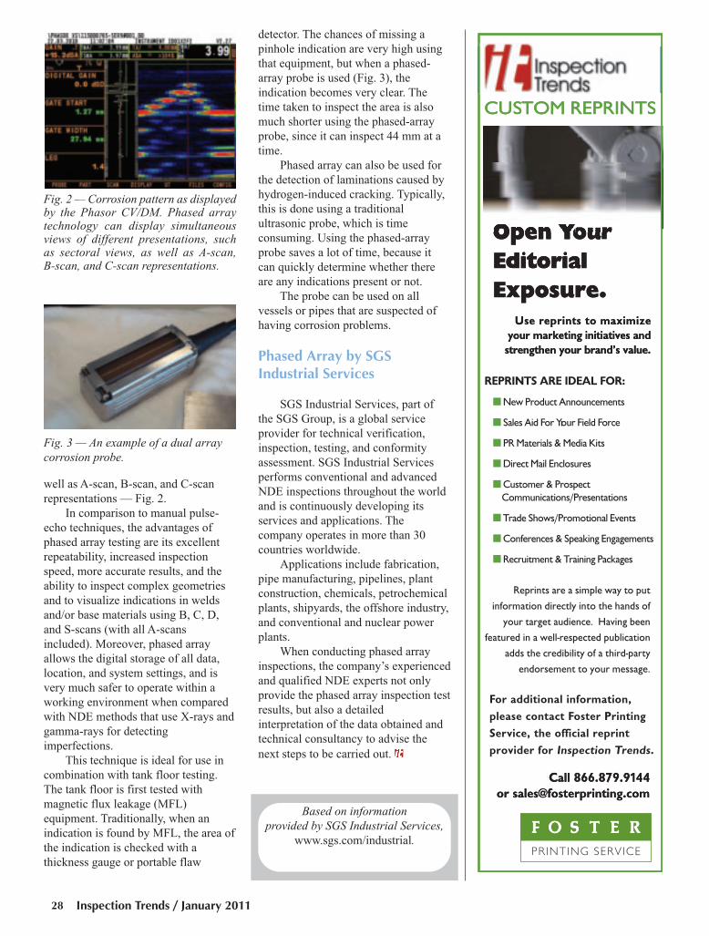
well as A-scan, B-scan, and C-scan
representations — Fig. 2.
In comparison to manual pulse-
echo techniques, the advantages of
phased array testing are its excellent
repeatability, increased inspection
speed, more accurate results, and the
ability to inspect complex geometries
and to visualize indications in welds
and/or base materials using B, C, D,
and S-scans (with all A-scans
included). Moreover, phased array
allows the digital storage of all data,
location, and system settings, and is
very much safer to operate within a
working environment when compared
with NDE methods that use X-rays and
gamma-rays for detecting
imperfections.
This technique is ideal for use in
combination with tank floor testing.
The tank floor is first tested with
magnetic flux leakage (MFL)
equipment. Traditionally, when an
indication is found by MFL, the area of
the indication is checked with a
thickness gauge or portable flaw
detector. The chances of missing a
pinhole indication are very high using
that equipment, but when a phased-
array probe is used (Fig. 3), the
indication becomes very clear. The
time taken to inspect the area is also
much shorter using the phased-array
probe, since it can inspect 44 mm at a
time.
Phased array can also be used for
the detection of laminations caused by
hydrogen-induced cracking. Typically,
this is done using a traditional
ultrasonic probe, which is time
consuming. Using the phased-array
probe saves a lot of time, because it
can quickly determine whether there
are any indications present or not.
The probe can be used on all
vessels or pipes that are suspected of
having corrosion problems.
Phased Array by SGSIndustrial Services
SGS Industrial Services, part of
the SGS Group, is a global service
provider for technical verification,
inspection, testing, and conformity
assessment. SGS Industrial Services
performs conventional and advanced
NDE inspections throughout the world
and is continuously developing its
services and applications. The
company operates in more than 30
countries worldwide.
Applications include fabrication,
pipe manufacturing, pipelines, plant
construction, chemicals, petrochemical
plants, shipyards, the offshore industry,
and conventional and nuclear power
plants.
When conducting phased array
inspections, the company’s experienced
and qualified NDE experts not only
provide the phased array inspection test
results, but also a detailed
interpretation of the data obtained and
technical consultancy to advise the
next steps to be carried out.
Fig. 3 — An example of a dual arraycorrosion probe.
Based on informationprovided by SGS Industrial Services,
www.sgs.com/industrial.
Fig. 2 — Corrosion pattern as displayedby the Phasor CV/DM. Phased arraytechnology can display simultaneousviews of different presentations, such as sectoral views, as well as A-scan, B-scan, and C-scan representations.
T R E N D S
Inspection Trends / January 201128
SGS Phased Array Feature Jan 2011 IT:Layout 1 12/22/10 3:46 PM Page 28
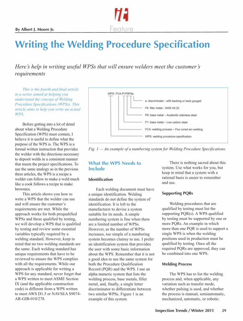
FeatureBy Albert J. Moore Jr.
This is the fourth and final articlein a series aimed at helping youunderstand the concept of WeldingProcedure Specifications (WPSs). Thisarticle aims to help you write an actualWPS.
Before getting into a lot of detail
about what a Welding Procedure
Specification (WPS) must contain, I
believe it is useful to define what the
purpose of the WPS is. The WPS is a
formal written instruction that provides
the welder with the directions necessary
to deposit welds in a consistent manner
that meets the project specifications. To
use the same analogy as in the previous
three articles, the WPS is a recipe a
welder can follow to make a weld much
like a cook follows a recipe to make
brownies.
This article shows you how to
write a WPS that the welder can use
and will ensure the customer’s
requirements are met. While the
approach works for both prequalified
WPSs and those qualified by testing,
we will develop a WPS that is qualified
by testing and review some essential
variables typically required by a
welding standard. However, keep in
mind that no two welding standards are
the same. Each welding standard has
unique requirements that have to be
reviewed to ensure the WPS complies
with all the requirements. While our
approach is applicable for writing a
WPS for any standard, never forget that
a WPS written to meet ASME Section
IX (and the applicable construction
code) is different from a WPS written
to meet AWS D1.5 or NAVSEA S9074-
AR-GIB-010/278.
What the WPS Needs toInclude
Identification
Each welding document must have
a unique identification. Welding
standards do not define the system of
identification. It is left to the
manufacturer to devise a system
suitable for its needs. A simple
numbering system is fine when there
are a limited number of WPSs.
However, as the number of WPSs
increases, too simple of a numbering
system becomes clumsy to use. I prefer
an identification system that provides
the user with some basic information
about the WPS. Remember that it is not
a good idea to use the same system for
both the Procedure Qualification
Record (PQR) and the WPS. I use an
alpha numeric system that lists the
welding process, base metals, filler
metal, and, finally, a single letter
discriminator to differentiate between
two similar WPSs. Figure 1 is an
example of this system.
There is nothing sacred about this
system. Use what works for you, but
keep in mind that a system with a
rational basis is easier to remember
and use.
Supporting PQRs
Welding procedures that are
qualified by testing must list the
supporting PQR(s). A WPS qualified
by testing must be supported by one or
more PQRs. An example in which
more than one PQR is used to support a
single WPS is when the welding
positions used in production must be
qualified by testing. Once all the
required PQRs are approved, they can
be combined into one WPS.
Welding Process
The WPS has to list the welding
process and, when applicable, any
variation such as transfer mode,
whether pulsing is used, and whether
the process is manual, semiautomatic,
mechanized, automatic, or robotic.
Inspection Trends / Winter 2011 29
Writing the Welding Procedure Specification
Here’s help in writing useful WPSs that will ensure welders meet the customer’srequirements
Fig. 1 — An example of a numbering system for Welding Procedure Specifications.
Moore WPS Feature IT Jan 2011:Layout 1 12/22/10 1:43 PM Page 29
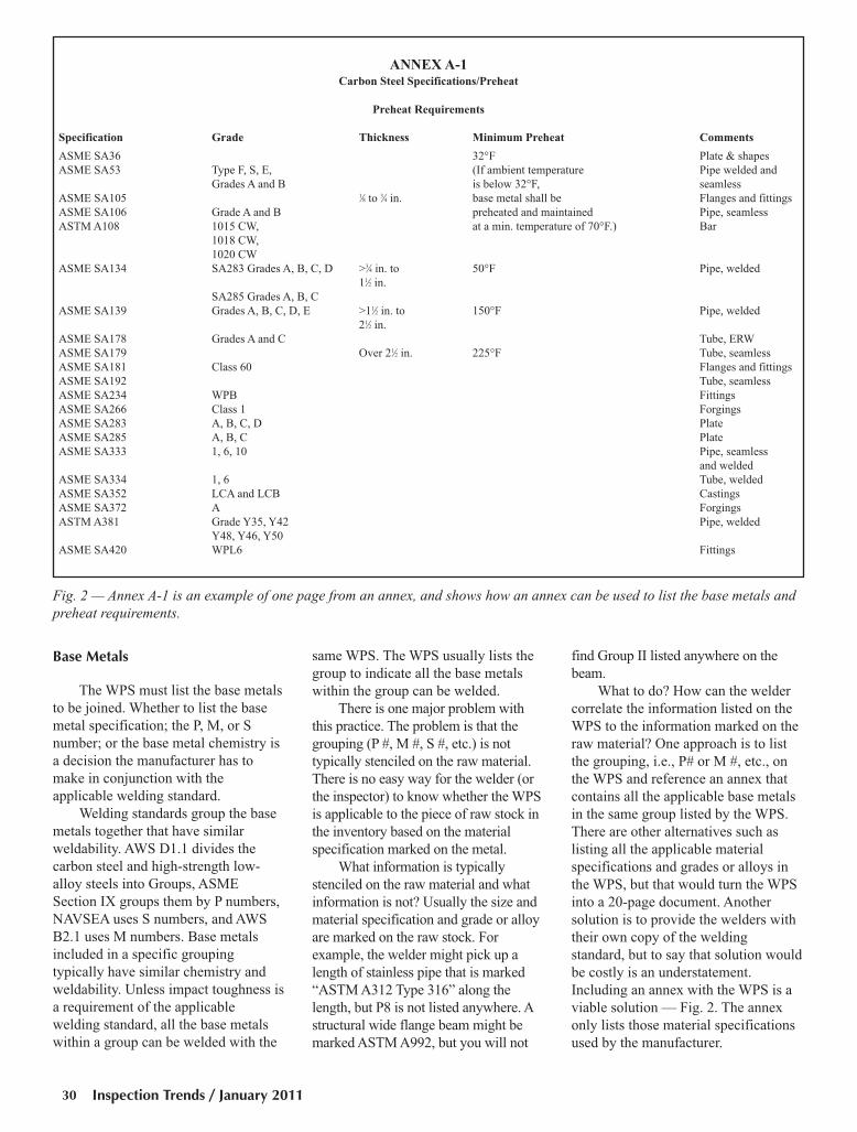
Inspection Trends / January 201130
ANNEX A-1Carbon Steel Specifications/Preheat
Preheat Requirements
Specification Grade Thickness Minimum Preheat Comments
ASME SA36 32°F Plate & shapes
ASME SA53 Type F, S, E, (If ambient temperature Pipe welded and
Grades A and B is below 32°F, seamless
ASME SA105 1⁄8 to 3⁄4 in. base metal shall be Flanges and fittings
ASME SA106 Grade A and B preheated and maintained Pipe, seamless
ASTM A108 1015 CW, at a min. temperature of 70°F.) Bar
1018 CW,
1020 CW
ASME SA134 SA283 Grades A, B, C, D >3⁄4 in. to 50°F Pipe, welded
11⁄2 in.
SA285 Grades A, B, C
ASME SA139 Grades A, B, C, D, E >11⁄2 in. to 150°F Pipe, welded
21⁄2 in.
ASME SA178 Grades A and C Tube, ERW
ASME SA179 Over 21⁄2 in. 225°F Tube, seamless
ASME SA181 Class 60 Flanges and fittings
ASME SA192 Tube, seamless
ASME SA234 WPB Fittings
ASME SA266 Class 1 Forgings
ASME SA283 A, B, C, D Plate
ASME SA285 A, B, C Plate
ASME SA333 1, 6, 10 Pipe, seamless
and welded
ASME SA334 1, 6 Tube, welded
ASME SA352 LCA and LCB Castings
ASME SA372 A Forgings
ASTM A381 Grade Y35, Y42 Pipe, welded
Y48, Y46, Y50
ASME SA420 WPL6 Fittings
Fig. 2 — Annex A-1 is an example of one page from an annex, and shows how an annex can be used to list the base metals andpreheat requirements.
Base Metals
The WPS must list the base metals
to be joined. Whether to list the base
metal specification; the P, M, or S
number; or the base metal chemistry is
a decision the manufacturer has to
make in conjunction with the
applicable welding standard.
Welding standards group the base
metals together that have similar
weldability. AWS D1.1 divides the
carbon steel and high-strength low-
alloy steels into Groups, ASME
Section IX groups them by P numbers,
NAVSEA uses S numbers, and AWS
B2.1 uses M numbers. Base metals
included in a specific grouping
typically have similar chemistry and
weldability. Unless impact toughness is
a requirement of the applicable
welding standard, all the base metals
within a group can be welded with the
same WPS. The WPS usually lists the
group to indicate all the base metals
within the group can be welded.
There is one major problem with
this practice. The problem is that the
grouping (P #, M #, S #, etc.) is not
typically stenciled on the raw material.
There is no easy way for the welder (or
the inspector) to know whether the WPS
is applicable to the piece of raw stock in
the inventory based on the material
specification marked on the metal.
What information is typically
stenciled on the raw material and what
information is not? Usually the size and
material specification and grade or alloy
are marked on the raw stock. For
example, the welder might pick up a
length of stainless pipe that is marked
“ASTM A312 Type 316” along the
length, but P8 is not listed anywhere. A
structural wide flange beam might be
marked ASTM A992, but you will not
find Group II listed anywhere on the
beam.
What to do? How can the welder
correlate the information listed on the
WPS to the information marked on the
raw material? One approach is to list
the grouping, i.e., P# or M #, etc., on
the WPS and reference an annex that
contains all the applicable base metals
in the same group listed by the WPS.
There are other alternatives such as
listing all the applicable material
specifications and grades or alloys in
the WPS, but that would turn the WPS
into a 20-page document. Another
solution is to provide the welders with
their own copy of the welding
standard, but to say that solution would
be costly is an understatement.
Including an annex with the WPS is a
viable solution — Fig. 2. The annex
only lists those material specifications
used by the manufacturer.
Moore WPS Feature IT Jan 2011:Layout 1 12/27/10 2:29 PM Page 30
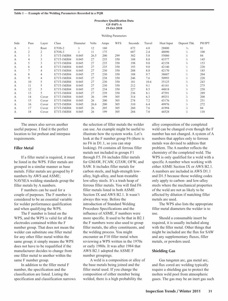
The annex also serves another
useful purpose. I find it the perfect
location to list preheat and interpass
requirements.
Filler Metal
If a filler metal is required, it must
be listed in the WPS. Filler metals are
grouped in a similar manner as base
metals. Filler metals are grouped by F
numbers by AWS and ASME;
NAVSEA welding standards group the
filler metals by A numbers.
F numbers can be used for a
couple of purposes. The F number is
considered to be an essential variable
for welder performance qualification
and when qualifying the WPS.
The F number is listed on the
WPS, and the WPS is valid for all the
electrodes contained within the F
number group. That does not mean the
welder can substitute one filler metal
for any other filler metal within the
same group; it simply means the WPS
does not have to be requalified if the
manufacturer decides to change from
one filler metal to another within the
same F number group.
In addition to the filler metal F
number, the specification and the
classification are listed. Listing the
specification and classification narrows
the selection of filler metals the welder
can use. An example might be useful to
illustrate how the system works. Let’s
look at the F number group F6 (there is
no F6 in D1.1, so you can stop
looking). F6 contains all ferrous filler
metals not included in groups F1
through F5. F6 includes filler metals
for GMAW, FCAW, GTAW, OFW, and
SAW. It includes filler metals for
carbon steels, and high-strength low-
alloy, high-alloy, and heat-treatable
low-alloy steels. It’s a trash heap of
ferrous filler metals. You will find F6
filler metals listed in both ASME
Section IX and AWS B2.1. It wasn’t
always this way. Before the
introduction of Standard Welding
Procedure Specifications and the
influence of ASME, F numbers were
more specific. It used to be that in B2.1
the F numbers were also used to group
filler metals, the alloy constituents, and
the welding process. You might
encounter an F10 filler metal when
reviewing a WPS written in the 1970s
or early 1980s. It was after 1984 that
AWS B2.1 adopted the ASME F
number groupings.
A weld is a composition or alloy of
the base metals being joined and the
filler metal used. If you change the
composition of either member being
welded, there is a high probability the
alloy composition of the completed
weld can be changed even though the F
number has not changed. A system of A
numbers that applies only to ferrous
metals was devised to address that
problem. The A number reflects the
chemistry of the completed weld. The
WPS is only qualified for a weld with a
specific A number when working with
either ASME Section IX or AWS B2.1.
A numbers are included in AWS D1.1
and D1.5 because those welding codes
only apply to carbon- and low-alloy
steels where the mechanical properties
of the weld are not as likely to be
affected by dilution if matching filler
metals are used.
The WPS also lists the appropriate
filler metal diameters the welder is to
use.
Should a consumable insert be
required, it is usually included along
with the filler metal. Other things that
might be included are the flux for SAW
and any supplementary fluxes, filler
metals, or powders used.
Shielding Gas
Gas tungsten arc, gas metal arc,
and flux cored arc welding typically
require a shielding gas to protect the
molten weld pool from atmospheric
gases. The gas may be an inert gas such
Inspection Trends / Winter 2011 31
Table 1 — Example of the Welding Parameters Recorded in a PQR
Procedure Qualification Data
GF-F6P1-A
19-Oct-2010
Welding Parameters
Side Pass Layer Class Diameter Volts Amps WFS Seconds Travel Heat Input Deposit Thk. PH/IPT
A 1 Root E7OS-2 1⁄8 12 160 672 4.0 28800 3⁄16 81
A 2 2 E7OS-3 1⁄8 11 175 687 2.4 48090 1⁄4 108
A 3 3 E71T-1MJH4 0.045 26.5 200 299 302 5.8 55080 3⁄8 84
A 4 3 E71T-1MJH4 0.045 27 235 350 188 8.8 43377 3⁄8 145
A 5 3 E71T-1MJH4 0.045 27 235 350 198 9.0 42158 3⁄8 153
A 6 4 E71T-1MJH4 0.045 27 235 350 193 9.0 42140 1⁄2 220
A 7 4 E71T-1MJH4 0.045 27 230 350 208 8.8 42170 1⁄2 185
A 8 4 E71T-1MJH4 0.045 27 230 350 188 9.7 38607 1⁄2 204
A 9 4 E71T-1MJH4 0.045 27 238 350 246 7.6 50993 1⁄2 220
A 10 5 E71T-1MJH4 0.045 27 230 350 181 10.6 35125 3⁄4 243
A 11 5 E71T-1MJH4 0.045 27 230 350 212 9.1 41141 3⁄4 275
A 12 5 E71T-1MJH4 0.045 27 234 350 227 8.5 44818 3⁄4 258
A 13 5 E71T-1MJH4 0.045 27 239 350 236 8.1 47591 3⁄4 289
A 14 Cover E71T-1MJH4 0.045 26 199 305 314 6.3 49251 7⁄8 208
A 15 Cover E71T-1MJH4 0.045 26 200 305 274 7.2 43176 7⁄8 251
A 16 Cover E71T-1MJH4 0.045 26.6 200 305 310 6.4 49976 7⁄8 272
A 17 Cover E71T-1MJH4 0.045 26 205 305 260 7.6 41994 7⁄8 84
A 18 Cover E71T-1MJH4 0.045 26 199 305 284 7.0 44528 7⁄8 110
Moore WPS Feature IT Jan 2011:Layout 1 12/27/10 2:30 PM Page 31

as argon or helium, a reactive gas such
as carbon dioxide, or a combination of
gases that may have minor additions of
oxygen or hydrogen. The gas or gas
mix to be used is influenced by the
welding process, the base metals being
joined, and, possibly, the welding
position.
AWS first published A5.32,
Specification for Welding ShieldingGases, in 1997. Shielding gases meeting
the requirements of A5.32 are pure
enough for all welding applications
except for the gases used for laser beam
welding.
In addition to listing the shielding
gas, the WPS needs to list the
appropriate flow rates. The flow rate is
a function of the shielding gas and the
diameter of the gas nozzle used.
Different shielding gases have different
densities, which necessitates using the
proper flow meter and flow rate to
provide adequate shielding of the
molten weld pool. The shielding gas is
usually an essential variable. The WPS
will have to be requalified if the
manufacturer decides to change to a
different shielding gas or mixture of
shielding gases.
Trailing gases and purge gases are
also listed when they are required. The
need to use a purge gas and the type of
purge gas required is not left to the
discretion of the welder.
While on the subject of purge
gases, it is my recommendation that a
method of determining when the purge
is satisfactory should be included in the
WPS. Different base metals can tolerate
different levels of contamination.
Reactive base metals are intolerant of
moisture, oxygen, or nitrogen when
compared to austenitic stainless steel.
Success or failure when welding
reactive and refractory base metals can
depend on the completeness of the
purging operation. Specific instructions
for detailed information about purging
can be provided to the welder through
use of another annex. The WPS can
simply list that purging is required and
reference the appropriate annex for
more detailed information.
Welding Parameters
The WPS has to provide the
information the welder needs to set the
welding parameters. The information
the welder needs includes the type of
welding machine suitable for the
welding process to be used, current
type, polarity, arc voltage, amperage
(wire feed speed), electrode extension
(if applicable), tungsten type and end
preparation (if applicable), travel
speed, etc. The parameters listed in the
WPS are those that are appropriate for
the welding process being used.
The WPS is based on the
information gathered while welding the
successful PQR. If the PQR was
properly documented, it will list the
welding parameters the welder used
while welding the test coupon. The
parameters listed in the PQR serve as
the starting point for the WPS. The
welding parameters used to weld the
test coupon are “good” because the
test weldments passed all the required
tests. The welding parameters used
when the test weldments were welded
are likely to vary somewhat from bead
to bead. An example of the welding
parameters recorded in the PQR are
listed in Table 1.
Recording the welding parameters
in a MicroSoft Excel™ spreadsheet
makes it easy to determine the
minimum, maximum, and ranges for
each parameter used to weld the test
coupon. The descriptive statistical tool
provided by MicroSoft Excel™ can be
used to analyze the data. The
presentation is shown in Table 2.
Some welding standards such as
AWS D1.1, D1.5, B2.1, etc. allow the
ranges listed on the WPS to be “opened
up” by certain amounts, usually
expressed as percentages of the values
recorded on the PQR. In such a case, I
would typically use the median value
shown in Table 2 as my data point.
It is acceptable to use the
parameter ranges listed by the
manufacturer if the welding standard
used does not impose limits on those
ranges, i.e., voltage, wire feed speed
(WFS), amperages, etc. The ranges
listed by the WPS should be
reasonable. The average welder should
be able to deposit an acceptable weld
using the high and low values of the
ranges listed in the WPS.
There are three important welding
parameters to note when welding with
either FCAW or GMAW. They are
important because they are “constants”
that the welder sets. The parameters are
arc voltage, wire feed speed, and
electrode extension (EE). In general,
once the wire feed speed is dialed into
the wire feeder, it does not change
whether the welder is actually welding
or holding the gun in the air. Amperage
will vary as the welder increases or
decreases the electrode extension.
Welders can use the electrode
extension to their advantage to increase
the amperage by shortening the EE
slightly or decrease the amperage by
Inspection Trends / January 201132
Table 2 — Descriptive Statistics. Analysis of the Welding Data Recorded in the PQR
Data Analysis
Procedure Qualification
GF-F6P1-A
19-Oct-2010
Volts Amps WFS Seconds Travel HI PH/IPT
Mean 26.7 221.2 332.8 238.8 8.1 44507.9 200.1
Median 27.0 230.0 350.0 231.5 8.3 43276.2 214.0
Standard Deviation 0.4 16.8 23.0 46.6 1.3 5006.5 67.3
Range 1.0 40.0 51.0 133.0 4.8 19954.3 205.0
Minimum 26.0 199.0 299.0 181.0 5.8 35125.3 84.0
Maximum 27.0 239.0 350.0 314.0 10.6 55079.7 289.0
Moore WPS Feature IT Jan 2011:Layout 1 12/27/10 2:30 PM Page 32
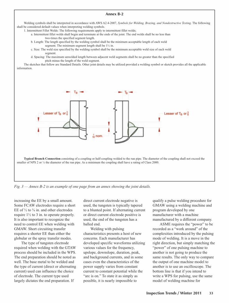
increasing the EE by a small amount.
Some FCAW electrodes require a short
EE of ½ to ¾ in. and other electrodes
require 1½ to 3 in. to operate properly.
It is also important to recognize the
need to control EE when welding with
GMAW. Short circuiting transfer
requires a shorter EE than either the
globular or the spray transfer modes.
The type of tungsten electrode
required when welding with the GTAW
process should be included in the WPS.
The end preparation should be noted as
well. The base metal to be welded and
the type of current (direct or alternating
current) used can influence the choice
of electrode. The current type used
largely dictates the end preparation. If
direct current electrode negative is
used, the tungsten is typically tapered
to a blunted point. If alternating current
or direct current electrode positive is
used, the end of the tungsten has a
balled end.
Welding with pulsing
characteristics presents a host of new
concerns. Each manufacturer has
developed specific waveforms utilizing
various values for the frequency,
upslope, downslope, duration, peak,
and background currents, and in some
cases even the characteristics of the
power supply varies from constant
current to constant potential while the
“arc is on.” To state it as simply as
possible, it is nearly impossible to
qualify a pulse welding procedure for
GMAW using a welding machine and
program developed by one
manufacturer with a machine
manufactured by a different company.
ASME requires the “power” to be
recorded as a “work around” of the
complexities introduced by the pulsing
mode of welding. It is a move in the
right direction, but simply matching the
“power” of one pulsing machine to
another is not going to produce the
same results. The only way to compare
the output of one machine model to
another is to use an oscilloscope. The
bottom line is that if you intend to
write a WPS for pulsing, use the same
model of welding machine for
Inspection Trends / Winter 2011 33
Annex B-2
Welding symbols shall be interpreted in accordance with AWS A2.4-2007, Symbols for Welding, Brazing, and Nondestructive Testing. The following
shall be considered default values when interpreting welding symbols.
1. Intermittent Fillet Welds: The following requirements apply to intermittent fillet welds;
a. Intermittent fillet welds shall begin and terminate at the ends of the joint. The end welds shall be no less than
two-times the specified segment length.
b. Length: The length specified by the welding symbol shall be the minimum acceptable length of each weld
segment. The minimum segment length shall be 1½ in.
c. Size: The weld size specified by the welding symbol shall be the minimum acceptable weld size of each weld
segment.
d. Spacing: The maximum unwelded length between adjacent weld segments shall be no greater than the specified
pitch minus the length of the weld segment.
The sketches that follow are Standard Details. Other joint details may be utilized provided a welding symbol or sketch provides all the applicable
information.
Typical Branch Connection consisting of a coupling or half-coupling welded to the run pipe. The diameter of the coupling shall not exceed the
smaller of NPS 2 or ¼ the diameter of the run pipe. As a minimum the coupling shall have a rating of Class 2000.
Fig. 3 — Annex B-2 is an example of one page from an annex showing the joint details.
Moore WPS Feature IT Jan 2011:Layout 1 12/27/10 2:31 PM Page 33
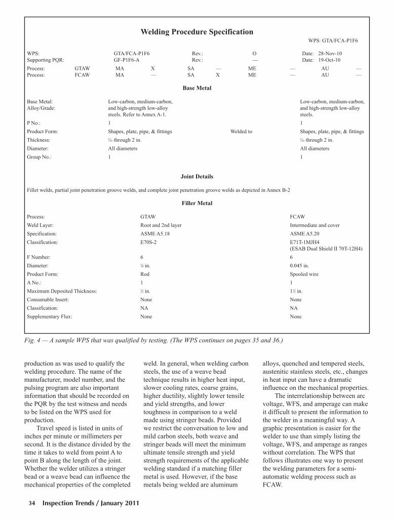
production as was used to qualify the
welding procedure. The name of the
manufacturer, model number, and the
pulsing program are also important
information that should be recorded on
the PQR by the test witness and needs
to be listed on the WPS used for
production.
Travel speed is listed in units of
inches per minute or millimeters per
second. It is the distance divided by the
time it takes to weld from point A to
point B along the length of the joint.
Whether the welder utilizes a stringer
bead or a weave bead can influence the
mechanical properties of the completed
weld. In general, when welding carbon
steels, the use of a weave bead
technique results in higher heat input,
slower cooling rates, coarse grains,
higher ductility, slightly lower tensile
and yield strengths, and lower
toughness in comparison to a weld
made using stringer beads. Provided
we restrict the conversation to low and
mild carbon steels, both weave and
stringer beads will meet the minimum
ultimate tensile strength and yield
strength requirements of the applicable
welding standard if a matching filler
metal is used. However, if the base
metals being welded are aluminum
alloys, quenched and tempered steels,
austenitic stainless steels, etc., changes
in heat input can have a dramatic
influence on the mechanical properties.
The interrelationship between arc
voltage, WFS, and amperage can make
it difficult to present the information to
the welder in a meaningful way. A
graphic presentation is easier for the
welder to use than simply listing the
voltage, WFS, and amperage as ranges
without correlation. The WPS that
follows illustrates one way to present
the welding parameters for a semi-
automatic welding process such as
FCAW.
Inspection Trends / January 201134
Welding Procedure SpecificationWPS: GTA/FCA-P1F6
WPS: GTA/FCA-P1F6 Rev.: O Date: 28-Nov-10
Supporting PQR: GF-P1F6-A Rev.: — Date: 19-Oct-10
Process: GTAW MA X SA — ME — AU —
Process: FCAW MA — SA X ME — AU —
Base Metal
Base Metal: Low-carbon, medium-carbon, Low-carbon, medium-carbon,
Alloy/Grade: and high-strength low-alloy and high-strength low-alloy
steels. Refer to Annex A-1. steels.
P No.: 1 1
Product Form: Shapes, plate, pipe, & fittings Welded to Shapes, plate, pipe, & fittings
Thickness: 1⁄16 through 2 in. 1⁄16 through 2 in.
Diameter: All diameters All diameters
Group No.: 1 1
Joint Details
Fillet welds, partial joint penetration groove welds, and complete joint penetration groove welds as depicted in Annex B-2
Filler Metal
Process: GTAW FCAW
Weld Layer: Root and 2nd layer Intermediate and cover
Specification: ASME A5.18 ASME A5.20
Classification: E70S-2 E71T-1MJH4
(ESAB Dual Shield II 70T-12H4)
F Number: 6 6
Diameter: 1⁄8 in. 0.045 in.
Product Form: Rod Spooled wire
A No.: 1 1
Maximum Deposited Thickness: 1⁄2 in. 11⁄2 in.
Consumable Insert: None None
Classification: NA NA
Supplementary Flux: None None
Fig. 4 — A sample WPS that was qualified by testing. (The WPS continues on pages 35 and 36.)
Moore WPS Feature IT Jan 2011:Layout 1 12/22/10 1:46 PM Page 34
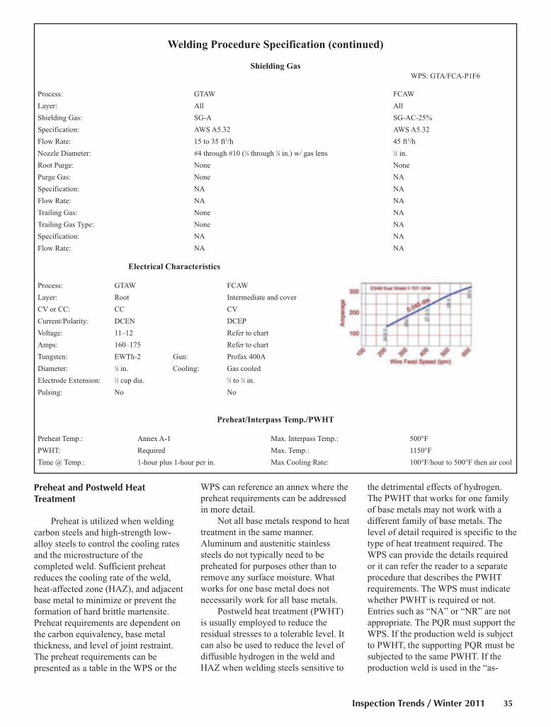
Preheat and Postweld Heat Treatment
Preheat is utilized when welding
carbon steels and high-strength low-
alloy steels to control the cooling rates
and the microstructure of the
completed weld. Sufficient preheat
reduces the cooling rate of the weld,
heat-affected zone (HAZ), and adjacent
base metal to minimize or prevent the
formation of hard brittle martensite.
Preheat requirements are dependent on
the carbon equivalency, base metal
thickness, and level of joint restraint.
The preheat requirements can be
presented as a table in the WPS or the
WPS can reference an annex where the
preheat requirements can be addressed
in more detail.
Not all base metals respond to heat
treatment in the same manner.
Aluminum and austenitic stainless
steels do not typically need to be
preheated for purposes other than to
remove any surface moisture. What
works for one base metal does not
necessarily work for all base metals.
Postweld heat treatment (PWHT)
is usually employed to reduce the
residual stresses to a tolerable level. It
can also be used to reduce the level of
diffusible hydrogen in the weld and
HAZ when welding steels sensitive to
the detrimental effects of hydrogen.
The PWHT that works for one family
of base metals may not work with a
different family of base metals. The
level of detail required is specific to the
type of heat treatment required. The
WPS can provide the details required
or it can refer the reader to a separate
procedure that describes the PWHT
requirements. The WPS must indicate
whether PWHT is required or not.
Entries such as “NA” or “NR” are not
appropriate. The PQR must support the
WPS. If the production weld is subject
to PWHT, the supporting PQR must be
subjected to the same PWHT. If the
production weld is used in the “as-
Inspection Trends / Winter 2011 35
Welding Procedure Specification (continued)
Shielding Gas
WPS: GTA/FCA-P1F6
Process: GTAW FCAW
Layer: All All
Shielding Gas: SG-A SG-AC-25%
Specification: AWS A5.32 AWS A5.32
Flow Rate: 15 to 35 ft3/h 45 ft3/h
Nozzle Diameter: #4 through #10 (1⁄4 through 5⁄8 in.) w/ gas lens 1⁄2 in.
Root Purge: None None
Purge Gas: None NA
Specification: NA NA
Flow Rate: NA NA
Trailing Gas: None NA
Trailing Gas Type: None NA
Specification: NA NA
Flow Rate: NA NA
Electrical Characteristics
Process: GTAW FCAW
Layer: Root Intermediate and cover
CV or CC: CC CV
Current/Polarity: DCEN DCEP
Voltage: 11–12 Refer to chart
Amps: 160–175 Refer to chart
Tungsten: EWTh-2 Gun: Profax 400A
Diameter: 1⁄8 in. Cooling: Gas cooled
Electrode Extension: 1⁄2 cup dia. 1⁄2 to 3⁄4 in.
Pulsing: No No
Preheat/Interpass Temp./PWHT
Preheat Temp.: Annex A-1 Max. Interpass Temp.: 500°F
PWHT: Required Max. Temp.: 1150°F
Time @ Temp.: 1-hour plus 1-hour per in. Max Cooling Rate: 100°F/hour to 500°F then air cool
Moore WPS Feature IT Jan 2011:Layout 1 12/22/10 1:47 PM Page 35

Inspection Trends / January 201136
welded” condition, the PQR must be
tested in the as-welded condition.
Technique
There are several welding
variables that are listed under the
heading “technique.” Whether weave
beads or stringer beads are used can be
presented here. Any limitations on the
width of the weave bead can be listed
under this heading.
This is a good time to note that
welding standards published by ASME1,
AWS, and even the military do not place
limits on the width of a weld bead
deposited with the SMAW process. Any
such restriction on the width of a weave
bead is imposed by the manufacturer and
not the code. When notch toughness is
required, the width of the bead is
controlled to limit the heat input by
controlling the travel speed.
Other information listed under the
heading of “technique” include travel
speed, whether single-pass or multipass
welds are used, the need for and
method of backgouging, cleaning, and
welding positions. Technique is a
catch-all category for any information
not listed elsewhere in the WPS.
Joint Details
A WPS can address the
requirements applicable to a single
joint detail or many joint details. A
WPS can easily accommodate the
details for one or two joints, but a
general WPS that covers many
different joints can easily grow in size
to the point where it weighs more than
the components being welded. Once
again, the annex comes to the rescue. A
separate annex can list all the
appropriate joint details, fit-up
requirements, and tolerances applicable
to the work — Fig. 3. The WPS can
refer the reader to the appropriate
annex used to show the details of each
joint. When an annex is used, each
joint detail should be assigned a unique
identifier. There are a couple of
systems in place already. Two that
come to mind are the joint designations
found in AWS D1.X and MIL-STD-
22D. There is no need to reinvent a
system when it is easier to adopt
something that already exists.
Acceptance Criteria
Welding standards typically do not
include a requirement for the WPS to
list the applicable visual acceptance
criteria for the weld. However, the
WPS and the drawings are the two
primary documents the welder works
with. What better vehicle is available to
define what visual acceptance criteria
is appropriate for a particular job?
Welding Procedure Specification (continued)
Technique
WPS: GTA/FCA-P1F6
Process: GTAW FCAW
Layer: Root and second layer when CJP Intermediate and cover layers for
from one side without backing is specified. all fillet welds, PJP, and CJP welds
made with backing.
Position: All All
Progression: Vertical Uphill Vertical Uphill
Travel Speed: 2–5 in./min 4–12 in./min
Stringer/Weave: Either, split layer required when Either, split layer required when
previous layer exceeds 3⁄8 in. in width. previous layer exceeds 5⁄8 in. in width.
Single/Multiple Electrode: Single Single
Electrode Spacing: NA NA
Single/Multiple Pass per Side Either Either
Peening: None None
Chamber: None None
Method of Cleaning: Refer to Annex B Refer to Annex B
Method of Back Gouge: Refer to Annex B Refer to Annex B
Heat Input Limitations: 60 kJ/in. 60 kJ/in.
Other:
FCAW electrodes shall be stored in the manufacturer’s sealed container until needed. Once opened, the spool of electrode shall be used within an 8-hour pe-
riod, electrode not used shall be discarded or any electrode not exposed for the full 8-hours may be returned to a vented electrode holding oven set to 250° F
minimum.
This example of a WPS is for illustrative purposes only. It is not intended to meet the specific requirements of any welding standard and is not intended for
production welding.
ASME SA285 A, B, C Plate
ASME SA333 1, 6, 10 Pipe, seamless and welded
ASME SA334 1, 6 Tube, welded
ASME SA352 LCA and LCB Castings
ASME SA372 A Forgings
1. ASME does have a restriction on thebead width when a repair is made andPWHT is not used.
Moore WPS Feature IT Jan 2011:Layout 1 12/22/10 1:48 PM Page 36

The WPS can be the vehicle used
to link the welding requirements and
the visual acceptance criteria. It can
reference a specific annex where the
visual acceptance criteria are listed.
I hear your wheels turning already:
It is not required by the code, the
welder should already know the
acceptance criteria, every weld should
be a perfect weld, etc., so why should it
be included in the WPS? Well, welcome
to the real world. The visual acceptance
criteria can change from one job to
another. Welders should be made aware
of any special requirements and of the
visual acceptance criteria that apply to
each job.
Welders are responsible for the
work they produce. They should be
responsible for examining the
completed weld before it is passed on
to quality control for the final
inspection. If the welders are to be an
integral part of the quality control
process, they must know what visual
acceptance criteria are applicable. The
annex listing the applicable acceptance
criteria and special requirements is a
means of providing welders with the
information they need to do the job
properly.
Format
The WPS and the PQR are not
required to be presented in any
particular format. ASME, AWS, API,
etc., provide sample forms that can be
used as templates for typical PQRs or
WPSs, but their use is not mandatory.
You may decide to develop a format
that allows you to increase the size of
the font so the welder can read it in
dim light or the sample forms may not
provide ample space for additional
information you believe will be useful
to the welder.
An Example of a WPS
The example shown in Fig. 4 is a
WPS that uses two different welding
processes. The WPS is qualified by
testing, i.e., it is supported by a single
PQR where the test plate was welded
using the two processes listed in by the
WPS. The welding parameters
recorded on the PQR are listed in
Table 1. The format I use is similar to
one you may have seen before, but I
have tweaked it to suit my needs. I
believe the guidelines I have presented
here will help prepare you to write
your own WPSs.
Inspection Trends / Winter 2011 37
ALBERT J. MOORE JR.([email protected]) is vice
president, Marion Testing &Inspection, Canton, Conn. He is an
AWS Senior Certified WeldingInspector and an ASNT ACCP NDTLevel III. He is also a member of theAWS Certification Committee and theCommittee on Methods of Inspection
of Welds.
Moore WPS Feature IT Jan 2011:Layout 1 12/22/10 1:48 PM Page 37

ASNT 20th Annual Research Symposium and Spring
Conference. March 21–25, Hyatt Regency San Francisco,
San Francisco, Calif. Contact American Society for
Nondestructive Testing, (800) 222-2768 or www.asnt.org.
Houstex. April 18–20, George R. Brown Convention Center,
Houston, Tex. Contact Society of Manufacturing Engineers,
www.houstexonline.com.
AWS Weldmex. May 11–13, Cintermex, Monterrey, Mexico.
Held in conjunction with FABTECH Mexico and Metalform
Mexico. Contact American Welding Society (800/305) 443-
9353 or www.awsweldmex.com.
International Symposium on Nondestructive Testing of
Materials and Structures. May 15–18, Suleyman Demirel
Cultural Center, Maslak Campus of Istanbul Technical
University (ITU), Istanbul, Turkey. Hosted by Istanbul
Technical University. Contact Symposium Secretariat at
90.212.285.3756, or www.ndtms.itu.edu.tr.
ASNT Fall Conf. and Quality Testing Show. Oct. 24–28,
Palm Springs Convention Center, Palm Springs, Calif.
Contact American Society for Nondestructive Testing, (800)
222-2768 or www.asnt.org.
FABTECH. Nov. 13–16, McCormick Place, Chicago, Ill.
Contact American Welding Society, (800/305) 443-9353, ext.
264; or visit www.fabtechexpo.com or www.aws.org.
Educational Opportunities
NDE Classes. Moraine Valley Community College, Palos
Hills, Ill., conducts publicly offered and customized NDE
classes in PT, MT, UT, RT, Radiation Safety, and Eddy
Current to ANSI/ASNT-CP-189, ATA-105, and NAS 410
standards, as well as API 510 exam prep and weld inspection.
For more information, contact (708) 974-5735;
[email protected]; morainevalley.edu/NDE.
Welding Certification Prep Course. Prepares candidates for the
AWS Certified Welding Inspector (CWI) seminar and
examination. Contact Lincoln Electric’s Welding School at (216)
383-8325 or visit www.lincolnelectric.com.
AWS CWI Seminar and Exam. The seminar is taught by an
AWS instructor and covers how to reference AWS codes, examine
welds, and prepare for the CWI exam on that following Saturday
(proctored by AWS). Contact Lincoln Electric’s Welding School
at (216) 383-8325, or visit www.lincolnelectric.com.
Inspection Trends / January 201138
Mark Your Calendar
PublisherAndrew Cullison [email protected], Extension 249General Management,Reprint Permission,Copyright Issues
EditorMary Ruth [email protected], Extension 238Feature Articles
Production Manager Zaida [email protected], Extension 265Design and Production
Advertising National Sales Director Rob Saltzstein [email protected], Extension 243Advertising Sales
Senior Advertising Production Manager Frank Wilson
[email protected]; Extension 465
Advertising Production
Advertising Sales Representative Lea Garrigan Badwy
[email protected], Extension 220
Production and Promotion
Welding Journal Dept.
550 N.W. LeJeune Rd.
Miami, FL 33126
(800) 443-9353; FAX (305) 443-7404
CAN WE TALK?The Inspection Trends staff encourages an exchange of ideas with you, our readers. If you’d like to ask a question, share an idea or voice
an opinion, you can call, write, e-mail or fax. Staff e-mail addresses are listed below, along with a guide to help you interact with the right
person.
Mark Your Calendar IT winter 2011:Layout 1 12/22/10 3:43 PM Page 38
Positive Material Identification Seminars. Topics covered
will include basics of X-ray fluorescence (XRF) analysis,
APRI RP 578, and recommended PMI procedures. For more
information or to register, contact Thermo Fisher Scientific,
Inc., at www.niton.com/News-and-Events.
EPRI NDE Training Seminars. EPRI offers NDE technical
skills training in visual examination, ultrasonic examination,
ASME Section XI, UT operator training, etc. Contact Sherryl
Stogner, (704) 547-6174, e-mail: [email protected].
Nondestructive Examination Courses. A course schedule is
available from Hellier, 277 W. Main St., Ste. 2, Niantic, CT
06357, (860) 739-8950, FAX (860) 739-6732.
NDE Training Courses. GE Inspection Technologies offers
training on topics such as eddy current, digital radiography,
and remote visual inspection. For the complete schedule,
contact (866) 243-2638; [email protected];www.ge.com/inspectiontechnologies.
Preparatory and Visual Weld Inspection Courses. One-
and two-week courses presented in Pascagoula, Miss.,
Houston, Tex., and Houma and Sulphur, La. Contact Real
Educational Services, Inc., (800) 489-2890;
Boiler and Pressure Vessel Inspectors Training Courses
and Seminars. For complete course listings and schedules,
call (614) 888-8320, or visit www.nationalboard.org.
CWI/CWE Course and Exam. A ten-day program presented
in Troy, Ohio. Contact Hobart Institute of Welding Technology
(800) 332-9448; www.welding.org; [email protected].
T.E.S.T. NDT, Inc., Courses. CWI preparation, NDE
courses, including ultrasonic thickness testing and advanced
phased array. On-site training available. T.E.S.T. NDT, Inc.,
193 Viking Ave., Brea, CA 92821; (714) 255-1500; FAX
(714) 255-1580; [email protected]; www.testndt.com.
NDE Training. NDE training at the company’s St. Louis-area
facility or on-site. Level III services available. For a schedule
of upcoming courses, contact Quality Testing Services, Inc.,
2305 Millpark Dr., Maryland Heights, MO 63043; (888) 770-
0103; [email protected]; www.qualitytesting.net.
CWI/CWE Prep Course and Exam and NDT Inspector
Training Courses. An AWS Accredited Testing Facility.
Courses held year-round in Allentown, Pa., and at customers’
facilities. Contact: Welder Training & Testing Institute (WTTI).
Call (800) 223-9884, [email protected], or visit www.wtti.edu.
Welding Inspection, Welding Supervisor, Welding Health
and Safety, INTEG, and Welding for Sales Reps Courses.
Contact the Canadian Welding Bureau for schedule at (800)
844-6790, or visit www.cwbgroup.org.
Inspection Trends / Winter 2011 39
Official Interpretations:
D1.3, Structural Welding Code — Sheet Steel
Subject: Exposed Moisture Code Edition: D1.3/D1.3M:2008Code Provision: Subclause 5.1(2)AWS Log: D1.3-08-I08b
Inquiry: May tack welding be performed when base metals are exposed to moisture (e.g., snow, rain, etc.)?Response: No, see Subclause 5.2.
Subject: Rust and Moisture Code Edition: D1.3/D1.3M:2008Code Provision: Subclause 5.2AWS Log: D1.3-08-I09b
Inquiry: The second sentence in Subclause 5.2 reads: “Surfaces to be welded and surfaces adjacent to a weld shall also be free from looseor thick scale, slag, rust, moisture, grease, or other foreign material that would prevent proper welding or produce objectionable fumes.”
When applying this sentence specifically to rust and moisture, may we perform production welding (i.e., arc spot welding to structuralsteel) in the presence of rust and moisture so long as there isn’t enough rust and moisture to prevent proper welding?
Response: No, see Subclause 5.2.
D1.5, Bridge Welding Code
Subject: Yield Strength and Filler Metal Qualification Code Edition: D1.5M/D1.5:2008Code Provision: Tables 4.1 and 4.2AWS Log: D1.5-08-I06
Inquiry: For WPS Qualification, must Yield Strength (0.2% offset) be used to comply with the requirements for Yield Strength in the D1.5code?
Response: No. Yield Strengths established by the all weld metal tension test have multiple allowable methods for determining Yield Strengthper ASTM A370 or AWS B4.0 (Subclause 5.18.4).
Mark Your Calendar IT winter 2011:Layout 1 12/22/10 3:43 PM Page 39
Inspection Trends / January 201140
Certification Schedule
Certified Welding Inspector (CWI)LOCATION SEMINAR DATES EXAM DATE
Long Beach, CA Feb. 6–11 Feb. 12
Miami, FL Exam only Feb. 17
Corpus Christi, TX Exam only Feb. 19
Milwaukee, WI Feb. 27–March 4 March 5
Atlanta, GA Feb. 27–March 4 March 5
San Diego, CA Feb. 27–March 4 March 5
Miami, FL Feb. 27–March 4 March 5
Houston, TX March 6–11 March 12
Norfolk, VA March 6–11 March 12
Perrysburg, OH Exam only March 12
Indianapolis, IN March 13–18 March 19
Portland, OR March 13–18 March 19
Mobile, AL Exam only March 19
Rochester, NY Exam only March 19
Boston, MA March 20–25 March 26
Phoenix, AZ March 20–25 March 26
Anchorage, AK March 20–25 March 26
Chicago, IL March 20–25 March 26
York, PA Exam only March 26
Miami, FL March 27–April 1 April 2
Dallas, TX April 3–8 April 9
Springfield, MO April 3–8 April 9
Portland, ME April 3–8 April 9
Las Vegas, NV April 3–8 April 9
Knoxville, TN Exam only April 16
Corpus Christi, TX Exam only April 23
St. Louis, MO Exam only April 23
Baton Rouge, LA May 1–6 May 7
San Francisco, CA May 1–6 May 7
Waco, TX Exam only May 7
Nashville, TN May 8–13 May 14
Jacksonville, FL May 8–13 May 14
Baltimore, MD May 8–13 May 14
Detroit, MI May 15–20 May 21
Miami, FL May 15–20 May 21
Albuquerque, NM May 15–20 May 21
Long Beach, CA Exam only May 28
Spokane, WA June 5–10 June 11
Oklahoma City, OK June 5–10 June 11
Birmingham, AL June 5–10 June 11
Hartford, CT June 12–17 June 18
Pittsburgh, PA June 12–17 June 18
Beaumont, TX June 12–17 June 18
Miami, FL June 12–17 June 18
Corpus Christi, TX Exam only June 25
Certified Welding Supervisor (CWS)LOCATION SEMINAR DATES EXAM DATE
New Orleans, LA April 4–8 April 9
Minneapolis, MN July 18–22 July 23
Miami, FL Sept. 12–16 Sept. 17
CWS exams are also given at all CWI exam sites.
9–Year Recertification Seminar for CWI/SCWIFor current CWIs and SCWIs needing to meet education require-
ments without taking the exam. The exam can be taken at any site
listed under Certified Welding Inspector.
LOCATION SEMINAR DATES EXAM DATE
Denver, CO Feb. 7–12 No exam
Dallas, TX March 14–19 No exam
Miami, FL April 11–16 No exam
Sacramento, CA May 9–14 No exam
Pittsburgh, PA June 6–10 No exam
San Diego, CA July 11–16 No exam
Miami, FL July 17–23 No exam
Certified Radiographic Interpreter (CRI)LOCATION SEMINAR DATES EXAM DATE
Miami, FL Feb. 7–11 Feb. 12
Seattle, WA March 7–11 March 12
Houston, TX April 4–8 April 9
Las Vegas, NV May 16–20 May 21
Miami, FL June 6–10 June 11
Dallas, TX July 18–22 July 23
The CRI certification can be a stand-alone credential or can exempt
you from your next 9-Year Recertification.
Certified Welding Sales Representative (CWSR)LOCATION SEMINAR DATES EXAM DATE
Miami, FL Feb. 23–25 Feb. 25
Houston, TX March 23–25 March 25
Miami, FL May 4–6 May 6
Atlanta, GA June 8–10 June 10
Miami, FL Aug. 24–26 Aug. 26
CWSR exams will also be given at CWI exam sites.
Certified Welding Educator (CWE)Seminar and exam are given at all sites listed under Certified Welding
Inspector. Seminar attendees will not attend the Code Clinic portion of
the seminar (usually first two days).
Senior Certified Welding Inspector (SCWI)Exam can be taken at any site listed under Certified Welding Inspec-
tor. No preparatory seminar is offered.
Certified Robotic Arc Welding (CRAW)WEEK OF LOCATION CONTACT
Feb. 7 ABB, Inc., Auburn Hills, MI (248) 391–8421
Feb. 14 Genesis–Systems, Davenport, IA (563) 445–5688
Feb. 28 Lincoln Electric Co., Cleveland, OH (216) 383–8542
March 7 Wolf Robotics, Ft. Collins, CO (970) 225–7736
April 25 Wolf Robotics, Ft. Collins, CO (970) 225–7736
May 2 ABB, Inc., Auburn Hills, MI (248) 391–8421
May 23 Genesis–Systems , Davenport, IA (563) 445–5688
Aug. 1 Wolf Robotics, Ft. Collins, CO (970) 225–7736
Aug. 1 ABB, Inc., Auburn Hills, MI (248) 391–8421
International CWI Courses and Exams Please visit www.aws.org/certification/inter_contact.html
Seminars, Code Clinics, and ExaminationsApplication deadlines are six weeks before the scheduled seminar or exam. Late applications will be assessed a $250 Fast Track fee.
Certification Schedule:Layout 1 12/22/10 2:07 PM Page 40

Studies have shown that having an AWS Certified Welding Supervisor on staff can save thousands of dollars a year per welder. This certification—which establishes that a CWS has the knowledge to improve a welding operation’s quality, cost, productivity, and safety—is not just for supervisors. The training has been designed to enhance the value of anyone involved in welding design, quoting, purchasing, detailing, inspecting, instructing, or management.
Beneficiaries of the program include CEOs, lead welders, design engineers, CWIs, and others. In fact, we can train an entire team right at your location, saving you time and money on a program that is proven to improve profitability.
The “S” stands for Supervisor, but for non-supervisors at your company, it can mean “savings,” “superior quality,” “safety,” and more. To find out more about sending employees for six-day CWS training and certification, or having a program presented at your company, visit www.aws.org/certification/CWS or call (800) 443-9353 ext 273.
aws cert (cws):FP_TEMP 12/22/10 8:48 AM Page 41
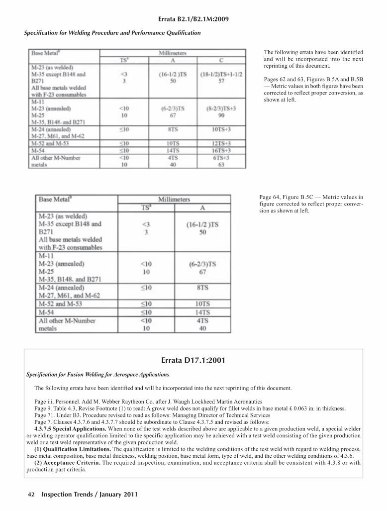
Errata B2.1/B2.1M:2009
Specification for Welding Procedure and Performance Qualification
The following errata have been identified
and will be incorporated into the next
reprinting of this document.
Pages 62 and 63, Figures B.5A and B.5B
— Metric values in both figures have been
corrected to reflect proper conversion, as
shown at left.
Page 64, Figure B.5C — Metric values in
figure corrected to reflect proper conver-
sion as shown at left.
Errata D17.1:2001
Specification for Fusion Welding for Aerospace Applications
The following errata have been identified and will be incorporated into the next reprinting of this document.
Page iii. Personnel. Add M. Webber Raytheon Co. after J. Waugh Lockheed Martin Aeronautics
Page 9. Table 4.3, Revise Footnote (1) to read: A grove weld does not qualify for fillet welds in base metal £ 0.063 in. in thickness.
Page 71. Under B3. Procedure revised to read as follows: Managing Director of Technical Services
Page 7. Clauses 4.3.7.6 and 4.3.7.7 should be subordinate to Clause 4.3.7.5 and revised as follows:
4.3.7.5 Special Applications. When none of the test welds described above are applicable to a given production weld, a special welder
or welding operator qualification limited to the specific application may be achieved with a test weld consisting of the given production
weld or a test weld representative of the given production weld.
(1) Qualification Limitations. The qualification is limited to the welding conditions of the test weld with regard to welding process,
base metal composition, base metal thickness, welding position, base metal form, type of weld, and the other welding conditions of 4.3.6.
(2) Acceptance Criteria. The required inspection, examination, and acceptance criteria shall be consistent with 4.3.8 or with
production part criteria.
Inspection Trends / January 201142
Project1:FP_TEMP 12/22/10 4:15 PM Page 42
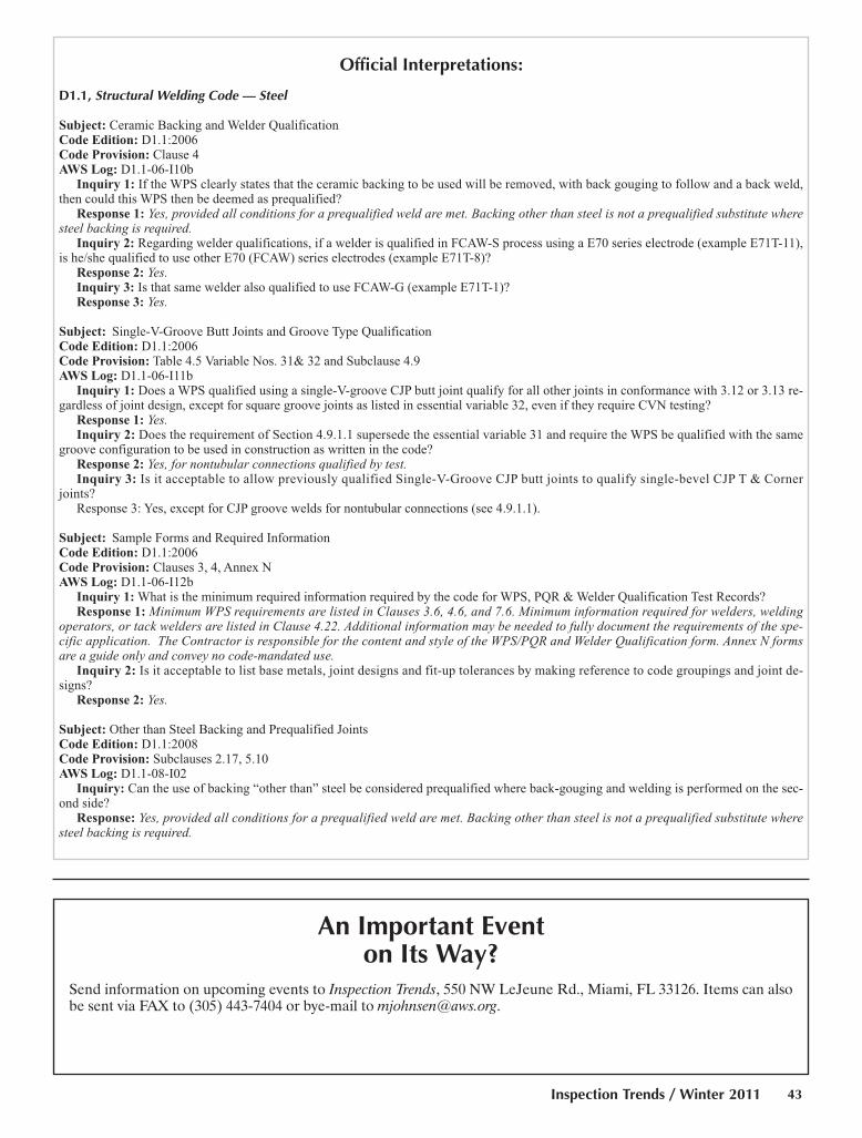
Official Interpretations:
D1.1, Structural Welding Code — Steel
Subject: Ceramic Backing and Welder Qualification Code Edition: D1.1:2006Code Provision: Clause 4AWS Log: D1.1-06-I10b
Inquiry 1: If the WPS clearly states that the ceramic backing to be used will be removed, with back gouging to follow and a back weld,then could this WPS then be deemed as prequalified?
Response 1: Yes, provided all conditions for a prequalified weld are met. Backing other than steel is not a prequalified substitute wheresteel backing is required.
Inquiry 2: Regarding welder qualifications, if a welder is qualified in FCAW-S process using a E70 series electrode (example E71T-11),is he/she qualified to use other E70 (FCAW) series electrodes (example E71T-8)?
Response 2: Yes.Inquiry 3: Is that same welder also qualified to use FCAW-G (example E71T-1)?Response 3: Yes.
Subject: Single-V-Groove Butt Joints and Groove Type Qualification Code Edition: D1.1:2006Code Provision: Table 4.5 Variable Nos. 31& 32 and Subclause 4.9AWS Log: D1.1-06-I11b
Inquiry 1: Does a WPS qualified using a single-V-groove CJP butt joint qualify for all other joints in conformance with 3.12 or 3.13 re-gardless of joint design, except for square groove joints as listed in essential variable 32, even if they require CVN testing?
Response 1: Yes.Inquiry 2: Does the requirement of Section 4.9.1.1 supersede the essential variable 31 and require the WPS be qualified with the same
groove configuration to be used in construction as written in the code?Response 2: Yes, for nontubular connections qualified by test.Inquiry 3: Is it acceptable to allow previously qualified Single-V-Groove CJP butt joints to qualify single-bevel CJP T & Corner
joints?Response 3: Yes, except for CJP groove welds for nontubular connections (see 4.9.1.1).
Subject: Sample Forms and Required Information Code Edition: D1.1:2006Code Provision: Clauses 3, 4, Annex NAWS Log: D1.1-06-I12b
Inquiry 1: What is the minimum required information required by the code for WPS, PQR & Welder Qualification Test Records?Response 1: Minimum WPS requirements are listed in Clauses 3.6, 4.6, and 7.6. Minimum information required for welders, welding
operators, or tack welders are listed in Clause 4.22. Additional information may be needed to fully document the requirements of the spe-cific application. The Contractor is responsible for the content and style of the WPS/PQR and Welder Qualification form. Annex N formsare a guide only and convey no code-mandated use.
Inquiry 2: Is it acceptable to list base metals, joint designs and fit-up tolerances by making reference to code groupings and joint de-signs?
Response 2: Yes.
Subject: Other than Steel Backing and Prequalified JointsCode Edition: D1.1:2008Code Provision: Subclauses 2.17, 5.10AWS Log: D1.1-08-I02
Inquiry: Can the use of backing “other than” steel be considered prequalified where back-gouging and welding is performed on the sec-ond side?
Response: Yes, provided all conditions for a prequalified weld are met. Backing other than steel is not a prequalified substitute wheresteel backing is required.
An Important Eventon Its Way?
Send information on upcoming events to Inspection Trends, 550 NW LeJeune Rd., Miami, FL 33126. Items can alsobe sent via FAX to (305) 443-7404 or bye-mail to [email protected].
Inspection Trends / Winter 2011 43
Page 43:FP_TEMP 12/22/10 4:21 PM Page 43
American Society of Nondestructive Testing . . . .11, 13
www.asnt.org . . . . . . . . . . . . . . . . . . . . . .800-222-2768
AWS Certification Services . . . . . . . . . . . . . . . . . .7, 41
www.aws.org . . . . . . . . . . . . . . . . . . . . . .800-443-9353
AWS Member Services . . . . . . . . . . . . . . . . .10, 12, 37
www.aws.org . . . . . . . . . . . . . . . . . . . . . .800-443-9353
FABTECH . . . . . . . . . . . . . . . . . . . . . . . . . . . . . . .OBC
www.aws.org . . . . . . . . . . . . . . . . . . . . . .800-443-9353
G.A.L. Gage Co. . . . . . . . . . . . . . . . . . . . . . . . . . . . . . .9
www.galgage.com . . . . . . . . . . . . . . . . . .269-465-5750
Iris Inspection Services, Inc. . . . . . . . . . . . . . . . . . . . .9
www.iris-inspection.com . . . . . . . . . . . . .800-940-1471
NDT Seals, Inc. . . . . . . . . . . . . . . . . . . . . . . . . . . . . . .9
www.ndtseals.com . . . . . . . . . . . . . . . . . .800-261-6261
Olympus NDT . . . . . . . . . . . . . . . . . . . . . . . . . . . . .IFC
www.olympusNDT.com . . . . . . . . . . . . .781-419-3900
Thermo Fisher Scientific/Niton Analyzers . . . . . . .IBC
www.thermo.com/niton . . . . . . . . . . . . . .978-670-7460
World Spec Online NDT Training . . . . . . . . . . . . . . .17
www.worldspec.org . . . . . . . . . . . . . . . . .877-506-7773
IFC = Inside Front Cover
IBC = Inside Back Cover
OBC = Outside Back Cover
Visit Our Interactive Ad Index: www.aws.org/ad-index
Business Cards
Business Products
Advertiser Index
Inspection Trends / January 201144
Construction Technical Services16350 Park Ten Place, Suite 238Houston, TX 77084
Steven T. SnyderTechnical Manager
AWS-SCWI, ASQ-CQA, ASNT NDT Level III, CSWIP-AUT-PA
Office: 281-578-6810 Cell: 504-931-9567 Email: [email protected] Web site: www.ctsisite.com
“Committed To Service”
jan 2011 it classified index:Layout 1 12/27/10 2:16 PM Page 44

©20
10 T
herm
o Fi
sher
Sci
enti
fic In
c. A
ll ri
ghts
rese
rved
.
To verify the integrity of your process sytems, take matters into your own hands.
The requirement for positive material identification (PMI)
in alloys used throughout the physical plant is more critical
than ever. Simply relying on spot testing of parts and
subassemblies is too risky and unacceptable. While that may
seem like a challenge, it’s now a surprisingly easy task thanks
to Thermo Scientific Niton XRF analyzers.
vessels
www.thermoscientific.com/niton.
Moving science forward
The all-new Thermo Scientific Niton XL2 GOLDD and Niton XL3t GOLDD+ join our
Speed, accuracy, value – either way, you gain the advantage.
For Info go to www.aws.org/ad-index
thermo fischer:FP_TEMP 12/22/10 7:57 AM Page C3

November 13 – 16, 2011McCormick Place North & South Halls | Chicago, IL USA
450,000 NSF Floor Space
30,000 Attendees
1,200 Exhibitors
For more information about exhibiting
or attending the event, log onto
www.fabtechexpo.com
North America’s largest metal forming, fabricating, welding, and finishing event
fabtech:FP_TEMP 12/22/10 8:45 AM Page C4