Embed Size (px)
Citation preview
Inspection System by Phased Array for Composite Materials
Applied to Aircraft Industry
JoãoAmorim, ULisboa, Lisboa, Portugal, [email protected]
ABSTRACT: The increasing use of composites in aircraft industry leads to the need for non-
destructive testing systems that are effective in the inspection and evaluation of these structures.
Since there is currently a lack of effective systems for inspecting composites, a system that is able to
inspect not only composite flat panels but also parts with complex geometries autonomously was
developed. This system consists in an instrumented tank that can perform inspections by immersion of
complex geometries with a system of five degrees of freedom, which is able to cover a scanning area
of approximately 3m2.
In order to validate the project a flat composite plate, with embedded and previously known defects,
was inspected with ultrasonic phased technique, using a LabVIEW program with pre-defined
trajectories. This program was developed especially for this system. The final results demonstrate the
efficiency the inspection obtained through this system in terms of inspection sensitivity.
KEY-WORDS Automated inspection system; Aeronautic industry; Composites; Nondestructive testing;
Phased Array; Inspection by immersion
1. INTRODUCTION
Non-destructive testing (NDT) is a procedure that allows parts inspection without affecting their
functionality. According the type of material, these tests need to be adjusted order to prevent damage.
(1) (2) Ultrasonic inspection technique is usually the most appropriate type of inspection for difficult
defects. (3) (4) Phased Array is an advanced variant of the ultrasonic technique and it can be applied
in any scenario where traditionally conventional ultrasounds are applied. This method allows the user
to control parameters such as the emission angle of the beam and the focal length, there by increasing
the probability of detection defects. (5) (6)
The inspection technique by contact is specific for manual testing, and the inspection by immersion is
specific for tests by automated systems. In this type of inspection, the probe and the part to be
inspected are both immersed to ensure an optimal and uniform coupling. This type of inspection can
achieve faster productivity in terms of quality control and can be automated, and a single probe can be
used with various angles of incidence. Since there is no direct contact between the workpiece and the
probe the probe wear does not exist. (2) (7)
Some constraints are still found when trying to perform a NDT inspection with Phased Array. Among
these restrictions the complexity of the geometry of the components play an important role, because
they lead to poor performance of probes since the characteristics of the beam cannot be preserved.
The thickness variation during the examination can be problematic because there will be the need of
different inspection setups to ensure the inspection effectiveness.
To tackle this problem, a technique based on an iterative process of data acquisition by measuring the
times of flight of the wave was implemented. A law of delay is calculated through these times and is
applied to all the elements of the probe. This technique is called Adaptive Surface Ultrasounds
(SAUL). This technique allows using the same probe to analyze various structures of complex
geometry through an iterative algorithm. With this approach a normal incidence of the beam in any
point of is achieved surface without the need of an adapted probe to the profile of the geometry. (8)
The most common defects of composites are debonding and delaminations. Delaminations usually
occur in the manufacture of the composite when some undesirable element lies between layers.
Debonding may come from an inefficient adhesion between of the composite layers or by the lack of
resin between the same elements. To detect these type of defects it is convenient that they are
oriented parallel to the plane of the probe.
Given these limitations abovementioned to the aim of the present work is to develop a flexible system
that will be adaptable to different inspection scenarios depending on its restrictions. The system will be
fully adjustable to complex geometries, as for example variations in the curvature radius along the
geometry profile.
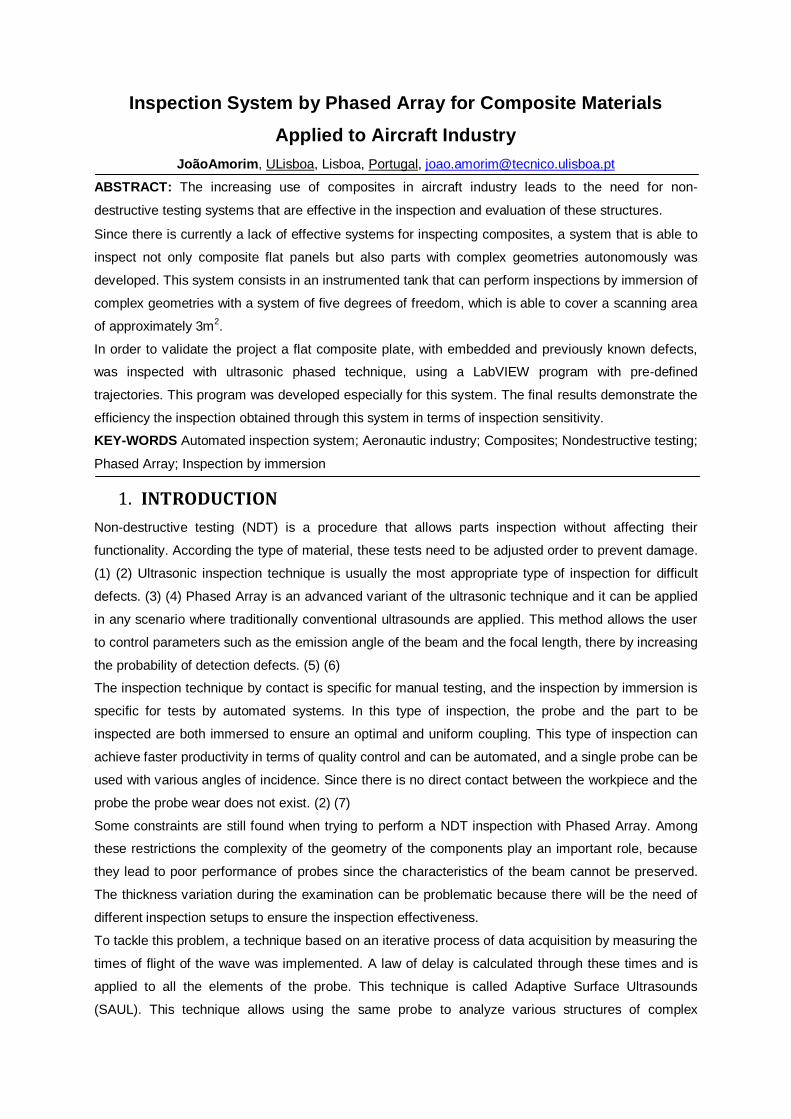
2. PROJECT
Aiming to build an inspection immersion system where it could be possible to inspect materials with
the Phased Array technique, it was proposed to design the following elements:
• A stainless steel tank with dimensions of 2500x1300 mm, with an area of 3 m 2, able to support a
head of water of 500 mm to inspect components using ultrasonic techniques;
• An autonomous system of water recirculation using a water pump and appropriate filters;
• A centralized control system, with all the electronics required for the handling of the probe;
• A system of linear actuators responsible for the movement of the X, Y and Z axes which could
achieve a speed of 100 mm/s with an accuracy of 0.1 mm;
• An arm, 700 mm long, connected to the vertical Z axis with the capacity to hold and adjust the
probe with two automated degrees of freedom.
Figure 1 - Project Summary
In paralell to the tank design several structural simulations, using Solidworks modeling tool, were
done, considering the appropriated load profile in order to obtain results about the performance of the
designed tank.

The final tank is presented in the following figures.
Figure 2 - Isometric view of the tank
With a water mass of about 2500 kg, the boundary conditions were defined in each face of the tank in
terms of the correspondent pressure. To the side metal sheets and the acrylic, the force applied was
based on the concept of hydrostatic pressure. In addition, the gravity the force was applied and the
supports of the tank were constrained in all directions.
The materials used in SolidWorks were:
• AISI 304 - Yield Stress= 206.8 MPa for all reinforcing bars and plates used
• Acrylic (Medium-high impact) - Yield Stress= 45MPa for the acrylic used in the front of the tank.
From the simulation, the following results were obtained:
Figure 3 - Distribution of stresses in the tank
Figure 4 - Distribution of deformations in the tank
The maximum stress value in the tank was 96.7 MPa and the maximum deformation was 1.49mm,
obtaining an overall safety factor of 3.21.
Another element designed was the coupling arm of the probe which is presented in the following
figures:

Figure 5 - Isometric view of probe holder arm
Through a set of bearings, as it can be seen in Figure 6, the independent movement in each degree of
freedom was achieved, obtained from the rotational motor and the tilt motor of probe.
Figure 6 - System for connection of motors
To fix the probe was necessary to use dedicated concepts, as is seen in Figure 7, not only to have a
system fix the probe but also to allow a precise lateral adjustment to perform the inspection.
Figure 7 - System for attaching the probe, with side adjustment
The final design on the complete system is shown in the following figure:

Figure 8 - Isometric View of the inspection system
3. CONSTRUCTION
After the material and components acquisition they were connected using welding processes. The
main process was the Tungsten Inert Gas (TIG) (9). Other processes such as Shielded Metal Arc
Welding (SMAW) (9) or Stud Welding (SW) (10) were also important during the construction of the
tank.
As TIG is very efficient to weld thin metal sheet, this process was extensively used for the majority of
the welds since it allows a more precise control of heat input obtaining high quality welding beads.
For the present case, weldings of 2 mm stainless steel sheets, it is desirable to use direct current with
direct polarity. In general the welding parameters were an Intensity 80 A, with gas rates of 10 l/min
using rods of filler material specific for the AISI 304 steel.
The welds were made with the back stepping welding technique, i.e. with limited advancement and
intervals in order to prevent a large heat input in the base material and thus to reduce the welding
distortion. (11)
Figure 9 - Final appearance of the beads after welding
To develop the water filling and recirculation system, different devices were purchased and
assembled. In Figure 10 is presented the recirculation system an its different elements.

Figure 10–Recirculating water system and pump
Table 1 - Legend of components in the recirculating water system
Item Name Description
1 16/12 BulkheadPush-to-
Connect Water input from the tank for recirculation.
2 16/12 BulkheadPush-to-
Connect Water input
3 Tap ½” Tap to open and close the flux of water from the tank.
4 Water filter Removes the impurities in the water..
5 16/12 Push-In ElbowSwivel
Accessory that leads the flux of water to the tank.
6 Check Valve Valve that allows the water to flow through it in only one direction
7 16/12 BulkheadPush-to-
Connect Water exit to the sewer.
8 8/6 BulkheadPush-to-
Connect Water output for the probes.
9 Pump Device that moves the water by mechanical action.Can recirculate the entire
water volume in about one hour.
The electrical system followed the same idea of the previous system, but having a special attention in
handling the components due to electric current flow.
The final design of the electrical and electronic engine control system, after the assembling of the
different components, is presented in Figure 11:
Figure 11 - Electrical system
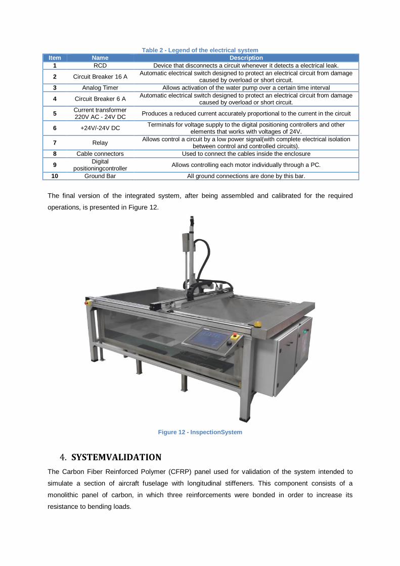
Table 2 - Legend of the electrical system
Item Name Description
1 RCD Device that disconnects a circuit whenever it detects a electrical leak.
2 Circuit Breaker 16 A Automatic electrical switch designed to protect an electrical circuit from damage
caused by overload or short circuit.
3 Analog Timer Allows activation of the water pump over a certain time interval
4 Circuit Breaker 6 A Automatic electrical switch designed to protect an electrical circuit from damage
caused by overload or short circuit.
5 Current transformer 220V AC - 24V DC
Produces a reduced current accurately proportional to the current in the circuit
6 +24V/-24V DC Terminals for voltage supply to the digital positioning controllers and other
elements that works with voltages of 24V.
7 Relay Allows control a circuit by a low power signal(with complete electrical isolation
between control and controlled circuits).
8 Cable connectors Used to connect the cables inside the enclosure
9 Digital
positioningcontroller Allows controlling each motor individually through a PC.
10 Ground Bar All ground connections are done by this bar.
The final version of the integrated system, after being assembled and calibrated for the required
operations, is presented in Figure 12.
Figure 12 - InspectionSystem
4. SYSTEMVALIDATION
The Carbon Fiber Reinforced Polymer (CFRP) panel used for validation of the system intended to
simulate a section of aircraft fuselage with longitudinal stiffeners. This component consists of a
monolithic panel of carbon, in which three reinforcements were bonded in order to increase its
resistance to bending loads.

Figure 13 - Dimensions for validation panel
During the panel inspection and the system validation, the panel was subjected to several mechanical
tests of fatigue and impact and nondestructive testing was performed between each testing phase.
Five impacts were made on the plate with different loads. These impacts as well the strain gauges are
shown in Figure 14:
Figure 14 - Validation panel with indication of the impacts and strain gauges
In Figure 15 and Figure 16 acquisitions made by a 10 MHz Phased Array probe are presented, which
represent the background echoes of the composite panel after the first cycle fatigue, and after the last
cycle fatigue, respectively.

Figure 15 - Acquisition of eco background after the first cycle of fatigue
Figure 16 - Acquisition of eco background after the last cycle fatigue
In the two figures squares are represented to assess the evolution of defects in the panel.
These squares represent:
• In squares 1 to 5 area number of pin-hole areas due to small lacks of resin;
• In square 1 and 5, there are flaws of delamination around the sensors
• In square 5 a defect due to the impact test can be seen.
Through the analysis of the two acquisitions, and due to the inspection system sensitivity, is possible
to verify that there is an increase in the monitored areas..
5. CONCLUSION
Regarding the different developments, it is worth noting that they have been implemented successfully
and on schedule.
Apart from to the acquired knowledge derived from the complete development, including all stages, of
a system capable of addressing the requirements initially defined, several contacts with various
suppliers of all elements required for the system were made, in order to compare the various options
and choose the best supplier in terms of cost and quality of the components

Concerning the system manufacturing the main conclusions are the following:
• A Stainless steel AISI 304 immersion tank with external dimensions of 1320mm by 2500mm was
successfully built.
• The recirculating water system was successfully assembled achieving a water recirculation time for
the entire tank of 1 hour.
• The electrical system was one of the components that required more effort due to its complexity. It
was possible to successfully manage the control system from a set of six motors which are part of
the inspection system.
• The linear actuators X, Y and Z are all very important to the system due to its accuracy and
function. With the actuators and the engines mounted it was found that the overall module complies
with the required precision and speed.
• The arm attached to the vertical axis Z was one of the most complex elements to design,
manufacture and assemble, due to its functional specifications. At the end this was able to rotate
and tilt the probe and it has a fine-tuning adjustment for the probe.
Although it was not originally planned, some acquisitions were made in composite pane in order to
prove the overall capability of the system developed. To make this task possible a program in
LabVIEW was developed in parallel that was able to operate the mechanical part of the phased array
inspection system. This program has several features, allowing the predefinition of different types of
customized scanning trajectories in order to inspect parts with complex geometry.
6. Bibliography
1. Almeida, Filomena Pinto, Barata, João e Barros, Pedro.Ensaios Não Destrutivos. Lisboa : ISQ,
1992. 972-9228-12-4.
2. Gómez, Ramírez, et al., et al.Métodos de Ensayos No Destructivos. Cuarta. Madrid : INTA. 84-
920798-2-7.
3. O´Brien, Robert L.Jefferson's Welding Encyclopedia. 18ª Edição. Miami : American Welding
Society, 1997. 0-87171-506-6.
4. Weman, Klas e Lindén, Gunnar.MIG Welding Guide. 1ª Edição . Cambridge : Woodhead
Publishing Limited, 2006. 978-1-85573-947-5.
5. [Online] [Citação: 8 de Setembro de 2013.] http://www.twi.co.uk/technologies/ndt/advanced-
ndt/phased-array-ultrasonic-testing/.
6. [Online] [Citação: 8 de Setembro de 2013.] http://www.ndt.net/article/panndt2007/papers/29.pdf .
7. León, Eduardo Gómez.Ensayos No Destrutivos - Ultrasonidos Nivel II. Madrid : Asociación
Española de Ensayos no Destructivos. 84-96169-92-8.
8. Robert, Sèbastien, et al., et al.Real Time Nondestrutive Testing of Composite Aeronautical
Structures With a Self-Adadptive Ultrasonic Technique. France : IEEE, 2012. 978-1-4577-1775-8/12.
9. Oliveira Santos, J. F. e Quintino, L.Processos de Soldadura. Lisboa : Edições Técnicas do
Instituto de Soldadura e Qualidade, 1997. Vol. I.
10. CENTER. Nelson Stud Welding. [Online] [Citação: 25 de 04 de 2014.]
http://www.centerindustrial.com/nelson-stud-welding/.
11. H., Dubbel, et al., et al.Manual Da Construcao de Maquinas. s.l. : Hemus , 1974.