Embed Size (px)
Citation preview

Engineering Standard Rolling Stock
ESR 0040
INSPECTION OF FREIGHT BOGIES
Version 1.1
Issued May 2013
Owner: Technical Specialist Rolling Stock Performance Standards
Approved Stephen White, Authorised Michael Uhlig, by: A/Manager, by: A/Chief Engineer Rolling Stock
Rolling Stock Access Integrity
Disclaimer This document was prepared for use on the RailCorp Network only. RailCorp makes no warranties, express or implied, that compliance with the contents of this document shall be sufficient to ensure safe systems or work or operation. It is the document user’s sole responsibility to ensure that thecopy of the document it is viewing is the current version of the document as in use by RailCorp. RailCorp accepts no liability whatsoever in relation to the use of this document by any party, and RailCorp excludes any liability which arises in any manner by the use of this document. Copyright The information in this document is protected by Copyright and no part of this document may be reproduced, altered,stored or transmitted by any person without the prior consent of RailCorp.
Engi
neer
ing
Stan
dard
UNCONTROLLED WHEN PRINTED Page 1 of 33
RailCorp Engineering Standard — Rolling Stock Inspection of freight bogies ESR 0040
Document control
Version Date Summary of change (RSS 0040) 1.0 Based on TRS 1010 2.0 May 2007 Reissued as a RailCorp Standard 2.1 May 2008 ESR references amended (ESR 0040) 1.0 June 2010 Reformatted and renumbered ESR 0040 1.1 May 2013 Issued
Summary of changes from previous version
Summary of change Section Version 1.1 Minor reformatting Missing figures inserted Requirement for bogie code and number to be painted on sideframes added 5.1.1 Reference to Figure 19 amended to Figure 18 5.8.2.3.4 Bearing colour coding updated 5.8.3 Reference to “ESR 0030” amended to read “ESR 0330” 5.10.3
© RailCorp Page 2 of 33 Issued May 2013 UNCONTROLLED WHEN PRINTED Version 1.1

RailCorp Engineering Standard — Rolling Stock Inspection of freight bogies ESR 0040
Contents
1 Introduction .............................................................................................................................5
2 Scope........................................................................................................................................5
3 Application...............................................................................................................................5
4 Reference documents.............................................................................................................5
4.1 RailCorp standards ...................................................................................................................5
4.2 RailCorp drawings.....................................................................................................................5
5 Inspection requirements ........................................................................................................5
5.1 Markings....................................................................................................................................5
5.1.1 Bogie code and number.............................................................................................6
5.1.2 DI date .......................................................................................................................6
5.1.3 OH date .....................................................................................................................6
5.1.4 Grease dates .............................................................................................................6
5.1.5 BI date........................................................................................................................6
5.1.6 Summary ...................................................................................................................6
5.2 Wheels ......................................................................................................................................7
5.3 Axles..........................................................................................................................................7
5.3.1 Inspection ..................................................................................................................7
5.3.2 Summary ...................................................................................................................8
5.4 Frame inspection.......................................................................................................................8
5.4.1 Frame.........................................................................................................................9
5.4.2 Wear plates................................................................................................................9
5.4.3 Brake beam guides....................................................................................................9
5.4.4 Pedestal roof liners ....................................................................................................9
5.4.5 Summary .................................................................................................................10
5.5 Bolster inspection....................................................................................................................10
5.5.1 Bolster casting .........................................................................................................11
5.5.2 Wear Plates (not including centre liner)...................................................................11
5.5.3 Centre liner ..............................................................................................................11
5.5.4 Gibs..........................................................................................................................11
5.5.5 Summary .................................................................................................................12
5.6 Damping devices.....................................................................................................................13
5.6.1 Bolster mounted friction wedges on ride control bogies..........................................13
5.6.1.1 Inspection .................................................................................................13
5.6.1.2 Limits ........................................................................................................13
5.6.2 Frame mounted friction wedges as found on National type bogies ........................15
5.6.2.1 Inspection .................................................................................................16
5.6.2.2 Limits ........................................................................................................16
5.7 Springs ....................................................................................................................................17
5.7.1 Inspection ................................................................................................................17
5.7.1.1 Broken springs .........................................................................................17
5.7.1.2 Seating .....................................................................................................18
5.7.1.3 Solid height...............................................................................................18
5.7.2 Summary .................................................................................................................18
© RailCorp Page 3 of 33 Issued May 2013 UNCONTROLLED WHEN PRINTED Version 1.1
RailCorp Engineering Standard — Rolling Stock Inspection of freight bogies ESR 0040
5.8 Bearings ..................................................................................................................................19
5.8.1 Axlebox bearing assemblies....................................................................................19
5.8.1.1 Axlebox components ................................................................................19
5.8.1.2 Inspection of axleboxes............................................................................19
5.8.1.3 Wheelsets not installed in bogies.............................................................20
5.8.2 Package unit bearings .............................................................................................22
5.8.2.1 Components .............................................................................................22
5.8.2.2 Inspection of package units......................................................................22
5.8.2.3 Wheelsets not installed in bogies.............................................................25
5.8.2.4 Repair procedure......................................................................................26
5.8.3 Grease dates and colours .......................................................................................27
5.8.3.1 Axlebox bearings......................................................................................27
5.8.3.2 Package unit bearings..............................................................................27
5.8.4 Bearing retention devices ........................................................................................27
5.8.4.1 Inspection .................................................................................................27
5.8.5 Package unit bearing adaptors................................................................................29
5.8.5.1 Adaptor types ...........................................................................................29
5.8.5.2 Adaptor inspection....................................................................................29
5.9 Radial clearance .....................................................................................................................30
5.9.1 Side bearer setting gauges......................................................................................31
5.10 Brakegear................................................................................................................................32
5.10.1 Brakebeams.............................................................................................................32
5.10.2 Summary .................................................................................................................33
5.10.3 Alignment of brake blocks .......................................................................................33
5.10.4 Brakegear security...................................................................................................33
© RailCorp Page 4 of 33 Issued May 2013 UNCONTROLLED WHEN PRINTED Version 1.1

RailCorp Engineering Standard — Rolling Stock Inspection of freight bogies ESR 0040
1 Introduction All RailCorp infrastructure maintenance freight vehicles are to be maintained to the freight rolling stock maintenance standards.
2 Scope This standard details the minimum requirements for the in field examination of standard three piece freight bogies to ensure the safe operation on the RailCorp network.
3 Application This standard is to be used by maintenance staff when inspecting three piece freight bogies.
4 Reference documents
4.1 RailCorp standards ESR 0032 Bearing reference manual
ESR 0043. Coil spring groups
ESR 0312 Security of brakegear
ESR 0330 Wheel defect manual
ESR 0331 Wheel & axle reference manual
4.2 RailCorp drawings 203-953 Side bearing clearances
207-650 Friction wedge height gauge
306-395 Side bearer clearance gauge
406-916 Bogie side bearing clearance gauge
5 Inspection requirements
5.1 Markings Dates are marked on bogies to indicate when overhaul has been carried out.
© RailCorp Page 5 of 33 Issued May 2013 UNCONTROLLED WHEN PRINTED Version 1.1

RailCorp Engineering Standard — Rolling Stock Inspection of freight bogies ESR 0040
XLA 2222
Figure 1 Bogie markings
5.1.1 Bogie code and number The bogie code and number shall be stencilled on the both bogie sideframes.
5.1.2 DI date Note: The DI date is no longer stencilled on the bogie. The DI is due at the next R2 maintenance.
5.1.3 OH date The overhaul date of the bogie is usually stencilled on the right hand pedestal of the bogie.
This date indicates the date and location of when the last overhaul was carried out and indicates the maintenance history of the bogie.
There is no action required for overhaul dates.
5.1.4 Grease dates It is now RailCorp practice to colour code axleboxes to indicate when bearings are due or overdue for greasing. Refer to 5.8.3 for grease dates.
It was past practice to stencil grease dates on the right hand pedestal. This date is no longer required to be stencilled on the bogie.
5.1.5 BI date A BI (bearing inspection) date is sometimes stencilled on the barrel of the wheelset. On package unit bearings the BI date should also be stamped on the endcap locking plate.
This date indicates when the bearings were last inspected with the wheelset removed from the bogie and is usually done at wheel turning.
For action on this date see 5.8.3.
5.1.6 Summary Condition Action Comments DW dates No action History only Grease date See 5.8.3 BI Date See 5.8.3
Table 1
© RailCorp Page 6 of 33 Issued May 2013 UNCONTROLLED WHEN PRINTED Version 1.1

RailCorp Engineering Standard — Rolling Stock Inspection of freight bogies ESR 0040
5.2 Wheels Wheel condition shall have a partial examination carried out in accordance with ESR 0330.
If required, as defined in ESR 0331, wheels shall be measured.
5.3 Axles Axles shall be inspected, as a fractured axle will almost certainly lead to a derailment.
Figure 2
For axles in service the examination is made with the wheels and bearings installed and only the visible portion of the axle is inspected.
Figure 3
5.3.1 Inspection Axles shall be inspected for visible defects on the portion between the wheelseats, the axle barrel.
Defects consist of scoring, grooves, scratches, flame cutting marks, welding, grinding, chisel marks or similar indentations.
Any vehicle with an axle defect greater than 3 mm deep which has a sharp edge or base, no radius evident on either side or at the base of the imperfection, has a pronounced lip adjacent the imperfection or you have any doubt as to the depth of the defect, shall be red carded for wheelset replacement.
Any vehicle with an axle defect greater than 3 mm deep but less then 5 mm deep which has smooth even wear, is well radiused and does not have any other imperfection such as a lip or roll-over on the edge of the damaged area shall be green carded for repairs. If there is any doubt as to the classification of the defect the defects shall be treated as above.
© RailCorp Page 7 of 33 Issued May 2013 UNCONTROLLED WHEN PRINTED Version 1.1
5.4
Condition Action Comments
Sharp edged defect greater than 3mm deep
Red card Wheelset will be replaced
Smooth edged defect greater than 3 mm deep but less than 5 mm deep
Green card Wheelset will be replaced
Any defect greater than 5 mm Red card Wheelset will be replaced
Axle visible cracks or fractured Red card Wheelset will be replaced
Axle bent Red card Wheelset will be replaced
RailCorp Engineering Standard — Rolling Stock Inspection of freight bogies ESR 0040
Any vehicle with an axle defect greater than 5mm deep shall be red carded for repairs.
There shall be no visible cracks in the axle body, either between the wheel seats or adjacent to the wheel hub. Axles with visible cracks shall be red carded for wheelset replacement.
Vehicles with axles which are bent shall be red carded for wheelset replacement. Axles may be checked for straightness by measuring back to back measurement in accordance with ESR 0331.
5.3.2 Summary
Table 2
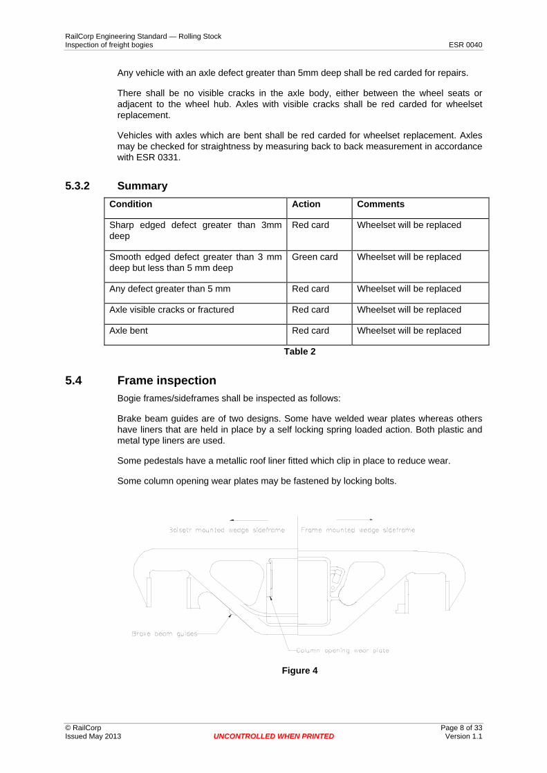
Frame inspection Bogie frames/sideframes shall be inspected as follows:
Brake beam guides are of two designs. Some have welded wear plates whereas others have liners that are held in place by a self locking spring loaded action. Both plastic andmetal type liners are used.
Some pedestals have a metallic roof liner fitted which clip in place to reduce wear.
Some column opening wear plates may be fastened by locking bolts.
Figure 4
© RailCorp Page 8 of 33 Issued May 2013 UNCONTROLLED WHEN PRINTED Version 1.1

RailCorp Engineering Standard — Rolling Stock Inspection of freight bogies ESR 0040
5.4.1 Frame Bogie frames shall be visually inspected for cracks. If any cracks are found the vehicle shall be red carded and the bogie replaced.
If the bogie frame is obviously bent the vehicle shall be red carded and the bogie replaced.
5.4.2 Wear plates Wear plates welded to frames shall be checked for cracked welds.
If the welds on the outside of the wear plates are completely cracked the vehicles shall be green carded for repairs.
If the wear plate has small pieces, less than 20 mm, chipped or broken away from the edge or corners, the vehicle shall be green carded for repairs.
If the wear plate is missing, cracked more than 20 mm, or dislodged, the vehicle shall be red carded and the bogie replaced.
For wear plates fastened by bolts, if one or two of the bolts are loose or missing the vehicle shall be green carded for repairs. If more than two bolts are loose or missing the vehicle shall be red carded for repairs.
5.4.3 Brake beam guides If the brake beam guides are missing, broken or worn to a thickness less than 1 mm, the vehicle shall be green carded. When at a repair location the wear plates shall be repaired or replaced.
If there is the possibility of the wear plate being dislodged and preventing the brakes from working the vehicle may continue in service with the brakes isolated and the brakes must not be dragging. When at a repair location the wear plates shall be repaired or replaced.
5.4.4 Pedestal roof liners Some bogies are fitted with a clip on pedestal roof liner. If the liner is cracked or missing the vehicle shall be green carded for repairs.
If the liner is broken the vehicle shall be red carded for replacement of the liners.
Where fitted, bogies must be fitted with all four wear liners. There must be four liners fitted or none.
© RailCorp Page 9 of 33 Issued May 2013 UNCONTROLLED WHEN PRINTED Version 1.1

5.5
Condition Action Comments
Sideframe cracked or bent Red card Bogie will be replaced and repaired
Outside wear plate welds fully cracked
Green card Bogie will be repaired
Wear plate small part edge or corner chipped or broken
Green card Bogie will be repaired
Wear plate cracked more than 20mm, missing or dislodged
Red card Bogie will be replaced and repaired
Wear plate bolts one or two missing
Green card Bogie will be repaired
Wear plate bolts more than two missing
Red card Bogie will be repaired
Brake beam guide worn to less than 1mm
Green card Bogie will be repaired
Brakebeam guide possibility of jamming brakes
Green card Brakes must be isolated. Brakes must not be dragging.
Pedestal roof liners cracked or missing
Green card Bogie will be repaired
Pedestal roof liners broken Red card Bogie will be repaired
RailCorp Engineering Standard — Rolling Stock Inspection of freight bogies ESR 0040
5.4.5 Summary
Table 3
Bolster inspection Inspection of the bolster is necessary as it is a critical load bearing member of the bogie.
Wear plates are also attached that may dislodge and cause the bolster to jam in the frame.
Figure 5
© RailCorp Page 10 of 33 Issued May 2013 UNCONTROLLED WHEN PRINTED Version 1.1

RailCorp Engineering Standard — Rolling Stock Inspection of freight bogies ESR 0040
5.5.1 Bolster casting Bolsters shall be visually inspected for cracks. If any cracks are found the vehicle shall be red carded.
If the bolster is obviously bent the vehicle shall be red carded for repairs
5.5.2 Wear Plates (not including centre liner) Wear plates welded to bolsters shall be checked for cracked welds.
If the welds on the outside of the wear plates are completely cracked the vehicles shall be green carded for repairs.
If the wear plate has small pieces, less than 20 mm, chipped or broken away from the edge or corners, the vehicle shall be green carded for repairs.
If the wear plate is missing, cracked more than 20 mm, or dislodged the vehicle shall be red carded for repairs.
For wear plates fastened by bolts, if one or two of the bolts are loose or missing the vehicle shall be green carded for repairs. If more than two bolts are loose or missing the vehicle shall be red carded for repairs.
5.5.3 Centre liner Cracked centre liner welds are not required to be marked off for repairs.
If the centre liner has more than 2 pieces broken out from the liner the vehicle shall be red carded for repairs.
If centre liners have more than two cracks the vehicle shall be green carded for repairs.
If there is less than 3 mm vertical clearance, but no contact, between the bolster centre liner and the body centre casting the vehicle shall be green carded for repairs.
If there is no clearance at any point between the bolster centre liner and the body centre casting the vehicle shall be red carded. The bogie or vehicle centre casting will be replaced or repaired.
5.5.4 Gibs If the thickness of any gib is less than 10 mm the vehicle shall be green carded for repairs.
If any gib is missing, except by design, the vehicle shall be red carded.
© RailCorp Page 11 of 33 Issued May 2013 UNCONTROLLED WHEN PRINTED Version 1.1
RailCorp Engineering Standard — Rolling Stock Inspection of freight bogies ESR 0040
5.5.5 Summary Condition Action Comments
Bolster cracked or bent Red card Bogie will be replaced and repaired.
Outside wear plate welds fully cracked Green card Bogie will be repaired
Wear plate small part edge or corner chipped or broken
Green card Bogie will be repaired
Wear plate cracked more than 20mm, missing or dislodged
Red card Bogie will be replaced and repaired
Wear plate bolts one or two missing Green card Bogie will be repaired
Wear plate bolts more than two missing Red card Bogie will be replaced and repaired
Centre liner two or more cracks Green card Bogie will be repaired
Less than 3 mm vertical between bolster centre casting and vehicle body casting
Green card Bogie will be repaired
Vertical contact between bolster centre casting and vehicle body casting
Red card Bogie or vehicle centre casting will be replaced or repaired
Gibs less than 10 mm thick Green card Bogie will be repaired
Gibs missing Red card Bogie will be replaced and repaired
Table 4
© RailCorp Page 12 of 33 Issued May 2013 UNCONTROLLED WHEN PRINTED Version 1.1

RailCorp Engineering Standard — Rolling Stock Inspection of freight bogies ESR 0040
5.6 Damping devices
5.6.1 Bolster mounted friction wedges on ride control bogies
Figure 6
This type of friction wedge arrangement is fitted to 3 piece freight bogies as shown in Figure 6. Ride Control bogies have the friction wedges housed in the bolster. The spring which forces the wedge out is separate from the wedge and this spring does not carry any of the vehicle load.
5.6.1.1 Inspection Wedge heights are required to be visually checked for correct average height and variation.
Wedges shall be inspected for wear notches.
If there is any doubt to the suitability for service, measurements shall be taken.
5.6.1.2 Limits Condition Action Comments
Average wedge height less than 46 mm
No action OK for service
Average wedge height equal to or greater than 46 mm but
less than 50 mm
Green card for repairs in the tare
condition
Tranship load. Bogie will be repaired or replaced.
Average wedge height equal to or greater than 50 mm
Red card vehicle Bogie to be repaired or replaced.
Wear notch not visible Green card for repairs
Bogie will be repaired or replaced.
Wedge height variation greater than 20 mm
Green card for repairs
Bogie will be repaired or replaced.
Table 5
© RailCorp Page 13 of 33 Issued May 2013 UNCONTROLLED WHEN PRINTED Version 1.1
RailCorp Engineering Standard — Rolling Stock Inspection of freight bogies ESR 0040
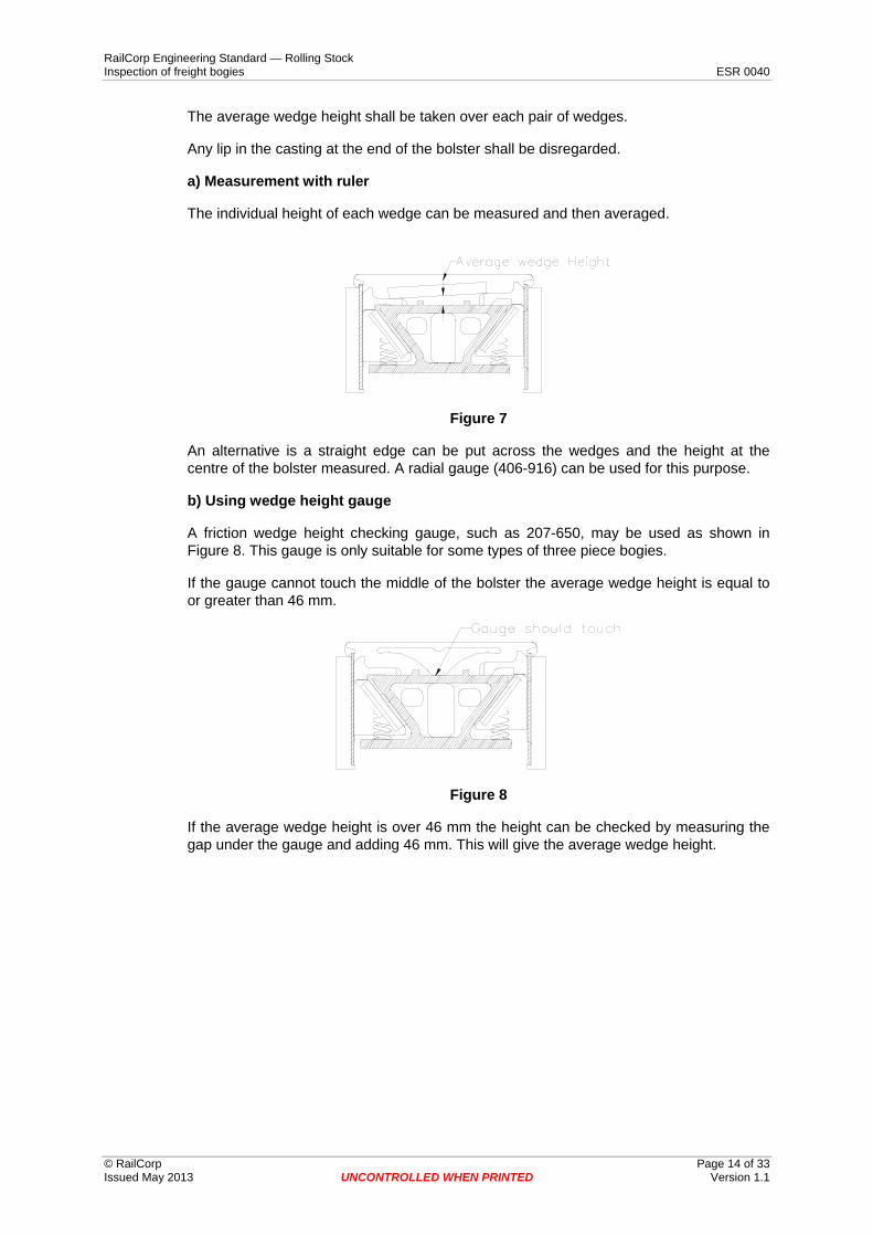
The average wedge height shall be taken over each pair of wedges.
Any lip in the casting at the end of the bolster shall be disregarded.
a) Measurement with ruler
The individual height of each wedge can be measured and then averaged.
Figure 7
An alternative is a straight edge can be put across the wedges and the height at the centre of the bolster measured. A radial gauge (406-916) can be used for this purpose.
b) Using wedge height gauge
A friction wedge height checking gauge, such as 207-650, may be used as shown in Figure 8. This gauge is only suitable for some types of three piece bogies.
If the gauge cannot touch the middle of the bolster the average wedge height is equal to or greater than 46 mm.
Figure 8
If the average wedge height is over 46 mm the height can be checked by measuring the gap under the gauge and adding 46 mm. This will give the average wedge height.
© RailCorp Page 14 of 33 Issued May 2013 UNCONTROLLED WHEN PRINTED Version 1.1

RailCorp Engineering Standard — Rolling Stock Inspection of freight bogies ESR 0040
c) Wedge height variation
Figure 9
The wedge height variation can be measured by using a ruler or radial gauge (406-916).
d) Wear notch
Wedges have a wear notch cast into the side friction face positioned as shown in Figure 9and shown in more detail on the wedge in Figure 10.
This notch is an indication of the wear on the friction wedge casting.
Figure 10
5.6.2 Frame mounted friction wedges as found on National type bogies Frame mounted friction wedges are fitted to National type three piece bogies.
Figure 11
© RailCorp Page 15 of 33 Issued May 2013 UNCONTROLLED WHEN PRINTED Version 1.1

Condition Action Comments
Bottom of wedge to spring base greater than 150 mm
No action Fit for service
Bottom of wedge to spring base greater than 145 mm but less than or equal to 150 mm
Green card for repairs in tare condition
Tranship load. Bogie will be replaced and repaired.
Bottom of wedge to spring base less than or equal to 145 mm
Red card Bogie will be replaced and repaired.
Wear notch less than 1 mm Green card for repairs Bogie will be replaced and repaired.
RailCorp Engineering Standard — Rolling Stock Inspection of freight bogies ESR 0040
5.6.2.1 Inspection Wedge heights are required to be visually checked for correct height.
Wedges shall be inspected for wear notches.
If there is any doubt to the suitability for service, measurements shall be taken.
5.6.2.2 Limits
Table 6
a) Measurement with ruler
The distance from the bottom of the spring seat to the bottom of the friction wedge can be measured as shown in Figure 12.
Figure 12
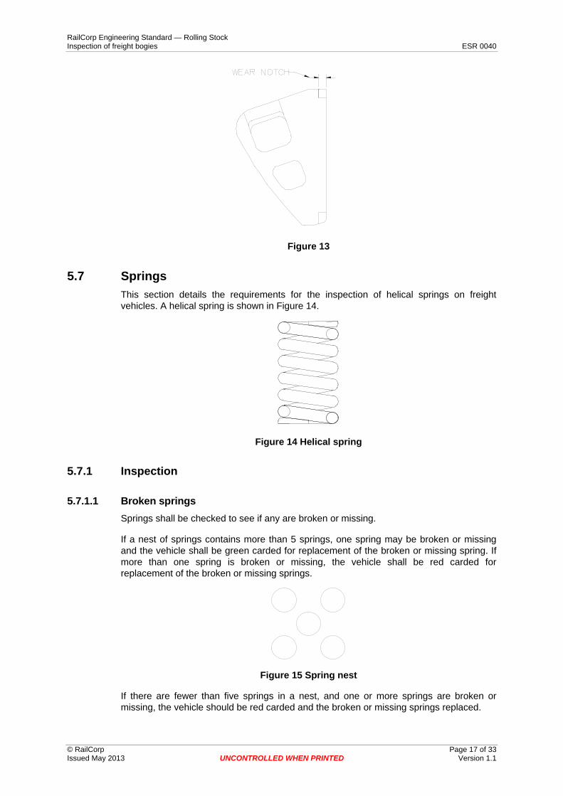
b) Wear notch
Snubbers have a wear notch cast into the side friction face positioned as shown in Figure12 and shown in more detail on the wedge in Figure 13.
This notch is an indication of the wear on the friction wedge casting.
The wear notch can be measured with the aid of a ruler.
© RailCorp Page 16 of 33 Issued May 2013 UNCONTROLLED WHEN PRINTED Version 1.1
RailCorp Engineering Standard — Rolling Stock Inspection of freight bogies ESR 0040
Figure 13
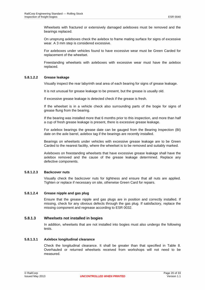
5.7 Springs This section details the requirements for the inspection of helical springs on freight vehicles. A helical spring is shown in Figure 14.
Figure 14 Helical spring
5.7.1 Inspection
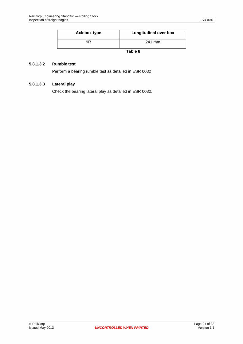
5.7.1.1 Broken springs Springs shall be checked to see if any are broken or missing.
If a nest of springs contains more than 5 springs, one spring may be broken or missing and the vehicle shall be green carded for replacement of the broken or missing spring. If more than one spring is broken or missing, the vehicle shall be red carded for replacement of the broken or missing springs.
Figure 15 Spring nest
If there are fewer than five springs in a nest, and one or more springs are broken or missing, the vehicle should be red carded and the broken or missing springs replaced.
© RailCorp Page 17 of 33 Issued May 2013 UNCONTROLLED WHEN PRINTED Version 1.1

RailCorp Engineering Standard — Rolling Stock Inspection of freight bogies ESR 0040
5.7.1.2 Seating Springs shall be checked to see that all springs are seating correctly.
Springs should sit with full contact on the top and bottom seat.
Sometimes the springs may become dislodged or cocked in service as shown in Figure16.
Figure 16 Dislodged or cocked spring
An attempt should be made to reposition dislodged or cocked springs. This should bedone with the vehicle in the empty condition.
Care should be taken that the springs are not damaged while reseating.
After reseating the springs should be checked for damage.
5.7.1.3 Solid height The minimum height between spring coils in the loaded or unloaded condition shall be 1mm.
Vehicles with springs with less than 1 mm between the coils shall be red carded.
Lack of clearance can be attributed to overloading, loss of spring tension or the incorrecttype or number of springs.
For correct type and number of springs see ESR 0043.
5.7.2 Summary Condition Action Comments
More than 5 springs in nest, 1 spring broken or missing
Green card Broken or missing springs will be changed
More than 5 springs in nest, more than 1 spring broken or missing
Red card Broken or missing springs will be changed or bogie replaced
Less than 5 springs in nest 1, or more springs broken or missing
Red card Broken or missing springs will be changed or bogie replaced
Spring unseated, dislodged or cocked
Red card. Reseat spring in the unloaded condition
Minimum clearance between coils less than 1 mm
Red Card Check for overloading, type and number of springs, spring tension
Table 7
© RailCorp Page 18 of 33 Issued May 2013 UNCONTROLLED WHEN PRINTED Version 1.1

RailCorp Engineering Standard — Rolling Stock Inspection of freight bogies ESR 0040
5.8 Bearings
5.8.1 Axlebox bearing assemblies Axlebox bearings shall be inspected in vehicles in service, on wheelsets before being installed in bogies and at wheel turning.
5.8.1.1 Axlebox components
5.8.1.1.1 Unsprung type axlebox
This type of axlebox is used in three piece bogies with direct contact between the crown of the axlebox and the pedestal roof of the bogie sideframe (e.g. 9R).
The components that are to be examined for this type of axlebox are shown in Figure 17.
Figure 17
5.8.1.2 Inspection of axleboxes
5.8.1.2.1 Axlebox housing
Visually inspect the axlebox housing and note any signs of cracking or extensive physical damage that is likely to effect the safe operation of the bearing.
Any vehicles found to have fractured or extensively damaged axleboxes must be Red Carded. The wheelset must be replaced.
© RailCorp Page 19 of 33 Issued May 2013 UNCONTROLLED WHEN PRINTED Version 1.1
RailCorp Engineering Standard — Rolling Stock Inspection of freight bogies ESR 0040
Wheelsets with fractured or extensively damaged axleboxes must be removed and the bearings replaced.
On unsprung axleboxes check the axlebox to frame mating surface for signs of excessive wear. A 3 mm step is considered excessive.
For axleboxes under vehicles found to have excessive wear must be Green Carded for replacement of the wheelset.
Freestanding wheelsets with axleboxes with excessive wear must have the axlebox replaced.
5.8.1.2.2 Grease leakage
Visually inspect the rear labyrinth seal area of each bearing for signs of grease leakage.
It is not unusual for grease leakage to be present, but the grease is usually old.
If excessive grease leakage is detected check if the grease is fresh.
If the wheelset is in a vehicle check also surrounding parts of the bogie for signs of grease flung from the bearing.
If the bearing was installed more that 6 months prior to this inspection, and more than half a cup of fresh grease leakage is present, there is excessive grease leakage.
For axlebox bearings the grease date can be gauged from the Bearing Inspection (BI) date on the axle barrel, axlebox tag if the bearings are recently installed.
Bearings on wheelsets under vehicles with excessive grease leakage are to be Green Carded to the nearest facility, where the wheelset is to be removed and suitably marked.
Axleboxes on freestanding wheelsets that have excessive grease leakage shall have the axlebox removed and the cause of the grease leakage determined. Replace any defective components.
5.8.1.2.3 Backcover nuts
Visually check the backcover nuts for tightness and ensure that all nuts are applied. Tighten or replace if necessary on site, otherwise Green Card for repairs.
5.8.1.2.4 Grease nipple and gas plug
Ensure that the grease nipple and gas plugs are in position and correctly installed. If missing, check for any obvious defects through the gas plug. If satisfactory, replace the missing component and regrease according to ESR 0032.
5.8.1.3 Wheelsets not installed in bogies In addition, wheelsets that are not installed into bogies must also undergo the following tests.
5.8.1.3.1 Axlebox longitudinal clearance
Check the longitudinal clearance. It shall be greater than that specified in Table 8. Overhauled or returned wheelsets received from workshops will not need to be measured.
© RailCorp Page 20 of 33 Issued May 2013 UNCONTROLLED WHEN PRINTED Version 1.1
RailCorp Engineering Standard — Rolling Stock Inspection of freight bogies ESR 0040
Axlebox type Longitudinal over box
9R 241 mm
Table 8
5.8.1.3.2 Rumble test
Perform a bearing rumble test as detailed in ESR 0032
5.8.1.3.3 Lateral play
Check the bearing lateral play as detailed in ESR 0032.
© RailCorp Page 21 of 33 Issued May 2013 UNCONTROLLED WHEN PRINTED Version 1.1
RailCorp Engineering Standard — Rolling Stock Inspection of freight bogies ESR 0040
5.8.2 Package unit bearings
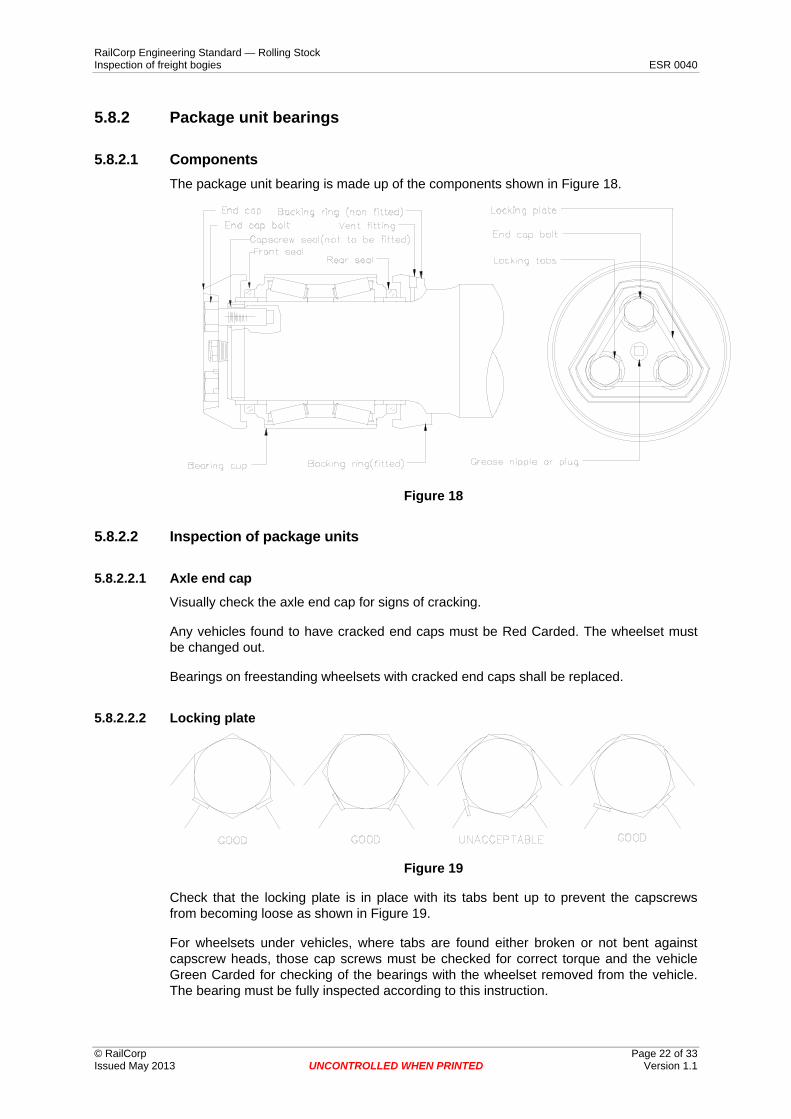
5.8.2.1 Components The package unit bearing is made up of the components shown in Figure 18.
Figure 18
5.8.2.2 Inspection of package units
5.8.2.2.1 Axle end cap
Visually check the axle end cap for signs of cracking.
Any vehicles found to have cracked end caps must be Red Carded. The wheelset must be changed out.
Bearings on freestanding wheelsets with cracked end caps shall be replaced.
5.8.2.2.2 Locking plate
Figure 19
Check that the locking plate is in place with its tabs bent up to prevent the capscrews from becoming loose as shown in Figure 19.
For wheelsets under vehicles, where tabs are found either broken or not bent against capscrew heads, those cap screws must be checked for correct torque and the vehicle Green Carded for checking of the bearings with the wheelset removed from the vehicle. The bearing must be fully inspected according to this instruction.
© RailCorp Page 22 of 33 Issued May 2013 UNCONTROLLED WHEN PRINTED Version 1.1
RailCorp Engineering Standard — Rolling Stock Inspection of freight bogies ESR 0040
For freestanding wheelsets, where tabs are found not bent against capscrew heads or broken must have the locking plate replaced and the bearing must be fully inspected according to this instruction.
In all cases when fitting new locking plates stamp the axle number and bearing date from the existing locking plate, onto the new locking plate being fitted.
5.8.2.2.3 Capscrews
Visually check to see that all cap screws appear secure.
For bearings on wheelsets under vehicles, if any capscrew is loose so that it can be rotated by hand or missing, the vehicle is to be Red Carded and the wheelset replaced.
Bearings on freestanding wheelsets, with finger tight or missing capscrews, shall be replaced.
5.8.2.2.4 Bearing cup
Visually inspect the exposed part of the bearing cup.
Note any chips, dents or cracks, particularly at the outer edges of the cup, near the seal.
Bearings on wheelsets under vehicles with chips, dents or cracks in the bearings must beRed Carded. The wheelset must be replaced. Wheelsets are to be suitably marked.
Bearings on freestanding wheelsets with chips, dents or cracks must be replaced.
5.8.2.2.5 Grease leakage at front seal
Visually inspect the seal area of each bearing for signs of grease leakage.
If signs of grease are detected, wipe the seal in the area of the leak with a blunt instrument, and check if the grease is fresh.
If in a vehicle check also the surrounding parts of the bogie, such as the frame adaptor,for signs of grease flung from a rotating bearing.
If the bearing was installed more that 6 months prior to this inspection, and more thanone tablespoon of fresh grease leakage is present, there is excessive grease leakage.
The bearing installation date is located on the locking plate on the bearing end cap.
Bearings on wheelsets under vehicles with excessive grease leakage are to be Green Carded to the nearest facility, where the wheelset is to be removed and suitably marked.
Bearings on freestanding wheelsets with excessive grease leakage must be replaced.
5.8.2.2.6 Grease leakage at rear seal
Behind the bogie frame, visually inspect the rear seal for signs of grease leakage.
If the bearing was installed more that 6 months prior to this inspection, and more than one tablespoon of fresh grease leakage is present, there is excessive grease leakage.
The bearing installation date is located on the locking plate on the bearing end cap.
Bearings on wheelsets under vehicles with excessive grease leakage are to be Green Carded to the nearest facility, where the wheelset is to be removed and suitably marked.
© RailCorp Page 23 of 33 Issued May 2013 UNCONTROLLED WHEN PRINTED Version 1.1

RailCorp Engineering Standard — Rolling Stock Inspection of freight bogies ESR 0040
Bearings on freestanding wheelsets with excessive grease leakage must be replaced.
5.8.2.2.7 Dented seals
Visually inspect the full circumference of all seals for dents causing the seals to become out of round where the seal meets the bearing cup.
Bearings on wheelsets under vehicles detected with seals damaged in this way must be Red Carded. The wheelset concerned is to be replaced and suitably marked.
Bearings on freestanding wheelsets with dented seals must be replaced
5.8.2.2.8 Seals out of position
Visually inspect all seals to ensure that they are seated squarely to the end of the bearing cup as shown in Figure 20.
Bearings on wheelsets under vehicles detected with seals out of position must be Red Carded. The wheelset must be replaced and suitably marked.
Bearings on freestanding wheelsets with out of position seals must be replaced.
Figure 20
5.8.2.2.9 Lateral movement of seals
Using the thumb and index finger of each hand, or a suitable probe that will not damage the seal, check if the seal can be moved laterally, (in a direction parallel to the axle). as shown in Figure 21.
Bearings on wheelsets under vehicles found to have loose seals must be Red Carded. The wheelset is to be replaced and is suitably marked.
Figure 21
Bearings on freestanding wheelsets found to have loose seals must be replaced.
© RailCorp Page 24 of 33 Issued May 2013 UNCONTROLLED WHEN PRINTED Version 1.1

RailCorp Engineering Standard — Rolling Stock Inspection of freight bogies ESR 0040
5.8.2.2.10 Rotation of seals
Using the thumb and index finger of each hand, or a suitable probe that will not damage the seal, check if the seal can be rotated as shown in Figure 22.
Bearings on wheelsets under vehicles found to have loose seals must be Red Carded to the nearest depot, where the wheelset is to be removed and suitably marked.
Bearings on freestanding wheelsets with loose seals must be replaced.
Figure 22
5.8.2.2.11 Bearings out of date
It will not be required for examiners to specifically look for bearing dates.
At repair locations determine the latest bearing inspection (BI) or installation date from the locking plate.
From this date determine how many years the wheelset has been in service. If it exceeds the period stated in ESR 0032 the wheelset shall be replaced and sent for workshop attention. The wheelset should be suitably marked.
Freestanding wheelsets with out of date bearings shall have the bearings replaced.
Wheelsets with no installation dates are to be treated the same as for bearings that are out of date.
5.8.2.3 Wheelsets not installed in bogies In addition, wheelsets to be installed into bogies must also undergo the following tests.
5.8.2.3.1 Rumble test
Perform a bearing rumble test as detailed in ESR 0032.
5.8.2.3.2 Lateral play
Check the bearing lateral play as detailed in ESR 0032.
5.8.2.3.3 Fitted and non fitted backing rings
Check the backing ring to see if it will rotate by hand.
If the backing ring can be rotated the bearing must be replaced.
© RailCorp Page 25 of 33 Issued May 2013 UNCONTROLLED WHEN PRINTED Version 1.1
RailCorp Engineering Standard — Rolling Stock Inspection of freight bogies ESR 0040
5.8.2.3.4 Non fitted backing ring
For bearings fitted with non fitted backing rings (see Figure 18 for detail) attempt to insert a 0.05 mm (0.002") feeler gauge between the bearing backing ring and the axle fillet.
If the feeler gauge can be inserted more than 3 mm the bearing must be replaced.
5.8.2.4 Repair procedure When fitting new locking plates, replacing end caps, replacing capscrews or replacing bearings, the requirements of ESR 0032 shall be met.
© RailCorp Page 26 of 33 Issued May 2013 UNCONTROLLED WHEN PRINTED Version 1.1
RailCorp Engineering Standard — Rolling Stock Inspection of freight bogies ESR 0040
5.8.3 Grease dates and colours
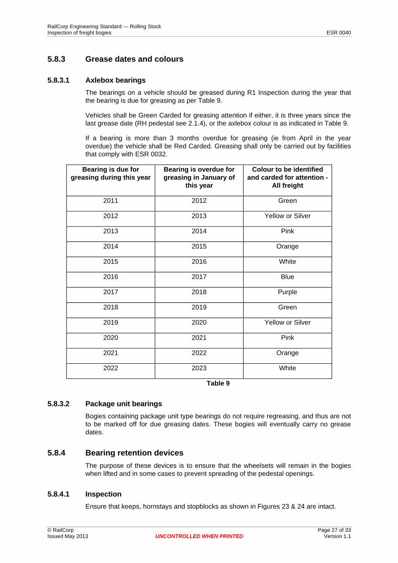
5.8.3.1 Axlebox bearings The bearings on a vehicle should be greased during R1 Inspection during the year that the bearing is due for greasing as per Table 9.
Vehicles shall be Green Carded for greasing attention if either, it is three years since the last grease date (RH pedestal see 2.1.4), or the axlebox colour is as indicated in Table 9.
If a bearing is more than 3 months overdue for greasing (ie from April in the year overdue) the vehicle shall be Red Carded. Greasing shall only be carried out by facilities that comply with ESR 0032.
Bearing is due for greasing during this year
Bearing is overdue for greasing in January of
this year
Colour to be identified and carded for attention -
All freight
2011 2012 Green
2012 2013 Yellow or Silver
2013 2014 Pink
2014 2015 Orange
2015 2016 White
2016 2017 Blue
2017 2018 Purple
2018 2019 Green
2019 2020 Yellow or Silver
2020 2021 Pink
2021 2022 Orange
2022 2023 White
Table 9
5.8.3.2 Package unit bearings Bogies containing package unit type bearings do not require regreasing, and thus are not to be marked off for due greasing dates. These bogies will eventually carry no grease dates.
5.8.4 Bearing retention devices The purpose of these devices is to ensure that the wheelsets will remain in the bogies when lifted and in some cases to prevent spreading of the pedestal openings.
5.8.4.1 Inspection Ensure that keeps, hornstays and stopblocks as shown in Figures 23 & 24 are intact.
© RailCorp Page 27 of 33 Issued May 2013 UNCONTROLLED WHEN PRINTED Version 1.1

RailCorp Engineering Standard — Rolling Stock Inspection of freight bogies ESR 0040
Hornstays with stop blocks are to be fitted with the stopblocks uppermost as shown in Figure 24.
If any of these are missing or loose, tighten or replace on site if possible, otherwise green card to the nearest repair facility for repairs.
Figure 23
Block must be upper most
Figure 24
© RailCorp Page 28 of 33 Issued May 2013 UNCONTROLLED WHEN PRINTED Version 1.1
RailCorp Engineering Standard — Rolling Stock Inspection of freight bogies ESR 0040
5.8.5 Package unit bearing adaptors Checking of adaptors is necessary because defects can provide inadequate support to the bearing which can cause the bearing to fail.
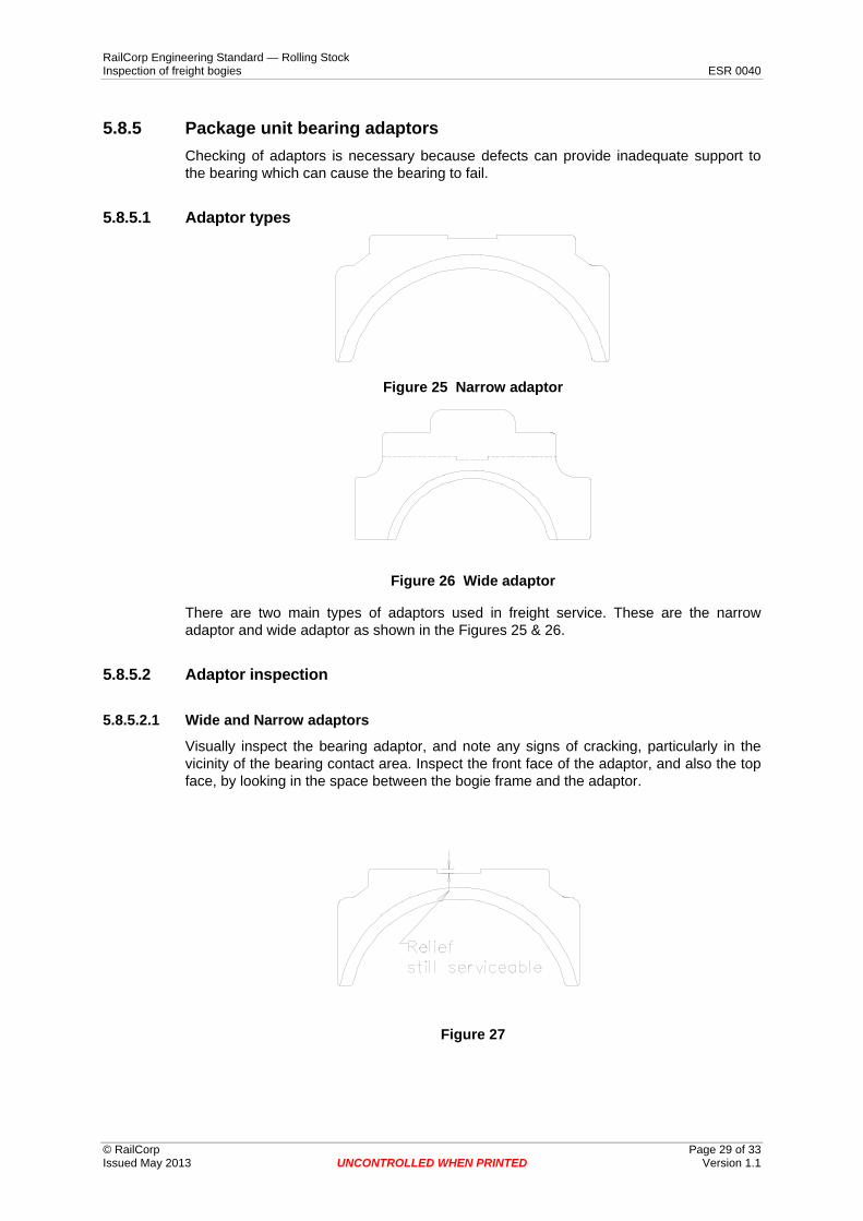
5.8.5.1 Adaptor types
Figure 25 Narrow adaptor
Figure 26 Wide adaptor
There are two main types of adaptors used in freight service. These are the narrow adaptor and wide adaptor as shown in the Figures 25 & 26.
5.8.5.2 Adaptor inspection
5.8.5.2.1 Wide and Narrow adaptors
Visually inspect the bearing adaptor, and note any signs of cracking, particularly in the vicinity of the bearing contact area. Inspect the front face of the adaptor, and also the top face, by looking in the space between the bogie frame and the adaptor.
Figure 27
© RailCorp Page 29 of 33 Issued May 2013 UNCONTROLLED WHEN PRINTED Version 1.1

RailCorp Engineering Standard — Rolling Stock Inspection of freight bogies ESR 0040
Figure 28
If the crown on top of the adaptor has worn to such a condition that the sideframes contact on the relief portions as shown in Figure 28, the adaptors must be replaced. Green Card to the nearest repair facility for replacement.
Any vehicles found to have cracks in the bearing adaptor must be Red Carded for replacement of the adaptor. A full inspection of the bearing under the damaged bearing adaptor must be made, as described in ESR 0032, before fitting a replacement bearing adaptor.
5.8.5.2.2 Adaptor seating
Check that the bearing adaptor is sitting squarely on the bearing cup as shown in Figure 29.
There must be contact between the bearing cup and bearing adaptor at both the inner and outer wear pads of the adaptor.
Figure 29
Any vehicles found to have the bearing adaptor not sitting square to the bearing cup, must be Red Carded so that a detailed inspection of the bearing shall be carried out according to ESR 0032 with the wheelset removed from the vehicle.
Inspect endcap and backing ring for signs of scoring which would indicate a misplaced adaptor in service. Any bearing which shows signs of the adaptor being displaced in service must be Red Carded for a full bearing inspection according to ESR 0032 with the wheelset removed from the vehicle.
Radial clearance Field staff are required to visually check side bearer clearance during train examination. If by the visual check clearances are judged to be outside required limits, the clearances are to be checked using the side bearer clearance taper gauge, drawing 406-916 latest issue.
© RailCorp Page 30 of 33 Issued May 2013 UNCONTROLLED WHEN PRINTED Version 1.1
5.9
RailCorp Engineering Standard — Rolling Stock Inspection of freight bogies ESR 0040
Freight vehicles are to be marked off for adjustment of side bearer clearances if more than 2 mm outside the following, the 2 mm allowing for inaccuracies and inconsistencies in the field measurements:
Group number Total clearance per bogie (mm)
(add both sides)
Minimum Maximum
Freight wagons 19 29
Table 10
Because of uneven track in yards, marking off is to be determined from the total side bearer clearance rather than individual clearances each side of the bolster.
Vehicles found to have less than the required minimum clearance shall be fitted with slotted shims between the upper and lower centre castings as necessary to achieve correct clearances for transit to the nearest suitable repair location for attention.
The slotted shims shall be 290 mm nominal diameter for 305 mm centre castings, 340 mm nominal diameter for 356 mm centre castings, and 3 mm thick.
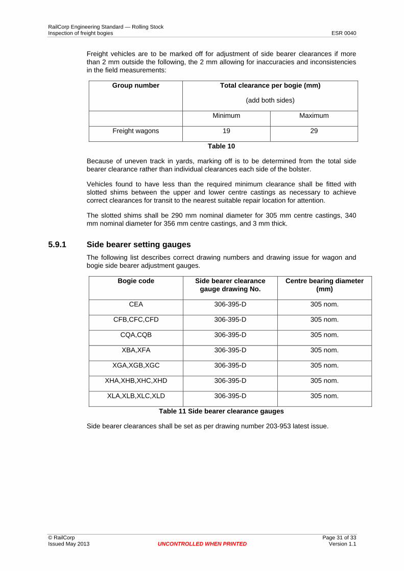
5.9.1 Side bearer setting gauges The following list describes correct drawing numbers and drawing issue for wagon and bogie side bearer adjustment gauges.
Bogie code Side bearer clearance gauge drawing No.
Centre bearing diameter (mm)
CEA 306-395-D 305 nom.
CFB,CFC,CFD 306-395-D 305 nom.
CQA,CQB 306-395-D 305 nom.
XBA,XFA 306-395-D 305 nom.
XGA,XGB,XGC 306-395-D 305 nom.
XHA,XHB,XHC,XHD 306-395-D 305 nom.
XLA,XLB,XLC,XLD 306-395-D 305 nom.
Table 11 Side bearer clearance gauges
Side bearer clearances shall be set as per drawing number 203-953 latest issue.
© RailCorp Page 31 of 33 Issued May 2013 UNCONTROLLED WHEN PRINTED Version 1.1
RailCorp Engineering Standard — Rolling Stock Inspection of freight bogies ESR 0040
5.10 Brakegear
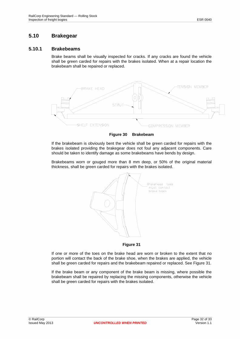
5.10.1 Brakebeams Brake beams shall be visually inspected for cracks. If any cracks are found the vehicle shall be green carded for repairs with the brakes isolated. When at a repair location the brakebeam shall be repaired or replaced.
Figure 30 Brakebeam
If the brakebeam is obviously bent the vehicle shall be green carded for repairs with the brakes isolated providing the brakegear does not foul any adjacent components. Care should be taken to identify damage as some brakebeams have bends by design.
Brakebeams worn or gouged more than 8 mm deep, or 50% of the original material thickness, shall be green carded for repairs with the brakes isolated.
Figure 31
If one or more of the toes on the brake head are worn or broken to the extent that no portion will contact the back of the brake shoe, when the brakes are applied, the vehicle shall be green carded for repairs and the brakebeam repaired or replaced. See Figure 31.
If the brake beam or any component of the brake beam is missing, where possible the brakebeam shall be repaired by replacing the missing components, otherwise the vehicle shall be green carded for repairs with the brakes isolated.
© RailCorp Page 32 of 33 Issued May 2013 UNCONTROLLED WHEN PRINTED Version 1.1

RailCorp Engineering Standard — Rolling Stock Inspection of freight bogies ESR 0040
5.10.2 Summary Condition Action Comments
Brakebeam cracked or bent Green card Brakes must be isolated
Brakebeam worn more than 8 mm or 50% of original material thickness
Green card Brakes must be isolated
Brakehead toes not contacting Green card Brakes must be isolated
Components missing Repair or green card
Brakes must be isolated if green carded
Table 12
5.10.3 Alignment of brake blocks Inspect brake blocks to ensure that they do not overhang the edge of the wheel. Refer to ESR 0330.
5.10.4 Brakegear security Inspect the security of all brakegear in accordance with ESR 0312.
© RailCorp Page 33 of 33 Issued May 2013 UNCONTROLLED WHEN PRINTED Version 1.1