Embed Size (px)
Citation preview

Innovative Solutions for Intersection of TBM Tunnel and Station in Riyadh Line 5 Metro
Gonzalo RAMOS SCHNEIDER PhD Peng CEng MICE
Full Professor. Department of Civil and Environmental Engineering. Universitat Politècnica de Catalunya – BarcelonaTech (UPC). Jordi Girona 1-3, 08034 Barcelona, Spain. email: [email protected] – Corresponding autor
Angel GARCIA-FONTANET MOLINA PhD PEng CEng MICE
Director at PRO GEO Geotechnical Consultants SL. Plà de l’Estany 22. 08192 Sant Quirze del Vallès, Spain. email: [email protected]
Victor TORRALBA MENDIOLA
Civil Engineer, MSc. Project Director at Tunnel and Bridge Technologies SL. Gran Via Carles III 98, Barcelona, Spain. Email: [email protected]
Javier AINCHIL LAVIN
Civil Engineer, MSc. Design and Construction Manager at FAST Consortium. FCC Construccion. Avenida del Camino de Santiago 40. 28050. Madrid, Spain. Email: [email protected]
ABSTRACT
One of the main problems when constructing a metro line using a tunnel boring machine (TBM) is the coordination of the construction of the tunnel with the excavation of the stations that it will intersect. The drilling speed of the tunnel varies from the predicted one, it being possible to reach the stations before their complete excavation. This paper presents a solution to this problem, one which has been implemented in the Riyadh Metro L5. This solution allows the construction of the tunnel and the later excavation of the station, while maintaining the operation of the TBM and the tunnel lining.
Keywords: TBM Tunnel, Station Construction, Precast Lining
1. Introduction
Line 5 of the Riyadh Metro (Saudi Arabia) belongs to the package awarded to the FAST Consortium, of which FCC Construccion is a partner and responsible for its construction. Other partners in the Consortium are Samsung C&T, Strukton, Alstom, and local company Freysinnet. Line 5 consists of a TBM tunnel about 12.9 km long and 12 stations built in open cut. This paper focuses on the problems encountered in the intersections between tunnel and stations. Thanks to the magnificent progression of the tunnel, which has even received an international award (TBM Team Award 2016), it reached the stations on dates prior to those planned. The tunnel passed before the stations were excavated. For this reason, the problem of attempting to simultaneously work in the tunnel and, consequently, keeping the lining, while excavating the stations and beginning the erection of their interior structure arose.
This paper presents the problem, the adopted solutions and the analyses developed for their complete design.
2. Literature review

The construction of underground stations combined with the construction of the tunnel itself has always been a problem. Several station construction procedures exist, such as cut and cover with different variations (Liu, 2000), NATM with different approaches (Fang, 2012), CAPS (Sadaghiani, 2010), BPA (Liu, 2016) and others. Nevertheless, to combine station and tunnel construction is normally something to be avoided. Typically, the station excavation is completed before the tunnel is drilled or, on the contrary, the excavation of the station is stopped until the tunnel is finished.
Some researchers have studied a similar problem, as Li (2016), but not for precast segmental linings.
In order to simultaneously excavate the stations and keep working inside the tunnel, complete structural analyses of the segmental lining had to be performed. Analysis of precast linings can be developed using the Elastic Equation Method (ACI, 2014), Beam-Spring Method (Ngoc, 2013; Teachavorasinskin, 2010) or FEM or DEM simulations (Arnau, 2015). In this case, a beam-spring approach has been used because it is precise enough to allow many calculations, while changing the position of the joints and with different load combinations.
3. Project and planning
Line 5 runs southwards from its Depot located in King Abdullah Road close to the Ministry of Education until the Nations Park in Central Riyadh. Through its 13 kilometer length it includes 12 underground stations, running mostly under King Abdulaziz Street which is one of the main avenues of the capital pf the Kingdom (see figure 1). Works started in October 2013 and all major infrastructures are currently finished.
Figure 1. Layout of Riyadh Line 5
4. Geological and geotechnical summary
In general terms, Riyadh geology is defined by a karstic environment with local presence of sinkholes and cavities. Rock mass is pretty massive with an almost horizontal layering. In addition, rock mass weathering degree and presence of discontinuities decrease with depth.
The geological units present in Line 5 area are the following: Jurassic deposits, Cretacious deposits and Quaternary deposits.
The Jurassic deposits are formed by the Jubaila unit (usually defined in the project as JJ) and the Arab formation, which is in contact with the cretaceous units. The later formation has two units: Breccia complex (J1a) and Carbonate facies (J1c).
The Cretacious deposits are composed by three formations from base to top: Suliay formation (C2), Yamama and Buwaib formations (C1). The Suliay formation is composed of compacted micritic to sparitic limestone with calcarenite and coquina beds.
The Quaternary deposits are composed of the following soil formations: Sheet Gravel (Qgy) and Wadi Alluvium (Qtz, Qty). The first one is composed of unconsolidated superficial deposits of gravel, sands and silts. The Wadi Alluvium deposits are well-sorted sands.
Finally, other Quaternary deposits are the karstic fill materials (Q1c). They originate from the dissolution processes of limestone, leaving reddish to brown clays and silt deposits with limestone clast that fill karstic voids at depth.
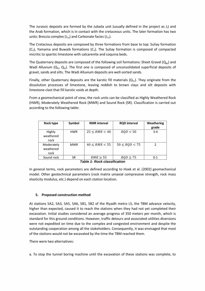
From a geomechanical point of view, the rock units can be classified as Highly Weathered Rock (HWR), Moderately Weathered Rock (MWR) and Sound Rock (SR). Classification is carried out according to the following table:
Rock type Symbol RMR interval RQD interval Weathering grade
Highly weathered
rock
HWR 25 ≤ 𝑅𝑅𝑅𝑅𝑅𝑅 < 40 𝑅𝑅𝑅𝑅𝑅𝑅 < 50 3-4
Moderately weathered
rock
MWR 40 ≤ 𝑅𝑅𝑅𝑅𝑅𝑅 < 55 50 ≤ 𝑅𝑅𝑅𝑅𝑅𝑅 < 75 2
Sound rock SR 𝑅𝑅𝑅𝑅𝑅𝑅 ≥ 55 𝑅𝑅𝑅𝑅𝑅𝑅 ≥ 75 0-1 Table 1- Rock classification
In general terms, rock parameters are defined according to Hoek et al. (2002) geomechanical model. Other geotechnical parameters (rock matrix uniaxial compressive strength, rock mass elasticity modulus, etc.) depend on each station location.
5. Proposed construction method
At stations 5A2, 5A3, 5A5, 5A6, 5B1, 5B2 of the Riyadh metro L5, the TBM advance velocity, higher than expected, caused it to reach the stations when they had not yet completed their excavation. Initial studies considered an average progress of 350 meters per month, which is standard for this ground conditions. However, traffic detours and associated utilities diversions were not expedited on time due to the complex and congested environment and despite the outstanding cooperation among all the stakeholders. Consequently, it was envisaged that most of the stations would not be excavated by the time the TBM reached them.
There were two alternatives:
a. To stop the tunnel boring machine until the excavation of these stations was complete, to

be able to erect the internal structure of the station before the tunnel crossed them. This alternative had very high economic and term costs that made it unfeasible.
b. To construct the tunnel through the stations, which according to the project conditions prevented the excavation of the stations to continue, as the minimum overburden was fixed as 3 m. Obviously, this solution also had economic and time costs.
As a result, the technical challenge was to continue the excavation of the stations while maintaining the tunnel operating under construction. Figure 2 shows the constructive procedure in which the execution of the tunnel is compatible with that of the station.

Figure 2. Construction Phases of the tunnel and stations
The construction procedure, as shown in figure 2, included:
a. Excavation up to the tunnel crown (Phases 1 and 2). b. Excavation around the tunnel and stabilization of the lining (Phase 3) c. Construction of the outer parts of the station countervault while the tunnel works
continue inside the lining (Phase 3) d. Erection of the lateral parts of the station structure (Phases 4, 5 and 6) e. When the tunnel works finish and all the installations inside the lining are removed,
the lining is dismantled (Phase 7). f. Contruction of the central part of the countervault (Phase 7) g. Erection of the central part of the station structure using precast elements (Phase 8)
As is well known, lining works by shape thanks to the confinement provided by the surrounding ground. Without that confinement, the lining is structurally a mechanism, and would collapse. Consequently, it was essential to make the ring stable in a provisional and evolutionary way and without interfering with all the installations and internal traffic inherent to the execution of the tunnel.
The tunnel is formed by 7 segment rings, with inner diameter of 8.70 m, thickness of 350 mm and an average length of ring of 1.60 m. There are 19 different ring positions. Reinforced concrete, with a segment longitudinal reinforcement of 11Φ12 per side (1.60m segment width) is used.
Two solutions, a first purely structural one and a second solution with geotechnical interaction, were adopted to make the tunnel lining stable while the excavation was progressing around it.
6. Lining stabilization
6.1. First method
In order not to interfere with the works of the tunnel, only the extrados of the lining could be affected. To keep the lining stable, when the soil was excavated, it was necessary to assure some bending strength to the longitudinal joints, to avoid collapse. The lining longitudinal joints were bolted during construction, and the capacity of the bolts was used to get that

capacity until the joints could be strengthened. It is usual to remove the bolts very early after gap injection. In this case, the bolts were kept in place right up until the lining was removed.
SAP2000 software was used for structural modelling; analyzing the structure as evolutionary through the option "nonlinear staged construction analysis". The model was a single ring, but after an initial analysis the three positions, 1, 6 and 12 were considered the most significant, where the key segment was placed at the crown, at the horizontal diameter and at the lowest possible position (See figure 3).
Figure 3. Ring positions analyzed. The shaded segment is the key
The modulus of lateral and vertical subgrade reaction for a moderately weathered rock are 200000 kN/m3 and 300000 kN/m3. In the analyses the ground is modeled by non-linear springs that operate only in compression. For the joints, the flexural stiffness corresponding to the joint-bolt assembly obtained from a moment-curvature analysis was introduced. Given the uncertainties always inherent to ballast coefficients, a sensitivity analysis of the horizontal module was also performed, which is the one that really influences the problem, adopting extreme values of 50000 kN/m3 and of 1000000 kN/m3. The springs are withdrawn as the ground is excavated.
In addition to the self-weight of the lining, a punctual load of 4.45 kN at the crown of the tunnel was included, being the weight of the ventilation pipe, and a live load corresponding to equipment of 20 kN/m2 was also considered. Earth-moving equipment (excavator, trucks,…) can be placed on one side or both sides of the tunnel. An active soil coefficient of 0.217 was adopted. Also, the load of the tunnel supply train has been included. In addition, at the final configuration, when the tunnel and station under construction coexist, an accidental vertical load of 100 kN was considered at the tunnel crown and a horizontal load of 100 kN was included at the horizontal diameter. These were accidental loads which can come from impacts during the construction of the station lateral structure. All loads have been factored according to EC2.
Firstly an analysis was done on whether the tunnel could be stable just considering the bolts at the longitudinal joints. As expected, the bolts were not able, without any other measure, to stabilize the rings.

Then, the construction sequence for the excavation and stabilization, shown in figure 4, was developed.
Small Trench to reach the ring crown
Excavation of a 0.5 m deep layer
Excavation 0.5 m deep over the ring
Excavation of a 0.5 m deep layer
Strengthening of existing radial joints from extrados. Concrete blocks are used.
Excavation of successive 0.5 m deep layers up to the tunnel axis.
Concrete block

Strengthening of the radial joints from the extrados. Steel plates are added
Excavation of the berm to permit the construction of the station
Figure 4. Excavation procedure
As the tunnel remained in construction, installations and supply train could not be dismantled. So, all the strengthening operations of the joints had to be performed from the extrados of the joints. The simplest way was to use a steel plate, anchored by epoxy fixed steel bolts. A similar solution with a steel plate for a different problem, but anchored through an epoxy resin, was used by Zhao (2016). This solution is optimal if the bending moment acting at the joint produces tensile forces in the extrados (see figure 5).
Figure 5. Strengthening of a radial joint at the extrados by a steel plate
If the bending moment at the joint produces opening at the intrados (for example at crown), a solution with a steel plate in the extrados is useless. The best solution would be a steel plate in the intrados, but the position of the ventilation pipe blocks its installation. The only way to act from the extrados is to use a concrete block (figure 6). That block was anchored to both adjacent segments by steel rebars with epoxy. The block was able to resist the expected bending moments.
Steel plates

Figure 6. Concrete blocks strengthening
As there were 19 different positions of the ring joints, it was essential to determine a simple criterion for each case. That criterion is, that the joints placed in an arch of 90º centered in the crown should be strengthened by concrete blocks. The rest of the joints should be strengthened by steel plates. This criterion was checked for all the possible solutions (see Figure 7).
Figure 7. Criterion for joint strengthening. All joints in Zone A are stregthened by concrete blocks and in Zone B by steel plates.

A special zone is the transition between tunnel and station. In that area the tunnel suddenly changes from a section which is confined by the ground to another which is not, resulting in quite different displacements of the rings. Those differences could cause problems in the circumferential joints.
In order to study that transition, a finite element 3D analysis was performed. The lining was modelled by shell elements and boundary conditions, fixing all the possible displacements, modelling the confinement of the soil. Figure 8 shows the bending moment due to ovalization.
Certainly, there is a distortion of the excavated rings which produce internal forces at the circumferential joint with the first tunnel ring. Nevertheless, maximum bending moments is 110 mkN/m, which can be resisted with a safety factor of 1.91. The shear forces could be resisted by the dowels of the segments connecting adjacent rings. The thrust force of the TBM, which is important for this phenomenon and favorable, was neglected in order to be conservative.
Figure 8. Bending moments due to ovalizationat the transition zone
Finally a stability analysis of the berm was performed using Plaxis 2D (see Figure 9).

Figure 9. Geomechanical model results. Total displacements contours with the loads of a supply train. Maximum value: 5.22 mm
The solution was used with great success (figures 10 and 11). It was used in stations 5A2, 5B1, 5B2, 5A3 and 5A5 (see fiure 1).
Figure 10. Tunnel crown and lateral excavation with the joints already strenghtened

Figure 11. Bottom slab and internal structure of the station is being built
6.2. Second method
The previously described method was a total success. Nevertheless the strengthening of the joints simultaneously with the excavation was quite time consuming. Furthermore, during the excavation of some of the stations it was possible to observe that the quality of the rock was better than expected. In fact, and according to the field data, most of the excavation was carried out in Moderately Weathered Rock (MWR) or Sound Rock (SR). This allowed an improvement in the geotechnical parameters that resulted in better data from the geomechanical models. An example of the analyzed data is shown in figure 12.
Figure 12. Geological Strenght Index (GSI) estimation from field data. Symbols correspond values that arise from site estimations while lines correspond to the GSI mean value for each geotechnical unit together with a standard deviation confidence
interval.

As already explained, the behavior of a ring is adequate when confined. Following that idea, it was possible to determine the minimum rock thickness around the tunnel rings in order to keep the segments confined. If that thickness was low enough, it would be possible to eliminate all the strengthening of the joints. On the other hand, the available space will be less than for the first method. Besides, it was decided to excavate the rock with heavy trenchers that had to cross the tunnel at the crown.
Geomechanical model geometry is shown in figure 13. The following construction hypotheses have been considered:
• Tunnel ring rotation 0 degrees. Symmetric excavation. • Tunnel ring rotation 0 degrees. Non-symmetric excavation. • Tunnel ring rotation 45 degrees. Symmetric excavation. • Tunnel ring rotation 45 degrees. Non-symmetric excavation. • Tunnel ring rotation 90 degrees. Symmetric excavation. • Tunnel ring rotation 90 degrees. Non-symmetric excavation.
Figure 13. Geomechanical model geometry. Trencher excavation.
In each case, tunnel lining internal forces, as well as global geotechnical stability were checked for the above mentioned load combinations. Some examples of the obtained results are shown in figures 14 and 15. Figure 16 shows the station during excavation and the central tunnel which is surrounded by rock. In an additional calculation it was determined that a ramp could be kept above the tunnel, being the way to haul the excavated rock from inside the station. Obtained global safety factors are in the interval 1.19-4.30, with most of the cases higher than 2.0. Specific values depend on the problem geometry and the acting external loads. Minimum values can be regarded as acceptable for a temporary situation.
This solution was used in station 5A6 (see figure 1).

Figure 14. Tunnel lining ring rotation: 0 degrees. Trencher centered load. Symmetric excavation. Axial forces (tensile forces in blue and positive).
Figure 15: Tunnel lining ring rotation: 0 degrees. Trencher eccentric load. Non-symmetric excavation. Failure mechanism geometry.

Figure 16. Excavation of one station with this solution. Ramp over the tunnel crown.
MONITORING
No underground structure can be erected without an appropriate monitoring plan in order to confirm all the hypotheses assumed during its design. As there was continuous excavation activity outside of the tunnel, only displacements inside the tunnel could be measured. The monitoring points are shown in Figure 17.
Figure 17. Monitoring points
Although the most interesting points to measure ovalization are at the crown and the central diameter, due to the presence of the ventilation, belt conveyor, pipes,… only the points shown in figure 17 were available.
Six monitoring sections where adopted for each station. When the excavation of the station was more than 6 m over the tunnel crown, 3 readings a week were done. When the excavation was between 3 and 6 m above the tunnel crown, daily measures were obtained. After that, three readings per day were measured.
Theoretical Displ. (mm) Measured Displ. (mm) Monitoring point vertical horizontal vertical horizontal
A -3.82 -6.29 2.30 -0.2 B -3.48 -5.93 1.55 0.65

C -3.48 5.93 1.30 1.45 D 0.0 0.0 1.15 0.0 E 0.0 0.0 1.0 0.7
Table 2. Displacements comparison for ring 508 at the end of the process
The measured displacements were always below the expected ones (see Table 2 which shows the measurements of just one ring, as an example), except for one section of one station where the values were larger than expected. The tunnel lining was moving upward just at one point. In that station the works were stopped until a local water table, which was producing the upward pressure, was detected, and the pressure released by drilling a well. Immediately the tunnel returned to its original position, behaving as expected.
CONCLUSIONS
Two successful innovative solutions for making compatible the construction of a TBM tunnel and a cut and cover station were developed and used in a real case. The first solution involved strengthening the radial joints of the rings from the extrados. This solution included steel plates and concrete blocks. The structural analysis was performed with a 2D beam-spring model. Interaction with the surrounding rock was simulated through nonlinear springs acting only in compression. The solution was used in 5 real stations. Monitoring showed a real behavior very close to the theoretical one, confirming the accuracy of the beam model with rotational springs.
The second solution used the existing rock to stabilize the ring, but losing some free space from the first one. This solution was analyzed by a geomechanical 2D FEM model and used in one station as the interaction between soil and structure is even more essential in these cases. Again, the monitoring confirmed the numerical modelling.
The advantages and disadvantages of the proposed solutions are described in Table 3.
Advantages Disadvantages Both Solutions
Important reduction on schedule Excavation of stations is not
stopped when the tunnel is reached. Equipment and manpower can keep working Demolishing the tunnel is easier as
the segments can be disassembled
Station structure must be adapted to the construction method Invert is built in 3 parts, which makes the
connection critical The central part of the station should be
precast There is little room to build the station
structure. So the productivity is below the expected for normal construction.
Solution 1 Excavation around the tunnel must be with light equipment and the lining joints must be strengthened
Solution 2 No joint strengthening is needed, so construction time and cost are reduced
Good rock/soil strength is needed
These solutions reduced the schedule of the whole line construction by more than 4 months.
REFERENCES

ACI (2014), ACI 544 ETR Design and Construction of fiber-Reinforced Precast Concrete Tunnel Segments.
Arnau O., Molins C. (2015) Theoretical and numerical analysis of the three-dimensional response of segmental tunnel linings subjected to localized loads. Tunnelling and Underground Space Technology 49, 384-399. http://dx.doi.org/10.1016/j.tust.2015.05.012
Do N.A., Dias D., Oeste P., Djeran-Maigre I. (2013) 2D numerical investigation of segmental tunnel lining behavior. Tunnelling and Underground Space Technology 37, 115-127. http://dx.doi.org/10.1016/j.tust.2013.03.008
Fang Q., Zhang D., Yuen Wong L.N. (2012) Shallow tunnelling method (STM) for subway station construction in soft ground. Tunnelling and Underground Space Technology 29, 10-30. doi:10.1016/j.tust.2011.12.007
Liu W., Luo F., Mei J. (2000) A New Construction Method for a Metro Station in Beijing. Tunnelling and Underground Space Technology V.15 N.4, 409-413
Liu J., Wang F., He S., Wang E., Zhou H. (2015) Tunnelling and Underground Space Technology 49, 130-143.
Sadaghiani M.H., Dadizadeh S. (2010) Study on the effect of a new construction method for a large span metro underground station in Tabriz-Iran. Tunnelling and Underground Space Technology 25, 63-69. doi:10.1016/j.tust.2009.08.004
Teachavorasinskun S., Chu-upparkan T. (2010) Influence of segmental joints on tunnel lining. Tunnelling and Underground Space Technology 25, 490-494. doi:10.1016/j.tust.2010.02.003
Li Y., Jin X., Lv Z., Dong J., Guo J. (2016) Deformation and mechanical characteristics of tunnel lining in tunnel intersection between subway station tunnel and construction tunnel. Tunnelling and Underground Space Technology 56, 22-33. http://dx.doi.org/10.1016/j.tust.2016.02.016
Zhao H., Liu X., Bao Y., Yuan Y., Bai Y. (2016) Simplified nonlinear simulation of shield tunnel lining reinforced by epoxy bonded steel plates. Tunnelling and Underground Space Technology 51, 362-371. http://dx.doi.org/10.1016/j.tust.2015.10.004