Embed Size (px)
Citation preview

Totally Integrated Power
Answers for infrastructure.
Innovative Power Distribution in the Automotive IndustryCost-effective and reliablepower distribution

Requirements and Trends in the Automotive Industry
Manufacturers are fiercely competitive. Cost savings in investment and operation therefore play an exceptional
part in the automotive industry.
Standardization between the manufacturer‘s plants
also results in cost savings and minimizes operational risks. Several sites thus rely on proven solutions.
Fast model changes and the flexible production set-up
involved are supported by the a power distribution that
is equally flexible in adjustment. Load-center substa-tions (which are placed in the respective load center
required) contributes to this as much as a power supply by busbars which allows for a flexible rearrangement of
power tap boxes.
General description of power supply in the automotive industry
Siemens develops and implements solutions for power
distribution systems for the automotive industry which cater for all areas of production from the start – from a
single source and as a turnkey project.
Which connection exists to the public grid? What is the
power quality like? These important data in the plan-ning stage are the basis for an optimal design of the
power supply network.
From the press shop to the final assembly – electricity must perform a lot on the road to the finished car.
Every automotive plant places very individual require-ments on an optimal power supply.
In this context, we consider the 110-kV feed-in down to the low-voltage distribution as a whole system from a
single mold. From the beginning, we integrate subse-
quent expansions in our planning by consistently fo-cusing on the principle of redundancy and high avail-
ability.
2
Requirements and trends

Not only will you profit from an rise in plant availability
– the quality of your products and the service life of your machinery will also increase noticeably. This way
optimal power supply helps ensure the efficiency and
profitability of your automotive production.
The pillars of automotive production and their auxiliary plants
The process of automotive production is divided into the two main pillars:
► Automobile production
► Engine and gearbox production
We create separate supply solutions for these sectors and their auxiliary plants ranging from the primary
supply and emergency supply to protection technology including communication.
3
As a matter of course, we include the supply of the re-
spective facilities in our planning, i.e. the suppliers for water, waste water and compressed air systems. In
addition, we develop matching solutions for protection
and communication as well as emergency power con-cepts for the entire network.
This way we do not only ensure that your plant‘s power
demand is perfectly tailored to the performance poten-tial of the public grid, but also that the quality of power
supply can be reliably maintained in your productions
sites even at load peaks.
Integrated power distribution from the feed-in to the power consumer
A uniform power supply concept ensures safe and
profitable power supply for all areas of production. In
addition, there is the option to adapt in-process power demand flexibly and quickly to ever faster model
changes.

4
Load optimization and fault identification
Energy saving, load optimization and fault identifica-tion play an important part in a modern automotive
production process.
Siemens provides suitable control and power monitor-
ing systems for this purpose.
By using protection relays (SIPROTEC 7SJ62), analog / digital input and output modules (SIMATIC ET 200) for
integrating the transformer load center substations, universal power meters (SIMEAS P100) and the SICAM
PAS power monitoring system, important electro-
technical parameters are visualized and switching operations are performed.
The end-to-end integration of all voltage levels and the
additional integration of further important signals from the plant environment enables a fast overview of
the power supply status in the automotive plant at a
central location, in which all states, measured quanti-ties and alarms are displayed. This supports fast fault
identification and troubleshooting. More-over, the use of industry-tested components ensures high plant
availability and operational safety. A plant expansion involving additional event signaling and measured
values can be integrated into the visualization system
without any problem.
Energy saving
Energy saving can be attained by using efficiency-improved components or improved processes.
The first includes inverters which are capable of energy recovery, energy saving motors and transformers.
SIMATIC WinCC powerrate, the power management system, serves to improve processes. The SENTRON
PAC 3200 multi-function measuring instrument acquires measured electrical quantities and operating
data in the low-voltage network. The are processed in the SIMATIC WinCC powerrate or SIMATIC PCS 7
powerrate software applications. Cost center allocation
makes energy cost transparent, a comparison with similar processes can demonstrate saving potential.
The load curves recorded allow fore-casts and thus more favorable conditions of procurement.
Continuous, seamless acquisition of all energy-relevant
data provides the maximum of transparency, and in
addition, with the aid of standard evaluations, it allows to draw conclusions of the energy consumption behav-
ior and possible saving potential.
The modern communication-capable switches, such as SENTRON circuit-breakers, can be integrated into the
power management system. Load feeders can be con-
nected into or disconnected from supply accordingly with load optimization in sight.
Requirements and trends

As a result, the following aspects are dominant:
► Very high level of supply reliability (redundancy)
► Stable and rigid power system conditions
► High short-circuit strength and resistance to accidental arcs
► High degree of protection
► Flexibility of power tapping options
► Load feeders close to the load
► Many feeder locations
► Adjustability of the tap boxes under no-load conditions with busbar in operation (live plugging)
The user‘s technical departments shall perform the concept planning and define standards, they will be
supported by Siemens.
5
Redundancy
Redundancy and reliability of supply are two of the most important requirements in automobile produc-
tion. High redundancy and availability are attained at the high and medium voltage level through ring-main
networks and different separate feed-in systems from
the transformer substations. The “n minus 1” principle (if one feeding source fails the remaining units can
ensure supply of the total demand) for transformer utilization points the way in this context.
Another important requirement in the automotive industry is meshing the load center substations at the
low-voltage side in order to ensure a very stable reli-ability of supply for the production facilities. This
meshing of individual substations is performed through busbar systems as a ring-main network. In
many cases, this meshing must also provide for the
basic power supply of large power consumers in the respective production section.

6
EMC compatibility and protection against personal
injury
Modern production processes can only work reliably and safe if all kinds of EMC faults are ruled out. The use
of 1-pole consumers in TN-C systems (a system with common protective earth and neutral conductor) re-
sults in asymmetric load and thus in a raise in potential of the common PE and neutral conductor. Electronic
equipment as used in modern production cannot func-
tion reliably in such an environment.
Only TN-S systems (systems with separate protective earth and neutral conductor) provide sufficient protec-
tion against EMC faults due to conductive coupling.
Here, the goal is a separate protective earth conductor
which is completely unaffected by the operating cur-rent. When TN-S systems with distributed multiple
feed-in are designed, it is, however, difficult to harmo-
nize high electro-magnetic compatibility with a high level of operator safety.
Appropriate planning measures such as a central
grounding point, or 4-pole coupling switches between system feed-ins with several grounding points ensure
EMC plus protection against personal injury in indus-
trial low-voltage networks with distributed multiple feed-in. Thus all requirements of protection against
electric shock are met in compliance with standards.
Multiply fed low-voltage network with central grounding point and protective earth monitoring
Requirements and trends

Power quality in terms of energetic recovery and harmonics
A lot of inductive consumers, mainly drives which are
speed-controlled by frequency inverters, are used in modern automobile production facilities. This creates
system perturbations in the form of harmonics. This means in detail:
The frequency inverter current is composed of a mix-
ture of sine-shaped currents, a harmonic content with
the system frequency and a number of harmonic waves whose frequency is a multiple of the system frequency.
The harmonic currents are forced upon the three-phase system. For this reason, harmonic voltages are generat-
ed at the system impedances which overlay the funda-mental component and result in a distortion of the sys-
tem voltage. This leads to system disturbances and the
failure of other consumers.
IEC 1000 defines the most important determinations and compatibility levels regarding power quality.
Filter circuits which are placed directly at the low-
voltage side can largely keep harmonic currents away
from the higher-level network. Filter circuits are built up from series resonant circuits which consist of capac-
itors with upstream-connected reactors. The resonant circuits are tuned in such a way that they act as resis-
tors for the individual harmonic currents, these resis-tances are near zero and thus smaller than the resis-
tances in the rest of the system.
Therefore, the harmonic currents of the power convert-
ers are largely absorbed by the filter circuits. Only a small remainder flows into the higher-level three-
phase system, it hardly distorts the voltage at all and
does not affect other loads. As filter circuits always form a capacitive resistance for the fundamental com-
ponent of the three-phase system, they also absorb a capacitive fundamental component current besides the
harmonic currents. This way they contribute to the reactive power compensation of the power converters
and other installed loads in the system.
In order to avoid resonances, it is necessary to use
choked capacitors for reactive power compensation. These capacitors are designed like filter circuits, but
their resonance frequency is below the harmonic of the 5th order. This way the capacitor unit becomes induc-
tive for all harmonics present in the power converter
current. Resonance locations cannot be energized any more. By using choked capacitors in reactive power
compensation units, a uniform energy concept is com-pensated wherever the proportion of harmonic produc-
ing loads is more than 20% of the total load. This en-sures an optimal power quality regarding harmonic
waves for all load requirements in the power system.
7
M
The DC blocks of the power converter consist of the fundamental component and the overlaidharmonic components
Choked power-factor correctionunit 400 kVA
Medium-voltage network
Transformer
Low voltage
Filter circuitsPower converter
Reac
tive
pow
er Q
Act
ive
pow
er P
To the grid
M
υ=5
υ=7
υ=1
1.1
3
Reactive current compen-sation with filter circuits
8
Technology Platform Totally Integrated Power
TIP – Totally Integrated Power
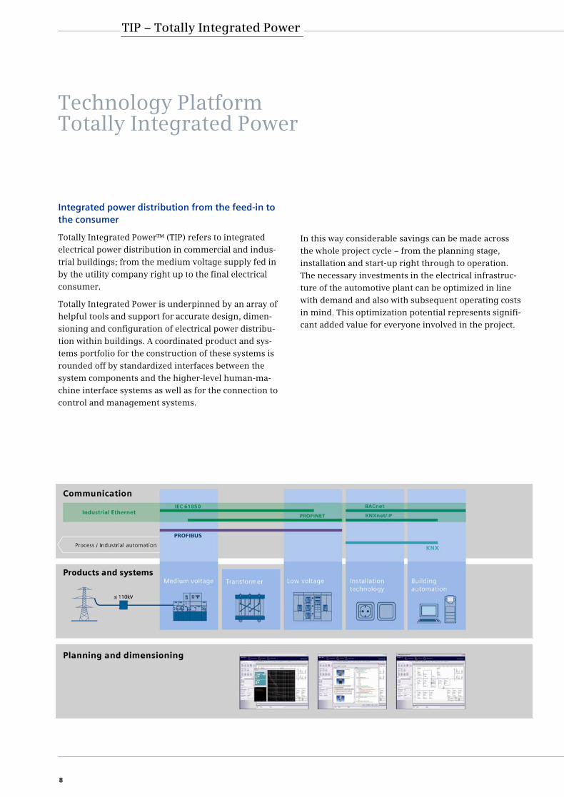
Integrated power distribution from the feed-in to the consumer
Totally Integrated Power™ (TIP) refers to integrated
electrical power distribution in commercial and indus-
trial buildings; from the medium voltage supply fed in by the utility company right up to the final electrical
consumer.
Totally Integrated Power is underpinned by an array of helpful tools and support for accurate design, dimen-
sioning and configuration of electrical power distribu-
tion within buildings. A coordinated product and sys-tems portfolio for the construction of these systems is
rounded off by standardized interfaces between the system components and the higher-level human-ma-
chine interface systems as well as for the connection to control and management systems.
In this way considerable savings can be made across
the whole project cycle – from the planning stage, installation and start-up right through to operation.
The necessary investments in the electrical infrastruc-
ture of the automotive plant can be optimized in line with demand and also with subsequent operating costs
in mind. This optimization potential represents signifi-cant added value for everyone involved in the project.

Totally Integrated Power in the automotive plant
Your advantage of using the Totally Integrated Power technology platform in all project stages
Investments must pay off: for this purpose the dimen-
sioning of the installation is optimized. With the aid of the SINCAL software tool different load flows at the top-
level power system and the supply rings are simulated and components are then optimized accordingly. The
lower-level spur lines are optimized with the SIMARIS
design dimensioning software.
Necessary adaptations of the production lines in case of production conversions are also supported by these
tools (SINCAL, SIMARIS design).
Network calculations in case of modifications result in
reduced investments, because unnecessary reserves are not provided for.
End-to-end type-testing of switchgear and busbars
ensures an unproblematic integration of installation parts especially with regard to the required safety of
persons. The safety proofs were provided by the manu-facturer. The system properties of the integrated port-
folio are known and kept in the software tools so that
integration works smoothly. Many of the protective settings are already available through the system simu-
lation. This speeds up commissioning. Upon customer request, Siemens will take over the complete installa-
tion contract.
In addition, Siemens supports electrical consultants with personal consultations in almost every planning
stage.
9
Low
vol
tage
Low
vol
tage
Automotivemanufacturing H
igh
vol
tage
Med
ium
vol
tage
Transformer unit substation
Protection andEnergy Automation
system
Protection and Energy Automationsystem
Emergency power supply
diesel/UPS
Emergency power supplydiesel/UPS
Low-voltageswitchgear
PowertrainHigh voltage
Medium-voltagesupply
Busway system
Body shopPress shop Paint shop Assemblyshop
PowertrainUtilities
Infeed of po wer supply for production units
Low-voltageswitchgear

10
Power System Structure
Level 1: primary supply
We provide all-in-one solutions for the supply of pro-
duction units from the feed-in to the power consumer, ensuring optimal quality of supply – and thus a reliable
and highly productive process operation.
Tailor-made to the requirements of the respective
plant, we design the primary supply in such a way that all requirements from production are accounted for:
the present electricity demand as much as the fore-casted one plus the system perturbations and load pro-
files of the machinery and equipment in the individual
shops and the required short-circuit strength. All of our systems are designed for service friendliness. This
way you can easily expand your production facilities with our modular and standardized system compo-
nents – while enjoying the freedom of flexibly adjust-ing the power supply to your demand.
Level 2: protection and communication
Another challenge that we meet in conjunction with
power supply is the protection of man and machinery. Within the scope of our solutions we ensure that condi-
tions for disconnection from supply are observed at
any time and that neither man nor machinery will be harmed.
On the one hand, you will protect your facilities against
possible damage by our tailor-made solutions for auto-mating power supply, with the main focus on protec-
tion and power quality, substation automation and
power management, on the other hand, we thus guar-antee a constant quality of the electrical energy and
hence the production processes. In addition, automat-ing power supply ensures that unforeseen events can
be quickly responded to and a possible interruption of supply can be avoided.
Power system structure
Level 3: emergency power supply
What if power supply really fails one day? In this case it
pays that the emergency power supply of the machin-ery and facilities has been tuned to your real demand.
Which areas of production have to be supplied uninter-
ruptedly? Where is a short interruption of power supply
permissible / not permissible? When planning emer-gency power supply in line with these requirements,
we make sure that it is designed in such a way – with uninterruptible power supply units, batteries and
diesel generators – that a blackout has as little effect as possible and your vital processes continue to work.
Our project teams take over all tasks within the frame-work of planning and implementation. This way you do
not only avoid problems caused by more than one interface, since all components are perfectly matched,
the availability of your plant will also rise.
Thanks to our competence and long-standing experi-
ence in numerous projects in the automotive industry, we are capable of meeting all demands on a safe and
totally reliable power supply. At the same time, our experienced teams ensure fast and smooth project
administration for you that also takes into account
your plant engineering manufacturers and OEMs. So that you can produce and supply the market faster.

11
12
The block diagram below describes the power supply scheme in the automotive industry. It shows the sepa-
rate supply of the two main pillars, automobile produc-tion and engine and gearbox production. Power supply
is viewed from the high-voltage level down to the feed-
in for the production machinery.
System configurations are described which are typical for automotive production, such as changeover possi-
bilities at the high and medium-voltage level – which
are necessary to create redundancy – and the typical meshed low-voltage ring provided by a high-current
busbar system that can be coupled.
The diagram points up load-center substations with
their typical panel variants, such as transformer box, low-voltage feed-in panel, busbar meshing panels, in-
line LV HRC fuse-switch-disconnector panels and the choked reactive power compensation unit. As this
switchgear is placed directly within the production ar-ea, very high requirements are imposed on its resis-
tance to accidental arcs.
Siemens provides system solutions for the individual
production steps of an automotive plant (such as body-in-white production, paint shop, assembly etc.). At the
low-voltage side, the corresponding load-center substa-
tions are connected to each other by LD-type busbars (2,500 A to 3,200 A). In order to limit the short-circuit
power to a maximum of 100 kA, suitable coupling switches are built into the busbar route which divide
the supply ring into network sections. If one load-center substation is off – due to a fault or maintenance
– the missing power demand can be covered by anoth-
er network section by closing the corresponding cou-pling switch. These busbars often run at a height of
four to thirteen meters along the walls of the produc-tion halls or in the heading course.
Power supply scheme
Besides their task of building up a meshed-ring system, these high-current busbars (LD busbar system) also
supply large power consumers in the production sec-tions, such as robot groups, main distribution boards
or smaller busbar supply systems via tap boxes. Busbar
systems for medium currents (type BD2: 160 to 1,250 A) supply subdistribution boards or equipment in this
area in a flexible way. Power distribution for the supply of small and ultra-small consumers (16 A to 100 A) is
performed by the busbar system types BD01 and CD-K.
Using busbars which are matched to the requirements of automotive production provides the following ad-
vantages:
► Safe transmission of high currents
► Significant reduction of cabling
► Low fire load
► Fast installation / dismantling
► Unproblematic dismantling when equipment is
moved
► Fast extension possible
► Low planning expense involved compared to cable
installation
► High flexibility when the technology structure is changed
► Tap points close to the consuming equipment
► Transparency of power distribution
► Reduction of subdistribution boards
► Transparency of distribution regarding power
consumers
► Easy extension by standardized tap boxes
► Unproblematic change of power consumers
► Option for metering power consumption in the tap box
Power Supply Scheme in the Automotive Industry

13

14
Presentation of the Portfolio Components Applied
Portfolio
Features Advantages
Modular design Higher availability through easy module replacement
Simple, safe and com-fortable handling
Current transformer princi-ple and pressure-resistant compartmentalization
Selective disconnec-tion in case of inter-nal module faults
Ergonomic design and self-explaining operating logic
Simple and user-friendly handling
Reliable protection of the load-center substations by means of switch-disconnec-tor and fuse combinations (selection and rating in compliance with IEC 62271-105)
High safety for opera-tors and machinery (arc flash energy < 30 kW)
Integrated SIPROTEC protection relays
High flexibility com-bined with the utmost of safety and quality
Draw-out vacuum circuit-breaker
NXAIR medium-voltage switchgear
Features Advantages
Small, compact design Low space requirements, low property cost
High flexibility, easy planning
High availability, low maintenance expense
No interruptions of production
Long service life (> 50 years)
Future-proof investment
Short planning, delivery and installation times
Compact 110-kV GIS 8DN8 switchgear

Features Advantages
End-to-end solution covering all voltage levels
Higher availability thanks to fast identi-fication and rectifica-tion of problems
Future-proof, simple adaptation to customer-specific requirements
Central operator control and monitoring
Higher availability thanks to short response times
Use of standard components
Interfacing to other systems possible, components can be replaced, high safety
Scalable solution for pro-tection, control monitor-ing and automation
Medium-voltage switchgear with integrated SIPROTEC protection technology and SICAMenergy automation technology
NX PLUS C medium-voltage switchgear
Features Advantages
Small, compact dimensions
Low investment in buildings owing to compact dimensions and independence of climatic impact
Maximized reliability of supply
Maintenance free Minimum life cycle cost
Live parts hermetically enclosed, arc fault test
Maximum operator safety
Low risk of fire Reduced operating cost – no additional maintenance cost
Independent of environ-mental and climatic im-pact
15

16
Power supply of a welding line with SIVACON 8PS low-voltage busbar systems and tap boxes
Features Advantages
High-current range 800 A to 6,300 A
Safe transmission of high currents
Significant reduction of cabling
Tap boxes with fuse-switch-disconnectors or circuit-breakers
Low fire load
Arc-fault-tested tap boxes in compliance with IEC 1641 and VDE 60439
Fast installation & dismantling
Unproblematic disman-tling when equipment is moved
Fast extension possible
Reduction of subdistribu-tion boards
Unproblematic change of power consumers
Transparency of distribu-tion regarding power consumers
Easy extension thanks to standardized tap boxes
Lower planning expense involved compared to cable installation
High flexibility when the technology structure is changed
Tap points close to the consuming equipment
Transparency of power distribution
Option for metering power consumption in
the tap box
Low-current range 25 A to 800 A
Portfolio
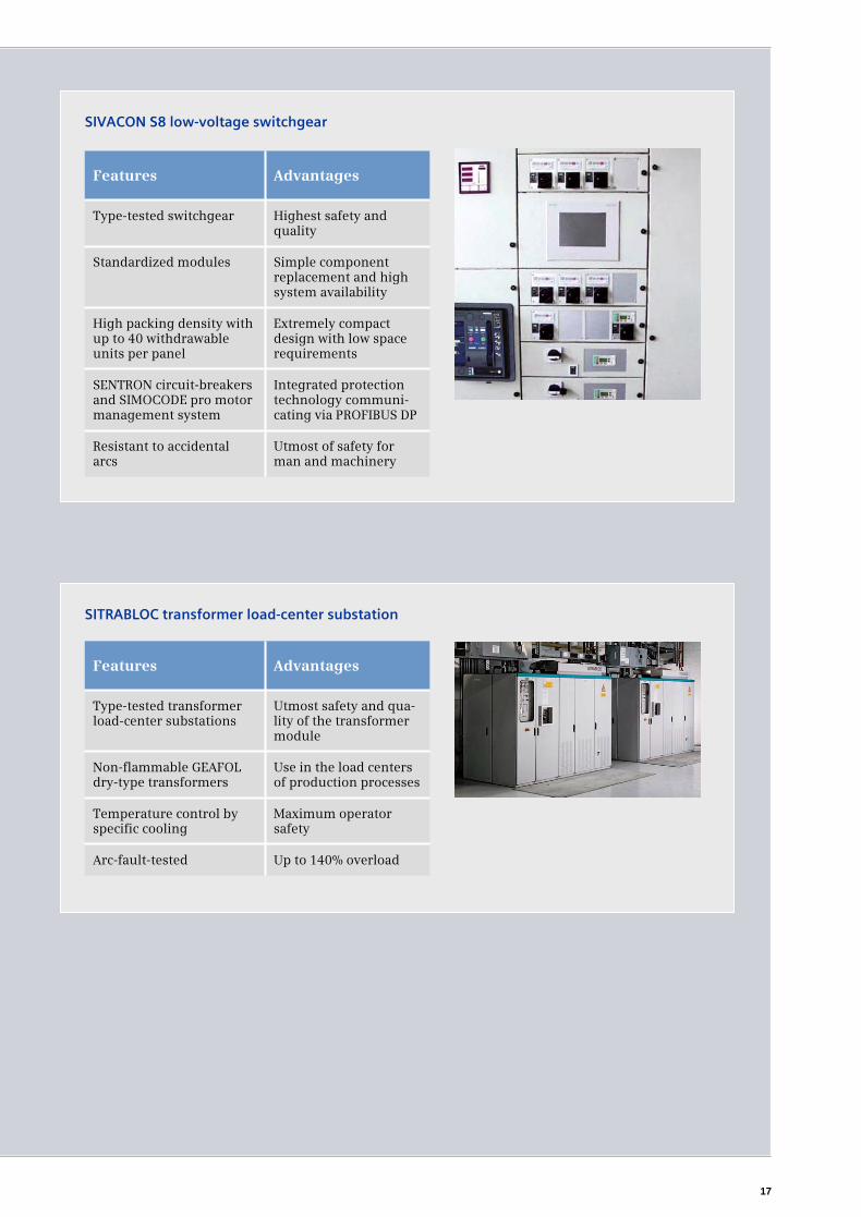
Features Advantages
Type-tested transformer load-center substations
Utmost safety and qua-lity of the transformer module
Use in the load centers of production processes
Temperature control by specific cooling
Maximum operator safety
Arc-fault-tested Up to 140% overload
Non-flammable GEAFOLdry-type transformers
SITRABLOC transformer load-center substation
Features Advantages
Type-tested switchgear Highest safety and quality
Simple component replacement and high system availability
High packing density with up to 40 withdrawable units per panel
Extremely compact design with low space requirements
SENTRON circuit-breakers and SIMOCODE pro motor management system
Integrated protection technology communi-cating via PROFIBUS DP
Resistant to accidental arcs
Utmost of safety for man and machinery
Standardized modules
SIVACON S8 low-voltage switchgear
17
18
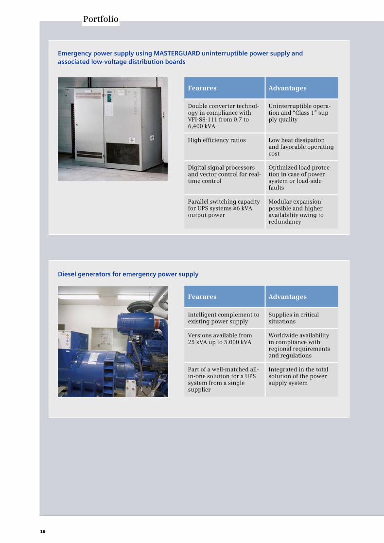
Portfolio
Diesel generators for emergency power supply
Features Advantages
Intelligent complement to existing power supply
Supplies in critical situations
Worldwide availability in compliance with regional requirements and regulations
Part of a well-matched all-in-one solution for a UPS system from a single supplier
Integrated in the total solution of the power supply system
Versions available from 25 kVA up to 5.000 kVA
Features Advantages
Double converter technol-ogy in compliance with VFI-SS-111 from 0.7 to 6,400 kVA
Uninterruptible opera-tion and “Class 1” sup-ply quality
Low heat dissipation and favorable operating cost
Digital signal processors and vector control for real-time control
Optimized load protec-tion in case of power system or load-side faults
Parallel switching capacity for UPS systems ≥6 kVAoutput power
Modular expansion possible and higher availability owing to redundancy
High efficiency ratios
Emergency power supply using MASTERGUARD uninterruptible power supply and associated low-voltage distribution boards

Planning electrical power distribution for commercial
and industrial buildings has never been as complex as
it is today. The planning process demands a great deal of specialized knowledge and experience. With an expe-
rienced partner at their side, electrical engineering consultants can implement their conceptual expertise
more quickly and easily and concentrate on the impor-
tant things. SIMARIS design and technical manuals from Siemens offer comprehensive support, from the
preliminary planning stage right through to implemen-tation planning.
SIMARIS design
The SIMARIS design dimensioning software supports
our complete, integrated and high-quality portfolio from medium voltage technology through to wall out-
lets. The user-friendly TÜV-certified tool also generates the necessary selectivity verification, for instance for
emergency power supply systems. It also lightens the
load enormously in routine work such as implement-ing changes and considering variants.
Application manuals
Siemens application manuals offer electrical engineer-
ing consultants a wide knowledge and information base to draw on when designing electrical power dis-
tribution systems.
There are three volumes, available from regional Siemens contact partners (www.siemens.com/tip/
support):
► The application manual “Basic Data and Preliminary
Planning of Power Distribution Systems” provides electrical designers with in-depth information to
support them in their work during these two
phases.
► The application manual “Draft Planning of Power Distribution Systems” provides useful information
on this project phase.
► The application manual “Planning a High-Rise Building” documents concrete applications of the
power distribution products and systems using the
example of an office tower.
Professional Planning Aids
Planning aids for power distribution
19

The information provided in this brochure contains merely general descriptions or characteristics of performance which in actual case of use do not always apply as described or which may change as a result of further development of the products. An obligation to provide the respective characteristics shall only exist if expressly agreed in the terms of contract.
All product designations may be trademarks or product namesof Siemens AG or supplier companies whose use by third parties for their own purposes could violate the rights of the owners.
Siemens AGIndustry SectorLow-Voltage Controls and DistributionP.O. Box 48 4890327 NUREMBERGGERMANY
www.siemens.com/tipSubject to change without prior notice 01/09 © Siemens AG 2009
Further information
You can find more information onTotally Integrated Power on the Internet at:www.siemens.com/tip