Embed Size (px)
Citation preview

Innovative Phased Array Synthetic Aperture Radar
System on Chip for Satellite Applications
Presented by ZHENG Yuanjin
School of EEE
Singapore Space Symposium 2015
Sep. 30, 2015

SAR on Satellite
2
• Optical Quality Images at Microwave Frequencies
• Active System – Day and Night Imaging
• Adverse Weather
• Long Stand-off Ability (fine resolution imaging independent of range)
• Coherent Imaging–Interferometric SAR
• Penetration of Materials and Particulates (frequency dependent)
• Detection of Ground Moving Targets
Micro
Satellite
SAR
Module
Circuit
Board
It remains great challenge to payload the mini
SAR in MicroSatellite
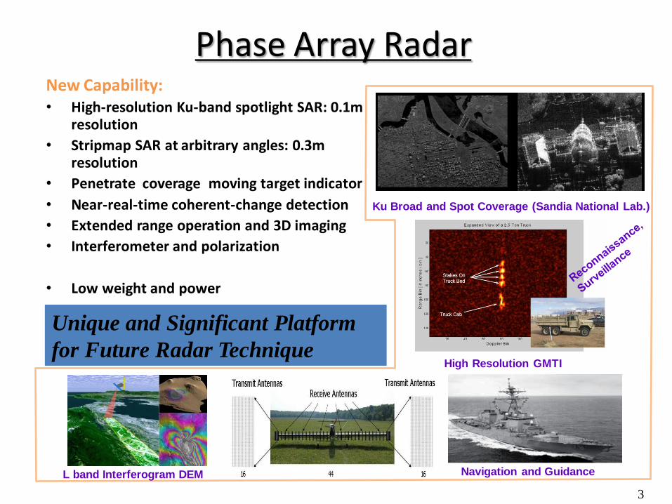
Phase Array Radar New Capability: • High-resolution Ku-band spotlight SAR: 0.1m
resolution
• Stripmap SAR at arbitrary angles: 0.3m resolution
• Penetrate coverage moving target indicator
• Near-real-time coherent-change detection
• Extended range operation and 3D imaging
• Interferometer and polarization
• Low weight and power
3
Ku Broad and Spot Coverage (Sandia National Lab.)
High Resolution GMTI
Unique and Significant Platform
for Future Radar Technique
L band Interferogram DEM
Navigation and Guidance

First Generation Radar Chip Transceiver
4
PA
Balun
Coupler
Driven PA
Chirp Synthesizer
40MHz Reference
Receiver Front-End
LNA VGA BPF ADC 10 bits -30dBm IP1dB
12dBm 20dBm
Differential Outputs
PC104
Chip Transceiver
Chip Photo Chip Testing PCB
BPF

Radar Chip-α2
2
Second Generation of Chip Transceiver
Radar Chip-α2: Improved version of Chip-α1, tapeout on Jan.
2015. Chip came back on Late May
Radar Chip-β2: A compact version for phase array and
commercialization, tapeout on Jan. 2015. Chip came back on Late May.
Radar Chip-β1
2cm
1.8cm
8.5 cm
4.5 cm
11.5 cm
7 cm
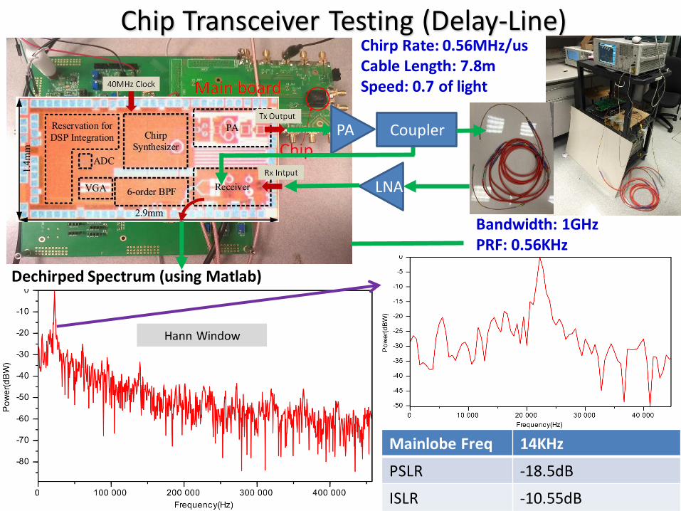
Chip Transceiver Testing (Delay-Line) Chirp Rate: 0.56MHz/us Cable Length: 7.8m Speed: 0.7 of light
PA
LNA
Coupler
Bandwidth: 1GHz PRF: 0.56KHz
Hann Window
Dechirped Spectrum (using Matlab)
Mainlobe Freq 14KHz
PSLR -18.5dB
ISLR -10.55dB

Chip Transceiver Testing (Antenna Field Testing)
Coupler
PCB Receiver
Scene of the Dechirping testing
PA
To spectrum analyzer
3dBm 15dBm
11dBm
6dBm
12dBi
12dBi
1.5m
29dB gain
0.2m cable 7

Chip Transceiver Testing (Ranging Performance)
11.46KHz
Dechirped Spectrum (1GHz BW 1ms of sawtooth)
Testing Setup Parameters
Bandwidth 1GHz (Sawtooth)
PRF 1KHz
Centre Freq. 16GHz
RF Cable 0.2m
Distance R 1.5m
3 8
9 3
2
11.46 10 3 100.2
2 1 10 1 10
1.519
bcable
f cR L
BW PRF
m
Distance Measured:
8

Chip Transceiver Testing (2 Targets Ranging)
Coupler
PCB Receiver
Scene of the Dechirping testing
PA
To spectrum analyzer
3dBm 15dBm
11dBm
6dBm
12dBi
12dBi
29dB gain
1st Reflector Small RCS
and not pointed by antennas
2nd Reflector Large RCS
Chip testing board
Antennas
1st Reflector
2nd Reflector
~13dB
Chirp Rate: 0.56MHz/us 1GHz BW, 0.56KHz PRF
9

Miniaturized Phase Array SAR Sensor System
10
We are targeted miniaturized, low power, low cost SAR sensor for Micro-Satellite applications
Reduction of Size/Weight/Power/Cost (X 10-50) Performance improvement (X5)Bulky System
Modular System
Integrated Phase Array TRX IC ChipDigital Proc. System RF Front-end Modules
Highly integrated IC chips with hybrid microwave modules will be the ultimate solution for miniaturizing radar systems
3D Packaging
Integrated Transceiver
Chip
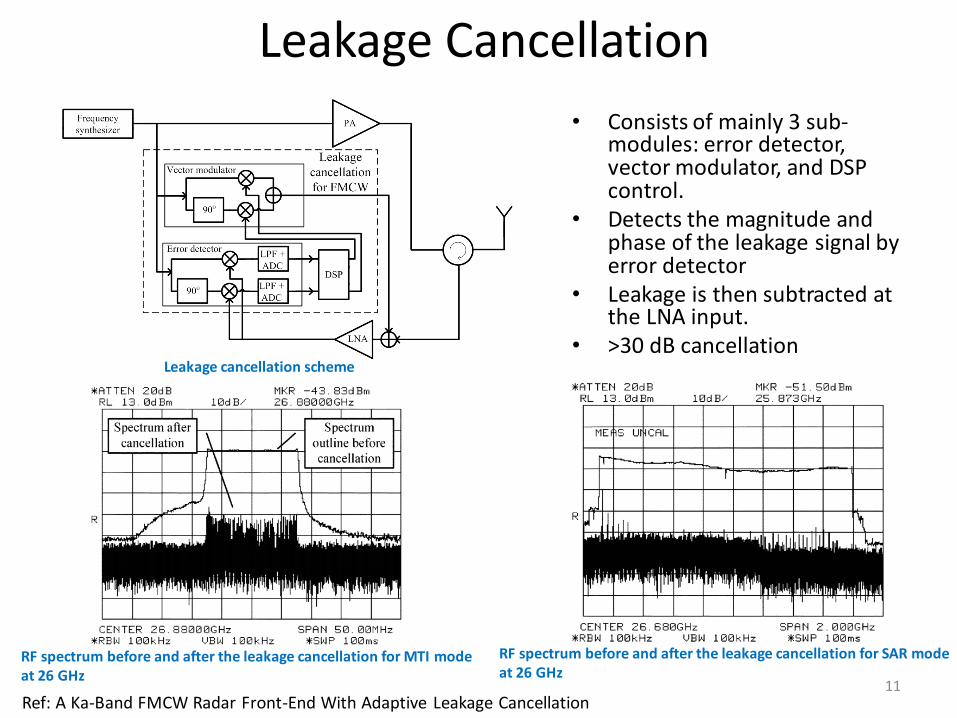
Leakage Cancellation
• Consists of mainly 3 sub-modules: error detector, vector modulator, and DSP control.
• Detects the magnitude and phase of the leakage signal by error detector
• Leakage is then subtracted at the LNA input.
• >30 dB cancellation
Ref: A Ka-Band FMCW Radar Front-End With Adaptive Leakage Cancellation
RF spectrum before and after the leakage cancellation for MTI mode at 26 GHz
RF spectrum before and after the leakage cancellation for SAR mode at 26 GHz
Leakage cancellation scheme
11

Fast Chirp : Gear shift and two point modulation • Gear-shift technique
– PLL close loop transfer function is dynamically adjusted
– < 1μs frequency switch
• 2-point modulation – Low pass input at FCW – High pass input at DCO input – PLL loop bandwidth is effectively extended to
infinite. – Enable sweeping over a large bandwidth in
short sweep cycles. – ~ 200 μs fast chirp
Ref: A 4-GHz All Digital PLL With Low-Power TDC and Phase-Error Compensation
Measured frequency characteristics of FMCW signal for (a) Tmod=1.68ms, BW=1 GHz; (b) Tmod=0.42ms, BW=1 GHz Frequency settling
DPLL with gear shift and 2-point modulation
12

Phased Array Transceiver • X band FMCW phased array • 8 channels • Signal generated from DDFS • Phase resolution 0.6 degree • Phase angle: ± 30 degree
Ref: A Frequency-Modulated Continuous Wave Phased Array Marine Radar System Based on Smart Antenna Technology
System block diagram of the beamformer consisting of 8 FMCW transmitters array Measured radiation pattern with beam-forming
antenna
13