Embed Size (px)
Citation preview

INNOVATIVE PHASE CHANGE THERMAL ENERGY STORAGE
SOLUTION FOR BASELOAD POWER
DOE SunShot CSP Review
April 24, 2013
2
Project Title: Innovative Phase Change Thermal Energy Storage Solution for Baseload Power
Awardee: Infinia Corporation
Principal Investigator: Songgang Qiu
Presenter: Maury White
Subcontractor: Temple University
Project Period: 06/01/10 – 04/30/13 (Phase 1)
PROJECT OVERVIEW
3
• Background & Description
• Objectives and Goals
• Infinia Baseload Technology Concept
• Advantages over Alternatives and Energy Comparison with Molten Salt TES
• Implementation Options
• Subscale Module Development and Test Results
• Lab-Scale Module Development and Test Results
• Solar Receiver to TES Heat Transport System
• System Preliminary Design
• LCOE and Capacity Factor Analysis
• Conclusions & Path Forward
PRESENTATION OUTLINE

4
BACKGROUND & DESCRIPTION
The baseline TES approach for most Trough and Central Receiver Systems uses sensible heat capacity of molten salt
This necessitates power converter operation over a range of temperatures which reduces integrated efficiency
Freezing of molten salt needs to be avoided and a heat transfer fluid must be pumped throughout the system
Phase Change Materials (PCM) provide a large increase in energy storage density by using latent heat of fusion for TES
An Infinia heat pipe PCM TES was described earlier – this project maintains hermetic sealing but avoids heat pipes within the TES and is scalable to a high capacity

5
OBJECTIVES & GOALS
Overall Objective: To develop and validate an innovative, scalable
phase change salt thermal energy storage (TES) system that can
interface with Infinia’s free-piston Stirling engines or other power
converters.
Project Innovation: The phase change material latent heat energy
storage offers high energy density as compared with sensible heat
storage systems, while a liquid metal pool boiler heat transport system
that is integral with the TES salt avoids heat pipes and costly pumping
systems.
6
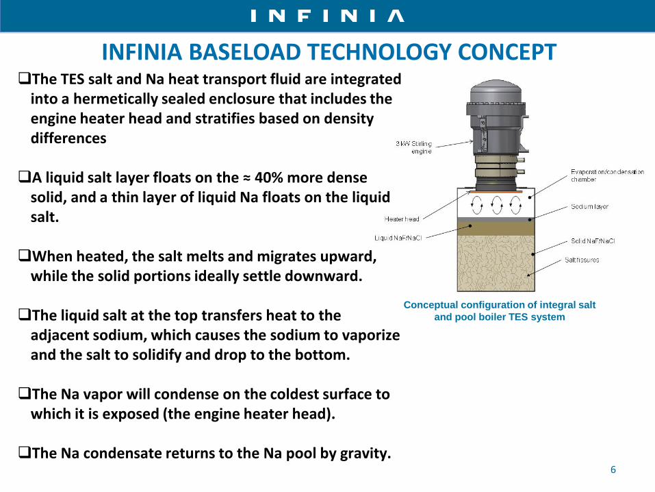
Conceptual configuration of integral salt
and pool boiler TES system
The TES salt and Na heat transport fluid are integrated into a hermetically sealed enclosure that includes the engine heater head and stratifies based on density differences A liquid salt layer floats on the ≈ 40% more dense
solid, and a thin layer of liquid Na floats on the liquid salt. When heated, the salt melts and migrates upward,
while the solid portions ideally settle downward. The liquid salt at the top transfers heat to the
adjacent sodium, which causes the sodium to vaporize and the salt to solidify and drop to the bottom. The Na vapor will condense on the coldest surface to
which it is exposed (the engine heater head). The Na condensate returns to the Na pool by gravity.
INFINIA BASELOAD TECHNOLOGY CONCEPT

• Integral TES/pool boiler with latent heat storage can adapt to any type of power conversion unit from a few kW to tens or hundreds of MW
• Phase change latent heat TES has very high energy density
• Engine extracts heat near melt point to always operate at selected optimum temperature
• Eliminates the need for heat pipes to reduce cost and complexity • Pure or eutectic salts can be selected for virtually any melt temperature
from 300 C to 1300 C • NaF/NaCl eutectic selected for very low cost with excellent 680 C melt
point • Hermetically sealed salt/liquid metal module is maintenance free • No high temperature pumps or swivel joints needed • Salt freezing is a non-issue that occurs during normal operation • Earlier Infinia small LiF/NaF test module cycled through three 652°C
melt/freeze cycles per day for over 4 years with negligible impact on stainless steel containment vessel
7

8
ALTERNATIVE SALT STORAGE CAPACITY BY WEIGHT (TROUGH SALT IN BLACK ★ )
250 300 350 400 450 500 550 600 650 700 7500
400
800
1200
1600
2000
Temperature [C]
En
erg
ysto
red
[W-h
r/kg
] LiHLiH
LiFNaFMgF2LiFNaFMgF2
NaFNaClNaFNaCl
NaNO3 KNO3NaNO3 KNO3
Peak Available
MOLTEN AND PHASE CHANGE SALT ENERGY STORAGE BY WEIGHT

9
ALTERNATIVE SALT STORAGE CAPACITY BY VOLUME (TROUGH SALT IN BLACK ★)
250 300 350 400 450 500 550 600 650 700 7500
300
600
900
1200
1500
LiHLiH
En
erg
ysto
red
[W-h
r/L
]
Temperature [C]
LiFNaFMgF2LiFNaFMgF2
NaFNaClNaFNaCl
NaNO3 KNO3NaNO3 KNO3
Peak Available
MOLTEN AND PHASE CHANGE SALT ENERGY STORAGE BY VOLUME

10
• The selected TES system design approach is to mount the
module and engine behind the dish as a dish forward
counterbalance
• A pumped loop heat pipe transports heat from the solar
receiver to the TES module as with the Sandia concept
• The engine must be mounted above the pool boiler and
avoid direct contact between salt and the heater head
• The TES/engine assembly must be able to rotate ±45°
from vertical to cover all solar tracking positions
• 12 hour TES is feasible for this dish configuration
• An alternative future potential TES configuration is to
utilize a central receiver with a directly heated integral
TES on a tower with various power converter options Morning/Evening
Position Midday Position
30kW Tower Configuration
Concept
Infinia 3kW Dish Mounted Approach
Sandia 25 kW Dish Mounted Heat Pipe TES Concept
BASELOAD TES IMPLEMENTATION OPTIONS

Three generations of subscale modules were developed to:
• Prove the basic physics before committing to lab-scale unit integrated with a 3 kW engine
• Gain experience processing PCM salt and sodium
• Gen 1 and Gen 2 had calorimeter, processing and instrumentation issues that limited results
• The major issue identified was the tendency of the liquid salt to form a surface crust without sinking
11
Generation1 Subscale Module Generation 2 Subscale Module
Generation 3 Subscale Module
12
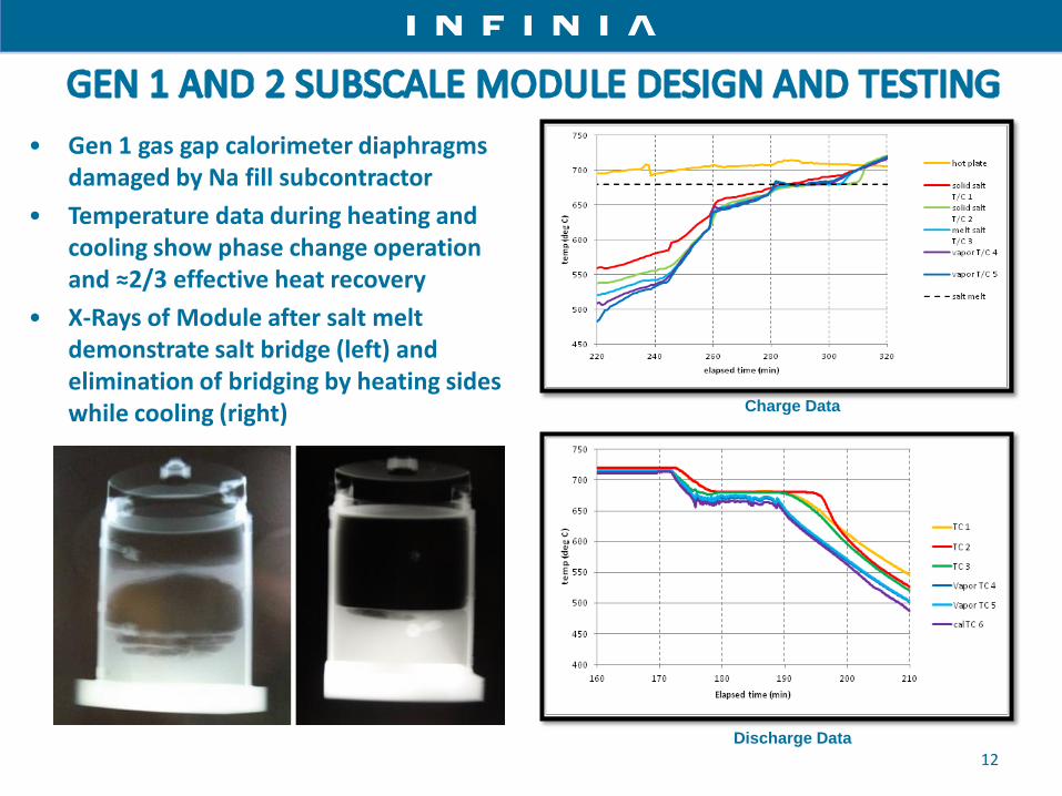
Charge Data
Discharge Data
• Gen 1 gas gap calorimeter diaphragms damaged by Na fill subcontractor
• Temperature data during heating and cooling show phase change operation and ≈2/3 effective heat recovery
• X-Rays of Module after salt melt demonstrate salt bridge (left) and elimination of bridging by heating sides while cooling (right)

13
The overall objective of Gen 3 was to validate functional aspects of the Baseload concept in a scale and configuration closer to the lab-scale one-hour demonstrator.
Improvements relative to Gen 1 and Gen 2:
Eliminated thermal short circuit around the calorimeter
Made input heat flux more representative of actual solar conditions
Reduced excessive insulation losses Introduced the effect of tapering the
vessel side walls to provide easier liquid salt flow to the surface during heating
Gen 3 Subscale Module Gen 3 Module Susceptor
Heating
Completed Gen 3 Modules

14
• Photo shows unit ready for testing with some insulation removed
• X-ray shows series of salt bridges formed during heat extraction
• Latent heat extraction is consistently about 2/3 that of the salt’s ideal potential

15 1 Hour Laboratory Module
• Fabricated from 304 stainless steel
• Standard elliptical end cap modified for welding to heater head and standard 74 cm (29 in.)
diameter hemispherical dome
• Thermosiphons incorporated internally to improve internal heat transfer function
• Charged with 170 kg NaF/NaCl eutectic salt and 6.5 kg sodium for the pool boiler
• Preliminary testing conducted December 2012
TES MODULE LAB-SCALE DEMONSTRATION HARDWARE

16
LAB-SCALE UNIT THERMOCOUPLE LOCATION IDENTIFIER

• Sodium pool boiler heat transport to engine provided up to 3 kW electric output
• 3.9 kWh of engine net energy output was achieved from stored TES
• This was more than original objective but only about half the actual potential
• Salt crusting during heat extraction is the primary residual issue
• The thermosiphon designed to reduce or eliminate crusting was destroyed during fabrication so could not be evaluated
17

18
• A high-level HTS trade study was conducted
• Two basic configurations were evaluated for both dish and tower options Ground-mounted engine/TES system physically de-coupled from the heat (solar) receiver
Engine/TES system mounted on dish or tower
• HTS using pumped loops with either molten salts or liquid metals were considered
• Stirling engines (without TES) have demonstrated improved performance when heated by liquid metal pumped loops
• A pumped loop sodium heat pipe is fundamentally different with heat transport by sodium vaporization/condensation and pumping requirements about two orders of magnitude lower
SOLAR RECEIVER/HEAT TRANSPORT SYSTEM (HTS)
• Conclusions • Existing mechanical pumps for salts or liquid metal heat transport fluids are generally limited
to about 500 to 550°C and require regular maintenance • Electromagnetic pumps can go to higher temperatures but have low efficiency • High costs for either system make them impractical for primary HTS pumping with systems
below several tens of kW • A pumped loop sodium heat pipe between the solar receiver and TES/engine module behind
the dish is the most practical option for a 3 kW system

19
With and without intermediate HX identified
Pumped System with
Intermediate HX
Pumped System without Intermediate HX;
Closed Configuration
Similar pumped looped systems
under test at NASA
2kW Stirling Engine Test Set-Up;
Liquid Metal (NaK) HTS Thermal Input
Hybrid System Employing a Single Heat
Transfer Fluid Concept
Hybrid Concept
Alternative Pump Configuration Concept Identified
Bulk Circulating Pump Configuration Bubble-Lift Pump
HEAT TRANSPORT SYSTEM (HTS) CONCEPT EVALUATIONS
20
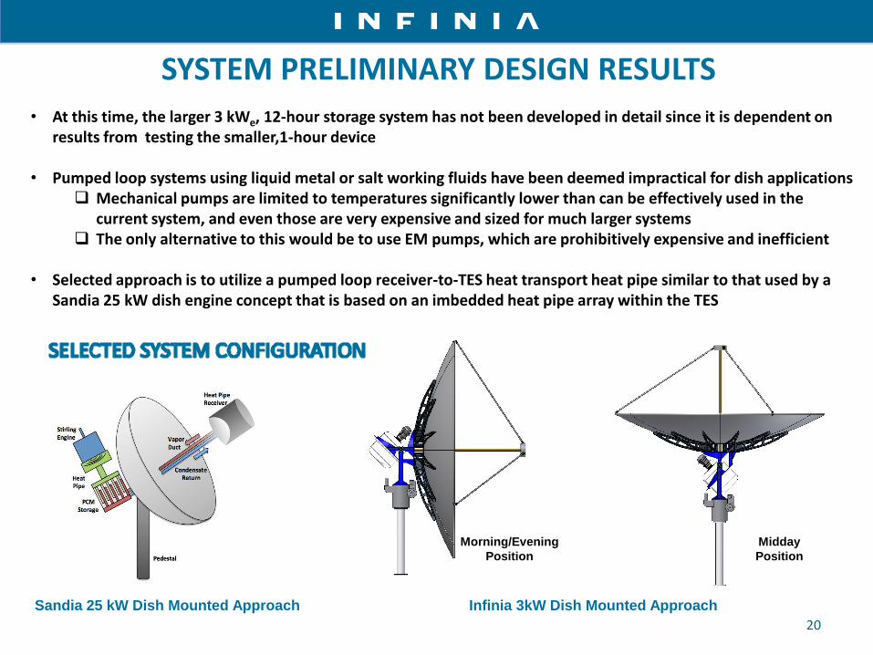
• At this time, the larger 3 kWe, 12-hour storage system has not been developed in detail since it is dependent on results from testing the smaller,1-hour device
• Pumped loop systems using liquid metal or salt working fluids have been deemed impractical for dish applications Mechanical pumps are limited to temperatures significantly lower than can be effectively used in the
current system, and even those are very expensive and sized for much larger systems The only alternative to this would be to use EM pumps, which are prohibitively expensive and inefficient
• Selected approach is to utilize a pumped loop receiver-to-TES heat transport heat pipe similar to that used by a Sandia 25 kW dish engine concept that is based on an imbedded heat pipe array within the TES
Sandia 25 kW Dish Mounted Approach
Infinia 3kW Dish Mounted Approach
Morning/Evening
Position
Midday
Position
SYSTEM PRELIMINARY DESIGN RESULTS

21
An LCOE comparison of various technologies using DOE CSP financial assumptions showed the Infinia PowerDishTM technology provides one of the lowest LCOE values. Inclusion of TES with the PowerDishTM reduces initial costs by 20%, after which a 3% cost down with a 2% performance increase is deduced. LCOE analysis for the PowerDishTM used 4 hours of TES. Capacity factor analysis for a mini power tower showed a 10% LCOE reduction as capacity increased from 6 hours of TES to 12 hours.
LCOE AND CAPACITY FACTOR ANALYSIS

22
CONCLUSIONS & PATH FORWARD
Phase change salt TES offers dramatic advantages over alternative approaches
Most elements of Infinia’s simple and elegant integral TES and pool boiler concept function very well
The salt crusting during heat extraction remains the primary unresolved issue
Outside funding support is needed to continue development
More testing of existing lab-scale TES module is needed to fully characterize operation
Further evaluation of salt physical and thermophysical processes is needed to understand and mitigate crusting problem
Thermomechanical mitigation of crusting using thermosiphons or other means needs to be evaluated – a method for retrofitting the damaged thermosiphon has been identified and should be implemented

23
US Headquarters
300 West 12th Street
Ogden, UT 84404
www.infiniacorp.com
Thank you