Embed Size (px)
Citation preview

Innovative Cost-Effective Control Device for Wastewater VOC Emissions
(As Required by NESHAPs [BWON, HON, MON, MACT] and Other Regulations)
Dr. Carl E. Adams, Jr., PE, Senior Author1 *
Dr. Lial F. Tischler2
Andrew W. Edwards, PE3
1 ENVIRON International Corporation, Nashville, Tennessee2 Tischler/Kocurek, Austin, Texas3 ENVIRON International Corporation, Houston, Texas

VOC Emissions Regulatory Overview
USEPA NESHAP and State RACT typically require:
− Control of Hazardous Air Pollutants (HAP) or VOC off-gases from
storage vessels & sumps
process vents
wastewater equipment
− ≥ 95% removal of VOC or HAP (98% benzene removal for BWON)
Traditionally accepted Control Technologies Traditionally accepted Control Technologies
− Adsorption (e.g., carbon adsorbers)
− Enclosed combustion (oxidizers & fuel gas systems)
− Scrubbers
− Flares

Vapor Phase Adsorption: Granular Activated Carbon
Thermal Oxidizers: Flare or Gaseous Incinerator
Figure 1. Typical Acceptable Control Devices
ThermalOxidizers
Granular Activated Carbon Canisters

Alternative Control Technology Option Can Substantially Lower Cost
Traditional control disadvantages include
− High capital cost
− High operation and maintenance costs• Carbon regeneration/replacement
• Fuel consumption
• Nitrogen loss• Nitrogen loss
− Operational complexity
Regulations specifically allow for “alternative control technology”
− Must demonstrate equal or better emission reduction
− Must obtain approval of Administrative Authority (i.e., EPA and/or State); e.g., BWON requires demonstration of 98% benzene removal
− Must follow USEPA protocols for approval
What is VOC BioTreat?
VOC BioTreat is the process of qualifying an Alternative Control Device, other than Activated Carbon or Thermal Oxidation, for the biodestruction of regulated biodegradable VOC emissions.
The Alternative Control Device is cost-effectively an existing activated sludge process with emission sources in proximity to WWTP.

VOC BioTreat - an Approved Alternative Control Device
The authors have developed new and improved demonstration methods (protocols):
− Bench-scale BOX Test and Core Column Simulation full-scale confirmation
− Provides more realistic and reliable VOC biodegradation rates than the EPA default methodsthe EPA default methods
− Allows for EPA and/or State approval of VOC BioTreat as equivalent treatment technology
Has been approved as BWON alternative control device
− USEPA has accepted improved BOX Test and Full Scale confirmation methods
− State of Louisiana has issued written approval of approach and Alternative Control status
− All states are expected to “sign off” on USEPA-approved protocols

Figure 2. Basic Overview of Alternative Control Device for a Refinery

A Cost-Effective Solution for the Biodestruction of VOC Emissions
Incorporates protocols presented herein to demonstrate an Alternative Control Device
Confirms the use of existing biological wastewater treatment facilities.
Follows exact EPA requirements and protocols for approval

A Cost-effective Solution for the Biodestruction of VOC Emissions
Conclusively demonstrates co-treatment of gaseous emissions or VOCs and aqueous soluble organics in existing wastewater treatment facilities.
Using these protocols, most activated sludge biotreatment systems can be qualified as an Alternative Control Device to treat biodegradable VOCs.biodegradable VOCs.
It is transferable to other VOC/HAP and other regulations.

Approach: High-Level Assessment
Existing WWTP amenable to the technology?
− Diffused aeration system
− Deep tanks
− Existing blowers have adequate air flow treatment capacity (modification may be necessary)
VOC emission sources appropriate for technology?
− Compounds relatively biodegradable− Compounds relatively biodegradable
− Compounds have sufficient solubility (relatively low Henry’s Law constants)
− VOC air volume compatible with WWTP diffused air treatment capacity
Favorable economics?
− Reasonable proximity of VOC sources to WWTP
− Current system O&M costs
− Minimal modifications required to adapt WWTP to technology

VOC BioTreat - The Process
Step 1: High Level Feasibility Evaluation
Step 2: Develop preliminary facility-specific model with assumed biodegradation rate to gauge benzene removal performance requirements and obtain initial Agency concurrence for approach
Step 3: Conduct BOX testing to determine site-specific VOC biodegradation rate and maximize VOC BioTreat effectivenessbiodegradation rate and maximize VOC BioTreat effectiveness
Step 4: Conduct Core Column Simulation Full-scale confirmation testing
Step 5: Obtain final Agency approval of Alternative Control Device
Step 6: Prepare detailed engineering plan and implement Alternative Control Device solution
Step 1 & 2 must be concluded and favorable before proceeding with the rest of the program.

TOXCHEM+ Is Model of Choice TOXCHEM+ is used on all VOC BioTreat projects
TOXCHEM+ Proprietary model - Hydromantis, Inc.
Approved by EPA for wastewater unit emissions estimates (V.4 is current)
Must input and use EPA (WATER9) physical and chemical properties for VOCs being modeled (TOXCHEM+ has its own database but allows entry of modified chemical properties)allows entry of modified chemical properties)
Advantages− Easy to use interface
− Assumes non-equilibrium for rising air bubbles
− Allows modeling of contaminated gases
Disadvantages− Poor simulation of surface aerator emissions
− Must input WATER9 chemical characteristics to use for inventories, compliance
− May incorporate a questionable KG / KL

Case History
Marathon Petroleum Company Garyville Refinery (MPC)
Garyville, Louisiana

Figure 3. Current/Proposed Benzene Control Devices
MPC requested that ENVIRON develop the protocols to qualify the existing activated sludge system (AIS) as an Alternative Control Device.

Table 1. Economic Impacts for VOC Control Devices MPC-Garyville Refinery WWTP
Process Technology
Cost-Effective Impact
Capital cost ($) Annual Operating Cost ($)
Thermal Oxidizer 600,000 340,000
Granular Activated Carbon (6 carbon canisters on each of two API separators,22 change-outs/yr per API) + Maintenance of a N2 blanket
240,000 500,000
Biological (piping, fans and connection to blowers)
600,000 Minimal
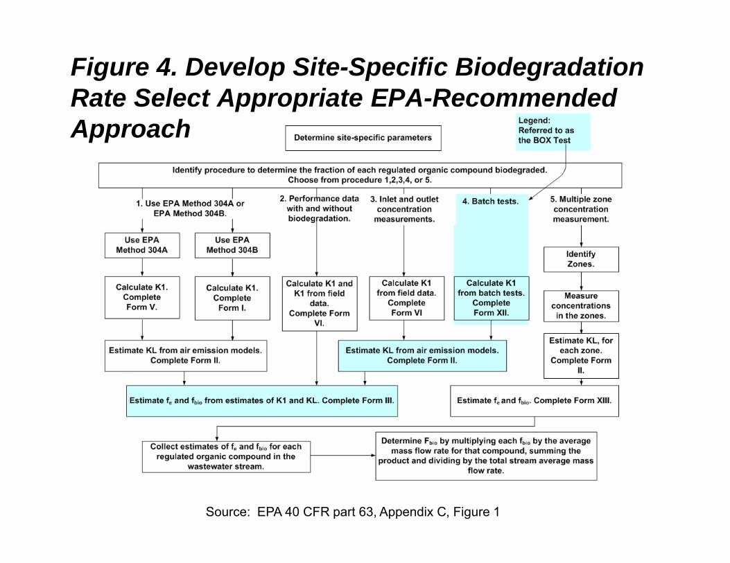
Figure 4. Develop Site-Specific Biodegradation Rate Select Appropriate EPA-Recommended Approach
Source: EPA 40 CFR part 63, Appendix C, Figure 1

Major Variables
Benzene Biodegradation Rate
– Table 2 represents various experimentally-determined biorates from API and ENVIRON databases
Other Significant Variables
Air Distribution in Zones
Depth of BioReactor
Aeration Tank Surface Area
Temperature
Inputs to Site-Specific Model
ENVIRON databases
Air Flow
Biomass Concentrations
Potential Benzene Injection Locations into AIS
Benzene Loadings
– See Figure 5.
Temperature
Hydraulic Flow Rate & COD Loading

Figure 5. Reliable Data on Benzene CriticalBenzene Mass Balance for MPC Garyville

Table 2. Various Benzene Biodegradation Rates for BWON Modeling
Benzene Biodegradation Rates – Experimental Values
Refinery Test Type Date Runs
K1 (L/g VSS-hr) @ 20 oC
Average for Multiple Runs
Value Selected for
Model Evaluation
API-A BOX Nov-06 2 48.9 -----
API-A Method304A
Nov-06 1 120.1 84.5
API -B BOX Oct-97 1 79.1 79.1
API-C BOX Oct-97 2 78.4 78.4
API-D EKR Jul-96 4 17.3 17.3
API-D BOX Jul-96 5 122 -----
API-E BOX Sept-94 5 122 -----
Data referred to as API is from Table 5 of the API/NPRA comments to EPA
API-E BOX Nov-94 2 31 -----
API-E BOX Dec-94 6 199 -----
API-E BOX Apr-95 5 199 -----
API-E BOX Apr-95 7 172
API-E BOX Jun-95 4 206 185.5
API-F BOX Jul-95 3 4.4 4.4
API-G Mar-00 3 64 64
ENVIRON- 1 BOX Jul-09 2 23.4 23.4
ENVIRON- 2 BOX Mar-11 1 19.7 19.7
ENVIRON- 3 BOX Aug-11 1 10.8 10.8
ENVIRON-4 BOX Aug-11 1 6.4 6.4
API Water 9 Default Rate 1.4
comments to EPA dated December 28, 2007.

Figure 16. Benzene Removal with Preliminarily Assumed Rates

Figure 7. Actual Site-Specifc Benzene BioRate BOX Test Apparatus as typically used
High quantity of off-gas per bioreactor volume (increases potential for air stripping)
Bioreactor approximately 2 L Volume

Figure 8. BOX Test Apparatus Recommended and Designed by ENVIRON Approved by USEPA & State of Louisiana
Continuous gas sample collected for on-line
benzene analysis
Deeper liquid depth and larger bioreactor diameter, along with
recycle capability, (minimizes potential
Bioreactor approximately 22.2 L Volume
(minimizes potential for non-representative
air stripping)Considered more
realistic of full-scale conditions

Size– 15.4“ (39 cm) long, 10.6“
(27 cm) wide, 5.9“ (15 cm) high
Display– 128 x 64 element graphical
LCD with backlighting
Serial Output
Figure 9. Specifics of the on-line Photovac Voyager GC
Serial Output– RS-232, for connection to
Windows™ based PC and communication to SiteChartsoftware
Detectors– Photoionization detector
with quick-change electrodeless discharge
– UV lamp, 10.6 eV(standard); Electron Capture Detector (optional)
Alarm Output– Internal audio - 85 decibels– Alarm LED
Operating Temperature Range– 41°F to 105°F (5°C to 40°C)
Operating Humidity– 0-100% Relative Humidity (non-condensing)

Figure 10. Setup of the BOX Test
BOX Test Column (without aeration)
Air Supply Tank(Supplies BOX Test
Column & GC)
Voyager Photovac On-
Line Photo-ionization GC
Sample Syringes
Fine-Bubble Air Diffuser
(Off)

Figure 11. Comparative Results of Benzene Stripping with and without Biomass
150
200
250
BE
NZ
EN
E I
N O
FF
-GA
S E
MIS
SIO
NS
(p
pm
v)
Off-Gas in Head SpaceWITHOUT BIOMASS ~2 mg/L Benzene added to filtered effluentpH = 7.8Dissolved Oxygen = 10.6 mg/L
Temperature = 21.0 oCOff-Gas in Head SpaceWITH BIOMASS
0
50
100
150
0 50 100 150 200 250 300 350 400 450
TIME (min)
BE
NZ
EN
E I
N O
FF
-GA
S E
MIS
SIO
NS
(p
pm
v)
Temperature = 21.0 CWITH BIOMASS ~2 mg/L Benzene added to biomassMLVSS concentration of 800 mg/LAir flow through diffuser = 1 L/min pH = 7.3Dissolved Oxygen = 7.5 mg/L
Temperature = 26.0 oC

Figure 12. Smoothed Data Fit as per USEPA Criteria for Fbio Calculation

Development of Preliminary Site-SpecificBenzene Control Model
The site-specific biodegradation rate, corrected to 20 oC, is
- 22.6 L / g VSS-hr @ 20 oC at Marathon-Garyville
- USEPAA Default rate is 1.4 L Benzene / g VSS-hr @ 20 oC
The Toxchem+ model will adjust the rate to the selected temperature for full-scale operating conditions.

Figure 13. Benzene Removal with Preliminarily Assumed Rates vs. Actual Site-Specific Rate (Corrected to 20 oC)

Figure 14. Full-Scale Confirmation Flux Chamber: Less Desirable Option

Figure 15. Full-Scale Confirmation
Performance Validation of Full-Scale System Using VOC BioTreat Column Protocols

Figure 16. Full-Scale Confirmation

Figure 17. Full-Scale Confirmation

Table 3. Full-Scale Confirmation ResultsBenzene Analytical Results of Full-Scale Confirmation
Run #
Benzene Concentration, ppbv
Benzene Biodestruction
(%)
Percent of Design
Condition
Performance Versus Regulatory
Requirements Blower Inlet Outlet Vent
1 21 < 2.0 > 90.6 100%Inconclusive due to analytical limitations
3A 121 < 2.0 > 98.3 >500% Exceeds3A 121 < 2.0 > 98.3 >500% Exceeds
3B 153 < 2.0 > 98.7 >700% Exceeds
4A 156 < 2.0 > 98.7 >700% Exceeds
4B 482 13.3 > 97.2 >2200% Below
5A 182 < 2.0 > 98.9 >800% Exceeds
5B 226 < 2.0 > 99.1 >1000% Exceeds
Design Inlet Benzene Concentration to Bioreactor (after mixing with inlet air) = 14 ppbv

Conclusions The information provided herein achieved required benzene removal
goals under maximum stress conditions at the MAP-Garyville site.
The methodology developed and employed have been approved by the state and federal agencies. The methods and results confirm compliance with 40 CFR § 61.340:
These methods delineate more realistic and reliable benzene biodegradation rates (fbio) than the EPA default rates.
The biorates, thus determined, are more representative of full-scale conditions than the typical USEPA approach.
It is premised that any properly configured activated sludge system can be qualified as an Alternative Control Device when qualified with the protocols herein.

Conclusions (cont’d)
The approach, presented herein, is an environmental-friendly, sustainable VOC Control Device
− Negligible additional energy usage
− Minimal carbon footprint
The site-specific benzene biodegradation rate for MPC at Garyville, LA is 29.3 L / g VSS-hr @ 26 oC (22.6 L/gm-hr, corrected to 20 oC).
This value compares to the USEPA default rate of 1.4 L/gm-hr.
The activated sludge system herein provides excellent configuration and flexibility to achieve benzene removals >99+% even under benzene loadings >16 times projected design levels.