Embed Size (px)
Citation preview

Innovative and environmentally friendly penstocks and intakes for Inchbonnie Small Hydro
Dave Mackay Richard Press Bryan Leyland (Presenter) MD Mechanical Engineer MD Inchbonnie Hydro R P Consulting Leyland Consultants New Zealand New Zealand New Zealand 1. Introduction The building of the 1600 kW Inchbonnie scheme presented a number of challenges that demanded extraordinary and innovative approaches to design and construction. Inchbonnie Hydro is located in the mountainous terrain of the West coast of the South Island of New Zealand that provides the ideal raw ingredients for run of the river hydro – a high annual rainfall thanks to the prevailing westerly winds driving moist air off the Tasman sea up and over the Southern Alps – and steep mountain streams. The annual rainfall is over 5 m and the 370 m head is developed over a distance of 2 km. The steep rugged country presented a range of conditions that demanded innovative design and unconventional construction techniques. “If it was easy it would have been done already”. The upper reaches of the Inchbonnie Hydro scheme lie on land owned by the Department of Conservation (DoC) that is responsible for the environmental protection of the wilderness areas of New Zealand. DoC own over 80% of the land on the West Coast of NZ and most commercial ventures including farming, tourism, hydro power, etc require DoC approval. There are varying levels of protection over DoC land from National Park which cannot be touched in any way, through to less sensitive land such as Inchbonnie for which limited economic activity is allowed. The amount of disturbance and degradation of the natural environment is the overriding factor in consent being given for any activity. Inchbonnie is situated on the Hohonu mountain range which is largely covered by virgin rain forest. (Figure 1) This consists of massive podocarp trees such as Rimu and Totara and dense undergrowth where it is often necessary to crawl on hands and knees. Exploring the upper reaches of the streams to find likely intake sites was arduous but the natural splendour was extremely rewarding. DOC allowed us to cut the narrowest of trails through the undergrowth to access the intake sites over a 2 year period to gather hydrological data. These could be no wider than a man could walk though and with no trees thicker than 50mm being cut. We chose to adopt an absolute minimalist approach in the design of the scheme to increase the chances of obtaining consent from DOC and to achieve the level of works and construction that would be economically viable in such an environment. Clearing wide corridors through the forest followed by roads and fixed rigid penstocks was ruled out and a very narrow corridor with no trees thicker than 200 mm being cut down required a penstock that could weave around the forest giants was adopted. The construction of the scheme took 18 months with a work force of 5 men. No heavy machinery could be used on the upper 2km of penstock which was on DOC land. In many respects it was like turning back the clock to the days when manual labour was the only option.
Figure 1

2. Intakes The scheme diverts two mountain streams on either side of a central ridge. The boulder strewn streams carry bedloads of boulders, gravel and sand during major floods. However, with the head of 370 m it is important to eliminate as much sand and grit as possible. Expert advice was that Coanda type intakes had superseded the streamed type intakes previously used on the West Coast so they were adopted. A screen bar spacing of 2 mm instead of the more usual 1 mm was used in order to increase flow and so reduce the vertical height of the screen. In practice, the 2 mm gap will not pass sediment greater then about 1 mm in diameter. The first step in the design process was to locate the intakes in the best possible position from the point of view of maximising head, easy construction and keeping them out of the direct line of floods. Suitable locations were found for both. The intake structures were partially protected from flood flows by a row of boulders that were dragged into position after construction was complete. (Figure 2) Steel settling tanks were helicoptered in and installed just below the intakes to separate out sand smaller than about 1 mm in diameter. The tanks also provide the minimum volume of water necessary (in relation to the penstock size and length) to allow accurate water level control and turbine regulation. The settling tanks are equipped with hydraulically operated scour gates to scour out accumulated sand and to isolate the penstock. The intakes are equipped with water level transmitters and other equipment and supplied with electricity from small Pelton turbines that drive a permanent magnet motor salvaged from a direct drive washing machine. Communication to the power station is provided by fibre-optic cable attached to the penstock-line. We have recently added Wi-Fi so that the power station can be started, stopped and controlled by someone at the intake with a mobile device. The power station control system regulates the station output according to the water level in the lower of the two intakes. At high flows the head loss from the upper intake to where the two pipelines join more or less cancels out the difference in head at the two intakes. Under lower flow conditions the water cascades in the upper pipe. The pipe has air vents along the line to avoid air locking. 3. HDPE Pipeline It was decided early on that polyethylene pipe snaking through the forest floor and bending around trees would be the best material for the upper reaches of the penstock. We thought it would be easy: the reality was somewhat more complicated! Surveying the penstock routes through the dense undergrowth was time consuming and difficult. We used a hand-held GPS and tied bright orange ribbon to the branches to mark our route. On many occasions we would get several hundred meters along a potential route only to strike terrain that would be too difficult to lay a penstock and we would need to backtrack and start again a few meters to the left or right. A major objective was to maintain a constant gradient at the highest possible level to minimise the possibility of airlocks and to minimise pressure stress on the HDPE pipe. The Hohonu range is the remains of a granite mountain that has been scraped and sculpted by glaciers during various ice ages. The granite bedrock is often not far below the surface and granite boulders that have been rumbled by the glaciers are scattered throughout half buried in the forest soil or cemented in place by the glacial moraine (a dense mixture of small rocks and fine gravels deposited by the glaciers). The forest top soil is usually less than 300mm thick. As well as cutting away small trees to make as straight a line as possible for the penstock it was also necessary to remove many boulders that interrupted the line either vertically or horizontally. This was typically done by digging around the boulder (sometimes up to 1.5 meters in diameter) and dragging them away with a hand operated Tirfor
Figure 2

winch. Even then we had to go around many obstacles that could not be moved, trees or boulders. The key objective was to minimise the bends in the pipe to simplify installation. The pipe’s ability to withstand bends was not a limiting factor. 2000 meters of PE penstock was winched up the mountain in 5 separate lengths of approximately 400 m each. Although PE pipe skidding over forest floor is inherently slippery, friction mounts up when it is pulled around too many trees and boulders. Finding the friendliest route was critical and some sections of the route were changed at the last minute when it was discovered that a straighter alternative was available. Our engineer had calculated the radius the pipe could be pulled around for the amount of weight that was behind it without stressing the pipe or breaking the welds and this allowed us to pull with confidence. The PE pipe was transported to site in 12 and 15 m lengths. The 2 upper arms of the penstock are 400mm OD with the wall thickness increasing from 16mm at the top to 30mm at the bifurcation. The pipes were transported up the mountain by a farm tractor and specially built trailer to a staging point on the boundary between Inchbonnie land and DoC land. The pipes were then butt welded together as the ever increasing length of pipe was winched up the hill. This was time consuming as each weld had to be carefully prepared before welding and then allowed to cool before tension could be applied for the pull up the hill. The use of modern Dyneema Ultra-High Molecular Weight Polyethylene (UHMwPE) fibre rope made the operation much safer and easier than would have been with wire ropes. The main pulling rope was 700 m long and 25mm diameter. It was guided between the trees with a series of snatch blocks positioned so that it would not chafe on any obstacles. Dyneema rope does not stretch and so has very little stored energy when under load. If the rope breaks it does not spring back releasing massive energy and seriously endangering workers. The winch was built by Inchbonnie hydro using a heavy duty 20,000 lb rated hydraulic winch powered by a Honda 25 HP engine. The complete assembly weighed 750kg, which was just within the lifting capabilities of the Squirrel helicopter that did the majority of the lifting on the project. The tow system used the 50 meters of rope on the hydraulic winch to haul on the 700 m main tow rope. The winch rope was attached to the main tow rope with a clamping device and hauled in until it was fully wound up. The pipe was then tied off to a tree so it could not slide back down the hill and the winch rope run out again for another 50 m pull. A steel cone was made for the leading edge of the pipe so that would not catch on the ground and on trees. For approximately half of each 400m length a direct pull was sufficient, but when the pile length exceeded 200 meters it was necessary to add a purchase giving a 2:1 pull ratio and a 25 m pull. Very heavy 500 mm OD PE pipe was used for the 300 m section from the bifurcation down to the boundary. We had originally intended to use GRP pipe for this section due to its lighter weight and lower cost. However, the practicalities of installing and joining 300 mm diameter rigid pipes in the forest terrain, pointed us back towards PE pipe even though would have to be very heavy and costly. The wall thickness increased from 45mm to 55mm and each 12m length weighed about 1 ton. It was welded together just the same as the pipe higher up and winched into place. The winching of this 300 meter section of pipe put a strain on all the equipment and for the last few meters a pull ratio of 4:1 had to be used to get any movement. Once the pipe was in place there came the job of securing it. PE pipe has a tendency to creep its way down the hill with expansion and contraction. As it cools at night it shrinks down the hill and when it heats up during the day it expands down the hill. Both temporary and permanent measures had to be made to hold the pipe in place. Simply tying it off to trees and boulders worked on a temporary basis while clamping the pipe and chaining it back to bedrock and very large boulders was the permanent solution. Modern fibre ropes were a critical factor in the building of the scheme Dyneema and standard polyester fibres have been used in the marine industry with great success for decades. Rope is completely corrosion resistant, does not fatigue, it spreads the load more evenly, and it allows some movement provided that it does not chafe. The use of knots commonly employed by yachtsmen and mountain climbers meant that the PE pipe could be securely held and retained by durable ropes strong enough for the job. Another key factor in the penstock design and installation was finding an open minded engineer who relied on first principles rather than being restricted by what had “been done before” and in many cases, what was conventionally regarded as being possible. It was critical to the success of the scheme.

One of the calculations that was critical (and which many people did not believe) was the amount of sag to expect in the PE pipe between 2 support points when it was full of water. As the pipe lay over the natural terrain through the forest there was as much as 20 meters of unsupported pipe bridging small gullies and other irregularities. Obviously there would be a point at which the pipe full of water would sag far enough to create a high point in the penstock which would cause air locking. There was also a need to consider pipe stresses. The calculations showed that we needed to be sure the pipe was supported about every 7 m and that the thinnest walled pipe could safely sag 90 mm between these supports. Therefore, to avoid air locking, the pipe would need to drop 90 mm every 7 m. We were lucky to have many stretches where the forest floor provided enough support to achieve this goal. In other areas we had to build support structures that varied from bolting timbers to the rocks below the pipe or building “pig sty” structures of timbers stacked on timbers or building rope stayed wooden posts that provided adequate support while remaining free to move with the expansion and contraction of the pipe. With the PE pipe being above ground we could expect it to move as it expanded and contracted daily, seasonally, and when dewatering the penstock. The traditional approach would have been to build support structures strong enough to contain this expansion and contraction or strong enough to allow the pipe full of water to slide back and forward over the support structure. Our solution was to build supports that could move with the pipe. Our basic building block was 100mm X 100mm timber specially treated to give it a life of at least 60 years even when buried in the ground. The pipe was tied to the timber uprights on each side of the pipe with a full loop around the pipe. This way the pipe could not slip through the loop and would be fixed to the uprights but still be able to move as needed with its supports. The complete structure can move both in line with the pipe and also sideways as the pipe expansion manifests itself in lateral movement. Because the posts needed to move, they could not be concreted in place but needed to be free to rock in all directions. If there was a large boulder or bedrock close to the surface, the pipe was secured to it using a pin grouted into the rock and fitting into a hole in the bottom of the post. If this could not be done we usually found that after 300mm to 500mm of digging through the topsoil, hard, compacted glacial moraine could be found which provided a firm foundation. These timber support structures have been used extensively along the length of the PE penstock. The expected life is as good as the treated timber which has a life of least 50 years and probably 100. The ropes may well outlast the timber having a UV stabilized outer braid and not being prone to rotting. So the end result it is a resilient, earthquake resistant,
maintenance free structure with a life of more than 50 years. 4. Steel penstock Inchbonnie Hydro owns the land over which the lower parts of the scheme are built. The boundary between the Department of Conservation (DoC) land and Inchbonnie land is reached at 200m above the station. The block of land owned by Inchbonnie had previously been logged using selective logging rather than clear felling so the forest is largely intact except for the biggest trees. Secondary growth has been rapid in this wet climate. Inchbonnie Hydro will not allow logging in the future.
Figure 3

With nearly 200 kPa pressure the pipe material had to change from PE to something stronger. Steel pipe was chosen because the characteristics of steel are so well known that the engineering of the penstock could be carried out with higher confidence. Our original preference was GRP pipe but there was a lack of data from all suppliers on the characteristics and capabilities of the product. This meant that we could not revert to first principles in the design of the penstock and had to rely manufacturers recommendations that largely drew on “what had successfully been done before”. For example GRP manufacturers required that the pipe should be supported every 6 meters. Our calculations showed that this could be extended to as much as 12 meters, but the data on the capabilities of GRP pipe, especially over time and under stress, could not give us the level of confidence we needed. The terrain at Inchbonnie Hydro was an overriding factor. Bedrock or massive boulders too big to move occurred all along the route. Although earthmoving equipment could be used below the 200 m line to even out the surface and enable straight runs of pipe over approximately 2/3 of the route, digging a trench for the pipe was out of the question. Furthermore, no digger could cope with the final very steep sections down to the powerhouse and all work on those slopes had to be done by hand. Given that the pipe had to be above ground the challenge was then how to support it. Digging foundations into rocky terrain would be a major exercise and so steel pipe had a big advantage because it allowed us to halve the number of supports to one every 12 m. A simple H frame steel support structure was designed. Steel columns were used for the vertical members and channel sections were used for cross members. The fundamental approach to the penstock design was that it should be able to move up and down the hill. The penstock supports then need only support the weight of the water filled pipe and be rigid enough to allow the pipe to slide over them. Our engineer pointed out that it was a popular misconception that a penstock had to be rigidly held at every bend. In fact doing so is only needed if expansion joints are used and adds significant cost. The design treated the steel penstock as one dynamic unit, with no expansion joints, but with sufficient flexibility in the pipe bends at each end to allow for expansion and contraction. This way the pipe itself contained the forces through both the major and minor bends. The most obvious example of this is towards the top end of the steel penstock where the pipe makes a 60 degree turn. The pipe is U bolted to a steel plate which is free to skid in any direction on top of a concrete base. This allows up to 100 mm of expansion in the 650 meters of pipe up the hill from the one and only anchor block at the bottom near the power house. It also allows for the expansion in the 100 meters of pipe in the other direction at 60 degrees across to where the steel pipe is coupled to the PE pipe. This design eliminated expansion joints and the need to build multiple anchor blocks and simplified the support structures. The final slope down to the powerhouse is 30 degrees. Very steep for anyone working on such a slope! The team spent 3 months working on this section. First we had to clear a straight run for the pipe to reduce the number of bends in the steel penstock. This involved moving a number of large boulders by hand with Tirfor, pinch bars, crow bars, spades and shovels. In some sections rock that we could not move had to be chipped away with drills and sledge hammers. The supports were then built at approximately 12 m centres with each support being within 2 m of where the pipe joints would be. Foundations for the supports were dug into the glacial moraine and pinned onto boulders below the surface. We used one exceptionally hardy battery powered rock drill and one generator powered drill for the entire project to drill thousands of 20 mm holes 300 mm deep into granite with 16 mm rebar being cemented in place with epoxy. Each of these foundations had approximately 1 ton of concrete flown in by helicopter. Further up the hill where the gradient reduced, the digger contractor and partner in the scheme, came up with the idea of driving the piles into the ground. Viewed with some doubt at first due to the rocky nature of the ground it worked well and saved months of manual work. The process took
Figure 4
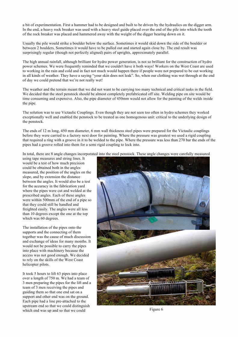
a bit of experimentation. First a hammer had to be designed and built to be driven by the hydraulics on the digger arm. In the end, a heavy rock breaker was used with a heavy steel guide placed over the end of the pile into which the tooth of the rock breaker was placed and hammered away with the weight of the digger bearing down on it. Usually the pile would strike a boulder below the surface. Sometimes it would skid down the side of the boulder or between 2 boulders. Sometimes it would have to be pulled out and started again close by. The end result was surprisingly regular (though not perfectly aligned) pairs of uprights, approximately parallel. The high annual rainfall, although brilliant for hydro power generation, is not so brilliant for the construction of hydro power schemes. We were frequently reminded that we couldn't have it both ways! Workers on the West Coast are used to working in the rain and cold and in fact not much would happen there if people were not prepared to be out working in all kinds of weather. They have a saying “your skin does not leak”. So, when our clothing was wet through at the end of day we could pretend that we’re not really wet! The weather and the terrain meant that we did not want to be carrying too many technical and critical tasks in the field. We decided that the steel penstock should be almost completely prefabricated off site. Welding pipe on site would be time consuming and expensive. Also, the pipe diameter of 450mm would not allow for the painting of the welds inside the pipe. The solution was to use Victaulic Couplings. Even though they are not seen too often in hydro schemes they worked exceptionally well and enabled the penstock to be treated as one homogenous unit: critical to the underlying design of the penstock. The ends of 12 m long, 450 mm diameter, 6 mm wall thickness steel pipes were prepared for the Victaulic couplings before they were carried to a factory next door for painting. Where the pressure was greatest we used a rigid coupling that required a ring with a groove in it to be welded to the pipe. Where the pressure was less than 270 bar the ends of the pipes had a groove rolled into them for a semi rigid coupling to lock into. In total, there are 8 angle changes incorporated into the steel penstock. These angle changes were carefully measured using tape measures and string lines. It would be a test of how much precision could be obtained both in the angles measured, the position of the angles on the slope, and by extension the distance between the angles. It would also be a test for the accuracy in the fabrication yard where the pipes were cut and welded at the prescribed angles. Each of these angles were within 500mm of the end of a pipe so that they could still be handled and freighted easily. The angles were all less than 10 degrees except the one at the top which was 60 degrees. The installation of the pipes onto the supports and the connecting of them together was the cause of much discussion and exchange of ideas for many months. It would not be possible to carry the pipes into place with machinery because the access was not good enough. We decided to rely on the skills of the West Coast helicopter pilots. It took 5 hours to lift 63 pipes into place over a length of 750 m. We had a team of 3 men preparing the pipes for the lift and a team of 3 men receiving the pipes and guiding them so that one end sat on a support and other end was on the ground. Each pipe had a line pre-attached to the upstream end so that we could distinguish which end was up and so that we could
Figure 5
Figure 6

secure the pipe so it would not slide down the hill. It was potentially very dangerous work but we put a lot of thought into safety and made sure that everyone was properly briefed and knew what to do and how to react. So, the job went smoothly with no one being put in danger. Connecting the pipes together was an efficient operation using a steel A frame and chain block to lift the downstream end of each pipe to line up with the pipe below so the Victaulic coupling could be clamped on. Some pipes needed to be rotated to achieve the best alignment between the faces of the rings welded on in the factory. One other feature of the steel penstock is worthy of note. The one anchor block near the bottom of the hill near the power house was designed to take 35 tons of force and is anchored to several massive boulders below the surface. It was designed to take the full load of the penstock. However, to reduce the load and to help with the expansion and contraction of the penstock up the hill, 4 pairs of heavy duty springs were installed. Each spring is loaded to 1.6 tons giving 3.2 tons of pull up the hill per pair and 12.8 tons of pull in total. (Figure 5) The springs are chained to clamps on the steel pipe and back to bolts drilled and epoxied into bedrock or to large buried boulders. The pipe is free to slide up and down the hill over PE saddles bolted to the cross member of each support. The resilience of the design was tested in the Kaikoura earthquake: marks on the pipe showed that it had skidded up and down the hill 20 mm each way before settling down exactly on original witness marks used to keep a check on the penstock. 5. Powerhouse equipment The powerhouse contains a single two jet Pelton turbine supplied by Hydroworks, a New Zealand company. Control and switchgear were designed by ElectroNet Services that is owned by Westpower, the local lines company. They have extensive experience in small hydro development because there are many small hydro schemes in the region. The power station’s electrical supply comprises of a local service transformer and a 2.125 MVA generator step up transformer. The generator transformer is a kiosk type that incorporates an 11kV Vacuum-insulated circuit breaker used for protection and synchronizing. The kiosk transformer was assembled off-site and simply transferred to a pre-built concrete foundation, reducing the amount of onsite construction. From the power station, an 11 kV cable is laid in protective ducting up a ridge, over the forest floor, to a short section of overhead line that connects the station to Westpower’s distribution network. As part of the project, Westpower’s network also had to be reinforced to carry the power station output. The connections shown in Figure 7 are all fully insulated pluggable connections allowing the generator to be easily isolated and earthed for maintenance. The control and automation is handled by a Schneider PLC and touchscreen HMI. The AVR is a Basler DECS-100 and a SEL-700G is used for all protection functions. During normal operation, a PID control loop determines spear positions required to maintain the Johnson intake tank level at 1.5m. Upon start-up, the PLC anticipates the spear positions based on the total available water at the intakes. This permits a rapid yet smooth start-up with low risk of draining the settling tanks. If the water level gets too low the station will automatically shut down and wait for the stream to rise before automatically restarting. Some basic control has been provided to Westpower which allows them to shut down or limit output for fault response or to carry out maintenance on their local network. Full manual control is available via the HMI for testing purposes. This is even possible over the internet using an App on a mobile device. Data logging of all parameters is conducted by the HMI allowing on-site and remote trending and the ability to download data via the internet. Emails are sent to the owners to alert them of alarms and trips. Fiber-optic cables are used for communication with the intakes. If communications are lost between the station and the intakes the sluice gates automatically open so shutting the station down.
Figure 7

Dave Mackay is the major shareholder, project developer and leader of the construction team. Richard Press is a consultant in mechanical engineering and was responsible for most of the mechanical design. Bryan Leyland helped with determining the initial concept and provided periodic advice.