Embed Size (px)
Citation preview

inLab SW 15 – SOFTWARE FEATURES This overview outlines the indications, tools, and materials according to the respective software versions starting with inLab SW 15.0. The respective changes to the previous version are listed.
OCTOBER 2015

inLab SW 15 SOFTWARE FEATURES | 02
inLab SW 15.0 OCTOBER 2015; CHANGES WITH RESPECT TO inLab SW 4.3
GENERAL
NEW INDICATIONS The following indications can be handled starting with inLab SW 15.0:
JAW-ORIENTED BIOGENERIC SETTINGStarting with this version, the entire scanned jaw is used as the basis for the restoration proposals. Especially with large jobs, this results in settings that are harmonious and appropriate to the individual situation. In addition to the biogeneric setting, the user also has the option of using tooth libraries for the initial proposal.
PARTIAL REMOVABLE DENTUREPartials can be designed with inLab SW 15.0 and the corresponding inLab Partial Framework plug-in. The scan is done in the inLab software and subsequently sent to the plug-in. The elements of the partial are then designed there.
SCREW-RETAINED BRIDGES AND BARSWith inLab SW 15.0, screw-retained bridges and bars can be designed on multi-unit abutments by Medentika® and nt-trading. Scanning of the implant positions requires inEos X5. In addition, special scan bodies (inPost) were developed to acquire the implant position. A separate gingiva element can also be created for the design. The jobs can then be imported in the inLab CAM software and milled in an inLab MC X5 unit.
CEREC GUIDE 2 (SURGICAL GUIDE)Surgical guides can be designed in inLab 15.0 in conjunction with the Galileos implant software. If the surgical guide is milled on an inLab MC X5 unit, it can extend over the entire jaw and include several drill holes.
NEW LICENSING SYSTEMThe inLab software is divided into modules that can be activated by a license.
inLab SW CAI LICENSEThis license includes the scanner and allows the models or impressions to be scanned and the data to be saved in the inLab data format or *.stl.
inLab SW 15.0 BASIC MODULE¢ Inlays, onlays, veneers, crowns, bridges, copings, bridge frameworks, multilayer restorations, models¢ All design tools, virtual articulator, Smile Design¢ Sirona Connect access¢ NEW: J.O.B.S (jaw-oriented biogeneric setting)¢ NEW: Tooth libraries¢ NEW: Virtual seating¢ NEW: Gingiva element
inLab SW 15.0 IMPLANTOLOGY MODULE (OPTIONAL)¢ Custom abutments and screw-retained crowns¢ NEW: Screw-retained bridges and bars on a multi-unit abutment¢ NEW: Surgical guide¢ OPEN GALILEOS implant interface for integrated implantology

inLab SW 15.0 REMOVABLES MODULE (OPTIONAL)¢ Telescopes, bars, attachments¢ NEW: Partial removable dentures
inLab SW 15.0 INTERFACE MODULE (OPTIONAL)¢ NEW: STL import of scan data (extraoral and intraoral scanners)¢ STL export of inLab restoration data¢ STL export of Sirona Connect intraoral scan data¢ STL export of model design data
inLab SW CAM LICENSEFor operation of the inLab CAM software and the manufacturing machines (inLab MC XL and inLab MC X5) controlled with it. NEW OPERATING CONCEPT¢ Several sidepanels can be opened simultaneously and positioned as desired on the screen . Using two monitors also allows the
sidepanels to be moved to the second monitor.¢ The restorations are active as soon as the mouse is moved over them. ¢ The step menu no longer includes mandatory steps, so each phase is gone through one step at a time.¢ OK/Cancel is no longer included in the steps; changes are applied by moving to the next step.
INSTALLATION REQUIREMENTS¢ inLab 4 PC HW v1.0.1 or higher¢ Recommended monitor resolution 1980 x 1080
SUPPORTED FILE FORMATS¢ *.lab ¢ *.dxd¢ *.cdt Import – This format is supported if the source is an inLab 3D v3.8x. – Only scan data (no images or restorations) can be imported.¢ *.3si / *.3se These formats can be imported or exported if there is an interface module license (successor to OPEN 3Shape license).¢ *.ssi This format can be exported if there is an OPEN GALILEOS implant license (integrated in the implantology module).¢ *.stl (import/export) – Scan data can be imported in this format. – Scan data can be exported in this format. – Model data (designed models) or restoration data can be exported in this format. – Intraoral scan data (CEREC AC) can be exported in this format. – The interface module license is required to export or import *.stl data.¢ *.cam This format can be exported for processing the restorations in the inLab CAM software.
INTERFACESSee supported formats
CONFIGURATION¢ Confi gurable material selection Manufacturers, materials, and block sizes can be activated or deactivated.¢ Parameter profi les Parameter profi les for materials, dentists, or machines can be created for each indication. These profi les can be selected by mouse
click during the design process.¢ Generic machine Non-Sirona manufacturing machines that can be selected for the design can be set up in the software. The number of axes, the
smallest milling radius, and the milling geometry can be selected.
NEW GROUPING FUNCTIONS VIA KEYBOARD SHORTCUTSStarting with this version, restorations can be grouped using the familiar Windows shortcuts SHIFT+click or CRTL+click.Administration phase
inLab SW 15 SOFTWARE FEATURES | 03
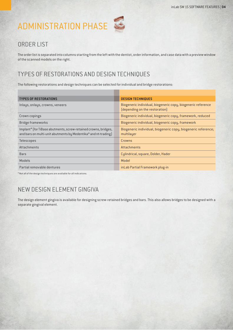
ADMINISTRATION PHASE
ORDER LISTThe order list is separated into columns starting from the left with the dentist, order information, and case data with a preview window of the scanned models on the right.
TYPES OF RESTORATIONS AND DESIGN TECHNIQUESThe following restorations and design techniques can be selected for individual and bridge restorations:
TYPES OF RESTORATIONS DESIGN TECHNIQUES
Inlays, onlays, crowns, veneers Biogeneric individual, biogeneric copy, biogeneric reference (depending on the restoration)
Crown copings Biogeneric individual, biogeneric copy, framework, reduced
Bridge frameworks Biogeneric individual, biogeneric copy, framework
Implant* (for TiBase abutments, screw-retained crowns, bridges, and bars on multi-unit abutments by Medentika® and nt-trading)
Biogeneric individual, biogeneric copy, biogeneric reference; multilayer
Telescopes Crowns
Attachments Attachments
Bars Cylindrical, square, Dolder, Hader
Models Model
Partial removable dentures inLab Partial Framework plug-in
* Not all of the design techniques are available for all indications.
NEW DESIGN ELEMENT GINGIVAThe design element gingiva is available for designing screw-retained bridges and bars. This also allows bridges to be designed with a separate gingival element.
inLab SW 15 SOFTWARE FEATURES | 04

MATERIALSThe following materials can be selected in the version for restorations. Depending on the type of machine, not all materials are always available:
SIRONA VITA IVOCLAR VIVADENT
CEREC BlocsCEREC Blocs CCEREC Blocs PCCEREC Blocs C PCCEREC Blocs C IninCoris ZIinCoris TZIinCoris TZI CinCoris CCinCoris CCBinCoris PMMAinCoris HTZI (infi niDent)inCoris NP (infi niDent)inCoris NPM (infi niDent)inCoris TI (infi niDent)inCoris TP (infi niDent)inCoris FI (infi niDent)inCoris WAX (infi niDent)
Mark IITriLuxeTriluxe ForteRealLifeEnamicSuprinitySuprinity FCYZ TYT HTCAD-WaxxCAD-Temp monoColorCAD-Temp multiColor
IPS Empress CADIPS Empress MultiIPS e.max CADIPS e.max ZirCADIPS AcrylCADTelio CAD
MERZ 3M ESPE GC
artBloc TempM-PM DiscPeek Bio Solution
LAVA UltimateLAVA Plus Disc
CerasmartInitial Zirconia Disk STInitial Zirconia Disk CT
DENTSPLY DEGUDENT MISC
Celtra Duo Cercon ht Zirconium oxideSintered metalWaxPMMACompositePEEKNon-precious metalPrecious metalTitanium
inLab SW 15 SOFTWARE FEATURES | 05

TI BASESAt present, the following implant systems are supported by the software:
MANUFACTURER TYPE DIAMETER
Astra Tech OsseoSpeed™ 3.5 S / 4.0 S 4.5 / 5.0
Biomet 3i Certain® 3.4 / 4.1 / 5.0
Biomet 3i Ex. Hex® 3.4 / 4.1 / 5.0
Dentsply Implants (Friadent) Frialit® / Xive® 3.4 / 3.8 / 4.5 / 5.5
Nobel Biocare Nobel Active® NP 3.5 / RP 4.3 / 5.0
Nobel Biocare Brånemark® NP 3.5 / RP 4.3 / 5.0
Nobel Biocare Replace® NP NP 3.5 / RP 4.3 / WP 5.0 / 6.0
Straumann Bone Level® 3.3 / 4.1 / 4.8
Straumann SynOcta® NN 3.5 / RN 4.8 / WN 6.5
Zimmer Tapered Screw-Vent® 3.5 / 4.5 / 5.7
Medentika® Implant M-Implant Tapered 3.5 / 5.0
CAMLOG CAMLOG® 3.3 / 3.8 / 4.3 /5.0 / 6.0
CAMLOG Conelog® 3.3 / 3.8 / 4.3 /5.0
CAMLOG iSy® 4.5
Thommen Medical Element / Contact 3.5 / 4.0 / 4.5 / 5.0 / 6.0
CASE DETAILSWhen the case is created, all the relevant information is displayed in the case details side panel. The case details can be displayed during the entire design process.
SCANNING PHASEinEos X5 UND inEos Blue The software supports the inEos X5 and inEos Blue scanners. CEREC acquisition systems are not supported.
BACKGROUND CALCULATION OF IMAGE CATALOGSThe 3D model of the individual image catalogs are calculated in the background during scanning.
TRIPLE TRAY IMPRESSION SCANNINGA special scanning technique for triple tray impression trays is available for the inEos X5 system.
ADDITIONAL IMAGE CATALOGS FOR SCREW-RETAINED BRIDGESA new image catalog was introduced for inEos X5 that enables scanning of the implant positions for screw-retained bridges and bars. New one-piece scan bodies (inPost) were developed for scanning screw-retained restorations. Starting with this version, screw-retained bridges and bars can be created on multi-unit abutments from Medentika® and nt-trading. The implant positions are scanned with the screwed-in multi-unit abutments on the lab analogs.
SCANNING WITHOUT RESTORATIONIt is possible to go to the scan phase and scan the model without creating a restoration, e.g., for a partial or a model to be saved as an STL fi le.
inLab SW 15 SOFTWARE FEATURES | 06

MODEL PHASEAUTOMATIC BUCCAL REGISTRATIONThe software automatically joins the upper and lower jaw models using the buccal image fi eld. Correction tools are still available.
MODEL AXIS EXTENDEDThe upper and lower jaws are now visible in the main window.
NEW STEP: EDIT JAWLINE In this step, the main jawline of the case is set and the tooth numbers of the preparations are dragged to their positions.
AUTOMATIC TRIMMING The software automatically trims the model or dies. Manual trimming is still available.
AUTOMATIC PREPARATION MARGINThe software automatically proposes the preparation line. The tools for correcting the line are still available.
SEATING AREAThe fi t of the restorations can be individually adjusted by means of the seating area option and the starting point of the spacer can be defi ned.
NO BASE LINE FOR PONTICS NECESSARYPontics are automatically proposed, therefore a drawing of the base line is no longer required.
NEW OPTIONS FOR SETTING THE INSERTION AXISStarting with this version, the insertion axis can also be set via the option viewing direction. The model is rotated in the insertion axis on the screen and then confi rmed. The insertion axis can also be set by touching the direction arrows.
DESIGN PHASE PARAMETER PROFILESThe parameter profi les created in the confi guration can be selected here for the individual restorations.
SEPARATE SPACER FOR OCCLUSAL AND RADIAL The spacer can be set separately for the occlusal and radial .
APPLY THE PARAMETERS TO ALLThis option can be selected if a parameter is to be applied to similar restoration elements.
NEW PARAMETERSThe following parameters were added in this version:
CROWNS, INLAYS, ONLAYS, BRIDGE FRAMEWORKS
PARAMETERS DESCRIPTION
Occlusal and radial spacer Space confi guration options for the fi xation material below the restoration. Acts up to the preparation margin.
Margin ramp angle Determines the angle at which the restoration rises from the margin.
Margin Ramp width Determines the length of the area with which the restoration rises from the preparation margin.
inLab SW 15 SOFTWARE FEATURES | 07

GINGIVA
PARAMETERS DESCRIPTION
Gingiva cleaning spacer Determines the distance from the gingiva element to the gingiva.The distance is also created at the edge of the gingiva element.
Gingiva spacer Determines the distance from the gingivaelement to the gingiva between the edges of the element. The edges always rest on the gingiva.
Gingiva implant spacer Determines the space between the gingiva element and adhesive cap of the abutment.
Minimum thickness of the gingiva
Determines the minimum wall thickness of the element.
Gingivaedge thickness Determines the material thickness at the edge of the element. Prevents splintering of the material.
Consider instrument geometry Takes the instrument geometry at the bottom of the restoration into consideration. Areas of the element that are smaller than the diameter of the instrument geometry are calculated at the base of the restoration in such a way that they are enlarged with the instrument geometry.
Removing undercuts Undercuts within the preparation margin are blocked out in the restoration base.
CEREC GUIDE 2
PARAMETERS DESCRIPTION
Thickness Thickness of the surgical guide
Spacer Distance between supporting surface on the residual teeth and inside of the guide body
ABUTMENT DESIGNNEW: TOOTH LIBRARIESStarting with this version, tooth libraries can be selected for the initial proposal. The following tooth libraries are available:¢ Candulor, Bonartic, Condyloform, Phyisoset, Physiostar¢ VITA: Physiodens, Lingoform, Vitapan Plus¢ Merz: Artegral
NEW STEP: MORPHOLOGYIn the morphology step, the tooth shape for the restoration can be selected. The following options for anterior teeth are available:¢ Biogeneric¢ Ovoid, square, and tapered¢ tooth librariesThe following options are available for the lateral teeth:¢ Biogeneric¢ tooth libraries
NEW STEP: POSITIONING In this step, the restorations can be positioned and scaled independently of the preparations. Along with the option of using the biogeneric application for the restoration proposal, it is also possible to let the software calculate precisely what was positioned.
NEW DESIGN TOOLS¢ Edit base line The base lines of the automatically proposed pontics can be changed using this tool.¢ New reduction functions Starting with this version, all the elements of a bridge can be reduced at the same time. The reduction line can be edited before the
reduction without having to switch to „partial reduction.“
inLab SW 15 SOFTWARE FEATURES | 08

PRODUCE PHASEinLab Kompakt AND inLab MC XL ARE SUPPORTEDBoth inLab Compact and inLab MC XL can be selected as milling machines, also the two simultaneously.
OTHER PRODUCTION OPTIONS¢ Export to inLab CAM¢ Export to folders (*.stl, *.lab, *dxd, *.ilab), for fabrication on other production machines
inLab SW 15 SOFTWARE FEATURES | 09


![inLab СВОБОДА ВЫБОРА В ЗУБОТЕХНИЧЕСKОЙ … · [Sirona] 2015 03 - inLab (32 А4).indd 1 02.04.2015 19:10:21 inLab CAD/CAM и inLab – теперь у вас](https://img.dokumen.tips/doc/110x75/5ed01cf0b6f1ac63cd2a2a2b/inlab-k-sirona-2015.jpg)