Embed Size (px)
Citation preview

INJECTION OF TREATED WASTEWATER FOR GROUND-WATER RECHARGE
IN THE PALO ALTO BAYLANDS, CALIFORNIA,
HYDRAULIC AND CHEMICAL INTERACTIONS--PRELIMINARY REPORT
By Scott N. Hamlin
U.S. GEOLOGICAL SURVEY
Water-Resources Investigations Report 82-4121
Prepared in cooperation with the
SANTA CLARA VALLEY WATER DISTRICT
COo
Ioo00 Sacramento, California
September 1983

UNITED STATES DEPARTMENT OF THE INTERIOR
JAMES G. WATT, SECRETARY
GEOLOGICAL SURVEY
Dallas L. Peck, Director
For additional information write to:
District ChiefU.S. Geological SurveyFederal Building, Room W-22352800 Cottage WaySacramento, California 95825
Copies of this report can be purchased from: Open-File Services Section Western Distribution Branch U.S. Geological Survey Box 25424, Federal Center Denver, Colorado 80225 Telephone: (303) 234-5888

CONTENTS
PageAbstract------------- ____________________________ __________________ jIntroduction------- ---------------------- ____ _ __________________ 2
Purpose and scope---- -------- __________ ______________________ 2Previous investigations----------------------- -------- _________ 4Acknowledgments- _____________________________ __________ _ __- 4
Geology--------------------- _____________ ______________ ___________ 5Lithology of the shallow baylands aquifer system-- _____-_______-- 6Geologic history------------------------------ ------------------- 6Local structure---------------------------------------------------- 9
Hydrology------------------------------ - - -------------- ---- --- 19Occurrence of ground water------------------- ---- - ___________ 19
Shallow baylands aquifer system------------------- __-___-_-- 19Deep baylands aquifer system---------- _-___--- ------------ 19
Aquifer hydraulic analysis-- ----------------------- _______ _ 21Conceptual model-------------------------- ----------- - -- 21Aquifer testing------- ---------- ----- ____ _______ ____ 21
Layer 1 - 21Layer 3 21
Water quality-------------------------- --------------------------__-__ 26Analyt i ca1 i nte rp re ta ti on---------------------------------- ---- 26Pilot injection test------------------------- -------------------- 28
Summary and conclusions--------------- -------------------------------- 32Future studies- ------------ ----- - _______________________ ____ 33Selected references-------------------- -------- ---------------- -_- 33Appendix A: Nuclear logs of wells---------------------------------- -- 38Appendix B: Drawdown data---------------- _-_-_----------------------- 50
ILLUSTRATIONS
Page Figures 1-2. Maps showing:
1. Location of the wastewater-reclamation studyarea---------- - -------------------------- 3
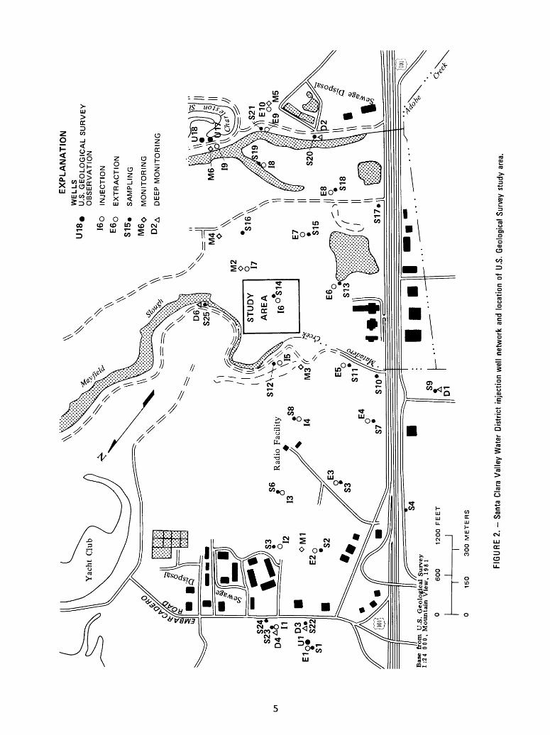
2. Santa Clara Valley Water District injection well network and location of U.S. Geological Survey study area------------------------- ---------- 5
3. Schematic cross section showing the baylands aquifersystems------------------- ------- ------------------- 7
4. Diagram showing chronology of sediments under southernSan Francisco Bay and correlation with baylands aquifer systems------------------------------------ ----------- g
III

Page Figures 5-6. Maps showing:
5. Marsh distribution, present and 1850 shorelines,and chloride contours- --- - - 10
6. Location of logged wells and geologic sections- 11 7-9. Geologic sections through the injection field:
7. A-A 1 128. B-B 1 139. C-C 1 14
10. Map showing location of the U.S. Geological Surveyobservation well network and sections in the studyarea ---- - --- -- - - 15
11-12. Geologic sections showing study area structure:11. X-X 1 1612. Y-Y' 17
13-14. Maps showing:13. Depth to bottom of the lower (45-foot) aquifer
near well 16- - ~~~~ ~ ~ ---- is14. Depth to water in the lower (45-foot) aquifer
near well I6-- - - ------ - --- 2015. Generalized geohydrologic cross section of the study
area 22 16-18. Graphs showing:
16. Drawdown data at well 16 from September 24,1980, extraction test 24
17. Drawdown in the upper (S14-shallow) and lower (Sl4-deep) aquifers during the September 24, 1980, extraction pump test - - - - 25
18. Type curves for drawdown in a two-aquifersystem separated by a leaky confining bed - 26
19. Map showing chloride concentration in the lower(45-foot) aquifer near well 16- - - - - --- 27
TABLES
Page Table 1. Chemical constituents of seawater, bay water, and ground water
in the vicinity of well 16- -- - - --- - 292. Dissolved solids and stable isotope determinations for shallow
ground water in the injection field- - -- 303. Chemical constituents of injection and ground water near
injection well 19, and drinking water regulations - 31
IV

CONVERSION FACTORS
For readers who prefer to use the International System of Units (SI) rather than inch-pound units, the conversion factors for the terms used in this report are listed below:
Multiply BYo oA (Angstroms) 0.0000001acres 0.4047 acre-ft (acre-feet) 0.001233 acre-ft/yr (acre-feet 0.001233per year)
feet 0.3048 ft/d (feet per day) 0.3048 ft 2 (square feet) 0.09290 ft 2 /d (feet squared 0.09290per day)
ft 3 (cubic feet) 0.02832 ft 3 /d (cubic feet 0.02832per day)
gal/min (gallons per 0.00006309minute)
(gal/min)/ft (gallons per 0.0002070minute per foot)
pmho/cm at 25°C (micromhos 1per centimeter at25 degrees Celsius)
min/ft 2 (minutes per 10.764square foot)
To obtain
mm (millimeters) hm2 (square hectometers) hm3 (cubic hectometers) hm3 /a (cubic hectometersper annum)
metersm/d (meters per day) m2 (square meters) m2 /d (meters squared per day)
m3 (cubic meters) m 3 /d (cubic meters
per day) m3/s (cubic meters per
second) m2 /s (meters squared
per second) pS/cm at 25°C (microsiemensper centimeter at25 degrees Celsius)
min/m2 (minutes per squaremeter)
ALTITUDE DATUM
National Geodetic Vertical Datum of 1929: A geodetic datum derived from a general adjustment of the first-order level nets of both the United States and Canada, formerly called mean sea level. The datum is referred to as sea level in this report.
TRADE NAMES
The use of trade names in this report is for identification purposes only and does not imply endorsement by the U.S. Geological Survey.
V

INJECTION OF TREATED WASTEWATER FOR GROUND-WATER RECHARGE
IN THE PALO ALTO BAYLANDS, CALIFORNIA,
HYDRAULIC AND CHEMICAL INTERACTIONS--PRELIMINARY REPORT
By Scott N. Hamlin
ABSTRACT
The U.S. Geological Survey, in cooperation with the Santa Clara Valley Water District, is studying the operation of the injection-extraction well network in the Palo Alto Baylands along the San Francisco Bay, California. The well network was designed to flush the shallow aquifer system of saline water and prevent further inland saline contamination. This study investi gates clogging processes and solution migration in the vicinity of one injection well.
A review of the geologic history of the area and previous ground-water studies indicates that cyclic evaporative concentration of bay water and infiltration have generated a concentrated ground-water brine. Montmoril- lonite and illite are the primary clay minerals present in the shallow aquifer system. X-ray diffraction analysis of these clays showed a marked increase in the d-spacing of the crystal lattice when native hypersaline pore water was replaced by injection water. Chloride:magnesium and chloriderpotassium ratios in the aquifer system changed during injection, most likely owing to ion- exchange reactions. Similar variations in chloridetboron, chloride:iron, and chloride:manganese ratios probably resulted from reduction-oxidation reac tions. Ground-water quality appears to have been chiefly affected by the processes of dilution and dispersion.
Extraction pump test data yielded a transmissivity value of 960 feet squared per day and a storage coefficient of 5x10 4 for the lower aquifer. Vertical hydraulic conductivity of the upper confining layer was 0.08 foot per day.

INTRODUCTION
The need for potable water resources in the south San Francisco Bay area is growing steadily, while suitable reserves are declining. By the year 2000, net water demands in California might exceed supplies by as much as 6.6 million acre-ft/yr. Wastewater reclamation and reuse are expected to reduce this figure by at least 600,000 acre-ft/yr, about 10 percent (Asano and Wassermann, 1979).
A major factor contributing to reduced quality and quantity of water supplies is saline contamination of ground water. In Santa Clara County, deterioration of the underground water resource is most severe in the Palo Alto-Los Altos-north Mountain View area (Jenks and Adamson, 1973). This area, known as the Palo Alto Baylands, is a marsh bounded by the 1850 shoreline to the west and by the present margin of San Francisco Bay to the east. A shallow zone of hypersaline ground water, adjacent to and paralleling San Francisco Bay, is a source of contamination to adjacent freshwater zones. The hypersaline ground water is concentrated in an aquifer complex comprising the upper 50 feet of sediment. This shallow baylands aquifer system, which under lies the marsh, contains an upper (20-foot depth) aquifer separated from a lower (45-foot depth) aquifer by a leaky clay layer. A lower freshwater zone, the deep baylands aquifer system below 150 feet in depth, is isolated from the shallow baylands aquifer by a thick clay confining bed. The salt problem in the shallow aquifer system is aggravated by local ground-water overdraft, which has reversed the original bayward potentiometric gradient. Overdraft has also resulted in inland subsidence (Iwamura, 1980).
Among the objectives of the Santa Clara Valley Water District is the prevention of ground-water quality degradation in the aquifers supplying various municipalities and industries in their district. Saline degradation of ground-water supplies is found chiefly around the southern San Francisco Bay. To alleviate this problem, the Santa Clara Valley Water District has constructed a pilot injection-extraction well network in the Palo Alto Baylands to form a freshwater barrier against inland saline migration. The wells are arranged in a series of injection-extraction pairs that form two lines parallel to the bay front. This arrangement is intended to allow injection of reclaimed water from the Santa Clara Valley Water District's advanced wastewater-treatment plant and eventual extraction of this water through inland wells. The aquifer is thereby flushed of saline contamination, and a freshwater barrier is established. Correct location of the injection- extraction network in relation to the saline contaminant source and inland ground-water usage is essential to the success of this project. The location of the Palo Alto wastewater-reclamation study area is shown in figure 1.
Purpose and Scope
The injection facility offers an excellent opportunity to study and evaluate the effectiveness of wastewater injection as a method of water reuse. A major obstacle to injection operations is clogging (reduced specific capa city) resulting from introduction of foreign water into an aquifer system. This phenomenon limits the efficiency of any injection-recharge system. The present study attempts to determine factors that affect injection-well performance.

122° 30'
37°45'
37° 30' 37°30'
Base from U.S. Geological SurveySan Francisco Bay Region, 1:125,000, 1970
122° 00'
10 15 KILOMETERS
FIGURE 1. - Location of the wastewater-reclamation study area.
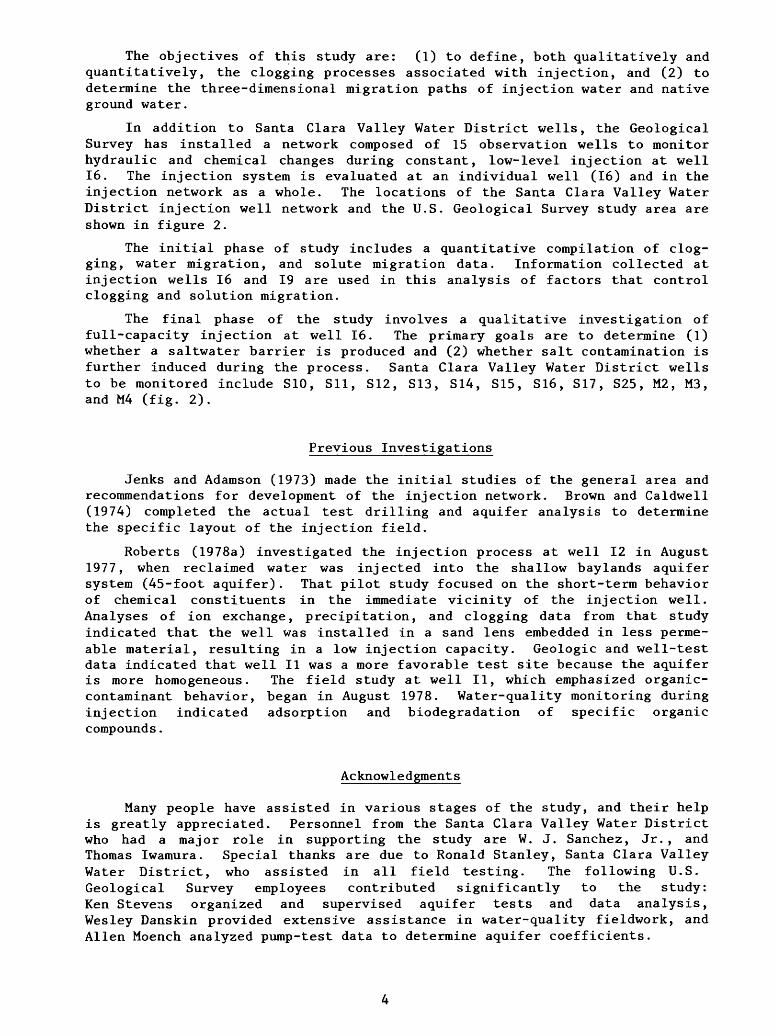
The objectives of this study are: (1) to define, both qualitatively and quantitatively, the clogging processes associated with injection, and (2) to determine the three-dimensional migration paths of injection water and native ground water.
In addition to Santa Clara Valley Water District wells, the Geological Survey has installed a network composed of 15 observation wells to monitor hydraulic and chemical changes during constant, low-level injection at well 16. The injection system is evaluated at an individual well (16) and in the injection network as a whole. The locations of the Santa Clara Valley Water District injection well network and the U.S. Geological Survey study area are shown in figure 2.
The initial phase of study includes a quantitative compilation of clog ging, water migration, and solute migration data. Information collected at injection wells 16 and 19 are used in this analysis of factors that control clogging and solution migration.
The final phase of the study involves a qualitative investigation of full-capacity injection at well 16. The primary goals are to determine (1) whether a saltwater barrier is produced and (2) whether salt contamination is further induced during the process. Santa Clara Valley Water District wells to be monitored include S10, Sll, S12, S13, S14, S15, S16, S17, S25, M2, M3, and M4 (fig. 2).
Previous Investigations
Jenks and Adamson (1973) made the initial studies of the general area and recommendations for development of the injection network. Brown and Caldwell (1974) completed the actual test drilling and aquifer analysis to determine the specific layout of the injection field.
Roberts (1978a) investigated the injection process at well 12 in August 1977, when reclaimed water was injected into the shallow baylands aquifer system (45-foot aquifer). That pilot study focused on the short-term behavior of chemical constituents in the immediate vicinity of the injection well. Analyses of ion exchange, precipitation, and clogging data from that study indicated that the well was installed in a sand lens embedded in less perme able material, resulting in a low injection capacity. Geologic and well-test data indicated that well II was a more favorable test site because the aquifer is more homogeneous. The field study at well II, which emphasized organic- contaminant behavior, began in August 1978. Water-quality monitoring during injection indicated adsorption and biodegradation of specific organic compounds.
Acknowledgments
Many people have assisted in various stages of the study, and their help is greatly appreciated. Personnel from the Santa Clara Valley Water District who had a major role in supporting the study are W. J. Sanchez, Jr., and Thomas Iwamura. Special thanks are due to Ronald Stanley, Santa Clara Valley Water District, who assisted in all field testing. The following U.S. Geological Survey employees contributed significantly to the study: Ken Stevens organized and supervised aquifer tests and data analysis, Wesley Danskin provided extensive assistance in water-quality fieldwork, and Alien Moench analyzed pump-test data to determine aquifer coefficients.
\\ \ ^ ^U
18
«
16 o
E6
0
S1
5.
M6
0
D2
A
EX
PL
AN
AT
ION
WE
LL
SU
.S.
GE
OLO
GIC
AL S
UR
VE
YO
BS
ER
VA
TIO
N
INJE
CT
ION
EX
TR
AC
TIO
N
SA
MP
LIN
G
MO
NIT
OR
ING
DE
EP
MO
NIT
OR
ING
Bas
e fr
om
U
.S.
Geo
log
ical
Surv
ey
1:2
4
000,
Mounta
in V
iew
, 1
98
1
150
30
0 M
ET
ER
S
FIG
UR
E 2
. S
anta
Cla
ra V
alle
y W
ater
Dis
trict
inj
ectio
n w
ell
netw
ork
and
loca
tion
of U
.S.
Geo
logi
cal
Surv
ey s
tudy
are
a.

GEOLOGY
Lithology of the Shallow Baylands Aquifer System
Alluvial deposits forming the lower and upper aquifers of the shallow baylands aquifer system (fig. 3) were laid down during late Pleistocene and Holocene time, respectively. These deposits consist of clay, silt, sand, gravel, and rarely peat. Graded sequences are common beneath the contact with Holocene estuarine deposits. Quartz and albite are the dominant minerals.
Estuarine deposits and shallow baylands aquifer confining clays were laid down during late Pleistocene to Holocene time in the San Francisco Bay area. Pleistocene deposits, consisting of clay, silty clay, and occasionally sand and gravel, commonly contain gypsum. Later deposits, which commonly contain framboidal pyrite (bio-organic deposition), are characterized by the "rotten eggs" odor of hydrogen sulfide. Desiccated samples may contain gypsum, limonite, and jarosite.
The dominant clay minerals are montmorillonite and, to a lesser extent, illite. Clay minerals from several aqueous environments were analyzed by X-ray diffraction. Clays from core samples containing hypersaline pore water were X-rayed to determine the d-spacing (distance between parallel planes in the crystal lattice). The samples were then soaked in typical injection water and X-rayed again. The d-spacing in one sample increased from 14.7 A to 19.6 A as a result of clay hydration and expansion.
Geologic History
The evolution of the shallow baylands aquifer system can be explained in terms of a changing depositional environment in response to sea-level fluctua tions and tectonic movement. Figure 4 is a time-stratigraphic correlation of sediments in the study area. The Holocene and upper Pleistocene alluvial deposits correlate with the upper and lower aquifer zones within the shallow baylands aquifer system discussed in detail in the "Hydrology" section.
Geologic events affecting the present aquifer system occurred during the Quaternary period. During the last Pleistocene glacial advance between about 70,000 and 10,000 years ago, sea level stood as much as 300-400 feet below its present elevation (Helley and Lajoie, 1979). The streams presently draining into the bay were merely tributaries of a large river flowing through the bay region from the Central Valley and across a broad, now submerged, coastal plain between the narrow canyon that is now the Golden Gate and the Farallon Islands. During this period, about 20,000 years ago, the lower aquifer of the shallow baylands aquifer system was deposited in freshwater conditions. Camels, bison, mammoths, sloths, and horses roamed the broad inland valleys, whose nearly flat floors were covered by freshwater marshes and open coniferous woodlands.

SOUT
HWES
T
ALL
UV
IAL
FANS
NORT
HEAS
T
SAN
F
RA
NC
ISC
O
BA
Y
GROUND-WATER RE
CHAR
GE AREA
BAYL
AND
MUD
FLATS
SHALLOW
BAYL
ANDS
AQUIFER
SYSTEM
DEEP
BAYLANDS
AQUIFER
SYST
EM
PERMEABLE
ALLU
VIAL
DEPOSITS (AQUIFER)
LESS
PE
RMEA
BLE
ESTU
ARINE
DEPOSITS (COMMONLY
ARE
CONF
ININ
G CLAYS)
FIG
UR
E 3
. - S
chem
atic
cro
ss s
ectio
n sh
owin
g th
e ba
ylan
ds a
quife
r sy
stem
s.

Adjacent land areas
Southern San Francisco Bay
Shallow baylands aquifer system
Deep baylands aquifer system
Alluvialdeposits
{ Holocene and late
.Pleistocene )
Eolian Deposits
(Holo cene
and late Pleisto cene )
Terrestrial and estuarine deposits,
undivided ( Pleistocene
and Pliocene?)
Tuff
Bedrock (Tertiary and Mesozoic)
0.2
0.4
0.6
0.8
1.0
Glaciationand
inter-glaciation
_» **o J5E ?
Tio9a Tahoe
O V
.§>(D «-> C
O.5 o o &
(5 V
11
Sea levels in New Guinea
Elevation, in meters
50 -25 0
-n-
-n-
- o§ o*c «~ o
5 <o
EXPLANATION
Unconformities
Interfingering of time- equivalent units
FIGURE 4. - Chronology of sediments under southern San Francisco Bay and correlation with baylands aquifer systems. (Modified from Atwater, Hedel, and Helley, 1977.)

122
07*3
0
37 27'3
0'
37°2
5' -
'SA
LT
E
VA
PO
RA
TO
R
EX
PL
AN
AT
ION
LIN
E
OF
E
QU
AL
CH
LO
RID
E
CO
NC
EN
TR
AT
ION
, IN
M
ILL
IGR
AM
S
PE
R
LIT
ER
SA
LT
WA
TE
R T
IDA
L
MA
RS
H
OF
B
AY
M
UD
A
ND
C
LA
Y
1850 S
HO
RE
LIN
E
00
.52
MIL
ES
J
0 0.
5 1
2 3
KIL
OM
ET
ER
S
FIG
UR
E 5
. -
Mar
sh d
istr
ibu
tion
, pr
esen
t an
d 18
50 s
hore
lines
, an
d ch
lorid
e co
ntou
rs.
About 15,000 years ago the sea level rose as glaciers in the northern latitudes began to melt. The local record of Holocene sea-level changes indicates that the rising sea entered the Golden Gate 10,000-11,000 years ago. During this time the upper aquifer of the shallow baylands aquifer system was deposited in a predominantly freshwater environment. The estuary reached the vicinity of Menlo Park about 8,000 years ago, and at the same time the charac ter of the bay changed to a predominantly saline environment. Subsequent shoreline changes have been more gradual because of a decrease in the rate of sea-level rise since 5,000-6,000 years ago, at which time the bay reached its present level. As the declining rate of sea-level rise was approached and surpassed by the rate of sediment accumulation, progradation of mudflats and salt marshes took place. Most bayward growth of marshes occurred within the last several thousand years.
The earliest European settlers in the bay area gathered salt that was naturally precipitated from tidal lagoons and along the margins of the bay. When these deposits were depleted around 1860, artificial evaporating ponds were constructed. Figure 5 compares the present with the 1850 shoreline and shows the correlation between chloride contours in the shallow baylands aquifer system and salt-marsh distribution.
Local Structure
The layout of the injection well network in the study area and location of sections developed from geologic and geophysical analysis are shown in figure 6. Sections A-A 1 , B-B 1 , and C-C' (figs. 7 through 9) show a downward slope of the lower aquifer from north to south and from east to west with a slight downwarped trough plunging south-southwest. The strata in this area are composed of alluvial-fan material interfingered with estuarine clay deposited during a period of tectonic activity and sea-level fluctuation.
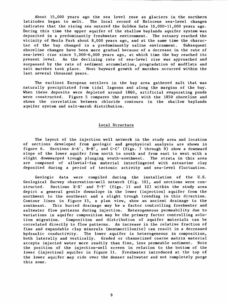
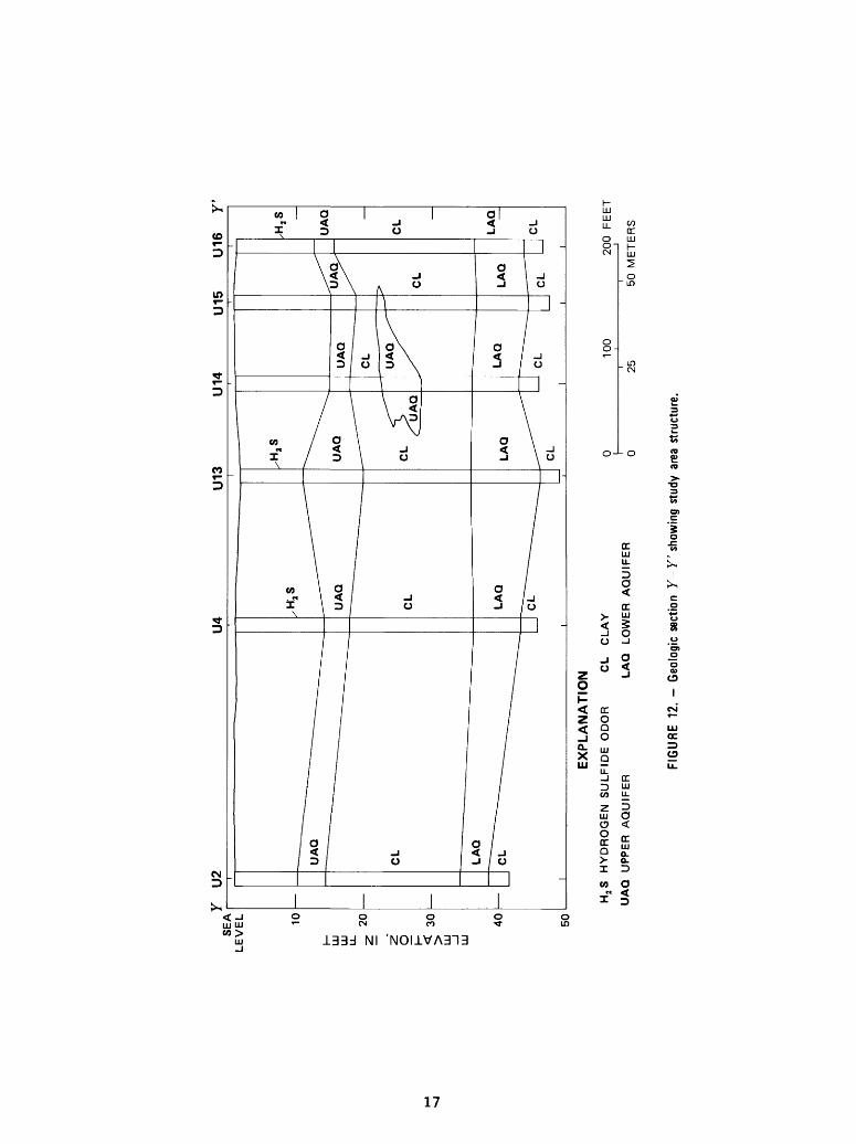
Geologic data were compiled during the installation of the U.S. Geological Survey observation-well network (fig. 10), and sections were con structed. Sections X-X 1 and Y-Y 1 (figs. 11 and 12) within the study area depict a general gentle downslope in the lower (injection) aquifer from the northwest to the southeast and a slight trough trending in this direction. Contour lines in figure 13, a plan view, show an ancient drainage to the southeast. This buried drainage may be a factor controlling freshwater and saltwater flow patterns during injection. Heterogeneous permeability due to variations in aquifer composition may be the primary factor controlling solu tion migration. Composition and distribution of aquifer materials can be correlated directly to flow patterns. An increase in the relative fraction of fine and expandable clay minerals (montmorillonite) can result in a decreased hydraulic conductivity. The lower aquifer is heterogeneous in composition, both laterally and vertically. Graded or channelized coarse matrix material accepts injected water more readily than fine, less permeable sediment. Note the position of the injection-well screen in relation to the bottom of the lower (injection) aquifer in figure 11. Freshwater introduced at the top of the lower aquifer may ride over the denser saltwater and not completely purge this zone.

EX
PL
AN
AT
ION
INJE
CT
ION
WE
LL
EX
TR
AC
TIO
N W
ELL
SA
MP
LIN
G W
ELL
MO
NIT
OR
ING
W
ELL
A-A
' L
INE
OF
SE
CT
ION
TH
RO
UG
H
TH
E
INJE
CT
ION
F
IELD
Y-Y
' L
INE
OF
SE
CT
ION
T
HR
OU
GH
T
HE
S
TU
DY
AR
EA
Bas
e fr
om U
.S.
Geo
logi
cal
Surv
ey
1:24
0
00
, M
oun
tain
Vie
w,
1981
150
30
0
ME
TE
RS
FIG
UR
E 6
. - L
ocat
ion
of l
ogge
d w
ells
and
geo
logi
c se
ctio
ns.

SE
A
LE
VE
L
EX
PL
AN
AT
ION
UA
Q
UP
PE
R
AQ
UIF
ER
LA
Q
LO
WE
R
AQ
UIF
ER
CLA
Q
CLA
YE
Y
AQ
UIF
ER
CL
C
LA
Y
_
(Fro
m
appendix
A
,n
ucl
ea
r lo
gs o
f w
ells
)
S12
, M
3,
S10
SA
NT
A
CLA
RA
V
AL
LE
Y
WA
TE
R
DIS
TR
ICT
O
BS
ER
VA
TIO
N W
ELLS
0 10
0 20
0 M
ET
ER
S
FIG
UR
E
7.
Geo
logi
c se
ctio
n A
-A'
thro
ugh
the
inje
ctio
n fie
ld.

M6
B'
50
100
20
0
ME
TE
RS
AQ
A
QU
IFE
R
MA
TE
RIA
L
UA
Q
UP
PE
R
AQ
UIF
ER
LA
Q
LO
WE
R
AQ
UIF
ER
EX
PL
AN
AT
ION
CL
AQ
C
LA
YE
Y
AQ
UIF
ER
CL
C
LA
Y
(Fro
m
appendix
A
, n
ucl
ea
r lo
gs
of
wells
)
S12,
S14,
M2,
S16,
M6,
SA
NT
A C
LA
RA
V
ALLE
YW
AT
ER
D
IST
RIC
T
OB
SE
RV
AT
ION
WE
LL
S
FIG
UR
E 8
. G
eolo
gic
sect
ion
B-B
'thr
ough
the
inj
ectio
n fie
ld.

CL
AQ
A
QU
IFE
R
MA
TE
RIA
L
UA
Q
UP
PE
R
AQ
UIF
ER
LA
Q
LO
WE
R
AQ
UIF
ER
CL
CL
AY
(Fro
m
ap
pe
nd
ix
A,
nu
cle
ar
logs
of
wells
)
S7, S
10,S
13,S
15,S
17S
AN
TA
C
LA
RA
V
ALLE
Y
WA
TE
R
DIS
TR
ICT
O
BS
ER
VA
TIO
N
WE
LL
S
40
0800
FE
ET
0
100
200
ME
TE
RS
FIG
UR
E 9
. - G
eolo
gic
sect
ion
C-C
' th
roug
h th
e in
ject
ion
field
.

EXPLANATION
,U2 U.S. GEOLOGICAL SURVEY OBSERVATION WELL
0 I6 INJECTION WELL
.814 SAMPLING WELL
Y-Y' LINE OF SECTION
200 FEET
50 METERS
FIGURE 10. - Location of the U.S. Geological Survey observation well network and sections in the study area.
15

SEA
x
U8
U9
U10
16
U
11
U12
U
13
US
I C
V/C
I - . .
, -^
i i i i
U6
U7
LtV
tU 10
I- ILJ
LU
LL Z
20
z*
o
I- <
30LU _
J LU
40
50
I
UA
Q
\
CL
LA
Q
CL
-j- I
UA
Q
CL LA
Q
I
*.
UA
Q
^^"
CL
LA
Q u
j ui
cc
o V)
CL
:s s.
I
^
\^
,H,S
<^
UA
Q
CL LA
Q
^^
CL
I
__
^
UA
Q
2k~
?
UA
Q
CL
LA
Q
^^
CL
I
EX
PL
AN
AT
ION
H,S
H
YD
RO
GE
N
SU
LF
IDE
O
DO
R
CL
CL
AY
UA
Q
UP
PE
R
AQ
UIF
ER
L
AQ
LO
WE
R
AQ
UIF
ER
__
_U
AQ
CL
^^~
~~
~-
.
"
LA
Q
- _
__
__
CL
I
UA
Q
CL_^.
UA
Q
CL
_
LA
Q
CL
0 10
0 20
0 F
EE
T
0
25
50
ME
TE
RS
FIG
UR
E
11.-
Geo
logi
c se
ctio
n X
-X'
show
ing
stud
y ar
ea s
truct
ure.
Y
U2
EX
PL
AN
AT
ION
H2
S
HY
DR
OG
EN
S
UL
FID
E
OD
OR
C
L
CL
AY
UA
Q
UP
PE
R
AQ
UIF
ER
L
AQ
LO
WE
R
AQ
UIF
ER
U13
U14
U15
U
16
Y'
100
200
FE
ET
25
50 M
ET
ER
S
FIG
UR
E
12. G
eolo
gic
sect
ion
Y Y
' sh
owin
g st
udy
area
stru
ctur
e.
X'
EXPLANATION
,U2 U.S. GEOLOGICAL SURVEY OBSERVATION WELL
.16 INJECTION WELL
.814 SAMPLING WELL
Y-Y' LINE OF SECTION
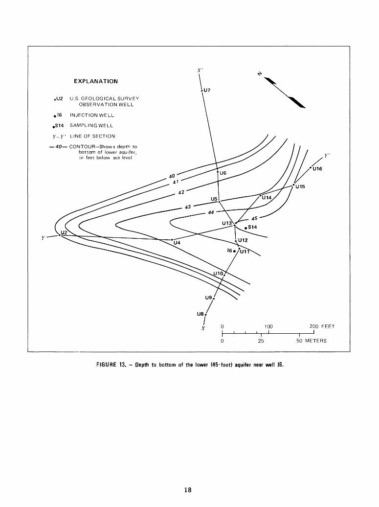
40 CONTOUR-Shows depth to bottom of lower aquifer, in feet below sea level
U16
25I
50 METERS
FIGURE 13. - Depth to bottom of the lower (45-foot) aquifer near well 16.
18
HYDROLOGY
Occurrence of Ground Water
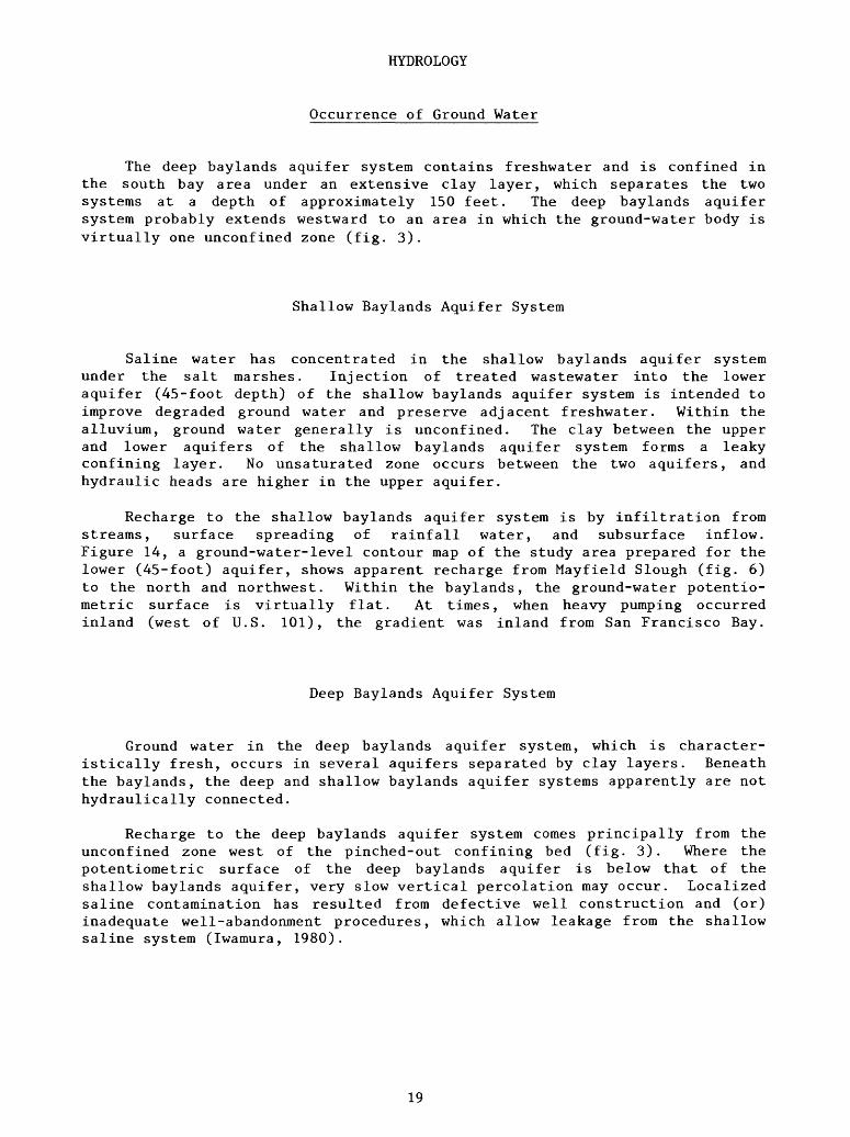
The deep baylands aquifer system contains freshwater and is confined in the south bay area under an extensive clay layer, which separates the two systems at a depth of approximately 150 feet. The deep baylands aquifer system probably extends westward to an area in which the ground-water body is virtually one unconfined zone (fig. 3).
Shallow Baylands Aquifer System
Saline water has concentrated in the shallow baylands aquifer system under the salt marshes. Injection of treated wastewater into the lower aquifer (45-foot depth) of the shallow baylands aquifer system is intended to improve degraded ground water and preserve adjacent freshwater. Within the alluvium, ground water generally is unconfined. The clay between the upper and lower aquifers of the shallow baylands aquifer system forms a leaky confining layer. No unsaturated zone occurs between the two aquifers, and hydraulic heads are higher in the upper aquifer.
Recharge to the shallow baylands aquifer system is by infiltration from streams, surface spreading of rainfall water, and subsurface inflow. Figure 14, a ground-water-level contour map of the study area prepared for the lower (45-foot) aquifer, shows apparent recharge from Mayfield Slough (fig. 6) to the north and northwest. Within the baylands, the ground-water potentio- metric surface is virtually flat. At times, when heavy pumping occurred inland (west of U.S. 101), the gradient was inland from San Francisco Bay.
Deep Baylands Aquifer System
Ground water in the deep baylands aquifer system, which is character istically fresh, occurs in several aquifers separated by clay layers. Beneath the baylands, the deep and shallow baylands aquifer systems apparently are not hydraulically connected.
Recharge to the deep baylands aquifer system comes principally from the unconfined zone west of the pinched-out confining bed (fig. 3). Where the potentiometric surface of the deep baylands aquifer is below that of the shallow baylands aquifer, very slow vertical percolation may occur. Localized saline contamination has resulted from defective well construction and (or) inadequate well-abandonment procedures, which allow leakage from the shallow saline system (Iwamura, 1980).
19

X'
EXPLANATION
,U2 U.S. GEOLOGICAL SURVEY OBSERVATION WELL
.16 INJECTION WELL
.514 SAMPLING WELL
Y-Y' LINE OF SECTION
-4.95 WATER-LEVEL CONTOUR- Shows depth to water, in feet below sea level.
U7
' 0 100J\. i i i 1
10 25
150
200 FEET1
METERS
FIGURE 14. - Depth to water in the lower (45-foot) aquifer near well 16.
20

Aquifer Hydraulic Analysis
Conceptual Model
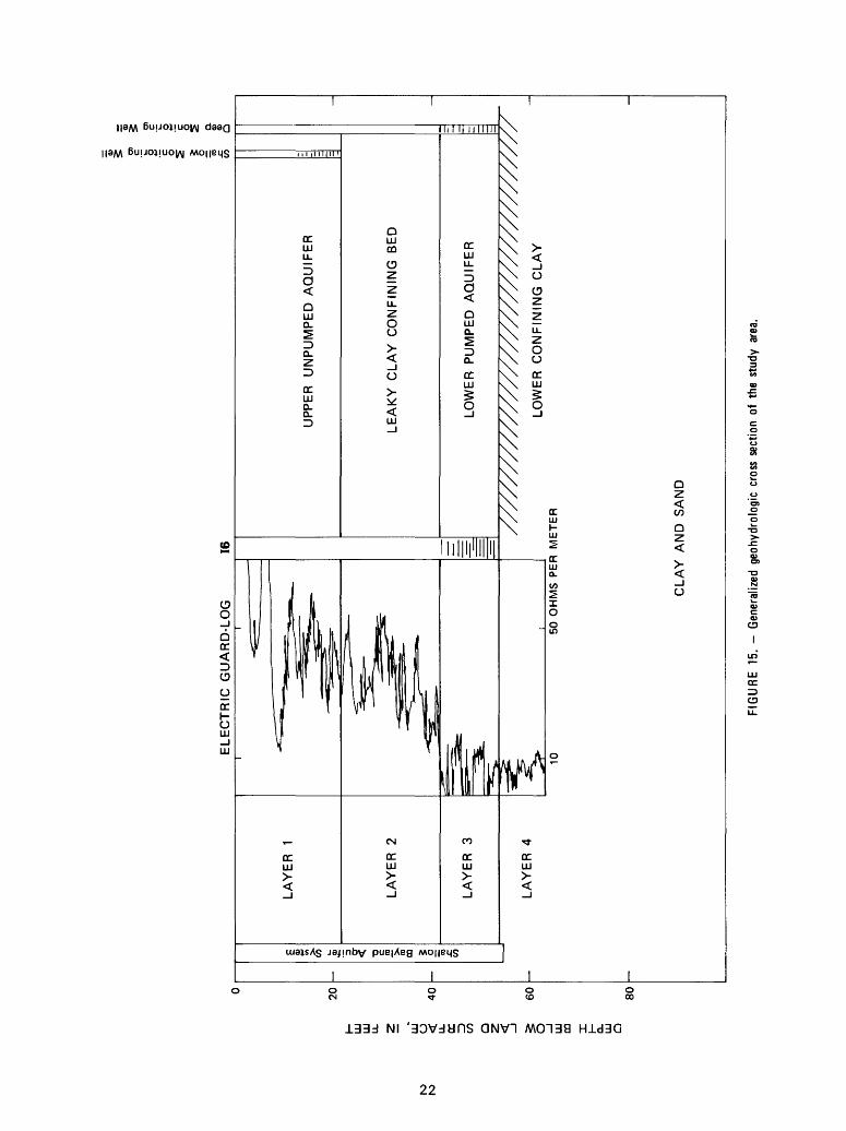
Analysis of ground-water data to determine aquifer characteristics requires an understanding of the geologic framework. The shallow baylands aquifer is conceived as a four-layer system as shown in figure 15. Layer 1, containing the uppermost aquifer, is treated as a source bed with good hydrau lic connection to the land surface. An intermediate leaky clay confining bed, layer 2, separates the upper unpumped aquifer from the lower pumped aquifer, layer 3. This lower aquifer is underlain by a confining clay layer, layer 4. To reduce the numerical complications of three-dimensional analysis, ground- water flow is assumed to be horizontal in the aquifers (layers 1 and 3) and vertical in the leaky clay confining bed (layer 2).
In the vicinity of 16, a salinity gradient exists between the upper and lower aquifers as shown in figure 15 by the electric guard-log. A guarded- electrode system was used to measure formation resistivity through conductive drilling mud in an uncased hole. This electrical logging tool is focused and gives good vertical resolution and penetration. A sharp drop in electrical resistance is seen between the upper ground water (layers 1 and 2) and the lower more saline ground water (layer 3), indicating a density layering of ground water. Preinjection specific-conductance values for the upper and lower aquifers were 35,000 and 70,000 jjmho/cm at 25°C, respectively.
Aquifer Testing
Layer 1.--Brown and Caldwell (1974) made hydraulic tests in the upper (20-foot) aquifer in the vicinity of injection well II. Drawdown data were collected while water was being pumped at 8.6 gal/rain (1,650 ft3/d). Both drawdown and recovery data were analyzed using the leaky-artesian formula of Hantush and Jacob (1955). Leakage was noted from the 45-foot aquifer and from the overlying soil layer. Interpretation was complicated by the inherent error associated with the small magnitude of drawdown; however, the recovery data were considered adequate for hydraulic analysis. The transmissivity was 470 ft2/d, and the storage coefficient was 0.002.
Layer 3.--In September 1980 an extraction test was run at well 16 in which water from the lower (45-foot) aquifer was withdrawn at a rate of 1,930 ft3/d. Drawdown was measured at observation wells Ull (20 feet from 16) and S14 (55 feet from 16) and at the pumped well 16 for a period of 1,500 minutes. Water levels were recorded by Stevens Type F recorders coupled with Keck water-level followers using modifications described by M. S. McBride and S. P. Larson (U.S. Geological Survey, written coimnun., 1972). Water-level measurements were made at the rate of 10 per log cycle of drawdown. The plan of the test area is shown in figure 10, and drawdown data are shown in Appendix B. Distant observation wells S13 shallow and deep (1,000 feet from 16) were measured with a steel tape, and they showed no appreciable drawdown during the test.
21
h- ULJ
ULJ
ULJ
U oc ID
CO
5
§
§
5=
Q
.
ELE
CT
RIC
G
UA
RD
-LO
G
16CO
DO I Q.
UJ
Q
UP
PE
R
UN
PU
MP
ED
AQ
UIF
ER
LE
AK
Y
CL
AY
C
ON
FIN
ING
B
ED
LOW
ER
P
UM
PE
D
AQ
UIF
ER
LOW
ER
C
ON
FIN
ING
CL
AY
50
OH
MS
P
ER
M
ET
ER
CL
AY
A
ND
S
AN
D
80 -
FIG
UR
E
15. - G
ener
aliz
ed g
eohy
drol
ogic
cro
ss s
ectio
n of
the
stu
dy a
rea.

In order to take into consideration the leaky-artesian, nonequilibrium characteristics of the test data from this aquifer, the modified Hantush method (Hantush, 1961) of analysis was used. This method of hydraulic analysis accounts for storage of water in the confining bed and assumes constant head, or zero drawdown, in the upper aquifer.
The analysis of data by this method consists of attempting to match one of the family of type curves to the data using a superposition procedure. The type curves are generated through the basic equation:
u
H(u,p) = / Y~ erfc I » dv (1)
where r 2 S, 11 4Tt
r k'Ss'K 4b \K kSs 1 kSs
y = the variable of integrationk = hydraulic conductivity of the main aquifer,
k 1 , k" = hydraulic conductivities of the confining layers,b = thickness of aquifer,S = bSs j storage coefficients of the main aquifer
S' = b'Ss' > and of the confining layers,S" = b"Ss" ) respectively,
Ss, Ss', Ss" = specific storage,r = radial distance from observation well to pumped
well,T = transmissivity, andt = time since pumping began.
Transmissivity is determined from the following relationship:
T = JL H (u,p), (2)
where Q = flow rate, ands = head change (drawdown or head buildup).
The drawdown data for observation wells Ull (r = 20 feet) and S14 (r = 55 feet) have been plotted with respect to time normalized by radius squared (fig. 16). A match to the H(u,p) type curve was made at H(u,p) = u = 1. This corresponds to an s value of 0.16 feet and a t/r2 value equal to 1.8 x 10 4 min/ft2 . Through algebraic manipulation, transmissivity, T, was determined to be 960 ft2 /d. Similarlyj the storage coefficient S of the pumped aquifer was calculated to be 5 x 10 4 . This value falls within the range for confined aquifers, between 10 5 and 10 3 .
An upward break in slope, approaching a Theis response (confined non- leaky aquifer), in the drawdown data probably indicates the effect of drawdown in the upper aquifer. This effect is not accounted for in the modified Hantush (1961) method, which assumes constant head in the layers above the pumped aquifer. Drawdown in the unpumped aquifer reduces the head differen tial between upper and lower aquifers which, in turn, reduces downward leakage
23

10IIII
I I
I IIIIII
I I
l_
1.0
111 111 o
o I oc
o
(1,1)
0.1
- A
.A
O
0.01 0.
0001
I I
I
EX
PL
AN
AT
ION
O
U11
(2
0 fe
et
fro
m
16)
A
S14
(5
5 fe
et fr
om
16
) _
t T
ime,
in
min
ute
s si
nce
pum
pin
g
bega
n
r D
ista
nce
fro
m
16 t
o
mea
sure
d w
ell
Q
10 g
al/m
in=
1930 f
t /d
(1
1)
Mat
ch
poin
t on
H
(u
,j3)
plo
t,
^ m
odifi
ed
Han
tush
, 19
61
s=0
.16
, t/r2
= 0.
0001
8
i i
i i
i i
i I_
__
__
i i
i i
i i
i i I_
____i
i i
i i
i i
i0.
001
0.01
0.1
1.0
10
t/r
FIG
UR
E
16. -
Dra
wdo
wn
data
at
wel
l 16
fro
m S
epte
mbe
r 24
, 19
80,
extr
actio
n te
st.

through the confining layer, thereby increasing drawdown in the lower pumped aquifer. To determine the vertical permeability of the confining layer, A. F. Moench (written commun., May 1981) has analyzed drawdown data from observation wells completed in the upper and lower aquifers at the same radius (fig. 17). This method of analysis incorporated the two-aquifer theory of Neuman and Witherspoon (1969) and a method for evaluating the equations described by A. F. Moench and Akio Ogata (written commun., 1981). The data plot was matched to the theoretical type curve shown in figure 18, yielding an estimated vertical hydraulic conductivity of 0.08 ft/d. Application of this technique required known values of pumped-aquifer transmissivity and storage, as computed above, and known thicknesses of the aquifers and intervening confining layer. It was assumed that the lower, confining layer (layer 4 in fig. 15) contributed no flow to the aquifer. An aquifer test done in the upper aquifer can more clearly define the calculated vertical hydraulic conductivity of the upper confining layer.
Ken Stevens (U.S. Geological Survey, written commun., Sept. 1980) has analyzed aquifer-test data from Brown and Caldwell (1974) and Stanford University (Albert J. Valocchi, Stanford University, written commun., 1980) to determine aquifer characteristics. At injection well II the following values were determined: transmissivity, 530 ft2/d; storage coefficient, 1 x 10 4 ; and vertical conductivity, 1 ft/d. Transmissivity was 400 ft2/d at injection well 12. The higher value for transmissivity at injection well 16 (960 ft2/d) may be explained by the presence of very coarse aquifer material, possibly the axis of an ancient drainage channel, in the vicinity of the injection well.
10
1.0
mHI
OQ
1ocQ
0.1
I I I I I I I I I I I I I I I 11 I I I I I I I I
X
x x/
X X 3?x^ xx
0<?*EXPLANATION
XX )Q( t Time, in minutes since pumping began
X< r Distance from 16 to measured well XX
X
I . .... ...I0.010.00001 0.0001 0.001 0.01 0.1 1.0
t/r 2
FIGURE 17. - Drawdown in the upper (S14-Shallow) and lower (S14-Deep) aquifers during the September 24, 1980, extraction pump test.
25

NEUMAN-WITHERSPOON TYPE CURVES100
10
QX
0.10.1 1.0 100010 100
TD (DIMENSIONLESS)
FIGURE 18. - Type curves for drawdown in a two-aquifer system separated by a leaky confining bed.
10,000
WATER QUALITY
Analytical Interpretation
Concentration of dissolved solids in the study area decreases both toward and away from the bay. Apparently, a "ridge" of concentrated brine occupies the shallow baylands aquifer system in this vicinity. The shape of this ridge, delineated by chloride concentration contours (fig. 5), is a product of (1) recharge from local streams, surface percolation, and bay water infiltra tion; and (2) the mechanisms that have produced the hypersaline brine: evapo rative concentration, percolation, and ion-exchange reactions. Figure 19 shows lines of equal chloride concentration in the lower (45-foot) aquifer within the study area.
26

X'
,U2
EXPLANATION
U.S. GEOLOGICAL SURVEY OBSERVATION WELL
^28
s <?<5^
.16 INJECTION WELL
.514 SAMPLING WELL
Y-Y' LINE OF SECTION
26 LINE OF EQUAL CHLORIDE CONCENTRATION - Interval,
2 grams per liter
X
50 METERS
FIGURE 19. - Chloride concentration in the lower (45-foot) aquifer near well 16.
Various chemical constituents and ratios indicate geochemical processes in the ground-water system. Chloride, the major anion of seawater, moves through the aquifer at nearly the same rate as the intruding water. Where no other saline contamination exists, increasing chloride concentration can be considered an indication of sea water contamination. Ionic ratios are useful in differentiating between water types, such as bay water and ground water. Absolute concentrations of individual dissolved constituents may vary during such physical processes as dispersion, dilution, and evaporative concentra tion, whereas ionic ratios remain constant. Chemical interactions between solutions and between solutions and solids alter these ionic ratios. Hence, ionic ratios can be used to discriminate between physical and chemical inter actions involved in the genesis of a particular water type. ClrBr ratios are commonly used to classify water types. A low Ca:Mg ratio may indicate sea- water contamination, as magnesium concentration in seawater is much greater than that of calcium.
27

Chloride, other major ions, and some trace metals show similar propor tions in seawater, bay water, and ground water as indicated in table 1. The Cl:Br ratios in ground water and seawater are nearly identical (Kharaka, U.S. Geological Survey, written commun., 1977). Samples taken at well 12 yielded values for chloride and bromide concentration of 3,450 mg/L and 11.6 mg/L, respectively. The calculated Cl:Br ratio is 297, as compared to an average value of 292 for sea water. Major ions in the saline ground water are approximately twice the corresponding concentration in seawater. Ca:Mg ratios, ranging between 0.30 and 0.39, are also similar in seawater, bay water, and ground water. Seawater, bay water, and ground water have similar ratios of C1:S04 , ClrMg, Cl:Na, Cl:Ca, and C1:K (table 1). The SAR (sodium adsorption ratio), which is highest for ground water, indicates a high ten dency for sodium replacement of adsorbed calcium and magnesium in the geologic matrix. These observations support the theory that the shallow ground water has been derived chiefly from concentrated bay water.
Measurements of the stable isotope ratios of hydrogen and oxygen provide evidence that the formation brines in the study area have a history of expo sure to evaporative conditions (Roberts and others, 1978b). Roberts' isotopic data plotted in a regression analysis produced a straight line, which suggests that the ground water was formed by mixing two different types of water. These data, along with dissolved-solids concentrations, are shown in table 2. From the intercept and slope of this regression line the author has postulated that these types are a mixture of imported water and seawater concentrated by evaporation. The highly saline ground-water samples showed the highest con centration in 180. Evaporation tends to fractionate the heavier 180 in the liquid phase and the lighter 160 in the vapor phase. Relatively constant values for major ionic ratios among sea, bay, and ground water support the theory of cyclic evaporative concentration. Thus, the hypersaline water is most likely a product of cyclic evaporitive concentration of saline bay water and downward solute transport by surface percolation. Higher density brine tends to accumulate in the lower -aquifer zone and to grade upward into fresher water.
Pilot Injection Test
Ground-water quality was monitored during June and July 1980 from the start of injection at well 19, located at the southern end of the injection network (fig. 2). Table 3 shows concentrations of various constituents in ground water in observation well U17 (about 31 feet from injection well 19), before and after one month of injection. Also shown are drinking water regu lations and a chemical analysis of the injected water to illustrate the effectiveness of injection in replacing and upgrading ground-water quality.
Major ion concentrations of ground water have been reduced primarily by the processes of dilution and dispersion. Cl:Na, Cl:Ca, and C1:S04 ratios show little change during injection, indicating simple dilution of ground water by injection water. Cl:Mg and C1:K ratios, however, do vary noticeably during injection. Ion-exchange reactions between clays and organic compounds in the aquifer probably account for these variations. C1:B, Cl:Fe, and Cl:Mn ratios also vary most likely as a result of reduction-oxidation reactions. These effects are superimposed on the proportional mixing of ground and injec tion water, yielding intermediate values for ionic ratios. Copper and arsenic concentrations remained constant during ground-water dilution and replacement by injection water. With respect to major ion concentrations, ground-water quality has greatly improved in the immediate vicinity of injection well 19.
28

TABLE 1. - Chemical constituents of seawater, bay water,and ground water in the vicinity of well 16
Constituentand 0 .1 Bay . . Seawater x ' 2 character- water^
istics
Cl 19Na 10S04 2Mg 1
CaKSi02B
FFeAsCu
MnAgCdCaC03
(Alkalinity)
SAR3Ca:MgC1:S04Cl:Mg
Cl:NaClrCaC1:KCl:Fe 1,900
Cl:Mn 9,500C1:B 4
^rom Hem, 19702From Iwamura,
Milligrams per
,000 14,500 8,700 2,350 1
400380
6.44.6
1.3.01.003.003
.002
.0003
.00011116
Ratios
56.30
7.0414.1
1.8147.550
,000 147
,000,130 3
1980.3SAR (sodium adsorption ratio)
liter
,700,400,200,000
315380
3.8
1.10
__ 150
52.32
6.6814.7
1.7546.739
,000
,870
= (Na) / /Ca/ if
Ground water
27,90015,8003,3502,180
840480136
.2
.34
.002
.008
15.50.011
815
65.39
8.3312.8
1.7733.258
82,000
1,8004,650
+ Mg2
29

TABLE 2. - Dissolved solids and stable isotope determinationsfor shallow ground water in the injection field
(From Roberts and others, 1978c)
Well number
Il-lower
Il-upper
M3- lower
Si-lower
83-lower
S3-upper
S7-lower
S7-upper
S9-lowe*r
SlO-lower
Sll-lower
Sl2-lower
S25-lower
Dissolved solids (mg/L)
4,250
6,600
58,100
4,800
44,900
9,260
51,800
45,500
22,600
35,300
23,200
67,700
62,300
Deviation from Standardin parts per
Oxygen- 18 6180
-6.20
-7.22
-1.65
-5.73
-2.16
-5.57
-0.71
-2.12
-5.53
-3.38
-4.79
-2.28
-2.24
Mean Ocean Water,thousand
Deuterium 6D
-49.8
-55.1
-22.5
-43.8
-26.5
-43.3
-19.2
-25.8
-45.5
-32.8
-39.9
-26.3
-26.5
30

TABLE 3. - Chemical constituents of injection and ground water near injection well 19 1 ) and drinking-water regulations
Ground waterConstituent Before
injectionAfter 1-month
injection
Injection water
Drinking-water regulations2
Milligrams per liter
ClNaS04MgCaK
Si02BFFeAs
Cu Mn Ag Cd CaC03
26,00015,0003,4002,000
750390
194.8.3.24.004
.0147.20.001
680(Alkalinity)
800640160392424
137.22.0.03.003
.011
.120
300200120247213
106.81.9.03.003
.019
.01000
220.004
280
Ratios
250
250
3 1.8 .3 .05
1.0 .05 .05 .01
SAR4
Ca:MgC1:S04
Cl:MgCl:NaCl:Ca
C1:KCl:FeCl:MnC1:B
65.38
7.6
131.7
35
67108,0003,6105,420
19.62
5
211.3
33
3327,0006,670
111
5.232.5
12.51.54.2
2310,00030,000
44
1Sampled at observation well U17 located 31 feet from injectionwell 19.
2From U.S. Environmental Protection Agency, 1976 and 1979. Concentration based on mean annual maximum daily air temperature in
the study area. 4Sodium adsorption ratio.
31

SUMMARY AND CONCLUSIONS
The geologic history and hydrologic analysis of the baylands provides evidence that the source of the hypersaline ground water is salt-marsh evapo rative concentration and percolation. This process differs from the classic model of saltwater intrusion, in which saline water is derived directly from adjacent ocean or bay water. The present bay shoreline did not reach the Palo Alto area until 8,000 years ago, and most bayward growth of salt marshes has occurred since then. Salt deposits were formed naturally in this marsh envi ronment. Isotope data from Roberts and others (1978b) indicate that evapora tive concentration and percolation processes have resulted in formation of the hypersaline brine locally within the shallow baylands aquifer system. Water- quality contouring in the area also shows a definite correlation with the boundaries of salt-marshes (fig. 5). The injection well network bisects the zone of greatest saline concentration under the salt marsh. The effectiveness of the injection system is reduced by the widespread distribution of hypersaline ground water and by aquifer discontinuity.
The shallow baylands aquifer system has been hydraulically modeled as a zone roughly 50 feet thick, consisting of an upper (20-foot) aquifer separated from a lower (45-foot) confined aquifer by a leaky-clay confining bed. A thick clay zone below the shallow baylands aquifer system acts as a confining bed. The calculated transmissivity of the lower aquifer was 960 ft2/d, and the storage coefficient was 5 x 10 4 . The vertical hydraulic conductivity of the upper confining layer was estimated to be 0,08 ft/d. Flow of injection and mixed ground water is governed by this anisotropic horizontal-vertical permeability and also by the freshwater-saltwater density contrast.
Water-quality data collected during injection at well 19 indicate that dilution and dispersion were the major processes in the ground-water system. Chloride was treated as a conservative tracer to which the other ions were compared. Sodium, calcium, and sulfate showed little change as a result of injection. Magnesium and potassium, however, changed noticeably, most likely owing to ion-exchange reactions. Boron, iron, and manganese also varied, probably from oxidation-reduction reactions. Overall, ground-water quality was greatly improved by injection of freshwater.
X-ray analysis showed that clay minerals from aquifer core samples collected near well 16 prior to injection expanded when soaked in typical injection water. These clays, predominantly montmorillonite and illite, apparently reduce permeability by a reduction of porosity and (or) by clay dispersion and subsequent filtration within the aquifer matrix. Clay hydra- tion and expansion may be expected to result from injection. Clay expansion restricts permeability by (1) reducing porosity and (2) producing a hydraulic barrier by dispersion and filtration (McNeal and others, 1966). Water that is high in calcium can be injected first to reduce clay hydration and expansion by replacing the highly expandable sodium ionic layer present in the clays. Subsequent freshwater injection would not produce as great a reaction with a calcium-ion interlayer.
32

FUTURE STUDIES
Objectives of the next phase of study are directed toward gaining a more complete understanding of the hydraulic and geochemical characteristics of the shallow baylands aquifer ground-water system. The injection process is to be evaluated at well 16 to determine clogging mechanisms, water migration, and water-quality modification.
Extensive sampling for chlorides throughout the well network can help to define the nature of the saltwater contamination and the effects of injection on its distribution and propagation. By defining flow patterns within the well field, a potentiometric survey of existing wells can clarify under standing of both the mechanism of contamination and the injection process.
SELECTED REFERENCES
Asano, Takashi, and Wassermann, K. L., 1979, Ground water recharge operations in California: Symposium on wastewater reuse for ground-water recharge at Pomona, California, September 1979, p. 12-26.
Atwater, B. F., Hedel, C. W., and Helley, E. J., 1977, Late Quaternary deposi- tional history, Holocene sea-level changes, and vertical crust movement, southern San Francisco Bay, California: U.S. Geological Survey Profes sional Paper 1014, 15 p.
Behnke, J. J. 1969, Clogging in surface spreading operations for artificial ground-water recharge: Water Resources Research, v. 5, no. 4, p. 870- 876.
Brown and Caldwell, Consulting Engineers, 1974, Geohydrologic investigation of the bayfront area, Palo Alto, California: Pasadena, California, 40 p.
____1977, Letter report of aquifer testing, Santa Clara Valley Water District injection/extraction well system: Pasadena, California, various pagination.
California Department of Water Resources, 1967, Evaluation of ground water resources South Bay, appendix A: Geology: California Department of Water Resources Bulletin 118-1, 153 p.
Charbeneau, R. J., and Street, R. L., 1978, Finite element modeling of ground water injection-extraction systems: Stanford University Civil Engi neering Technical Report 231, 118 p.
Eugster, H. P., and Jones, B. F., 1979, Behavior of major solutes during closed-basin brine evolution: American Journal of Science, v. 279, no. 6, p. 609-631.
Hantush, M. S., 1961, Tables of the function00 ~y= fH(u,p) = / erfc / E/ H I dy: New Mexico Institute of
Y (y-u)
Mining and Technology Professional Paper 103, 14 p. Hantush, M. S., and Jacob, C. E., 1955, Nonsteady radial flow in an infinite
leaky aquifer: Transactions of the American Geophysical Union, v. 36,no. 1, p. 95-100.
Helley, E. J., and Lajoie, K. R., 1979, Flatland-deposits of the San FranciscoBay Region, California their geology and engineering properties, andtheir importance to comprehensive planning: U.S. Geological SurveyProfessional Paper 943, 88 p.
33

Hem, J. D. , 1970, Study and interpretation of the chemical characteristics of natural water: U.S. Geological Survey Water-Supply Paper 1473, 363 p.
Herrera, Ismael, and Figueroa, G. E., V, 1979, A correspondence principle for the theory of leaky aquifers: Water Resources Research, v. 5, no. 4, p. 900-904.
Iwamura, T. I., 1980, Saltwater intrusion investigation in the Santa Clara County baylands area, California: Santa Clara Valley Water District Report, 115 p.
Jacob, C. E., 1947, Drawdown test to determine effective radius of artesian well: American Society of Civil Engineers Transactions, v. 112, p. 1047- 1070.
Jacob, C. E., and Lohman, S. W. , 1952, Nonsteady flow to a well of constant drawdown in an extensive aquifer: Transactions of the American Geophys ical Union, v. 33, p. 559-569.
Javandel, Ira, and Witherspoon, P. A., 1969, A method of analyzing transient fluid flow in multilayered aquifers: Water Resources Research, v. 5, no. 4, p. 856-869.
Jenks and Adamson, Consulting Sanitary and Civil Engineers, 1973, A program for water reclamation and ground water recharge serving the Palo Alto bayfront area: Project report and Environmental Impact Statement, 150 p.
Keys, W. S., and MacCary, L. M. , 1971, Application of borehole geophysics to water-resources investigations: U.S. Geological Survey Techniques of Water-Resources Investigations, Book 2, Chapter El, 126 p.
Kharaka, Y. K. , and Barnes, Ivan, 1973, SOLMNEQ: Solution mineral computa tions: U.S. Department of Commerce, National Technical Information Service, PB-215 899, 81 p.
Kimbler, 0. K. , Kazman, R. G. , and Whitehead, W. R. , 1975, Cyclic storage of fresh water in saline aquifers: Louisiana Water Resources Research Institute Bulletin 10, 78 p.
Lohman, S. W. , 1979, Ground-water hydraulics: U.S. Geological Survey Profes sional Paper 708, 70 p.
McNeal, B. L., Norvell, W. A., and Coleman, N. T., 1966, Effect of solution composition on the swelling of extracted soil clays: Soil Sciences Society of America Proceedings, v. 30, p. 313-317.
Neuman, S. P., and Witherspoon, P. A., 1969, Theory of flow in a confined two-aquifer system: Water Resources Research, v. 5, no. 4, p. 817-829.
Pagenkopf, G. K., 1978, Introduction to natural water chemistry: v. 3, 272 p.Papadopulos, I. S., and Cooper, H. H. , Jr., 1967, Drawdown in a well of large
diameter: Water Resources Research, v. 3, No. 1, p. 241-244.Pinkos, T. R. , Seawater intrusion at the proposed Palo Alto reclamation site:
Stanford University Civil Engineering MS thesis, 154 p.Roberts, P. V., McCarty, P. L. , Reinhard, Martin, and Schreiner, Joan, 1978a,
Groundwater recharge by injection of reclaimed water in Palo Alto: Stanford University Civil Engineering Technical Report 229, May 1978, 121 p.
_____1978b, Groundwater recharge by injection of reclaimed water in Palo Alto: Stanford University Civil Engineering Technical Report 225, February 1978, 95 p.
____ 1978c, Organic contaminant behavior during groundwater recharge: 51stAnnual Conference of the Water Pollution Control Federation, Anaheim, California, October 1978, 27 p.
Roberts, P. V., Schreiner, J. , and Hopkins, G. D., 1979, Field study of organic water quality changes during ground water recharge in the Palo Alto baylands: in Symposium on wastewater reuse for groundwater recharge at Pomona, California, September 1979, p. 283-316.
34
Rorabaugh, M. I., 1953, Graphical and theoretical analysis of step drawdown test of artesian well: American Society of Civil Engineers Proceedings, v. 79, no. 362, 23 p.
Theis, C. V., 1935, The relation between the lowering of the piezometric surface and the rate and duration of discharge of a well using ground- water storage: Transactions, American Geophysical Union, v. 16, p. 519-524.
Umana, A. F., Roberts, P. V., and Leckie, J. 0., 1978, Inorganic chemical interactions during ground-water recharge: 51st Annual Conference of the Water Pollution Control Federation, Anaheim, California, 48 p.
U.S. Environmental Protection Agency, 1976, National interim primary drinking water regulations: U.S. Environmental Protection Agency, Office of Water Supply, EPA-570/9-76-003, 159 p.
___1979, National secondary drinking water regulations: Federal Register, v. 44, no. 140, July 19, 1979, p. 42195-42202.
Weeks, E. P., 1969, Determining the ratio of horizontal to vertical permeabi lity by aquifer-test analysis: Water Resources Research, v. 5, no. 1, p. 196-214.
35

APPENDIXES

AP
PE
ND
IX A
.- N
ucle
ar lo
gs o
f wel
ls
u> 00
1160
5 10 -
15 20 -
25 30 35 40 45 50
GA
MM
A-G
AM
MA
CY
CL
ES
PE
R S
EC
ON
D
1980
2
80
03620
175
NE
UT
RO
N
CY
CLE
S P
ER
SE
CO
ND
20
02
25
To
tal
dept
h, 4
6.5
feet
I____________I_
_____
To
tal
dept
h, 4
6.5
feet
Nuc
lear
log
of w
ell
M2.
vo
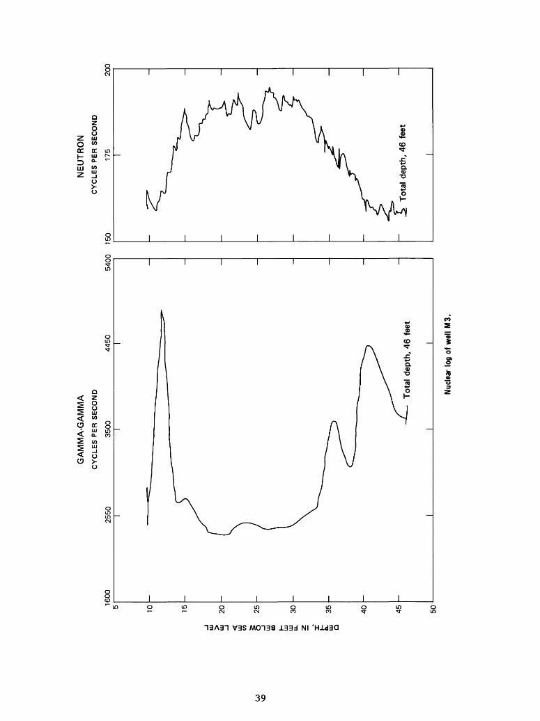
1600
10 15 20 25 30 35 40 45 50
2550
GA
MM
A-G
AM
MA
CY
CL
ES
PE
R S
EC
ON
D
3500
4450
5400
150
NE
UT
RO
N
CY
CLE
S P
ER
SE
CO
ND
175
200
Tot
al d
epth
, 46
fee
tT
otal
dep
th,
46 f
eet
Nuc
lear
log
of w
ell
M3.
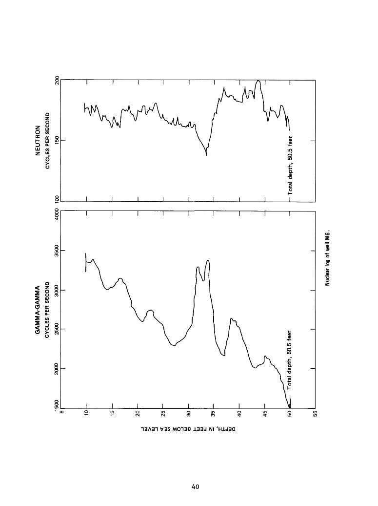
1500
10 15 20 25 30
£
35
a. UJ Q40 45 50 55
2000
GA
MM
A-G
AM
MA
CY
CL
ES
PE
R S
EC
ON
D
25
00
3
00
03500
40
00
10
0
NE
UT
RO
N
CY
CL
ES
PE
R S
EC
ON
D
150
20
0
To
tal
dept
h, 5
0.5
feet
- T
otal
dep
th,
50.5
fee
t
Nuc
lear
log
of w
ell M
6,

DEPTH, IN FEET BELOW SEA LEVEL
S Oo >- i CO 2
01
bii > O
CO CO
8
o o m z OT m o r-m S3» II

p-
fo
1500
10 15 20 25 30
5i
35
O
40 45 50
GA
MM
A-G
AM
MA
CY
CL
ES
PE
R S
EC
ON
D
2250
3000
3750
100
NE
UT
RO
N
CY
CL
ES
PE
R S
EC
ON
D
150
20
0
Tot
al d
epth
, 46
fee
tT
ota
l de
pth,
46
feet
Nuc
lear
log
of w
ell
S7.

20
00
10 15 20 25 30 35 40 45 50
GA
MM
A-G
AM
MA
CY
CLE
S P
ER
SE
CO
ND
5250
85
00
10
0
NE
UT
RO
N
CY
CLE
S P
ER
SE
CO
ND
125
150
Tota
l de
pth,
46
feet
Tot
al d
epth
, 45
.5 f
eet
Nude
ar lo
g of
wel
l S10
.

2000
5 10 15 20 25 30
uj
35
O
40 45
50
GA
MM
A-G
AM
MA
CY
CLE
S P
ER S
EC
ON
D
2450
2900
17
5
NE
UT
RO
N
CY
CL
ES
PE
R S
EC
ON
D
200
225
Tot
al d
epth
, 47
fee
tT
otal
dep
th,
47 f
eet
Nuc
lear
log
of w
ell
S12
.

2020
5 10 15 20 25 30 35 40 45 50 55 60 65
GA
MM
A-G
AM
MA
CY
CLE
S P
ER
SE
CO
ND
2470
2920
3370
150
NE
UT
RO
N
CY
CLE
S P
ER
SE
CO
ND
175
200
70
Tot
al d
epth
, 66
fee
t
I____________I Nuc
lear
log
of w
ell
S13.

2020
10 15 20
25
30
35
40
45 50
GA
MM
A-G
AM
MA
CY
CLE
S P
ER
SE
CO
ND
2470
2920
150
NE
UT
RO
N
CY
CLE
S P
ER
SE
CO
ND
175
200
Tot
al d
epth
, 50
fee
t
55
To
tal
dept
h, 5
0 fe
et
Nuc
lear
log
of
wel
l S1
4.
Ul
(O I Ul m UJ ui
u.
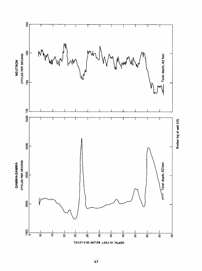
1000
5 10 15 20 25 30 35 40 45 50 55 60
2000
GA
MM
ArG
AM
MA
CY
CL
ES
PE
R S
EC
ON
D
3000
4000
5000
10
0
NE
UT
RO
N
CY
CL
ES
PE
R S
EC
ON
D
150
200
250
Tot
al d
epth
, 6
2 fe
et
65
To
tal
dept
h, 6
2 f
eet
I___________I
Nuc
lear
log
of w
ell
S15.

00
2000
10 15 20 25 30 35 40 45 50
2450
GA
MM
A-G
AM
MA
CY
CLE
S P
ER
SE
CO
ND
2900
3350
3800
15
0
NE
UT
RO
N
CY
CL
ES
PE
R S
EC
ON
D
175
200
225
Tot
al d
epth
, 4
8 f
eet
Tot
al d
epth
, 47
fee
t
I__
__
__
__
__
__
I
Nuc
lear
log
of
wel
l S1
6.
VD
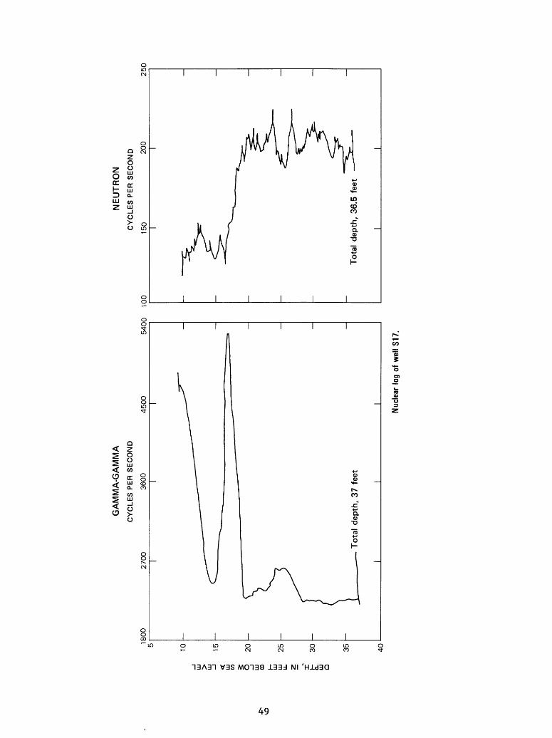
1800
10 15 20 25 30 35 40
2700
GA
MM
A-G
AM
MA
CY
CLE
S P
ER
SE
CO
ND
36
00
4500
54
00
100
NE
UT
RO
N
CY
CLE
S P
ER
SE
CO
ND
150
20
02
50
T
ota
l depth
, 37
feet
To
tal
depth
, 36.5
feet
__
__
__
I__
__
__
__
__
__
I
Nuc
lear
log
of w
ell
S17
.

APPENDIX B. - Drawdown data for 16 extraction test,September 24, 1980, beginning at 0936 hours
[t=time, in minutes; r=distance from pumped s=drawdown, in feet]
S14 Deep S14 ShallowTime r=55
t/r2
0.1.2.3.4.5.6.7.8.9
1.01.52.53.55678910.25152535.5455562708090100200300400500650750850
1,0001,2001,5001,560
3.36.69.91.31.62.02.32.63.03.35.08.31.21.72.02.32.63.03.45.08.31.21.51.82.02.32.63.03.36.69.91.31.72.12.52.83.33.94.95.2
X
X
X
X
X
X
X
X
X
X
X
X
X
X
X
X
X
X
X
X
X
X
X
X
X
X
X
X
X
X
X
X
X
X
X
X
X
X
X
X
io" 510~ sio" 510~ 4io"4io"4io" 4io"" 4io" 4io"4IO" 4io" 4io" 3io" 3io" 3io" 3io" 3io" 310~ 3io~ 3io" 3io" 2io" 2io" 2io" 2io" 2io" 2io" 2io" 2io"* 2io" 2io" 1io" 1io" 1io" 110" !io" 110" !io" 1io" 1
s
0.01.03.05.06.08.09.10.12.13.14.17.22.24.29.31.33.34.36.37.42.49.54.57.60.61.63.65.67.68.77.83.87.89.93.95.97.99
1.001.03
r=55
s
0.00.00.00.00.00.00.00.00.00.00.00.01.02.03.03.04.04.05.05.08.11.15.17.19.21.23.25.26.28.37.41.44.46.51.52.54.56.57.60
well, in feet;
Ull
t/r
2.5 x5.0 x7.5 x1.0 x1.3 x1.5 x1.8 x
2.5 x3.8 x6.3 x8.8 x1.3 x1.5 x1.8 x2.0 x2.3 x
3.8 x6.3 x8.8 x1.1 x1.4 x1.6 x1.8 x2.0 x2.3 x2.5 x5.0 x7.5 x1.001.251.631.882.132.503.003.75
r=20
2
io" 4io" 4io" 4io"3io"3io" 3io"3
io"3io" 3io" 3io"3io" 2IO"2IO" 2io" 2io" 2
io"2io" 2io" 2io" 1io" 1io" 1io" 1io" 1io" 110" iio" 110" i
16 Pumped wellr=l
s
0.07.11.17.21.23.26.28
.32
.38
.45
.48
.52
.53
.55
.57
.58
.65
.72
.77
.80
.83
.84
.86
.88
.89
.911.001.051.081.161.201.231.251.261.281.30
t/r
0......m
9
.11.2.3.56789
10.152535.455562708090100200300400500650750850
1,0001,2001,5001,560
2
1
23456789
555
25
5
s
0.28.40.50.57.62.65.69.71.74.75
.89
.93
.971.001.021.031.051.071.121.201.231.261.291.311.331.351.361.381.471.521.561.571.621.641.661.671.691.711.72
50