Embed Size (px)
Citation preview
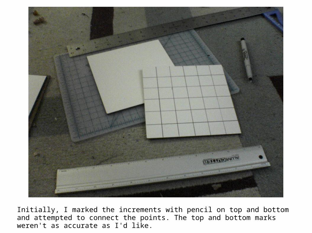
Initially, I marked the increments with pencil on top and bottom and attempted to connect the points. The top and bottom marks weren't as accurate as I'd like.

Next I attempted to draw the line by eyeballing the alignment and making fine adjustments against the t-square by moving the t-square around.

This was working okay, but it still wasn't as consistent as I wanted – there were also line mistakes from my hand slipping or needing to retrace part of a line.

After the second block, I decided to try a systematic approach. First I taped the board to the cutting mat grid with masking tape.

Next, I taped the t-square ruler to the bottom in alignment with block.
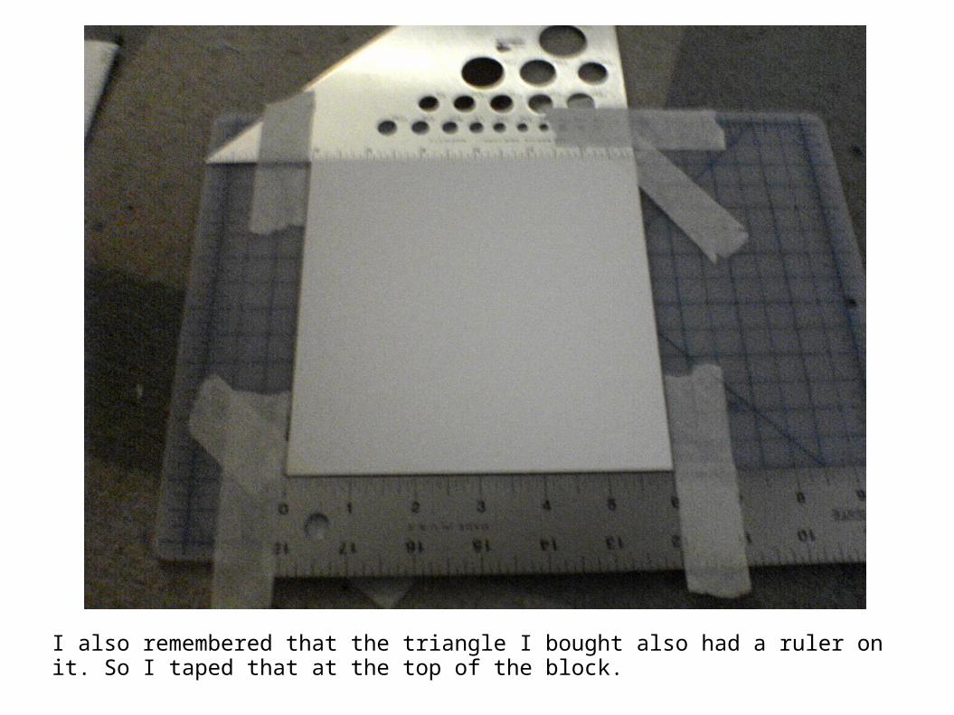
I also remembered that the triangle I bought also had a ruler on it. So I taped that at the top of the block.

Next I laid my backed ruler on the block itself and aligned it with the two reference rulers to produce a more consistent grid.

I also added masking tape over the ruler to prevent marking the ruler itself so I didn't have to be as hesitant drawing my lines.

This method proved to be more consistent than the first two.

Next I removed the rulers rotated the mat, and reset the rulers and began on the bisecting lines.

The previous block was better, but I was having issues with line consistency. So I tested the pen on some paper to make sure it was in fact my stroke and not the pen itself before beginning the next block.

For the last block, I closed one eye while I drew the lines to ensure ruler alignment and prevent drawing errors from paralax.

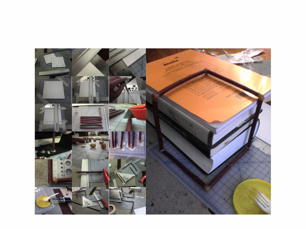
Next, I sized up the sticks and the stones of the cutting mat.
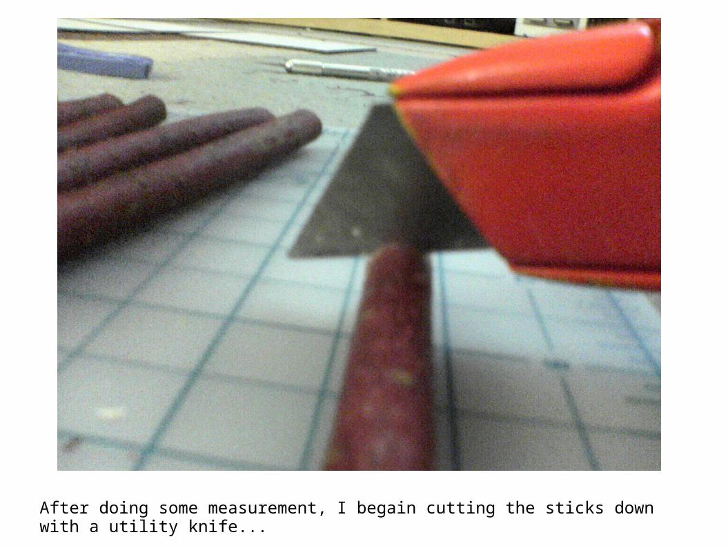
After doing some measurement, I begain cutting the sticks down with a utility knife...
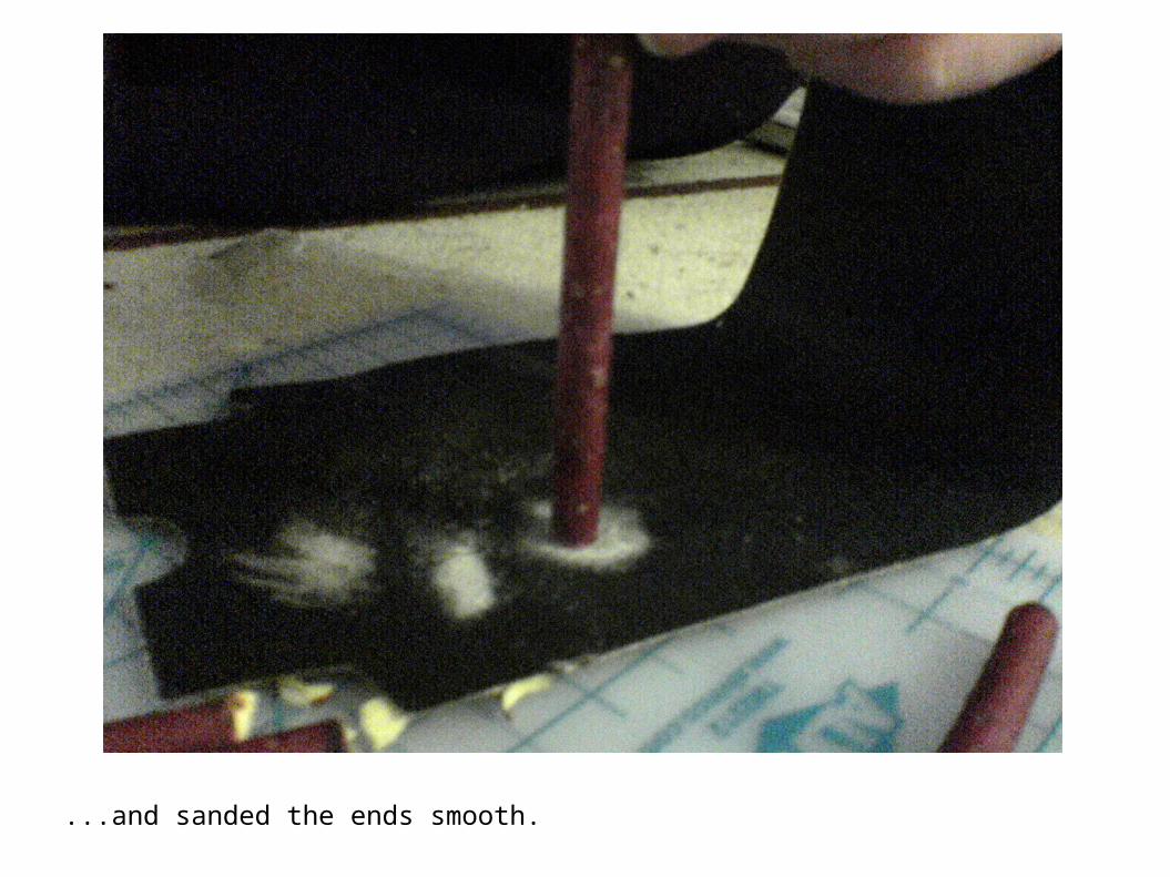
...and sanded the ends smooth.

First I just cleaned one end of each stick.

Next I used epoxy to attach one stone to the end of each of the sticks.
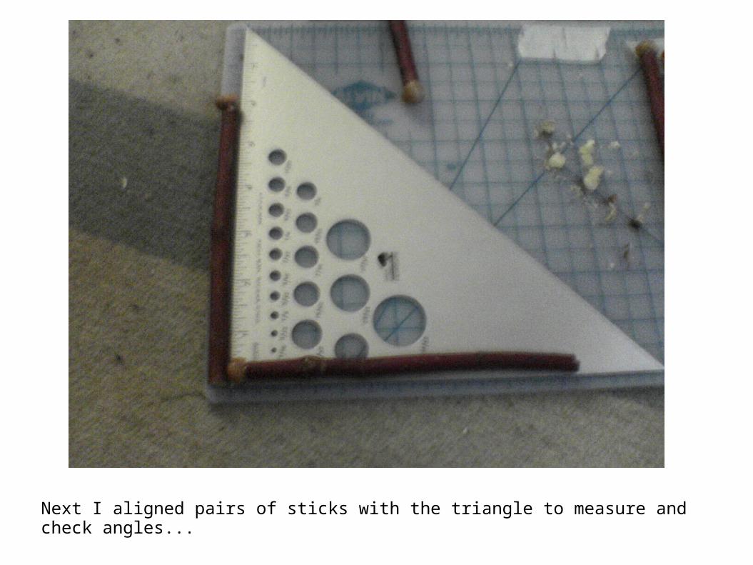
Next I aligned pairs of sticks with the triangle to measure and check angles...

Measure the stone length against the stick it was to be joined to...

Then make the cuts...

...which was really more sawing with a dull blade than cutting. More sanding.

Once the first pair of L's were trimmed, I glued them with epoxy and let them dry a bit.
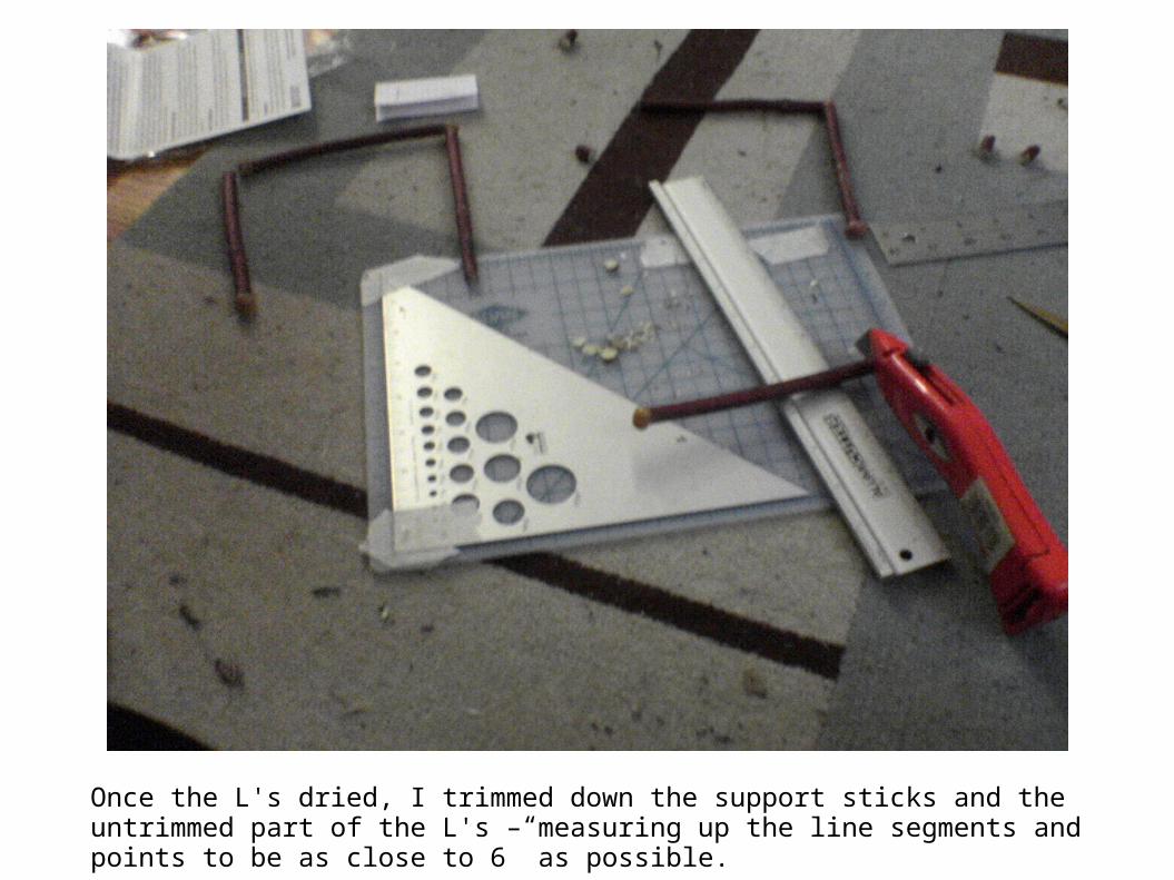
Once the L's dried, I trimmed down the support sticks and the untrimmed part of the L's – measuring up the line segments and points to be as close to 6” as possible.

Once the other pieces were trimmed, I applied epoxy and taped the support sticks with masking tape on to a book to hold them in place while they dried.
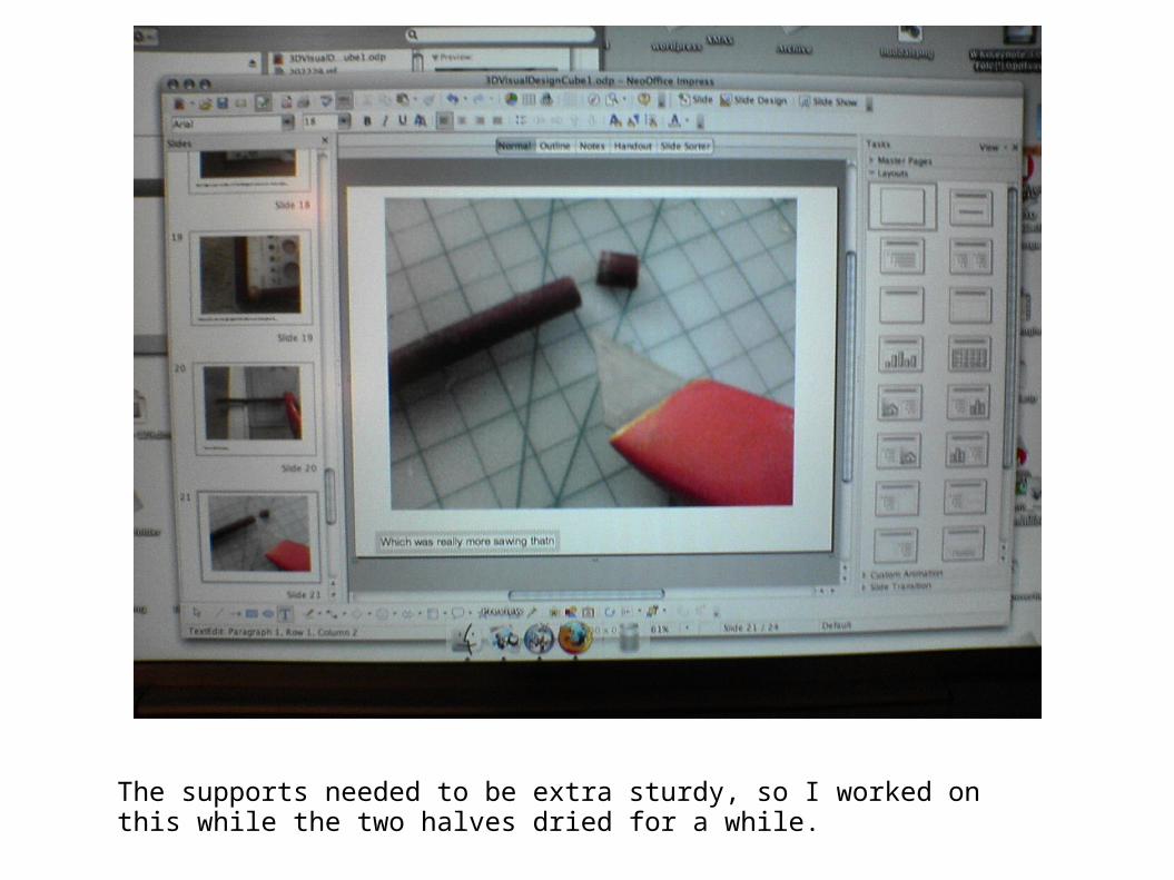
The supports needed to be extra sturdy, so I worked on this while the two halves dried for a while.

MORE EPOXY! Chances are I can still smell it while I'm reading this.

Finally I secured the two halves together with said epoxy. The top half was supported by books while it dried.
Last but not least, I attached the mostly dried frame to a base with more epoxy and left the structure to dry over night.

CTRichadson Project 2:
FIBOCUBI

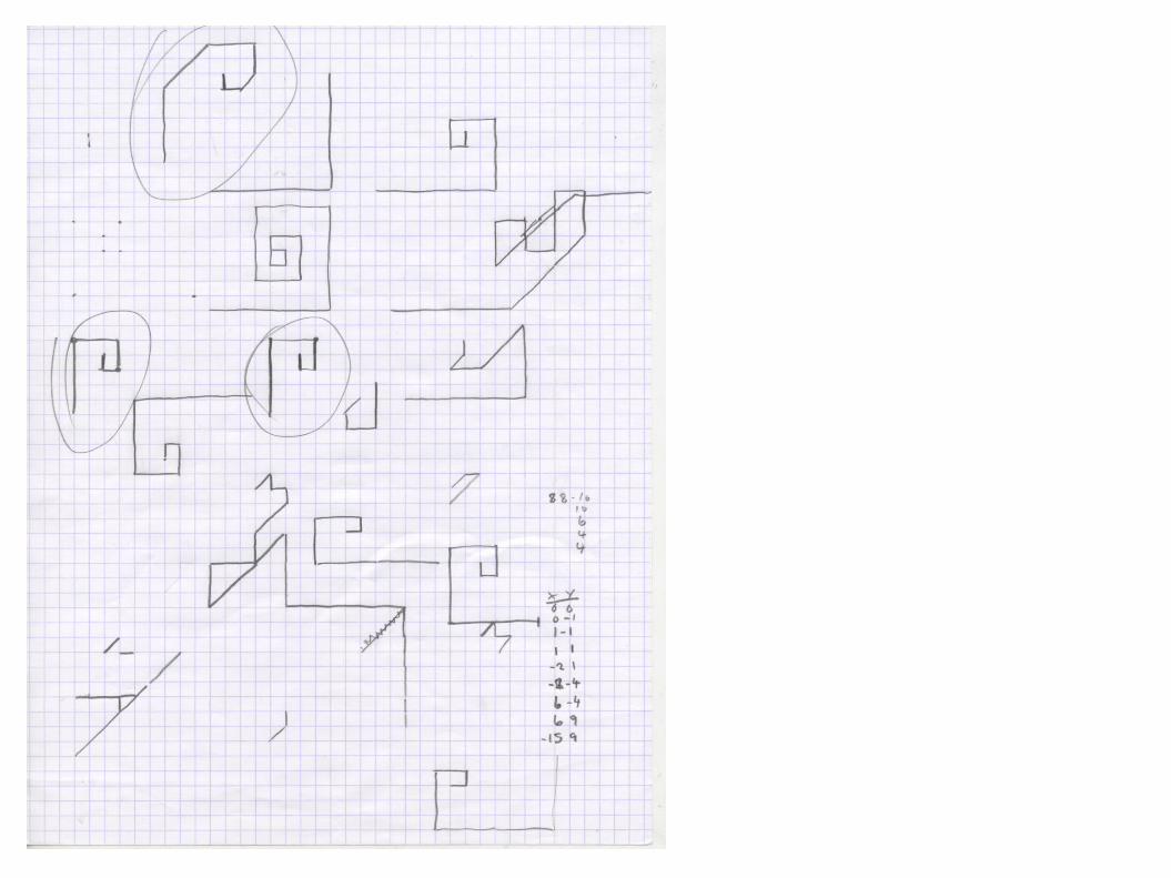
I decided to document my design thoughts as best I could in design notes along with my drawings.
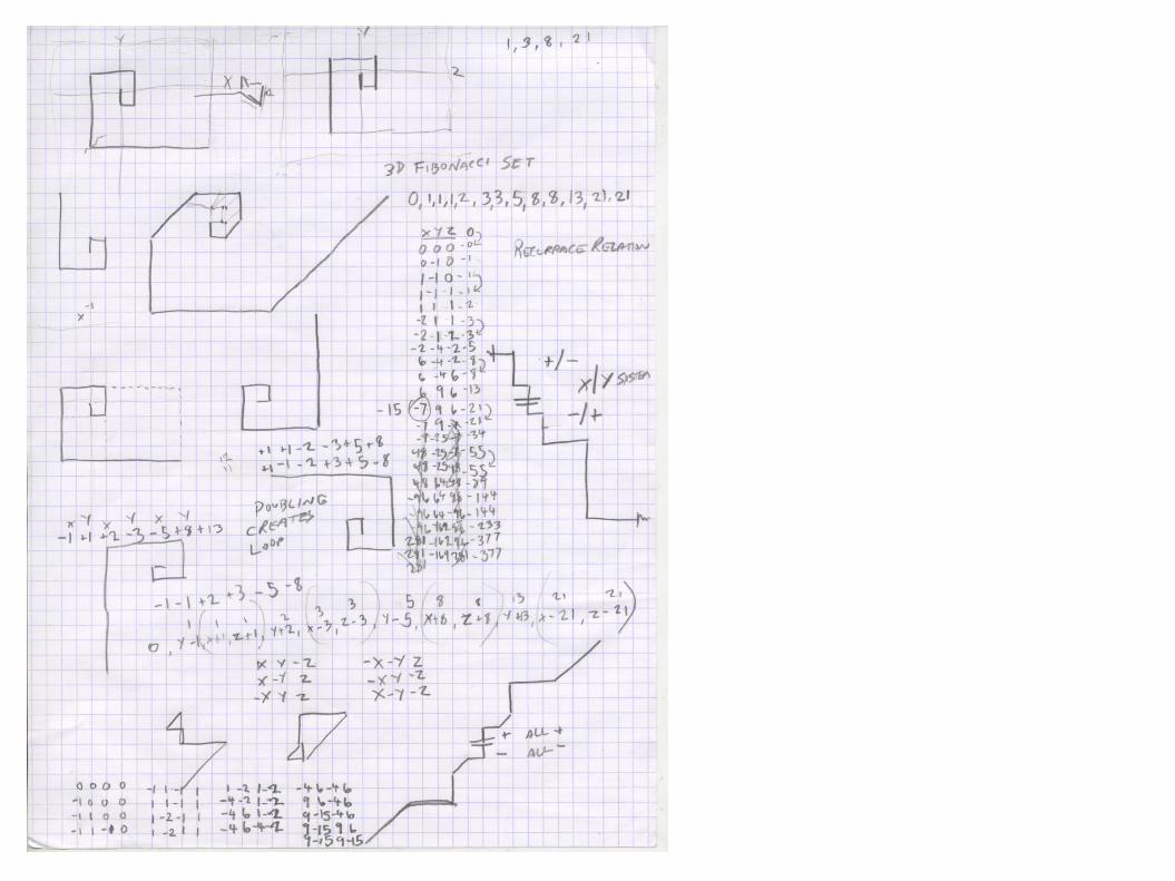
Initially I was attempting to create a straight representation of plotted Fibonacci line segments. I thought I had found a solution for a while, but upon building the model in a 3D application, I realized that only the front/side/back views presented the same pattern, while the top and bottom views were different. After extrapolating points in space to represent the structure, I realize that the form I as initially looking for was only possible to create in four dimensional space, making creating a literal physical model of it highly unlikely.

Additional drawings working towards the final format and experimenting with the previous form from different perspectives.
Getting closer, more experimentation.
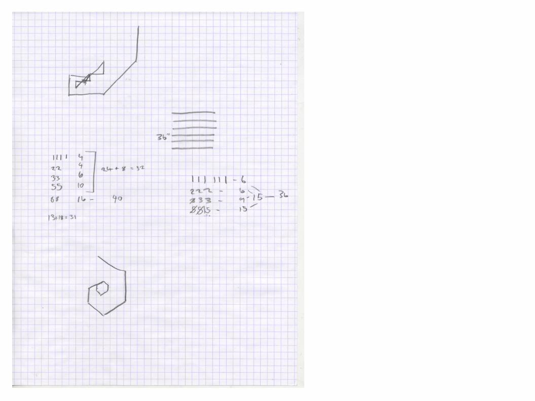
Determining stick lengths and the final form.

Trimming sticks down to designated lengths.
Laying out 2D pattern.
Lining sticks up to cut angles.
Trimmed sticks and vertical sticks.

Gluing sticks together with epoxy.
Final gluing.

Challenges:I had difficulty keeping the angles flush, and gluing the central cube structuretogether proved to be very difficult. I also misjudged the amount of stick I had,which certainly could have been avoided. Cutting the angles proved to be verydifficult but was made easier with a 3d model reference.


CTRICHARDSON Final Presentation

CUBE1::6 Line 6 Point Cube Form

CUBE1::GOALSWhen approaching the design of my original cube, I wanted to establish the form of a cube using the sticks as line segments and the stones as end-points. I wanted to maximize the cube like nature of the form, while remaining within the constraints of the assignment. It was also important to me to focus on the craft of the physical model construction.

CUBE1::INITIAL SKETCHESWhile my original sketching was some-what limited, as I quickly arrived at my desired form. My final form was the inverse of the original form that I had intended. My choice to modify the form was based on material considerations, but is actually the stronger design of the two.
CUBE1::CONSTRUCTION

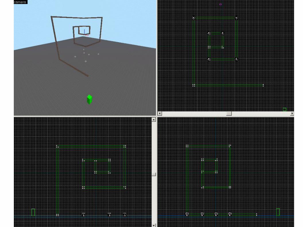
CUBE1::FINAL RENDERINGS

CUBE1::CONCLUSIONSOverall I am pleased with the results of CUBE1. I feel that the original design is the best design possible to capture the notion of a cube with the designated materials and restrictions. I am also pleased with the resulting model that I produced. The form provides identical square views in plan and strongly suggests a cube in the third dimension.

CUBE2::Fibocubi

CUBE2::GOALSAfter completing the original cube, I wanted to work with a Fibonacci number set in order to derive the form of my second cube. My goal was to determine and build an ideal Fibonacci based model representing both 2D planar and 3D Fibonacci escalations. Can it be done? If so, how? I also wanted to focus again on construction craft and to utilize 3D modeling in order to create a reference representation. It was also more important to make more documentation of the actual design process.

CUBE2::INITIAL SKETCHES
I did a lot of sketching while attempting to grasp the 3D form I was looking for. At one point I believed that I had found it, but on deriving the points that made up the form realized I was in error, but I also realized that the exact form I was initially looking for wasn’t possible in 3D space - requiring a 4th spacial dimension for symmetry.

CUBE2::CONSTRUCTION
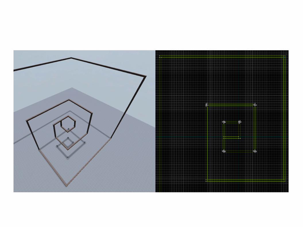
CUBE2::FINAL RENDERINGS

CUBE2::CONCLUSIONSCUBE2 ended up being an evolution of cube 1, entirely by chance. The end solution of tripling Fibonacci numbers to represent each axis and alternating negative and positive values for for each triplet constructs a cube form identical to CUBE1 at it’s core. From there, the Fibonacci numbers make the cube grow ever outward. I tried a different technique to construct the joints of the physical model for CUBE2 by cutting 45 degree angles at the ends of the line segments, and it made the job much more difficult. However, the joints do look very nice. It also achieves it’s goal of providing identical plan views from each side and suggesting an expanding cube in the third dimension.


![[ACM-ICPC] Top-down & Bottom-up](https://img.dokumen.tips/doc/110x75/555602efd8b42a8a5f8b55b0/acm-icpc-top-down-bottom-up.jpg)


