Embed Size (px)
Citation preview

Ingersoll COMPACT TRACTORS
301230143016 3018 3018PS 4016 4020 4020PS
Operators Manual 8 -59130
QUALITY IN THE AMERICAN TRADITION
Ingersoll Equipment Co Inc Winneconne Wisconsin 54986-9576
IF THIS MACHINE IS USED BY AN EMPLOYEE OR IS LOANED OR RENTED MAKE ABSOLUTELY CERTAIN TILT THE OPERATOR(S) PRIOR TO OPERATING
1 IS IJSTRUCTED IN SAFE ND PROPER USE
~ REVIEWS AND UNDERSTANDS THE Y1ANUAL(S) PERTINING TO TIlE 1(IIINE
7gt 12 53
BEFORE STARTING ENGINE STUDY OPERATORS MANUAL SAFETY MESSAGES
READ ALL SAFETY SIGNS ON MACHINE CLEAR THE AREA OF OTHER PERSONS
LEARN amp PRACTICE SAFE USE OF CONTROLS BEFORE OPERATING
II IS YOUR RESPONSBIL I Y 10 UNLJpound R S I AND AND FOLLOW MANUF AC 1 uRE RS INS 1 Rue IONS O N MACHINE O PERATION S ERVICE AND 10 OBSERVE PERTINENT LAwS AND REGULAIION S OPERATOR ANO SERVICE MANUAL S MAY BE OBTAINED FROM YOUR EQUIPMENT DEALER
WARNING The engine exhaust from this product
contains chemicals known to the State
of California to cause cancer birth
defects or other reproductive harm
TABLE OF CONTENTS
SAFETY MESSAGES II - VII TO THE OWNER 2 PRODUCT IDENTIFICATION (PIN) OR SERIAL NUMBERS (SIN) 3 OPERATING INSTRUCTIONS 4-12
Operating Controls and Instruments 4 -7 Prestarting Check List 8 Break-in Procedure 8 Starting Procedure 9 Stopping Procedure 10 Operating Procedure 11-1 2
TROUBLESHOOTING GUIDE 13 PREVENTIVE MAINTENANCE 14-30
Maintenance Chart 15 Capacities 15 Specifications 16-1 7 Over All Measurements 17 Wiring Diagrams 18-20 Storage Battery 21 Jumper Cables and Booster Battery 22 Headlights 23 Fuse 23 Attachment Drive Clutch Break-in Procedure 23 Brake 24 Fuel 25 Hydraulic Oil 26 Hydraulic Oil Cooler 27 Hydraulic Oil Filter 27 Seat 28 Transaxle 28 Chassis Lubrication 29 Steering Adjustment 30 Toe-in Adjustment 30
MANUAL ORDERING PROCEDURE 31
SAFETY MESSAGES
CAUTION DisengageThe f irst twenty-five safety messages which follow power to attachment(s) whenare provided by the American National Standards transporting or not in useInstitute (ANSI) Safety rules to supplement those A
provided by ANSI also appear on the following pages
Study these rules carefully before starting and operating your Lawn and Garden Tractor
A Separate Operators Manuals are provided with the attachshyments purchased with your tractor Refer to the approshypriate attachment operators manual for specific operating instructions and safety messages that apply to the attachment
A CAUTION Know the controls and how to stop quickly READ THIS OPERATORS MANUAL and instructions furnished with attachments
A CAUTION Do not allow childshyren to operate the machine Do not allow adults to operate it without proper instruction
A CAUTION Do not carry passhysengers Do not mow when children and others are around
A CAUTION Clear the work area of objects (wires rocks etc) that might be picked up and thrown
A CAUTION Disengage all atshytachment clutches and shift into neutral before attempting to start the engine (motor)
A CAUTION Disengage power to attachment(s) and stop the engine (motor) before leaving the operators position
A CAUTION Disengage power to attachment(s) and stop the engine (motor) before making any repairs or adjustments
A
A A A A
A
CAUTION Take all possible precautions when leaving the vehicle unattended such as disengaging the power takeshyoff lowering the attachment (s) shifting into neutral setting the parking brake stopping the engine and reshymoving the key
CAUTION Do not stop or start suddenly when going upshyhill or downhill Mow down the face of steep slopes never across or up the face (This ANSI rule modified)
CAUTION Reduce speed and exercise extreme caution on slopes and in sharp turns to prevent tipping or loss of conshytrol Be especially cautious when changing direction on slopes
CAUTION Stay alert for holes rocks and roots in the terrain and other hidden hazshyards Keep away from dropshyoffs
CAUTION Use care when pulling loads or using heavy equipment a Use only approved drawshy
bar hitch points
b Limit loads to those you can safely control
c Do not turn sharply Use care when backing
d Use counterweights or wheel weights when suggested in this opershyators manual
CAUTION Watch out for traffic when crossing or near roadways
II
CAUTION When using any
A CAUTION Do not change
attachments never direct disshy the engine governor settings charge of material toward byshy or overspeed the engine standers nor allow anyone near the vehicle while in opershy
A A
ation
CAUTION Handle gasoline with care - it is highly flamshymable
a Use approved gasoline container
b Never remove the fuel cap of or add gasoline to a running or hot engine or an engine that has not been allowed to cool for several minutes after running Never fill the tank indoors and always clean up spilled gasoline
c Open doors if the engine is run in the garage - exshyhaust fumes are dangershyous Do not run the enshygine indoors
CAUTION Keep the vehicle and attachments in good operating condition and keep safety devices in place and in working condition
CAUTION Keep all nuts bolts and screws tight to be sure the equipment is in safe working condition
CAUTION Never store the equipment with gasoline in the tank inside a building where fumes may reach an open flame or spark Allow the engine to cool before storing in any enclosure
CAUTION To reduce fire hazard keep the engine free of grass leaves or excessive grease
CAUTION The vehicle and attachments should be
A A
CAUTION When using the vehicle with mower proceed as follows
11) Mow only in daylight or in good artificial light
12) Never make a cutting height adjustment while the engine (motor) is running if the operator must dismount to do so
13) Shut the engine (motor) off when removing the grass catcher or uncloggshying chute
(4) Check the blade mounting bolts for proper tightness at frequent intervals
CAUTION Under normal usage the grass catcher bag material is subject to deteriorshyation and wear Check bag frequently for deterioration and wear and replace worn bags Check that replacement bags comply with the original manufacturers recommendshyations or specifications
CAUTION Disengage power to mower before backing up Do not mow in reverse unless absolutely necessary and then only after observation of the entire area behind the mower
CAUTION Do not wear loose clothing which may catch in moving parts
CAUTION Do not smoke when working near fuel
A stopped and inspected for damage after striking a foreign object and the CAUTION Drive at a speed
slow enough to insure safetydamage should be repaired before restarting and and complete control at all
timesoperating the equipment
III
A CAUTION Highway travel should be avoided If necshyessary use SMV safety emblem and lights for adequate warning to the operators of other vehicles Check local government regshyulations
A WARNING Improper operation of your tractor on hillsides and slopes can be dangerous Avoid improper operation Read and follow the instructions given in the section titled Hiside Operation in this manual
A
A
CAUTION Read operators manuals
Know location and function of all controls
Keep all shields and safety switches functional
Before starting engine disengage attachment drive and place travel control in neutral
Remove objects from the terrain that could be thrown by the attachment
Keep people and pets a safe distance away
Never carry passengers Always look behind tractor
before backing On any incline that the
tractor can be safely operated use low rangegear
Front end tip over can occur when operating on loading ramps or hills back up ramps or hills
Drive forward going down ramps or hills
To park tractor place travel control in neutral set parking brake disengage attachment drive shut engine off and reshymove key
Park tractor before sershyvicing or making adjustments to tractor or attachments
Failure to observe these precautions could result in serious injury or death
CAUTION Place the transmission in neutral set the parking brake and stop the engine before standing between the tractor and attachment when hitching
A A
A
A
before opera~ing your tractor
CAUTION If necessary to move tractor on a trailer al shyways back up onto the trailer and drive off of trailer
CAUTION Hydraulic sysshytems are highly pressurized Escaping hydraulic oil even an invisible pinhole leak can penetrate body tissues causing serious injury Use a piece of wood or cardboard when looking for leaks - never use the hands or other parts of the body
Relieve hydraulic pressure before disconnecting circuits When reassembling make absolutely certain that all conshynections are tight
If injured by hydraulic oil escaping under pressure see a doctor immediately Serious complicaitons may arise if medical attention is not given at once
CAUTION When adjusting steering wheel free play make certain that some free play remains between the sector gear and pinion gear since a tight fit with no clearance beshytween the two gears may cause binding and tooth fail shyure
CAUTION When removing a battery always disconnect the 1-) negative ground cable first When installing the battery always connect the 1-) negative ground cable last
CAUTION Storage areas for Become thoroughly familiar batteries must be well ventil shywith all tractor and attachshy ated to prevent accumulation ment controls before of hydrogen gas from newly operating recharged batteriesA A
IV
DANGER Batteries produce explosive charges Keep sparks flame and cigarettes away Ventilate when chargshying or using in enclosed space Always shield eyes when working near batteries
CAUTION When working around storage batteries reshymember that all of the exshyposed metal parts are live Never lay a metal object across the terminals as a spark or short circuit may result Sparks lighted matches and exposed flames must be kept away from the battery due to the presence of explosive gas in the battery The liquid in the batteries is acid Use care not to spill it on hands or clothing
POISON Batteries contain sulfuric acid which can cause severe burns Avoid contact with skin eyes or clothing Antidote EXTERNAL flush with water INTERNAL drink large quantities of water or milk Follow with milk of magnesia beaten egg or veg shyetable oil Call physician imshymediately EYES flush with water for 15 minutes and get prompt medical attention Keep out of reach of children
Remember a careful operator is always the best insurance against an accident Give complete and undivided atshytention to the job at hand
CAUTION Set parking brake shut off engine remove key and wait until all engine and attachment motion has stopped before dismounting from the operators seat
WARNING To jump start this machine connect posshyitive jumper cable to battery terminal on starter solenoid and connect negative jumper cable to good engine ground Start engine only when seated in operators seat Stop enshygine before leaving machine Disconnect jumper cables Any other method could result in uncontrolled machine movement
CAUTION Never wear rings or metal watch bands when working with the tractor electrical system or battery as you may ground a live circuit
CAUTION Too much air pressure in the tires can cause tire or rim failure Never put more air pressure in a tire than specified in the operators manual or on the sidewall of the tire If the tire or rim explode because of too much pressure injury can result
CAUTION Before attemptshying to service the attachment Drive Clutch be sure to remove tractor key and spark plug wire(s)
CAUTION Only operate controls from the operators seat to prevent injury
IMPORTANT Always install new decals whenever the old decals are destroyed lost painted over or illegible When individual parts are replaced that have decals attached be sure to install a new decal with the new part Replacement decals are available from your dealer
CAUTION Do not operate machine while under the influence of alcohol or drugs
v
HILLSIDE (SLOPE) OPERATION
Read Understand ObeyWARNING Improper operashytion of your tractor on hill shy
A sides and slopes can be danshygerous Avoid improper opershyation Read and follow the inshystructions given in the section titled Hillside Operation in this manual before operating you r tractor
Avoid operating tractor on hillsides and slopes To minimize the possibility of accidents while operating on hills andor rough terrain obey a combination of rules practices and good common sense
These include
1 Reading understanding and obeying all written safety messages appearing on decals on the mashychine and in operators manuals
2 Learning from your operators manual and carefulshyly from EXPERIENCE how to operate your tractor correctly Know your tractors limitations
3 Knowing the terrain on which you are operating your tractor There are terrain conditions on which your tractor cannot be operated
4 Learning to expect changes in operating condishytions Adding or removing attachments or weight to your tractor will make your tractor perform difshyferently Rain snow loose gravel wet grass etc change the tractive conditions of the terrain reshyquiring changes in your operating technique or not to operate on that terrain
The following paragraphs will cover these practices one at a time Read and study them The examples provided are not all inclusive but will give you a firm understanding of the requirements for avoiding accishydents while operating your tractor
Ingersoll Lawn and Garden Tractors are designed and built to comply with the Voluntary Standard ANSI
(American National Standards Institute)
THE OPERATOR IS THE SOLE JUDGE AS TO THE DEGREE OF SLOPE ON WHICH THIS TRACTOR CAN BE SAFELY OPERATED IF IN DOUBT THAT THIS TRACTOR CAN BE SAFELY OPERATED ON A PARTICULAR SLOPE DO NOT OPERATE ON THAT SLOPE COMMON SENSE MUST PREVAIL
VI
Safety messages are found on the tractor and in the operators manuals These must be understood by the tractor operator to be of value Be sure that these messhysages are studied before starting andor operating the tractor by an operator not familiar with this particular tractor
learn to Operate
Learn your tractors controls from decals on the tracshytor and from instructions in the operators manual Practice how to properly manipulate these controls Practice must be done in a flat area clear of obstacles and bystanders Learn your tractors operating characshyteristics and limitations These include
a amount of engine power available
b engine governor response
c tractive ability
d steering characteristics
e braking characteristics
f movement of travel lever
g forward and reverse ground speeds
h speed of attachment lift
i and others
Attempting any operation which approaches or exshyceeds the tractors limitation is risking an accident
Know the Terrain
Know the terrain on which you are working Find hidshyden obstacles by walking through and inspecting the area prior to operating your tractor on it Mark obshystacles such as rocks ruts or holes with a 6 ft long pole and red flag and stay well clear of these obstacles when operating
Operate your tractor at a ground speed slow enough to insure complete control at all times
Place the transmission in low gear and regulate the throttle control lever slowly and smoothly to maintain this safe speed Do not stop on a hill or slope to change gears
-Always drive in a forward direction when proceeding downhill Never drive up a hill If necessary back up a hill to the desired position Always back up loading ramps and tilt bed trailers If necessary to turn while on a hill always turn downward
Your judgement based on operating experience is the final word in deciding if you should negotiate any given hill or slope If you are in doubt about safety ST A Y OFF THE SLOPE
Under no circumstances should an inexperienced opshyerator attempt to use your tractor on slopes or hillshysides
You may encounter some terrain on which your tracshytor cannot be operated even if a different piece of equipment has operated there in the past
Learn to Compensate for Changes in Operating Conditions
Adding or removing attachments or ballast (such as wheel weights or fluid) change the weight and weight distribution of your tractor and therefore changes your tractors operating characteristics
Be alert to these changes Practice operating the tracshytor after each change has been made
Adding an attachment (weight) to the rear of the tracshytor reduces the weight on the front axle Adding an atshytachment (weight) to the front of the tractor reduces weight on the rear of the tractor You must add counshyterweight to the front if a rear mounted attachment is installed You must add counterweight to the rear if a front mounted attachment is installed
Tractive conditions will vary with weather and terrain and equipment
Areas wet with dew or rain will be more slippery than when dry Areas covered with loose gravel are more slippery than firm dry ground Greater stopping disshytances are required in these slippery areas
Spinning rear wheels tend to move the tractor sideshyways The addition of tire chains will provide more traction to the rear wheels in the forward-reverse dishyrection but less stability in the sideways direction Chains will cause more abrupt starting and stopping
The final word in safe tractor operation rests on your judgement
If in doubt of your safety STAY OFF THE SLOPE
VII
FIGURE 1
1
TO THE OWNER
The Maintenance you give your new tractor is imporshytant Use this manual as your guide Follow these instructions and tips to make sure your tractor opershyates efficiently for many years
We are a factory authorized dealer We have replaceshyment parts which are the same as the original equipshyment
If you need additional aid or information contact us
CY()tMt ~ 9eak
NOTE Ingersoll Equipment Co Inc reserves the right to make improvements in design or changes in specifications at any time without incurring any obligation to install them on units previously sold
IMPORTANT This manual covers many different NOTE model tractors The illustrations usshy
ed in this manual may not be of your tractor
NOTICE
A spark arrester or spark arrester muffler must be used on some machines Check the laws in your area
Some states have regulations for the use of this mashychine in agriculture forestry and construction These laws control the maintenance of spark arrester equipshyment These laws also control the installation of spark arrester equipment on the exhaust system of naturally aspirated engines (engines without a turbocharger)
RADIO INTERFERENCE REGULATIONS OF CANADA
Tractors taken into Canada after September 1 1976 must have resistor spark plugs
Resistor spark plugs and resistor wires for the spark plug must be used for replacement
Printed in USA 10-96-RP-1000-119
- -------
PRODUCT IDENTIFICATION NUMBER (PIN) OR SERIAL NUMBER
When you need parts or information or when you write to your authorized dealer always give the For reference write the numbers below
1 Tractor Model Number
2 Tractor Product Identification Number (P1 N)
3 Engine Model Number
4 Engine Serial Number
5 Engine Specification Number
ENGINE MODEl SERIAL AND SPECIFICATION NUMBERS
ONAN ENGINE FIGURE 3
TRACTOR MODEl AND PRODUCT IDENTIFICATION NUMBER
FIGURE 2
This manual is for the following compact tractors
MODEl 3012 PIN 14145700 and after 3014 PIN 14146700 and after 3016 PIN 14147800 and after 3018 PIN 14181200 and after 3018PS PIN 14181900 and after 4016 PIN 14170800 and after 4020 PIN 14176500 and after 4020PS PIN 14184000 and after
The words Right Left Front and Rear as used in this manual indicate directions when you are in the operators seat in the normal operating position
- 3 shy
ENGINE MODEL SERIAL AND SPECIFICATION NUMBERS
BRIGGS amp STRATTON ENGINE
FIGURE 4
OPERATING INSTRUCTIONS
NEUTRAL
THROTTLE
1 PARKING rlt
BRAKE ~ I
LOCK FFIGURE 5
OPERATING CONTROLS AND INSTRUMENTS
A CAUTION Know the controls The choke must be open during normal operation and how to stop quickly or when you start a warm engine READ THIS OPERATORS MANUAL and instructions
3 THROTTLEfurnished with attachments
A ENGINE LOW IDLE Pull the throttle leverBecome thoroughly familiar rearward Put the throttle in the SLOWpositionwith all tractor and attachshywhen starting and when stopping the engine This ment controls before permits a warming and cooling period operating
TO INCREASE ENGINE SPEED Push the throttle
A lever forward until the needed engine speed is
CAUTION Only operate reached controls from the operators seat to prevent injury Decrease the engine speed during operation for
maximum fuel efficiency Do not cause engine lugging Lugging will cause too much heat and
1 IGNITION KEY AND STARTER SWITCH damage to the engine
TO START Turn the key to the right and hold in the START position
CAUTION Do not changeTO RUN Release the key to the RUN position the engine governor settingswhen the engine starts or overspeed the engineA TO STOP Turn the key to the left to the OFF position
2 CHOKE 4 HEADLIGHTS
TO CLOSE THE CHOKE Push the choke lever TO ILLUMINATE Press the switch to illuminate forward Close the choke to start a cold engine the headlights
TO OPEN THE CHOKE Pull the choke lever rearward Open the choke slowly after the engine TO TURN OFF Press the switch to turn off the starts headlights
- 4 shy
5 BATTERY VOLTAGE INDICATOR LIGHT
The battery voltage indicator light will illuminate when the battery voltage is low and will go out when the battery voltage is acceptable
It is normal for the light to illuminate when the tractor is first started after a period of non-use and to glow when the tractor engine is operated at low idle speed
Stop the engine and have the problem corrected if the indicator light does not go out after running the engine at normal operating speed after a few minutes of operation
It is normal for the Battery Voltage Indicator light to remain out if the engine is stopped when the battery is fully charged and the ignition key is turned to the run position
6 HOUR METER
The electric hourmeter records hours of operation whenever the key is in the RUN position
Utilize the hourmeter to meet the required maintenance schedule
7 BRAKE PEDAL
TO ACTUATE THE BRAKE Push the brake pedal fully down
This action will return the travel control to the NEUTRAL position
The tractor will come to a quick stop
NOTE Do not use the above method if possible
Stop the tractor with the travel control lever
The tractor can be stopped smoothly by slowly returning the travel control lever to the NEUTRAL position
Actuate the brake fully if you can not stop the tracshytor with the travel control lever
See the Operating Procedure Section of this manual for a more complete description of stopping travel
8 PARKING BRAKE LOCK
TO ENGAGE Push the brake pedal fully down
Push down on the parking brake lock
TO DISENGAGE Push the brake pedal a small amount and release
A spring will disengage the parking brake lock
9 HYDRAULIC ATTACHMENT LIFT LEVER
TO LIFT Run the engine
Pull the lever rearward
Release the lever when the needed height is reached
TO LOWER Run the engine
Push the lever forward a small amount
Release the lever when the needed height is reached
When you release this lever a spring will autoshymatically return the lever to the NEUTRAL position
THE FLOAT POSITON Push the lever fully forshyward
A detent holds the lever in the FLOAT position The lever must be manually returned to the NEUTRAL position from the FLOAT position
The FLOAT position prevents hydraulic down pressure on the attachment
See the instructions included with each attachment for correct attachment lift lever use
10 ATTACHMENT DRIVE (PTO) SWITCH
TO ENGAGE Pull switch toggle out and push upshyward See Attachment Drive Clutch Break-in proshycedure in maintenance section in this manual before operating your attachment
The center dash panel indicator light will illuminate when the attachment drive switch is on
TO DISENGAGE Push switch down
The center dash panel indicator light will go out when the attachment drive switch is off
NOTE The attachment drive switch must be off before you can start the engine
- 5 shy
--shy - TRAVEl ~ CONTROL
LEVER DUAL RANGE TRANSAXLE
BRAKE
L
~=~PEDA~ ~~
FIGURE 6 EARLY STYLE RANGE SHIFT
~=JltL=_)JkI~~
i I~ HYDRAULIC
DUAL RANGE
f~~ ~~EVER
gt1~JTRANSAXLE
FIGURE 6A CURRENT STYLE RANGE SHIFT
11 DUAL RANGE TRANSAXLE (EARLY STYLE)
TO SELECT LOW RANGE Put the travel control lever in the NEUTRAL position
Stop the tractor
Pull the lever forward a small amount to go over the neutral locating pin
Pull the lever up beyond the neutral locating pin and release
TO SELECT NEUTRAL Put the travel control lever in the NEUTRAL position
Stop the tractor
Pull the lever forward a small amount to go over the neutral locating pin
Align the hole in the lever with the neutral locating pin and release the lever
TO SELECT HIGH RANGE Put the travel control lever in the NEUTRAL position
Stop the tractor
Pull the lever forward a small amount to go over the neutral locating pin
Push the lever down beyond the neutral locating pin and release
If the range shift does not move easily rotate the gears
To rotate the gears
1 move the travel control lever a small amount into the FORWARD position
2 return the travel control lever to the NEUTRAL position
IMPORTANT The range shift lever must be beyond the neutral locating pin while in LOW or HIGH range If the lever is not in the correct position damage to the gears will result
DUAL RANGE TRANSAXLE (CURRENT STYLE)
TO SELECT LOW RANGE Put travel control lever in NEUTRAL position
Stop tractor
Push lever down and to left Release lever up into LOW RANGE notch
TO SELECT NEUTRAL Put travel control lever in NEUTRAL POSITION
Stop tractor
Push lever down and move lever to align with NEUTRAL notch and release
TO SELECT HIGH RANGE Put travel control lever in NEUTRAL position
Stop tractor
Push lever down and to right Release lever up into HIGH RANGE notch
- 6
12 TRAVEL CONTROL LEVER
TO STOP TRAVEL Put the travel control lever in the NEUTRAL position
TO START FORWARD TRAVEL Depress the travel control lever slightly Slowly and in small amounts move the travel control lever forward
Speed and power will increase as the lever is moved toward the full forward position
TO START REVERSE TRAVEL Depress the travel control lever slightly Slowly and in small amounts move the travel control lever rearward
Speed and power will increase as the lever is moved toward the full reverse position
DO NOT USE FULL SPEED IN REVERSE
Depress the travel control lever whenever you change the lever position to have smoother operation and middotcontrol
The travel control lever automatically returns to the NEUTRAL position when the brake is acshytuated You must hold the travel lever in the needshyed position to maintain travel while the brake is actuated
A neutral start switch is actuated by the travel controlleve~ The lever must be in the NEUTRAL position before you can start the engine
The right hand dash panel indicator light will illumshyinate when the travel control lever is in the Neushytral position The indicator light will go out if the travel control lever is moved from the Neutral position into either forward or reverse
NEUTRAL
1If~ iii ~
FIGURE 7
- 7 shy
PRESTARTING CHECK LIST
A
A A
CAUTION Read operators manuals
Know location and function of all controls
Keep all shields and safety switches functional
Before starting engine disshyengage attachment drive and place travel control in neutral
Remove objects from the terrain that could be thrown by the attachment
Keep people and pets a safe distance away
Never carry passengers Always look behind tractor
before backing On any incline that the tracshy
tor can be safely operated use low rangegear
Front end tip over can occur when operating on loading ramps or hills back up ramps or hills
Drive forward going down ramps or hills
To park tractor place travel control in neutral set parking brake disengage attachment drive shut engine off and reshymove key
Park tractor before servicshying or making adjustments to tractor or attachments
Failure to observe these precautions could result in serious injury or death
CAUTION Do not wear loose clothing which may catch in moving parts
CAUTION Disengage power to attachmentls) and stop the engine (motor) before making any repairs or adjustments
1 Use only clean fuel oil container and funnel
2 Apply oil or grease to all the specified points shown in the Lubrication Chart
3 Check the oil level in the engine and add oil as reshyquired
4 Check the engine air cleaner and air intake screen for dirt or obstructions Clean as required
CAUTION Handle gasoline with care - it is highly flamshymable
a Use approved gasoline container
A b Never remove the fuel cap of or add gasoline to a running or hot engine or an engine that has not been allowed to cool for several minutes after running Never fill the tank indoors and always clean up spilled gasoline
c Open doors if the engine is run in the garage - exshyhaust fumes are dangershyous Do not run the enshygine indoors
A CAUTION Do not smoke when working near fuel
5 Fill the fuel tank with clean fuel Clean the area around the fuel cap before you remove the cap The requirements are listed in the Fuel Specificashytions Section of this manual
6 Check the ventilation hole in fuel tank cap and clean as required
7 Check all operating controls and instruments for correct function before using the tractor
BREAK-IN PROCEDURE
Controlled break-in is the ideal fitting of all internal moving metal parts Using the proper oil and applyshying a conscientious maintenance program during this period helps assure satisfactory service from your engine
Maintain the proper cooling and lubrication during break-in Run the engine at half load for the first three
- 8 shy
hours with intermittent periods of full load to control engine break-in
Check the oil level at least every five operating hours Add oil to keep it at the proper level but never overfill as overfilling may cause the oil to foam and enter the breather system resulting in high oil consumption and oil accumulation in air cleaner housing
STARTING PROCEDURE (Operating the Tractor)
CAUTION Only operate conmiddot 6 Pull the choke lever rearward slowly after the trois from the operators seat engine starts running to prevent injury
7 Permit the engine to warm before applying a load
CAUTION Do not wear NOTE The hydraulic system must be warm before loose clothing which may you use the tractor when air temperatures are catch in moving parts less than 32degF (OdegC) Use the following proshy
cedure NOTICE Your new tractor is equipped with a
switch under the seaL a Set the throttle 13 of the way between the
The tractor engine will stop if you get off the seat SLOW and FAST position when the attachment drive clutch is in the ON position or the travel control lever is in FORWARD b Select the NEUTRAL position of the dual or REVERSE position range transaxle
c Move the travel control lever to the full1- Put the travel control lever in the NEUTRAL FORWARD position position
d Run for several minutes before operating the2 Put the attachment drive switch in the Off posishytractor A noise can occur when the hydrauliction system is cold
CAUTION Disengage all atshytachment clutches and shift into neutral before attempting to start the engine (motor) IMPORTANT DO NOT TRY TO START THE TRACshy
TOR BY PUSHING OR TOWING 3 Push the choke lever forward to close the choke SERIOUS DAMAGE WILL RESULT
TO THE DRIVE SYSTEM The choke setting will change according to the air temperature engine temperature and grade of fuel
Separate Operators Manuals are provided with the attachshy4 Push the throttle lever forward approximately 13 ments purchased with yourof the way between the SLOW and FAST tractor Refer to the apprqshypositions priate attachment operators manual for specific operating
CAUTION Do not allow childshy instructions and safety ren to operate the machine messages that apply to the Do not allow adults to operate attachment it without proper instruction
Remember a careful operatorCAUTION Do not carry passhyis always the best insurancesengers Do not mow when againstmiddot an accident Givechildren and others are complete and undivided atshyaround tention to the job at hand
5 Turn the ignition key to the right and hold in the START position Release the key to the RUN position when the engine starts running
NOTE Release the key immediately when the engine starts If you hold the key in the START position after the engine is running damage can occur Release the key after 30 seconds if the engine does not start running Wait 3 minutes before you try again
- 9 shy
STOPPING PROCEDURE (OPERATING THE TRACTOR)
START SWITCH
TRAVEl ~-CONTROL~ shylEVER
BRAKE ~ THROTTLE PEDAL
FIGURE 8
A CAUTION Know the controls 6 Turn the key to the left to the OFF position and how to stltgtp quickly READ THIS OPERATORS MANUAL and instructions furnished with attachments NOTE Muffler after bang can be prevented by
closing the choke at the same time the key switch is turned to the OFF position This action prevents the entry of air into the
1 Slowly move the travel control lever to the muffler as the engine comes to a stop and NEUTRAL position
therefore prevents combustion within the muffler
2 Completely stop the tractor Actuate the brake pedal if necessary 7 Remove the ignition key
3 Engage the parking brake lock
4 Pull the throttle lever rearward to the SLOW CAUTION Take all possible
A position precautions when leaving the
vehicle unattended such as 5 Permit the engine to cool Run the engine at idle for disengaging the power takeshy
several minutes if the work load was severe off lowering the attachment Is1 shifting into neutral setting the parking brake stopping the engine and reshy
CAUTION Set parking brake moving the key
A shut off engine remove key and wait until all engine and attachment motion has stopshy
CAUTION Disengageped before dismounting from
power to attachments) whenthe operators seat transporting or not in use A
- 10 shy
OPERATING PROCEDURE (OPERATING THE TRACTOR)
Operate the tractor for the first time on a flat area clear of obstructions and persons Learn the operating characteristics of your tractor before trying the first job
1 Select the correct gear range for the job
2 LOW range is for all working operations and hillside use Always use LOW range on hillsides or inclines
CAUTION Use care when pulling loads or using heavy equipment a Use only approved drawshy
bar hitch points
b limit loads to those you can safely control
c Do not turn sharply Use care when backing
d Use counterweights or wheel weights when suggested in this opershyators manual
~_RANGE SHIFT
FIGURE 9 EARLY STYLE SHIFT
FIGURE 9A CURRENT STYLE SHIFT
3 HIGH range is for transport only HIGH range must not be used for hillside operation
4 If the range shift does not move easily rotate the gears
To rotate the gears
a Move the travel control lever a small amount into the FORWARD position
b Return the travel control lever to the NEUTRAL positon
IMPORTANT Completely stop the tractor motion before changing the range The range shift lever must be beyond the NEUTRAL locating pin when in the LOW or HIGH range Gear damage will occur if the lever is not in the correct position
5 Push the throttle lever forward until you get the needed engine speed
Decrease engine speed during operation for maximum fuel eHiciency Do not cause engine lugging Lugging will cause more than normal heat and damage to the engine
6 TO USE FORWARD TRAVEL
a Depress the travel control lever slightly and move it slowly and in small amounts from the NEUTRAL position toward the full FORWARD position
b When you reach the correct speed release the lever
c Return the travel control lever to the NEUTRAL position to stop
d Actuate the brake pedal if the NEUTRAL position does not stop the tractor
NEUTRAL ~
I JI~ FORWARD jIf ~ -shy
FIGURE 10 Travel Control
7 TO USE REVERSE TRAVEL
a Depress the travel control lever slightly and move it slowly and in small amounts from the NEUTRAL position toward the REVERSE position Do not travel at full speed in reverse
b Always keep your hand on the travel control lever when moving in reverse
- 11 shy
c Return the travel control lever to the 11 The rear wheels can slip or spin and an engine NEUTRAL position to stop overload can occur while you go up a small
slope Turn the front wheels toward the bottom d Actuate the brake pedal if the NEUTRAL of the hill before the loss of all traction or power
position does not stop the tractor Do not permit the tractor to move rearward
Always be careful and look behind when you drive down any slope or hillside in reverse
a A return to forward travel will cause too much Do not travel in reverse down a hill or ramp Use torque at the rear wheels The front wheels reverse travel to move up a hill or ramp Always use can raise off the ground and cause severe forward travel when you come down a hill or ramp injury to the operator
b Turning the front wheels can cause too much thrust to the side The tractor can roll over and
A CAUTION Do not stop or
cause severe injury to the operator start suddenly when going upshyhill or downhill Mow down
Always use reverse travel to move up a hill or the face of steep slopes never slope Always use forward travel to move downacross or uJ the face (This a hill or slope ANSI rule modified)
12 Decrease the travel speed before you turn the tractor
WARNING Improper operation of your tractor on
A a Move the travel control lever nearer to the
hillsides and slopes can be NEUTRAL position dangerous Avoid improper operation Read and follow b Decrease the throttle setting the instructions given in the section titled Hillside c Select LOW range in the dual range trans shyOperation in this manual axle before operating your tractor
A CAUTION Reduce speed and exercise extreme caution on slopes and in sharp turns to
8 The travel control lever controls both speed and prevent tipping or loss of conshypower available to the rear wheels of the tractor trol Be especially cautious
when changing direction on During operation the load on the tractor will slopeschange Adjust the position of the travel control lever as required 13 Engage the attachment drive before you put a
load on the attachment 9 TO ACTUATE BRAKES - Hillside Operation
IMPORTANT To prevent clutch damage do not Hold the travel control lever in the needed position engage the attachment drive clutch then push on the brake pedal with engine throttle in FAST
position When you actuate the brake the travel control
14 Actuate the lawnmower over an area of thinlever will return to the NEUTRAL position unless
grass or an area that has been cut you hold the lever in the needed position
The travel control lever can be moved (but the lever CAUTION When using any must be held) while the brake is actuated attachments never direct disshy
charge of material toward byshyKeep the brakes in good repair and correctly standers nor allow anyone adjusted at all times See the preventive near the vehicle while in opershyA
ationmaintenance section of this manual or see your dealer for brake repair 15 Actuate the tiller while in the transport position
Then lower the tiller into the soil to the needed depth
10 Do not move the travel control lever from REVERSE to FORWARD while the tractor 16 Actuate the snowcaster before you make is moving This can cause the front of the tractor contact with the snow to raise off the ground Stop reverse travel completely before you start forward travel This 17 Read your attachment manual for complete is especially important while on a hill or slope attachment operation information
- 12 shy
TROUBLESHOOTING GUIDE
CAUSES SOLUTIONS
ENGINE WILL NOT START
1 Attachment Drive PTO in ON position 1 Put electric clutch in OFF and hydraulic PTO (if equipped) in NEUTRAL position
2 Travel lever in FORWARD or REVERSE 2 Put travel lever in NEUTRAL position position
3 No fuel in tank 3 Fill tank with fresh clean fuel
4 Vent in fuel tank cap restricted or wrong cap 4 Clean vent use properly vented cap on tank
5 Faulty spark plug(s) 5 Replace spark plug(s)
6 Other causes 6 See your dealer
ENGINE LACKS POWER
1 Choke partially closed 1 Open choke
2 Dirty Air Cleaner 2 Clean or replace air cleaner
3 Use of old stale fuel 3 Use clean fresh fuel replace fuel filter
4 Faulty spark plug(s) 4 Replace spark plugs)
5 Engine overheating 5 Clean air baffles and cooling fins
6 Vent in fuel tank cap restricted or wrong cap 6 Clean vent use properly vented cap on tank
7 Other causes 7 See your dealer
ENGINE WILL NOT RUN
1 Engine stops when you get off seat 1 a Sit in seat during normal operation
b Put electric clutch in OFF and hydraulic PTO (if equipped) in NEUTRAL position
c Put travel lever in NEUTRAL position
2 Engine stops when you put travel lever in 2 a Sit in seat during normal operation FORWARD or REVERSE or your engage electric clutch or hydraulic PTO (if equipped) b Faulty seat switch
c Faulty seat switch connector or connector is loose
3 Also see ENGINE LACKS POWER in this 3 Check causes guide
4 Other causes 4 See your dealer
- 13 shy
PREVENTIVE MAINTENANCE
FIGURE 11
As the oWner of an Ingerso tractor you have a machine that is made to high quality standards
Preventive maintenance is important to you
Preventive maintenance is the most efficient way to keep your tractor in top operating condition
The first part of this manual covers instructions needed for daily operation The following instructions will help you in maintenance and adjustment of your tractor
Also see your engine manual for maintenance and adjustment of your engine
- 14 shy
TRACTOR MAINTENANCE CHART (ALSO SEE ENGINE MANUAL FOR ENGINE MAINTENANCE)
AINTENANCE PROCEDURE PAGE FREQUENCY DAILY 25 50 100 500 HOURS HOURS HOURS HOURS
Check hydraulic oil level 26 Daily
Check and clean obstructions from oil cooler 27 Daily
Grease front spindles axle pivot pin front wheel bearings steering gear 29 25 Hours
Oil travel lever implement lift lever NA 50 Hours
Oil brake linkage 24 50 Hours
Check battery electrolyte level Add if necessary 21 50 Hours
Check two speed transaxle oil 28 100 Hours
Change two speed transaxle oil 28 500 Hours
Change hydraulic system oil 26 500 Hours
Change hydraulic oil filter - 27 500 Hours
x
X
X
X
X
X
X
X
X
X
CAPACITIES
HYDRAULIC SYSTEM ENGINE CRANKCASE
REFILL - 6 qts (56 I) ONAN 15 qts (14 I) without filter
TOTAL SYSTEM - 65 qts (6 I) 18 qts (17 I) with filter
TRANSAXLE 1 pint (5 I) BRIGGS amp STRATTON
15 qts (14 I) without filter FUEL TANK 3 gallons (114 I) 175 qts (165 I) with filter
- 15 shy
SPECIFICATIONS
ONAN ENGINE
Make Model Cycle Number of Cylinders Horsepower Cylinder Bore Piston Stroke Displacement Maximum No Load Speed Low Idle Speed Compression Ratio Intake Valve Clearance (Cold) Exhaust Valve Clearance (Cold) Spark Plug Thread Spark Plug Type Ignition Timing Cooling
BRIGGS amp STRATTON ENGINE
Make Model Cycle Number of Cylinders Horsepower Cylinder Bore Piston Stroke Displacement Maximum No Load Speed Low Idle Speed Intake Valve Clearance (cold) Exhaust Valve Clearance (cold) Spark Plug Gap Spark Plug Thread Spark Plug Type Armature Air Gap Cooling
3018PS 4020 4020PS Onan Onan P218 P220
4 Cycle 4 Cycle 2 2
18 (134 kw) 20 (149 kw) 3-14 (825 mm) 3-14 (825 mm) 2-78 (73 mm) 2-78 (73 mm)
477 in l (780 cml ) 47 7 in l (780 cm3) 3600 RPM 3600 RPM 1200 RPM 1200 RPM
7 1 7 1 005 ( 13 mm) 005 (13 mm) 013 (33 mm) 013 (33 mm)
14 mm 14 mm Champion RS 14YC or equivalent 20 0 BTDC 20 0 BTDC
Air Cooled with baffles that direct air around fins on the cylinder and cylinder head
3012 3014 30164016 3018 Briggs amp Stratton Briggs amp Stratton Briggs amp Stratton
294447 303777 350447 4 Cycle 4 Cycle 4 Cycle
2 2 2 14(10 44 kw) 16(119kw) 18 (134kw)
2677 (680mm) 2677 (680mm) 2834 (71 98mm) 260 (66mm) 260 (66mm) 275 (77mm)
293 in 3 (480cc) 293 in3 (480cc) 3475 in 3 (570cc) 3600 RPM 3600 RPM 3600 RPM 1200 RPM 1200 RPM 1200 RPM
004 - 006 (10 - 15 mm)
004 - 006 (10 - 15 mm) 030 (76mm) 030 (76mm) 030 (76 mm)
14 mm 14 mm 14 mm --Champion RC 12 YC 008 - 012 (20 - 30 mm)
Air cooled with baffles that direct air around fins on the cylinder and cylinder head
ELECTRICAL SYSTEM Battery 300 CCA 12 Volt Negative Ground Starter 12 Volt Gear Drive Headlights 12 Volt 32 Candle Power Fuse 30 AMP Flywheel Alternator 12 Volt 20 AMP with
Rectifier Regulator
HYDRAULIC SYSTEM Reservoir Atmospheric with vented fill cap Pump Gear type positive displacment
PS Models 95 GPM 3000 RPM All Others 8 GPM 3000 RPM
Valve Two spool Open center with relief and anti -cavitation spool
Travel Circuit Relief Valve 2100 PSI 14480 kPa) Lift Circuit Relief Valve 575 PSI (3 970 kPa)
-
TRANSAXLE Type Hydraulically driven two gear ranges Differential Standard Bevel Gear
SPEED RANGE MODEL FORWARD AND REVERSE
3000 Low Range 40 MPH (64 kmH) Series High Range 72 - 94 MPH (12 - 15 kmH)
4000 Low Range 3 7 MPH (6 kmH) Series High Range 6 8 - 87 MPH (11 - 14 kmH)
16 shy
CAUTION Too much air TIRES pressure in the tires can cause TYPE SIZE PLY PRESSURE tire or rim failure Never put Front 650 - 8 2 8 PSI (55 kPa) more air pressure in a tire than Rear 8 00-16 2 8 PSI (55 kPa) specified in the operators Rear 1050-12 2 8 PSI (55 kPa) manual or on the sidewall of the tire If the tire or rim Inflate to 14 PSI (95 kPa) for certain attachments explode because of too much pressure injury can result Consult your attachment Operators Manual
c D
A Overall length B Wheel Base C Overall Height D Hood Height - Rear E Minimum Ground Clearance
at Gear Case Rear Wheel Tread Front Wheel Tread Overall Width Tractor Weight Turning Radius
Measure to outside edge of rear wheel
OVERALL MEASUREMENTS
f-----__
I
- +shy
~~ B-A~~ FIGURE 12
3012 3014 3016 3018
65 (1650 mm) 46 (1170 mm) 40 (1020 mm) 355 (900 mm)
72 (180 mm) 2775 (700 mm) 2875 (730 mm) 41 (1050 mm)
683 Ibs (309 kg) 45 (1140 mm)
3018PS 65 (1650 mm) 46(1170mm)
40 (1020 mm) 355 (900 mm)
72 (180 mm) 2775 (700 mm) 2875 (730 mm) 41 (1050 mm)
725 Ibs (329 kg) 53 (1350 mm)
- 17 shy
4016 4020 72 (1830 mm) 48 (1220 mm)
435 (1110 mm) 385 (980 mm)
11 (280 mm) 315 (800 mm) 335 (850 mm) 41 (1050 mm) 765 Ibs (347 kg) 37 (940 mm)
4020PS 72 (1830 mm) 48 (1220 mm)
435 (1110 mm) 385 (980 mm)
11 (280 mm) 315 (800 mm) 33 5 (850 mm) 41 (1050 mm)
805 Ibs (365 kg) 47 (1190 mm)
WIRING DIAGRAM COLOR CODE
(VANGUARD ENGINE) 3 1 White 8 Lite Green NEUTRAL 2 Purple 9 Yellow3012 3016 - ALL LIGHT 3 Red 10 Blue3014 4016 Without Rear 3
4 Dark Green 11 Red wwhite3 IChassis PTO Wire Harness PTO 5 Black 12 Yellow wblack3 LIGHT 6 Brown 13 GreyCHARGE 7 Orange 14 TanregLIGHT
11 ~reg HOURMETER
TO CARBURETOR SOLENOID
3
4
~4~ 4
8
5
yen ~ ~ c ~
NEUTRAL LIGHT SWITCH
STARTER
~
SEAT ~14 SWITCH
LIGHT 13 ~ ~ ~ 8 PTOSWITCH
CLUTCH
HEADLIGHTS
FIGURE 13
--
- - -
WIRING DIAGRAM (VANGUARD ENGINE) 3018 - All
30144016 With Rear Chassis PTO Wire Harness
~9 a0laquoZ t-- shy ~~ u~STARTER 00 ~ t- (f) 2
LIGHT bull
NEUTRAL SW~Ttl ~r1
START ~ ~ r 4 I 5
2
I I3
----____ _
-- - -1
I I
2
~--
L_~
L---
2
Tr1 ~ ~5
LIGHT
r
10
OFF SEAT HEADLIGHTS OPERATION
SWITCH
ELECTRICAL PTO ~ bull
1 1 HYDRAULlC~ TAILTO MAGNETO ~ r PTO LIGHTSGROUND a a SWITCHES Jo tshy yw 00 ~~
SWITCH 1 ~ 6
(~ 15 11
13 r SOLENOID INEUTRAL 4 LIGHT cqjJ====~l1W I 5
PTO I LIGHT C-1J----gt-_~ 5 3 Icu _J
BATTERY shyLIGHT
I I
I I
WIRE I
HARNESS r L _
12
BATTERY 5
SWITCH
F~ 5 ~j ~101 5 BG L-14
S7 I A 4 PTO - 3
VOLTAGE 6 SWITCH
SENSOR 12 IGNITION 5 ~5SWITCH II t==j ~1~------------------------- shyI--~_ ~ -
~~ 11 FIGURE 14
88
0000
~ 8 shy 1
7
I
I
16 -
I I
I
r I I I
HOUR METER
COLOR CODE
1 Black 2 Black wwhite 3 Brown wwhite 4 Red w Iwhite 5 Red 6 Gray wblack 7 Gray 8 Black wyellow 9 Black wired
10 Tan 11 Tan wblack 12 Brown 13 Yellow 14 Blue 15 Yellow wblack 16 Blue wwhite 1 7 Lite Green
- 19 shy
COUPLER ~ j WIRING DIAGRAM (ONAN ENGINE) SWITCH i (3018PS 4020 4020PS)I
~ COLOR CODE COUPLER 9 j 9 TAILLIGHTS 1
PTO SWITCHES IIf Used)
1 r _
WIRE ~
I HARNESS L _
WIREHARNESS
2 3 4 5 6 7 8 9
10 11 12 13 14 15 16
ELECTRIC PTO
I
CONDEN~~_
SWITCH 1 HARNESS (If Used) I ~ 1 SEAT
~ rlMS~ITCH
I ir ~
99
I 11 - - shy_ __ __ J
1 L ~ raquo)
HEADLIGHTS
TRAVEL SWITCHES
6 COIL
I~ 10
9
r - - - shy
lUlL
I 8 sect ~
9
8
2
5
0+
L_
II 15 IJ1 fJ 11 uuml ummn ~--1 I
PTOSWITCH
~NITION SWITCH
8 ___ I
II I I ~ I III 8~ HOURMETER
BATTERY
~ ~5 1 13 ~ q UOAn rgtUT9
FUSE
8
9
FIGURE 15
STARTER
I r AND
SOLENOID
Tan Dark Blue Red wwhite Yellow Red Pink Grey Dark Green Black White Grey wwhite Brown Orange Lite Green Blue Blue wwhite
STORAGE BATTERY
DANGER Batteries produce explosive charges Keep sparks flame and cigarettes away Ventilate when chargshying or using in enclosed space Always shield eyes when working near batteries
CAUTION Never wear rings or metal watch bands when working with the tractor elecshytrical system or battery as you may ground a live circuit
POISON Batteries contain sulfuric acid which can cause severe burns Avoid contact with skin bull eyes or clothing Antidote EXTERNAL flush with water INTERNAL drink large quantities of water or milk Follow with milk of magnesia beaten egg or veshygetable oil Call physician imshymediately EYES flush with water for 15 minutes and get prompt medical attention Keep out of reach of children
CAUTION When working around storage batteries reshymember that all of the exshyposed metal parts are live Never lay a metal object across the terminals as a spark or short circuit may reshysult Sparks lighted matches and exposed flames must be kept away from the battery due to the presence of exploshysive gas in the battery The li shyquid in the batteries is acid Use care not to spill it on hands or clothing
BATTERY MAINTENANCE
1 Add distilled water as required to keep the water level above the ceil separators Check at 50 HOUR intervals of operation or every week Normal water consumption is 1 ounce (30 ml) every 25 HOURS of operation More than norshymal water consumption indicates
a a battery with a leak
b a charging system that is charging too much
- 21 shy
2 Make sure the battery is fastened in position The battery cables must not contact the battery surshyface except at the connection
3 Keep the battery in a clean and dry condition
4 Use a hydrometer to check the specific gravity of the battery If your battery will not keep the corshyrect specific gravity replace it For the correct reshyplacement battery see the specification section of this manual
IMPORTANT A battery having a specific gravity reading of 1175 will become frozen at approximately QOF (-18OC)
ADDING WATER
Always use mineral free or distilled water in your batshytery When the temperature is 32degF (OdegC) or less imshymediately charge the battery after adding water This will mix the water and electrolyte If the water is not mixed it will stay on top and become frozen
ELECTROLYTE LEVEL ABOVE P TES
FIGURE 16
Make a weekly check of the electrolyte level
1 Remove the battery caps
2 Visually check each cell
3 Add water before you see the separators
NOTE Do not fill too much Keep the electrolyte level below the base of the filler tubes
BATTERY CAPS
Always keep the battery caps in place and tight Make sure the holes in the caps are open Ventilation must occur to prevent pressure in the cells
CABLE TERMINALS MJD BATTERY POSTS HOW TO USE JUMPER CABLES AND A BOOSTER BATTERY
Keep the battery terminals clean and tight
1 Remove all corrosion with a wire brush Always wear protective goggles and clothing when
2 Wash with a neutral solution you work near batteries Prevent acid from coming in contact with your skin or clothing
3 Apply a thin layer of light grease to prevent corroshysion Connect the jumper cables as shown below Follow
the numbers for the correct sequence of installation
A CAUTION When removing a To remove the jumper cables reverse the sequence battery always disconnect the ( -) negative ground cable first When installing the batshytery always connect the (-)
To prevent any possible sparks near the battery negative ground cable last
1 Make sure the last connection is as far as possible from the battery
IDLE BATTERY 2 Do not let the ends of the cables make contact
When the tractor is not used regularly the storage with each other battery will slowly lose voltage Charge the battery at regular intervals to keep the hydrometer reading at 3 If the booster battery is on another machine make 1250 or more sure machines do not make contact
BATTERY TERMINAL
ON THE SOLENOID
2
4 )
ENGINE BLOCK
A
+ BOOSTER BATTERY
--
I (
FIGURE 17
WARNING To jump start this machine connect positive jumper cable to battery termishynal on starter solenoid and connect negative jumper cashyble to good engine ground Start engine only when seated in operators seat Stop enshygine before leaving machine Disconnect jumper cables Any other method could reshysult in uncontrolled machine movement
- 22 shy
HEADLIGHTS
To replace the headlight bulb RETAINERIIII AND SCREW Remove the two screws and retainers
2 Remove the headlight receptacle
3 Push in and turn counterclockwise to remove the bulb
4 Push in and turn clockwise to install the new bulb
5 Install the receptacle Put one gasket between the lens and grille Put the other gasket in the groove between the lens and the receptade
6 Install the retainers with the mounting screws
NOTE The new bulb will not illuminate until the GASKETreceptacle has a ground connectiomiddotn
FIGURE 18
~ I ~
FUSE
The 30 amp fuse is located next to the hydraulic oil reshyservoir This fuse protects all circuits except the starter
otor
Use the following procedure to replace a fuse
a TO REMOVE Hold the fuse holder while you pull up on the fuse
b Inspect and clean the contacts of the fuse holder (if required)
c TO INSTALL Push firmly into the fuse holder
FIGURE 19
ATTACHMENT DRIVE CLUTCH BREAK-IN PROCEDURE
To insure normal clutch lining wear life the lining must 3 Engage and disengage clutch 5 times be burnished using the following procedure 10 seconds on 10 seconds off
1 Install the mower or snow blower attac hment 4 Increase engine speed to 34 throttle
I Run engine at 12 throttle 5 Engage and disengage clutch 5 more times 10 seconds on 10 seconds off
- 23 shy
BRAKE
FIGURE 20
LUBRICATION
Apply several drops of oil to each pivot point on the brake linkage Make sure no oil gets on the brake lining or the brake drum
ADJUSTMENT
The brake is correctly adjusted when
a a push of the pedal brings the tractor to a quick stop
b the travel control lever returns automatically to the NEUTRAL position from both FORWARD and REVERSE
Adjust the brakes if needed Use the procedure below
1 Put the tractor on a hard level surface a concrete floor for example
2 Put the dual range lever in the NEUTRAL position
3 Release the brakes
4 Remove the cotter pin clevis pin and clevis from the guide
5 Loosen the lock nut
6 Push the guide rearward Make contact between the dowel pins and arms
7 Tighten the adjusting bolt one half turn at a time Push the tractor with medium force after each adjustment
8 When the tractor can not be pushed with medium force loosen the adjusting bolt one turn Make sure the brake drum moves freely
NOTE Do not permit the adjusting bolt to become too tight This will cause distortion of the brake band
9 Tighten the lock nut
10 Hold the guide rearward
11 Turn the clevis Align the hole in the clevis with the rear of the slot in the guide Install the clpvis clevis pin and a new cotter pin
- 24 shy
FUEL
Always use clean fresh gasoline and a funnel with a ter Use regular no-lead gasoline with minimum
ctane ratings as follows
Research Method 90
Motor Method 82
Average 87
In the United States the average octane rating is shown on gasoline pumps In other countries if the method is not given it is the Research Method Noshylead fuel leaves less combustion chamber deposits Leaded gasoline may be used only if no-lead gasoline is not available
CAUTION Handle gasoline with care - it is highly flamshymable
a Use approved gasoline container
b Never remove the fuel cap of or add gasoline to a running or hot engine or an engine that has not been allowed to cool for several minutes after running Never fill the tank indoors and always clean up spilled gasoline
c Open doors if the engine is run in the garage - exshyhaust fumes are dangershyous Do not run the enshy
CAUTION Never store the equipment with gasoline in
the tank inside a building where fumes may reach an open flame or spark Allow the engine to cool before storing in any enclosure
CAUTION Do not smoke when working near fuel
Purchase gasoline in small quantities Fresh gasoline reduces chance of gum deposits forming and clogging the fuel system and ensures a fuel blended for the seashyson Do not use gasoline left over from the previous season
Do not add oil to the gasoline
If a restriction of fuel occurs replace the filter and clean the vent in the fill cap
IMPORTANT Damage to fuel system components will occur if gasoline containing alcoshyhol is used Use only regular leaded or no lead gasoline which does not contain alcohol Avoid using gas line de-iceradditives
gine indoors
FIGURE 21
- 25 shy
HYDRAULIC OIL
HYDRAULIC OIL FIll CAP
fl r- shy
FIGURE 22
Change the hydraulic oil after each 500 HOURS of use Replace the hydraulic oil seasonally according to the chart below
AIR TEMPERATURE Oil VISCOSITY
Above 32degF (OdegC) SAE 2OW40
Below 32degF (O degC) SAE 5W20
Use API Service Classification SE or CC
Ingersoll Custom Blend motor oil is recommended This oil is a special blend for hydraulic applications
The oil level must be kept 5 to 6 (120 mm to 150 mm) down from the top of the filler neck
Use the following procedure to drain the hydraulic system
1 Remove the spark plug(s) from the engine
2 Ground the spark plug wire(s) to the engine block
3 Place an oil drain pan with a capacity of two gallons under the travel control valve
4 Remove the 14 hex socket plug
5 Crank the engine to pump the oil out the drain hole
6 Install the drain plug spark plug(s) and wire(s)
7 Fill the reservoir to 5 to 6 (120 mm to 150 mm) from the top of the filler neck
8 Run the engine and (a) drive forward and reverse a short distance and (b) raise and lower the hydraulic lift two times Check the oil level again
IMPORTANT Make sure oil reservoir is filled to the proper level Overfilling will cause oil leakage Underfilling will cause cavitation and intermittant drive
------~~ ~
HYDRAULIC Oil DRAIN PLUG ~i i-- shy
FIGURE 23
- 26 shy
HYDRAULIC OIL COOLER
The hydraulic oil cooler must be kept clean and nobstructed at all times
Check the hydraulic oil cooler DAILY before operating your tractor and frequently during use
If debris builds up on the screen during tractor operation STOP the tractor engine immediately and clean the debris off
An obstructed hydraulic oil cooler can cause the tractor hydraulic system and engine to overheat and fail prematurely
HYDRAULICFIGURE 24 OIL COOLER
HYDRAULIC OIL FILTER
The hydraulic oil system is protected by an oil filter
The hydraulic oil filter is located behind RH air screen on tower
Replace oil filter after every 500 hours of use when you change hydraulic oil Replace more often if oil becomes contaminated
To replace hydraulic oil filter
1 Remove RH air screen on tower
2 Use suitable size filter wrench to loosen filter
3 Apply clean oil to gasket of new filter
4 Install filter manually until tight
5 Tighten filter one full turn with wrench RH AIR
6 Check filter for leaks after you fill the hydraulic SCREEN system (See Hydraulic Oil Section)
7 Install RH air screen
FIGURE 25
- 27 shy
SEAT
ADJUSTMENT
If your seat is not equiped with an adjustment lever follow this procedure
1 Loosen the four bolts that hold the seat to the seat hinge
2 Move the seat either forward or rearward to get the correct position on the seat hinge
3 Tighten the bolts
MAINTENANCE
1 Clean the seat regularly Use a special vinyl cleaner Do not use a solvent as this will damage the seat
FIGURE 26 2 Severe heat or cold can damage the seat Protection from these conditions is important Put a cover on the seat for protection against weather conditions and water It is best to put the tractor in a building when not in use
3 During operation in severe weather conditions you can easily damage the seat Be careful not to damage the seat when you get on and off the tracshytor
4 If the seat gets a small tear apply a vinyl repair tape over the damaged area Black vinyl repair tape can be purchased locally
TRANSAXlE
Change the oil in the transmission after each 500 AIR TEMPERATURE OIL TYPE amp VISCOSITY HOURS of operation
All Temperatures API Service Class SE or CC The oil drain plug is located on the right hand side of the transaxle housing SAE20W40or
SAE 80 EP Gear Lube The oil level check plug is located on the right hand side of the transaxle housing just above the drain plug Capacity One Pint 15 I)
The oil fill plug is located on the rear of the transaxle housing ~
CHECK PLUG
LJshyOil Fill OJ
middota---l~middot
FIGURE 27 FIGURE 28
- 28 shy
CHASSIS LUBRICATION
Apply grease after every 25 HOURS of operation to he
a front wheel spindles
NOTE Lift front of tractor to permit grease to flow from top and bottom of spindle
b front wheel bearings
NOTE Remove dust caps from front wheel hubs before greasing front wheel bearings The trapped air behind the dust caps can prevent the full lubrication of the bearings
c axle pivot pin
d steering gear - apply a small amount of grease to the gear teeth
e lift shaft
Use number 1 multi-purpose grease (Lithium Base) for all lubrication fittings Use as many strokes as required until you see grease pushing out of assembly
Always wipe dirt from fitting before applying the rease gun
GREASE~~~--~~
FIGURE 29
Front Wheel Spindle Bearings and Axle Pivot Pin
FIGURE 30
Steering Gear and Lift Shaft
- 29 shy
______
STEERING ADJUSTMENT
CAUTION When adjusting
A steering wheel free play make certain that some free play remains between the sector gear and pinion gear since a tight fit with no clearance beshytween the two gears may cause binding and tooth fail shyure
IMPORTANT Check for loose or worn ball joints drag link or tie rod before adjusting the steering gear Tighten or replace these components as required
The tractor is assembled with shim washers between the steering gear and the support bracket See the illustration When the gear teeth wear more free movement occurs If too much free movement occurs adjust the steering gear
1 Disconnect the drag link from the steering gear
2 Remove the nut securing the steering gear
3 Remove the steering gear
4 Remove one or more shim washers from above the steering gear
5 Put the steering gear in place on the pivot shaft
TOE-IN ADJUSTMENT
1 Put the tractor on a hard and level surface like a concrete floor
2 Make sure the front tires have equal air pressure
3 Find the centerline of the front tires See the figure below
1 MEASUREMENT A
4 FRONT -
1 E lUI lU ~
V -shy-- MEASUREMENT B
FIGURE 31
)
- 30 shy
ft MOUNTING BOLT
U ~ PLAIN WASHER-~____ ~ SUPPORT
PIVOT
SHAF~ ~o 3 ___ sect-PLAIN WASHERS
W~~~RS~ 0
0STEERING ~) GEAR ----~
SHIM WASHER- b
~STEERING SHAFT
PLAIN WASHER
e-----shyltQ)
LOCKWASHER IS --NUT
FIGURE 32
6 Put the shim washers washers and the nut on the steering gear bolt and tighten securely The total number of the shim washers must always be the same
4 If you can not find the centerline
a raise the front wheels off the ground
b spin each wheel and put a mark at the centerline with chalk
5 Measure the distance between each centerline or chalk mark
MeasurementA must be 18 to 38 (32 mm to 95 mm) less than measurement S Soth measurements front and rear must be taken at spindle height above the floor
6 Loosen both lock nuts on the tie rod
NOTE Do not remove the ball joints from the king pins Turn the tie rod to change the toe-in
7 Turn the ball joints off of the tie rod to decrease the toe-in
8 Turn the ball joints onto the tie rod to increase the toe-in
MANUAL ORDERING PROCEDURE
These manual are available from the Ingersoll Equipshylent Co Inc
a Parts Manual (includes part numbers and exploded views of your equipment assemblies)
b Operators Manual (includes specificashytions operating procedures and maintenance procedures for your equipment)
c Service Manual (includes cedures for your tractor)
repair proshy
To make sure you receive the correct manuals always have the following numbers available
Tractor Model No
Tractor Serial No _____________
Attachment Model No
Attachment Serial No
Each attachment usually has a separate parts manual and Operators Manual They are not included with the tractor
To place an order
1 Call your local dealer or
2 Contact Ingersoll Equipment Co Inc PO Box 5001 Winneconne WI 54986 Phone 414-582-5000 Attention Manual Order
All orders will include charges for postage handling and CO D if applicable
Prices are subject to change without notice Contact us for current prices
Please allow 2-3 weeks for delivery
- 31
Printed in USA
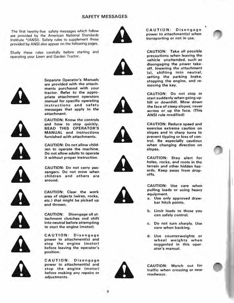
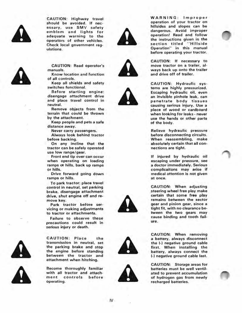

DANGER Batteries produce explosive charges Keep sparks flame and cigarettes away Ventilate when chargshying or using in enclosed space Always shield eyes when working near batteries
CAUTION When working around storage batteries reshymember that all of the exshyposed metal parts are live Never lay a metal object across the terminals as a spark or short circuit may result Sparks lighted matches and exposed flames must be kept away from the battery due to the presence of explosive gas in the battery The liquid in the batteries is acid Use care not to spill it on hands or clothing
POISON Batteries contain sulfuric acid which can cause severe burns Avoid contact with skin eyes or clothing Antidote EXTERNAL flush with water INTERNAL drink large quantities of water or milk Follow with milk of magnesia beaten egg or veg shyetable oil Call physician imshymediately EYES flush with water for 15 minutes and get prompt medical attention Keep out of reach of children
Remember a careful operator is always the best insurance against an accident Give complete and undivided atshytention to the job at hand
CAUTION Set parking brake shut off engine remove key and wait until all engine and attachment motion has stopped before dismounting from the operators seat
WARNING To jump start this machine connect posshyitive jumper cable to battery terminal on starter solenoid and connect negative jumper cable to good engine ground Start engine only when seated in operators seat Stop enshygine before leaving machine Disconnect jumper cables Any other method could result in uncontrolled machine movement
CAUTION Never wear rings or metal watch bands when working with the tractor electrical system or battery as you may ground a live circuit
CAUTION Too much air pressure in the tires can cause tire or rim failure Never put more air pressure in a tire than specified in the operators manual or on the sidewall of the tire If the tire or rim explode because of too much pressure injury can result
CAUTION Before attemptshying to service the attachment Drive Clutch be sure to remove tractor key and spark plug wire(s)
CAUTION Only operate controls from the operators seat to prevent injury
IMPORTANT Always install new decals whenever the old decals are destroyed lost painted over or illegible When individual parts are replaced that have decals attached be sure to install a new decal with the new part Replacement decals are available from your dealer
CAUTION Do not operate machine while under the influence of alcohol or drugs
v
HILLSIDE (SLOPE) OPERATION
Read Understand ObeyWARNING Improper operashytion of your tractor on hill shy
A sides and slopes can be danshygerous Avoid improper opershyation Read and follow the inshystructions given in the section titled Hillside Operation in this manual before operating you r tractor
Avoid operating tractor on hillsides and slopes To minimize the possibility of accidents while operating on hills andor rough terrain obey a combination of rules practices and good common sense
These include
1 Reading understanding and obeying all written safety messages appearing on decals on the mashychine and in operators manuals
2 Learning from your operators manual and carefulshyly from EXPERIENCE how to operate your tractor correctly Know your tractors limitations
3 Knowing the terrain on which you are operating your tractor There are terrain conditions on which your tractor cannot be operated
4 Learning to expect changes in operating condishytions Adding or removing attachments or weight to your tractor will make your tractor perform difshyferently Rain snow loose gravel wet grass etc change the tractive conditions of the terrain reshyquiring changes in your operating technique or not to operate on that terrain
The following paragraphs will cover these practices one at a time Read and study them The examples provided are not all inclusive but will give you a firm understanding of the requirements for avoiding accishydents while operating your tractor
Ingersoll Lawn and Garden Tractors are designed and built to comply with the Voluntary Standard ANSI
(American National Standards Institute)
THE OPERATOR IS THE SOLE JUDGE AS TO THE DEGREE OF SLOPE ON WHICH THIS TRACTOR CAN BE SAFELY OPERATED IF IN DOUBT THAT THIS TRACTOR CAN BE SAFELY OPERATED ON A PARTICULAR SLOPE DO NOT OPERATE ON THAT SLOPE COMMON SENSE MUST PREVAIL
VI
Safety messages are found on the tractor and in the operators manuals These must be understood by the tractor operator to be of value Be sure that these messhysages are studied before starting andor operating the tractor by an operator not familiar with this particular tractor
learn to Operate
Learn your tractors controls from decals on the tracshytor and from instructions in the operators manual Practice how to properly manipulate these controls Practice must be done in a flat area clear of obstacles and bystanders Learn your tractors operating characshyteristics and limitations These include
a amount of engine power available
b engine governor response
c tractive ability
d steering characteristics
e braking characteristics
f movement of travel lever
g forward and reverse ground speeds
h speed of attachment lift
i and others
Attempting any operation which approaches or exshyceeds the tractors limitation is risking an accident
Know the Terrain
Know the terrain on which you are working Find hidshyden obstacles by walking through and inspecting the area prior to operating your tractor on it Mark obshystacles such as rocks ruts or holes with a 6 ft long pole and red flag and stay well clear of these obstacles when operating
Operate your tractor at a ground speed slow enough to insure complete control at all times
Place the transmission in low gear and regulate the throttle control lever slowly and smoothly to maintain this safe speed Do not stop on a hill or slope to change gears
-Always drive in a forward direction when proceeding downhill Never drive up a hill If necessary back up a hill to the desired position Always back up loading ramps and tilt bed trailers If necessary to turn while on a hill always turn downward
Your judgement based on operating experience is the final word in deciding if you should negotiate any given hill or slope If you are in doubt about safety ST A Y OFF THE SLOPE
Under no circumstances should an inexperienced opshyerator attempt to use your tractor on slopes or hillshysides
You may encounter some terrain on which your tracshytor cannot be operated even if a different piece of equipment has operated there in the past
Learn to Compensate for Changes in Operating Conditions
Adding or removing attachments or ballast (such as wheel weights or fluid) change the weight and weight distribution of your tractor and therefore changes your tractors operating characteristics
Be alert to these changes Practice operating the tracshytor after each change has been made
Adding an attachment (weight) to the rear of the tracshytor reduces the weight on the front axle Adding an atshytachment (weight) to the front of the tractor reduces weight on the rear of the tractor You must add counshyterweight to the front if a rear mounted attachment is installed You must add counterweight to the rear if a front mounted attachment is installed
Tractive conditions will vary with weather and terrain and equipment
Areas wet with dew or rain will be more slippery than when dry Areas covered with loose gravel are more slippery than firm dry ground Greater stopping disshytances are required in these slippery areas
Spinning rear wheels tend to move the tractor sideshyways The addition of tire chains will provide more traction to the rear wheels in the forward-reverse dishyrection but less stability in the sideways direction Chains will cause more abrupt starting and stopping
The final word in safe tractor operation rests on your judgement
If in doubt of your safety STAY OFF THE SLOPE
VII
FIGURE 1
1
TO THE OWNER
The Maintenance you give your new tractor is imporshytant Use this manual as your guide Follow these instructions and tips to make sure your tractor opershyates efficiently for many years
We are a factory authorized dealer We have replaceshyment parts which are the same as the original equipshyment
If you need additional aid or information contact us
CY()tMt ~ 9eak
NOTE Ingersoll Equipment Co Inc reserves the right to make improvements in design or changes in specifications at any time without incurring any obligation to install them on units previously sold
IMPORTANT This manual covers many different NOTE model tractors The illustrations usshy
ed in this manual may not be of your tractor
NOTICE
A spark arrester or spark arrester muffler must be used on some machines Check the laws in your area
Some states have regulations for the use of this mashychine in agriculture forestry and construction These laws control the maintenance of spark arrester equipshyment These laws also control the installation of spark arrester equipment on the exhaust system of naturally aspirated engines (engines without a turbocharger)
RADIO INTERFERENCE REGULATIONS OF CANADA
Tractors taken into Canada after September 1 1976 must have resistor spark plugs
Resistor spark plugs and resistor wires for the spark plug must be used for replacement
Printed in USA 10-96-RP-1000-119
- -------
PRODUCT IDENTIFICATION NUMBER (PIN) OR SERIAL NUMBER
When you need parts or information or when you write to your authorized dealer always give the For reference write the numbers below
1 Tractor Model Number
2 Tractor Product Identification Number (P1 N)
3 Engine Model Number
4 Engine Serial Number
5 Engine Specification Number
ENGINE MODEl SERIAL AND SPECIFICATION NUMBERS
ONAN ENGINE FIGURE 3
TRACTOR MODEl AND PRODUCT IDENTIFICATION NUMBER
FIGURE 2
This manual is for the following compact tractors
MODEl 3012 PIN 14145700 and after 3014 PIN 14146700 and after 3016 PIN 14147800 and after 3018 PIN 14181200 and after 3018PS PIN 14181900 and after 4016 PIN 14170800 and after 4020 PIN 14176500 and after 4020PS PIN 14184000 and after
The words Right Left Front and Rear as used in this manual indicate directions when you are in the operators seat in the normal operating position
- 3 shy
ENGINE MODEL SERIAL AND SPECIFICATION NUMBERS
BRIGGS amp STRATTON ENGINE
FIGURE 4
OPERATING INSTRUCTIONS
NEUTRAL
THROTTLE
1 PARKING rlt
BRAKE ~ I
LOCK FFIGURE 5
OPERATING CONTROLS AND INSTRUMENTS
A CAUTION Know the controls The choke must be open during normal operation and how to stop quickly or when you start a warm engine READ THIS OPERATORS MANUAL and instructions
3 THROTTLEfurnished with attachments
A ENGINE LOW IDLE Pull the throttle leverBecome thoroughly familiar rearward Put the throttle in the SLOWpositionwith all tractor and attachshywhen starting and when stopping the engine This ment controls before permits a warming and cooling period operating
TO INCREASE ENGINE SPEED Push the throttle
A lever forward until the needed engine speed is
CAUTION Only operate reached controls from the operators seat to prevent injury Decrease the engine speed during operation for
maximum fuel efficiency Do not cause engine lugging Lugging will cause too much heat and
1 IGNITION KEY AND STARTER SWITCH damage to the engine
TO START Turn the key to the right and hold in the START position
CAUTION Do not changeTO RUN Release the key to the RUN position the engine governor settingswhen the engine starts or overspeed the engineA TO STOP Turn the key to the left to the OFF position
2 CHOKE 4 HEADLIGHTS
TO CLOSE THE CHOKE Push the choke lever TO ILLUMINATE Press the switch to illuminate forward Close the choke to start a cold engine the headlights
TO OPEN THE CHOKE Pull the choke lever rearward Open the choke slowly after the engine TO TURN OFF Press the switch to turn off the starts headlights
- 4 shy
5 BATTERY VOLTAGE INDICATOR LIGHT
The battery voltage indicator light will illuminate when the battery voltage is low and will go out when the battery voltage is acceptable
It is normal for the light to illuminate when the tractor is first started after a period of non-use and to glow when the tractor engine is operated at low idle speed
Stop the engine and have the problem corrected if the indicator light does not go out after running the engine at normal operating speed after a few minutes of operation
It is normal for the Battery Voltage Indicator light to remain out if the engine is stopped when the battery is fully charged and the ignition key is turned to the run position
6 HOUR METER
The electric hourmeter records hours of operation whenever the key is in the RUN position
Utilize the hourmeter to meet the required maintenance schedule
7 BRAKE PEDAL
TO ACTUATE THE BRAKE Push the brake pedal fully down
This action will return the travel control to the NEUTRAL position
The tractor will come to a quick stop
NOTE Do not use the above method if possible
Stop the tractor with the travel control lever
The tractor can be stopped smoothly by slowly returning the travel control lever to the NEUTRAL position
Actuate the brake fully if you can not stop the tracshytor with the travel control lever
See the Operating Procedure Section of this manual for a more complete description of stopping travel
8 PARKING BRAKE LOCK
TO ENGAGE Push the brake pedal fully down
Push down on the parking brake lock
TO DISENGAGE Push the brake pedal a small amount and release
A spring will disengage the parking brake lock
9 HYDRAULIC ATTACHMENT LIFT LEVER
TO LIFT Run the engine
Pull the lever rearward
Release the lever when the needed height is reached
TO LOWER Run the engine
Push the lever forward a small amount
Release the lever when the needed height is reached
When you release this lever a spring will autoshymatically return the lever to the NEUTRAL position
THE FLOAT POSITON Push the lever fully forshyward
A detent holds the lever in the FLOAT position The lever must be manually returned to the NEUTRAL position from the FLOAT position
The FLOAT position prevents hydraulic down pressure on the attachment
See the instructions included with each attachment for correct attachment lift lever use
10 ATTACHMENT DRIVE (PTO) SWITCH
TO ENGAGE Pull switch toggle out and push upshyward See Attachment Drive Clutch Break-in proshycedure in maintenance section in this manual before operating your attachment
The center dash panel indicator light will illuminate when the attachment drive switch is on
TO DISENGAGE Push switch down
The center dash panel indicator light will go out when the attachment drive switch is off
NOTE The attachment drive switch must be off before you can start the engine
- 5 shy
--shy - TRAVEl ~ CONTROL
LEVER DUAL RANGE TRANSAXLE
BRAKE
L
~=~PEDA~ ~~
FIGURE 6 EARLY STYLE RANGE SHIFT
~=JltL=_)JkI~~
i I~ HYDRAULIC
DUAL RANGE
f~~ ~~EVER
gt1~JTRANSAXLE
FIGURE 6A CURRENT STYLE RANGE SHIFT
11 DUAL RANGE TRANSAXLE (EARLY STYLE)
TO SELECT LOW RANGE Put the travel control lever in the NEUTRAL position
Stop the tractor
Pull the lever forward a small amount to go over the neutral locating pin
Pull the lever up beyond the neutral locating pin and release
TO SELECT NEUTRAL Put the travel control lever in the NEUTRAL position
Stop the tractor
Pull the lever forward a small amount to go over the neutral locating pin
Align the hole in the lever with the neutral locating pin and release the lever
TO SELECT HIGH RANGE Put the travel control lever in the NEUTRAL position
Stop the tractor
Pull the lever forward a small amount to go over the neutral locating pin
Push the lever down beyond the neutral locating pin and release
If the range shift does not move easily rotate the gears
To rotate the gears
1 move the travel control lever a small amount into the FORWARD position
2 return the travel control lever to the NEUTRAL position
IMPORTANT The range shift lever must be beyond the neutral locating pin while in LOW or HIGH range If the lever is not in the correct position damage to the gears will result
DUAL RANGE TRANSAXLE (CURRENT STYLE)
TO SELECT LOW RANGE Put travel control lever in NEUTRAL position
Stop tractor
Push lever down and to left Release lever up into LOW RANGE notch
TO SELECT NEUTRAL Put travel control lever in NEUTRAL POSITION
Stop tractor
Push lever down and move lever to align with NEUTRAL notch and release
TO SELECT HIGH RANGE Put travel control lever in NEUTRAL position
Stop tractor
Push lever down and to right Release lever up into HIGH RANGE notch
- 6
12 TRAVEL CONTROL LEVER
TO STOP TRAVEL Put the travel control lever in the NEUTRAL position
TO START FORWARD TRAVEL Depress the travel control lever slightly Slowly and in small amounts move the travel control lever forward
Speed and power will increase as the lever is moved toward the full forward position
TO START REVERSE TRAVEL Depress the travel control lever slightly Slowly and in small amounts move the travel control lever rearward
Speed and power will increase as the lever is moved toward the full reverse position
DO NOT USE FULL SPEED IN REVERSE
Depress the travel control lever whenever you change the lever position to have smoother operation and middotcontrol
The travel control lever automatically returns to the NEUTRAL position when the brake is acshytuated You must hold the travel lever in the needshyed position to maintain travel while the brake is actuated
A neutral start switch is actuated by the travel controlleve~ The lever must be in the NEUTRAL position before you can start the engine
The right hand dash panel indicator light will illumshyinate when the travel control lever is in the Neushytral position The indicator light will go out if the travel control lever is moved from the Neutral position into either forward or reverse
NEUTRAL
1If~ iii ~
FIGURE 7
- 7 shy
PRESTARTING CHECK LIST
A
A A
CAUTION Read operators manuals
Know location and function of all controls
Keep all shields and safety switches functional
Before starting engine disshyengage attachment drive and place travel control in neutral
Remove objects from the terrain that could be thrown by the attachment
Keep people and pets a safe distance away
Never carry passengers Always look behind tractor
before backing On any incline that the tracshy
tor can be safely operated use low rangegear
Front end tip over can occur when operating on loading ramps or hills back up ramps or hills
Drive forward going down ramps or hills
To park tractor place travel control in neutral set parking brake disengage attachment drive shut engine off and reshymove key
Park tractor before servicshying or making adjustments to tractor or attachments
Failure to observe these precautions could result in serious injury or death
CAUTION Do not wear loose clothing which may catch in moving parts
CAUTION Disengage power to attachmentls) and stop the engine (motor) before making any repairs or adjustments
1 Use only clean fuel oil container and funnel
2 Apply oil or grease to all the specified points shown in the Lubrication Chart
3 Check the oil level in the engine and add oil as reshyquired
4 Check the engine air cleaner and air intake screen for dirt or obstructions Clean as required
CAUTION Handle gasoline with care - it is highly flamshymable
a Use approved gasoline container
A b Never remove the fuel cap of or add gasoline to a running or hot engine or an engine that has not been allowed to cool for several minutes after running Never fill the tank indoors and always clean up spilled gasoline
c Open doors if the engine is run in the garage - exshyhaust fumes are dangershyous Do not run the enshygine indoors
A CAUTION Do not smoke when working near fuel
5 Fill the fuel tank with clean fuel Clean the area around the fuel cap before you remove the cap The requirements are listed in the Fuel Specificashytions Section of this manual
6 Check the ventilation hole in fuel tank cap and clean as required
7 Check all operating controls and instruments for correct function before using the tractor
BREAK-IN PROCEDURE
Controlled break-in is the ideal fitting of all internal moving metal parts Using the proper oil and applyshying a conscientious maintenance program during this period helps assure satisfactory service from your engine
Maintain the proper cooling and lubrication during break-in Run the engine at half load for the first three
- 8 shy
hours with intermittent periods of full load to control engine break-in
Check the oil level at least every five operating hours Add oil to keep it at the proper level but never overfill as overfilling may cause the oil to foam and enter the breather system resulting in high oil consumption and oil accumulation in air cleaner housing
STARTING PROCEDURE (Operating the Tractor)
CAUTION Only operate conmiddot 6 Pull the choke lever rearward slowly after the trois from the operators seat engine starts running to prevent injury
7 Permit the engine to warm before applying a load
CAUTION Do not wear NOTE The hydraulic system must be warm before loose clothing which may you use the tractor when air temperatures are catch in moving parts less than 32degF (OdegC) Use the following proshy
cedure NOTICE Your new tractor is equipped with a
switch under the seaL a Set the throttle 13 of the way between the
The tractor engine will stop if you get off the seat SLOW and FAST position when the attachment drive clutch is in the ON position or the travel control lever is in FORWARD b Select the NEUTRAL position of the dual or REVERSE position range transaxle
c Move the travel control lever to the full1- Put the travel control lever in the NEUTRAL FORWARD position position
d Run for several minutes before operating the2 Put the attachment drive switch in the Off posishytractor A noise can occur when the hydrauliction system is cold
CAUTION Disengage all atshytachment clutches and shift into neutral before attempting to start the engine (motor) IMPORTANT DO NOT TRY TO START THE TRACshy
TOR BY PUSHING OR TOWING 3 Push the choke lever forward to close the choke SERIOUS DAMAGE WILL RESULT
TO THE DRIVE SYSTEM The choke setting will change according to the air temperature engine temperature and grade of fuel
Separate Operators Manuals are provided with the attachshy4 Push the throttle lever forward approximately 13 ments purchased with yourof the way between the SLOW and FAST tractor Refer to the apprqshypositions priate attachment operators manual for specific operating
CAUTION Do not allow childshy instructions and safety ren to operate the machine messages that apply to the Do not allow adults to operate attachment it without proper instruction
Remember a careful operatorCAUTION Do not carry passhyis always the best insurancesengers Do not mow when againstmiddot an accident Givechildren and others are complete and undivided atshyaround tention to the job at hand
5 Turn the ignition key to the right and hold in the START position Release the key to the RUN position when the engine starts running
NOTE Release the key immediately when the engine starts If you hold the key in the START position after the engine is running damage can occur Release the key after 30 seconds if the engine does not start running Wait 3 minutes before you try again
- 9 shy
STOPPING PROCEDURE (OPERATING THE TRACTOR)
START SWITCH
TRAVEl ~-CONTROL~ shylEVER
BRAKE ~ THROTTLE PEDAL
FIGURE 8
A CAUTION Know the controls 6 Turn the key to the left to the OFF position and how to stltgtp quickly READ THIS OPERATORS MANUAL and instructions furnished with attachments NOTE Muffler after bang can be prevented by
closing the choke at the same time the key switch is turned to the OFF position This action prevents the entry of air into the
1 Slowly move the travel control lever to the muffler as the engine comes to a stop and NEUTRAL position
therefore prevents combustion within the muffler
2 Completely stop the tractor Actuate the brake pedal if necessary 7 Remove the ignition key
3 Engage the parking brake lock
4 Pull the throttle lever rearward to the SLOW CAUTION Take all possible
A position precautions when leaving the
vehicle unattended such as 5 Permit the engine to cool Run the engine at idle for disengaging the power takeshy
several minutes if the work load was severe off lowering the attachment Is1 shifting into neutral setting the parking brake stopping the engine and reshy
CAUTION Set parking brake moving the key
A shut off engine remove key and wait until all engine and attachment motion has stopshy
CAUTION Disengageped before dismounting from
power to attachments) whenthe operators seat transporting or not in use A
- 10 shy
OPERATING PROCEDURE (OPERATING THE TRACTOR)
Operate the tractor for the first time on a flat area clear of obstructions and persons Learn the operating characteristics of your tractor before trying the first job
1 Select the correct gear range for the job
2 LOW range is for all working operations and hillside use Always use LOW range on hillsides or inclines
CAUTION Use care when pulling loads or using heavy equipment a Use only approved drawshy
bar hitch points
b limit loads to those you can safely control
c Do not turn sharply Use care when backing
d Use counterweights or wheel weights when suggested in this opershyators manual
~_RANGE SHIFT
FIGURE 9 EARLY STYLE SHIFT
FIGURE 9A CURRENT STYLE SHIFT
3 HIGH range is for transport only HIGH range must not be used for hillside operation
4 If the range shift does not move easily rotate the gears
To rotate the gears
a Move the travel control lever a small amount into the FORWARD position
b Return the travel control lever to the NEUTRAL positon
IMPORTANT Completely stop the tractor motion before changing the range The range shift lever must be beyond the NEUTRAL locating pin when in the LOW or HIGH range Gear damage will occur if the lever is not in the correct position
5 Push the throttle lever forward until you get the needed engine speed
Decrease engine speed during operation for maximum fuel eHiciency Do not cause engine lugging Lugging will cause more than normal heat and damage to the engine
6 TO USE FORWARD TRAVEL
a Depress the travel control lever slightly and move it slowly and in small amounts from the NEUTRAL position toward the full FORWARD position
b When you reach the correct speed release the lever
c Return the travel control lever to the NEUTRAL position to stop
d Actuate the brake pedal if the NEUTRAL position does not stop the tractor
NEUTRAL ~
I JI~ FORWARD jIf ~ -shy
FIGURE 10 Travel Control
7 TO USE REVERSE TRAVEL
a Depress the travel control lever slightly and move it slowly and in small amounts from the NEUTRAL position toward the REVERSE position Do not travel at full speed in reverse
b Always keep your hand on the travel control lever when moving in reverse
- 11 shy
c Return the travel control lever to the 11 The rear wheels can slip or spin and an engine NEUTRAL position to stop overload can occur while you go up a small
slope Turn the front wheels toward the bottom d Actuate the brake pedal if the NEUTRAL of the hill before the loss of all traction or power
position does not stop the tractor Do not permit the tractor to move rearward
Always be careful and look behind when you drive down any slope or hillside in reverse
a A return to forward travel will cause too much Do not travel in reverse down a hill or ramp Use torque at the rear wheels The front wheels reverse travel to move up a hill or ramp Always use can raise off the ground and cause severe forward travel when you come down a hill or ramp injury to the operator
b Turning the front wheels can cause too much thrust to the side The tractor can roll over and
A CAUTION Do not stop or
cause severe injury to the operator start suddenly when going upshyhill or downhill Mow down
Always use reverse travel to move up a hill or the face of steep slopes never slope Always use forward travel to move downacross or uJ the face (This a hill or slope ANSI rule modified)
12 Decrease the travel speed before you turn the tractor
WARNING Improper operation of your tractor on
A a Move the travel control lever nearer to the
hillsides and slopes can be NEUTRAL position dangerous Avoid improper operation Read and follow b Decrease the throttle setting the instructions given in the section titled Hillside c Select LOW range in the dual range trans shyOperation in this manual axle before operating your tractor
A CAUTION Reduce speed and exercise extreme caution on slopes and in sharp turns to
8 The travel control lever controls both speed and prevent tipping or loss of conshypower available to the rear wheels of the tractor trol Be especially cautious
when changing direction on During operation the load on the tractor will slopeschange Adjust the position of the travel control lever as required 13 Engage the attachment drive before you put a
load on the attachment 9 TO ACTUATE BRAKES - Hillside Operation
IMPORTANT To prevent clutch damage do not Hold the travel control lever in the needed position engage the attachment drive clutch then push on the brake pedal with engine throttle in FAST
position When you actuate the brake the travel control
14 Actuate the lawnmower over an area of thinlever will return to the NEUTRAL position unless
grass or an area that has been cut you hold the lever in the needed position
The travel control lever can be moved (but the lever CAUTION When using any must be held) while the brake is actuated attachments never direct disshy
charge of material toward byshyKeep the brakes in good repair and correctly standers nor allow anyone adjusted at all times See the preventive near the vehicle while in opershyA
ationmaintenance section of this manual or see your dealer for brake repair 15 Actuate the tiller while in the transport position
Then lower the tiller into the soil to the needed depth
10 Do not move the travel control lever from REVERSE to FORWARD while the tractor 16 Actuate the snowcaster before you make is moving This can cause the front of the tractor contact with the snow to raise off the ground Stop reverse travel completely before you start forward travel This 17 Read your attachment manual for complete is especially important while on a hill or slope attachment operation information
- 12 shy
TROUBLESHOOTING GUIDE
CAUSES SOLUTIONS
ENGINE WILL NOT START
1 Attachment Drive PTO in ON position 1 Put electric clutch in OFF and hydraulic PTO (if equipped) in NEUTRAL position
2 Travel lever in FORWARD or REVERSE 2 Put travel lever in NEUTRAL position position
3 No fuel in tank 3 Fill tank with fresh clean fuel
4 Vent in fuel tank cap restricted or wrong cap 4 Clean vent use properly vented cap on tank
5 Faulty spark plug(s) 5 Replace spark plug(s)
6 Other causes 6 See your dealer
ENGINE LACKS POWER
1 Choke partially closed 1 Open choke
2 Dirty Air Cleaner 2 Clean or replace air cleaner
3 Use of old stale fuel 3 Use clean fresh fuel replace fuel filter
4 Faulty spark plug(s) 4 Replace spark plugs)
5 Engine overheating 5 Clean air baffles and cooling fins
6 Vent in fuel tank cap restricted or wrong cap 6 Clean vent use properly vented cap on tank
7 Other causes 7 See your dealer
ENGINE WILL NOT RUN
1 Engine stops when you get off seat 1 a Sit in seat during normal operation
b Put electric clutch in OFF and hydraulic PTO (if equipped) in NEUTRAL position
c Put travel lever in NEUTRAL position
2 Engine stops when you put travel lever in 2 a Sit in seat during normal operation FORWARD or REVERSE or your engage electric clutch or hydraulic PTO (if equipped) b Faulty seat switch
c Faulty seat switch connector or connector is loose
3 Also see ENGINE LACKS POWER in this 3 Check causes guide
4 Other causes 4 See your dealer
- 13 shy
PREVENTIVE MAINTENANCE
FIGURE 11
As the oWner of an Ingerso tractor you have a machine that is made to high quality standards
Preventive maintenance is important to you
Preventive maintenance is the most efficient way to keep your tractor in top operating condition
The first part of this manual covers instructions needed for daily operation The following instructions will help you in maintenance and adjustment of your tractor
Also see your engine manual for maintenance and adjustment of your engine
- 14 shy
TRACTOR MAINTENANCE CHART (ALSO SEE ENGINE MANUAL FOR ENGINE MAINTENANCE)
AINTENANCE PROCEDURE PAGE FREQUENCY DAILY 25 50 100 500 HOURS HOURS HOURS HOURS
Check hydraulic oil level 26 Daily
Check and clean obstructions from oil cooler 27 Daily
Grease front spindles axle pivot pin front wheel bearings steering gear 29 25 Hours
Oil travel lever implement lift lever NA 50 Hours
Oil brake linkage 24 50 Hours
Check battery electrolyte level Add if necessary 21 50 Hours
Check two speed transaxle oil 28 100 Hours
Change two speed transaxle oil 28 500 Hours
Change hydraulic system oil 26 500 Hours
Change hydraulic oil filter - 27 500 Hours
x
X
X
X
X
X
X
X
X
X
CAPACITIES
HYDRAULIC SYSTEM ENGINE CRANKCASE
REFILL - 6 qts (56 I) ONAN 15 qts (14 I) without filter
TOTAL SYSTEM - 65 qts (6 I) 18 qts (17 I) with filter
TRANSAXLE 1 pint (5 I) BRIGGS amp STRATTON
15 qts (14 I) without filter FUEL TANK 3 gallons (114 I) 175 qts (165 I) with filter
- 15 shy
SPECIFICATIONS
ONAN ENGINE
Make Model Cycle Number of Cylinders Horsepower Cylinder Bore Piston Stroke Displacement Maximum No Load Speed Low Idle Speed Compression Ratio Intake Valve Clearance (Cold) Exhaust Valve Clearance (Cold) Spark Plug Thread Spark Plug Type Ignition Timing Cooling
BRIGGS amp STRATTON ENGINE
Make Model Cycle Number of Cylinders Horsepower Cylinder Bore Piston Stroke Displacement Maximum No Load Speed Low Idle Speed Intake Valve Clearance (cold) Exhaust Valve Clearance (cold) Spark Plug Gap Spark Plug Thread Spark Plug Type Armature Air Gap Cooling
3018PS 4020 4020PS Onan Onan P218 P220
4 Cycle 4 Cycle 2 2
18 (134 kw) 20 (149 kw) 3-14 (825 mm) 3-14 (825 mm) 2-78 (73 mm) 2-78 (73 mm)
477 in l (780 cml ) 47 7 in l (780 cm3) 3600 RPM 3600 RPM 1200 RPM 1200 RPM
7 1 7 1 005 ( 13 mm) 005 (13 mm) 013 (33 mm) 013 (33 mm)
14 mm 14 mm Champion RS 14YC or equivalent 20 0 BTDC 20 0 BTDC
Air Cooled with baffles that direct air around fins on the cylinder and cylinder head
3012 3014 30164016 3018 Briggs amp Stratton Briggs amp Stratton Briggs amp Stratton
294447 303777 350447 4 Cycle 4 Cycle 4 Cycle
2 2 2 14(10 44 kw) 16(119kw) 18 (134kw)
2677 (680mm) 2677 (680mm) 2834 (71 98mm) 260 (66mm) 260 (66mm) 275 (77mm)
293 in 3 (480cc) 293 in3 (480cc) 3475 in 3 (570cc) 3600 RPM 3600 RPM 3600 RPM 1200 RPM 1200 RPM 1200 RPM
004 - 006 (10 - 15 mm)
004 - 006 (10 - 15 mm) 030 (76mm) 030 (76mm) 030 (76 mm)
14 mm 14 mm 14 mm --Champion RC 12 YC 008 - 012 (20 - 30 mm)
Air cooled with baffles that direct air around fins on the cylinder and cylinder head
ELECTRICAL SYSTEM Battery 300 CCA 12 Volt Negative Ground Starter 12 Volt Gear Drive Headlights 12 Volt 32 Candle Power Fuse 30 AMP Flywheel Alternator 12 Volt 20 AMP with
Rectifier Regulator
HYDRAULIC SYSTEM Reservoir Atmospheric with vented fill cap Pump Gear type positive displacment
PS Models 95 GPM 3000 RPM All Others 8 GPM 3000 RPM
Valve Two spool Open center with relief and anti -cavitation spool
Travel Circuit Relief Valve 2100 PSI 14480 kPa) Lift Circuit Relief Valve 575 PSI (3 970 kPa)
-
TRANSAXLE Type Hydraulically driven two gear ranges Differential Standard Bevel Gear
SPEED RANGE MODEL FORWARD AND REVERSE
3000 Low Range 40 MPH (64 kmH) Series High Range 72 - 94 MPH (12 - 15 kmH)
4000 Low Range 3 7 MPH (6 kmH) Series High Range 6 8 - 87 MPH (11 - 14 kmH)
16 shy
CAUTION Too much air TIRES pressure in the tires can cause TYPE SIZE PLY PRESSURE tire or rim failure Never put Front 650 - 8 2 8 PSI (55 kPa) more air pressure in a tire than Rear 8 00-16 2 8 PSI (55 kPa) specified in the operators Rear 1050-12 2 8 PSI (55 kPa) manual or on the sidewall of the tire If the tire or rim Inflate to 14 PSI (95 kPa) for certain attachments explode because of too much pressure injury can result Consult your attachment Operators Manual
c D
A Overall length B Wheel Base C Overall Height D Hood Height - Rear E Minimum Ground Clearance
at Gear Case Rear Wheel Tread Front Wheel Tread Overall Width Tractor Weight Turning Radius
Measure to outside edge of rear wheel
OVERALL MEASUREMENTS
f-----__
I
- +shy
~~ B-A~~ FIGURE 12
3012 3014 3016 3018
65 (1650 mm) 46 (1170 mm) 40 (1020 mm) 355 (900 mm)
72 (180 mm) 2775 (700 mm) 2875 (730 mm) 41 (1050 mm)
683 Ibs (309 kg) 45 (1140 mm)
3018PS 65 (1650 mm) 46(1170mm)
40 (1020 mm) 355 (900 mm)
72 (180 mm) 2775 (700 mm) 2875 (730 mm) 41 (1050 mm)
725 Ibs (329 kg) 53 (1350 mm)
- 17 shy
4016 4020 72 (1830 mm) 48 (1220 mm)
435 (1110 mm) 385 (980 mm)
11 (280 mm) 315 (800 mm) 335 (850 mm) 41 (1050 mm) 765 Ibs (347 kg) 37 (940 mm)
4020PS 72 (1830 mm) 48 (1220 mm)
435 (1110 mm) 385 (980 mm)
11 (280 mm) 315 (800 mm) 33 5 (850 mm) 41 (1050 mm)
805 Ibs (365 kg) 47 (1190 mm)
WIRING DIAGRAM COLOR CODE
(VANGUARD ENGINE) 3 1 White 8 Lite Green NEUTRAL 2 Purple 9 Yellow3012 3016 - ALL LIGHT 3 Red 10 Blue3014 4016 Without Rear 3
4 Dark Green 11 Red wwhite3 IChassis PTO Wire Harness PTO 5 Black 12 Yellow wblack3 LIGHT 6 Brown 13 GreyCHARGE 7 Orange 14 TanregLIGHT
11 ~reg HOURMETER
TO CARBURETOR SOLENOID
3
4
~4~ 4
8
5
yen ~ ~ c ~
NEUTRAL LIGHT SWITCH
STARTER
~
SEAT ~14 SWITCH
LIGHT 13 ~ ~ ~ 8 PTOSWITCH
CLUTCH
HEADLIGHTS
FIGURE 13
--
- - -
WIRING DIAGRAM (VANGUARD ENGINE) 3018 - All
30144016 With Rear Chassis PTO Wire Harness
~9 a0laquoZ t-- shy ~~ u~STARTER 00 ~ t- (f) 2
LIGHT bull
NEUTRAL SW~Ttl ~r1
START ~ ~ r 4 I 5
2
I I3
----____ _
-- - -1
I I
2
~--
L_~
L---
2
Tr1 ~ ~5
LIGHT
r
10
OFF SEAT HEADLIGHTS OPERATION
SWITCH
ELECTRICAL PTO ~ bull
1 1 HYDRAULlC~ TAILTO MAGNETO ~ r PTO LIGHTSGROUND a a SWITCHES Jo tshy yw 00 ~~
SWITCH 1 ~ 6
(~ 15 11
13 r SOLENOID INEUTRAL 4 LIGHT cqjJ====~l1W I 5
PTO I LIGHT C-1J----gt-_~ 5 3 Icu _J
BATTERY shyLIGHT
I I
I I
WIRE I
HARNESS r L _
12
BATTERY 5
SWITCH
F~ 5 ~j ~101 5 BG L-14
S7 I A 4 PTO - 3
VOLTAGE 6 SWITCH
SENSOR 12 IGNITION 5 ~5SWITCH II t==j ~1~------------------------- shyI--~_ ~ -
~~ 11 FIGURE 14
88
0000
~ 8 shy 1
7
I
I
16 -
I I
I
r I I I
HOUR METER
COLOR CODE
1 Black 2 Black wwhite 3 Brown wwhite 4 Red w Iwhite 5 Red 6 Gray wblack 7 Gray 8 Black wyellow 9 Black wired
10 Tan 11 Tan wblack 12 Brown 13 Yellow 14 Blue 15 Yellow wblack 16 Blue wwhite 1 7 Lite Green
- 19 shy
COUPLER ~ j WIRING DIAGRAM (ONAN ENGINE) SWITCH i (3018PS 4020 4020PS)I
~ COLOR CODE COUPLER 9 j 9 TAILLIGHTS 1
PTO SWITCHES IIf Used)
1 r _
WIRE ~
I HARNESS L _
WIREHARNESS
2 3 4 5 6 7 8 9
10 11 12 13 14 15 16
ELECTRIC PTO
I
CONDEN~~_
SWITCH 1 HARNESS (If Used) I ~ 1 SEAT
~ rlMS~ITCH
I ir ~
99
I 11 - - shy_ __ __ J
1 L ~ raquo)
HEADLIGHTS
TRAVEL SWITCHES
6 COIL
I~ 10
9
r - - - shy
lUlL
I 8 sect ~
9
8
2
5
0+
L_
II 15 IJ1 fJ 11 uuml ummn ~--1 I
PTOSWITCH
~NITION SWITCH
8 ___ I
II I I ~ I III 8~ HOURMETER
BATTERY
~ ~5 1 13 ~ q UOAn rgtUT9
FUSE
8
9
FIGURE 15
STARTER
I r AND
SOLENOID
Tan Dark Blue Red wwhite Yellow Red Pink Grey Dark Green Black White Grey wwhite Brown Orange Lite Green Blue Blue wwhite
STORAGE BATTERY
DANGER Batteries produce explosive charges Keep sparks flame and cigarettes away Ventilate when chargshying or using in enclosed space Always shield eyes when working near batteries
CAUTION Never wear rings or metal watch bands when working with the tractor elecshytrical system or battery as you may ground a live circuit
POISON Batteries contain sulfuric acid which can cause severe burns Avoid contact with skin bull eyes or clothing Antidote EXTERNAL flush with water INTERNAL drink large quantities of water or milk Follow with milk of magnesia beaten egg or veshygetable oil Call physician imshymediately EYES flush with water for 15 minutes and get prompt medical attention Keep out of reach of children
CAUTION When working around storage batteries reshymember that all of the exshyposed metal parts are live Never lay a metal object across the terminals as a spark or short circuit may reshysult Sparks lighted matches and exposed flames must be kept away from the battery due to the presence of exploshysive gas in the battery The li shyquid in the batteries is acid Use care not to spill it on hands or clothing
BATTERY MAINTENANCE
1 Add distilled water as required to keep the water level above the ceil separators Check at 50 HOUR intervals of operation or every week Normal water consumption is 1 ounce (30 ml) every 25 HOURS of operation More than norshymal water consumption indicates
a a battery with a leak
b a charging system that is charging too much
- 21 shy
2 Make sure the battery is fastened in position The battery cables must not contact the battery surshyface except at the connection
3 Keep the battery in a clean and dry condition
4 Use a hydrometer to check the specific gravity of the battery If your battery will not keep the corshyrect specific gravity replace it For the correct reshyplacement battery see the specification section of this manual
IMPORTANT A battery having a specific gravity reading of 1175 will become frozen at approximately QOF (-18OC)
ADDING WATER
Always use mineral free or distilled water in your batshytery When the temperature is 32degF (OdegC) or less imshymediately charge the battery after adding water This will mix the water and electrolyte If the water is not mixed it will stay on top and become frozen
ELECTROLYTE LEVEL ABOVE P TES
FIGURE 16
Make a weekly check of the electrolyte level
1 Remove the battery caps
2 Visually check each cell
3 Add water before you see the separators
NOTE Do not fill too much Keep the electrolyte level below the base of the filler tubes
BATTERY CAPS
Always keep the battery caps in place and tight Make sure the holes in the caps are open Ventilation must occur to prevent pressure in the cells
CABLE TERMINALS MJD BATTERY POSTS HOW TO USE JUMPER CABLES AND A BOOSTER BATTERY
Keep the battery terminals clean and tight
1 Remove all corrosion with a wire brush Always wear protective goggles and clothing when
2 Wash with a neutral solution you work near batteries Prevent acid from coming in contact with your skin or clothing
3 Apply a thin layer of light grease to prevent corroshysion Connect the jumper cables as shown below Follow
the numbers for the correct sequence of installation
A CAUTION When removing a To remove the jumper cables reverse the sequence battery always disconnect the ( -) negative ground cable first When installing the batshytery always connect the (-)
To prevent any possible sparks near the battery negative ground cable last
1 Make sure the last connection is as far as possible from the battery
IDLE BATTERY 2 Do not let the ends of the cables make contact
When the tractor is not used regularly the storage with each other battery will slowly lose voltage Charge the battery at regular intervals to keep the hydrometer reading at 3 If the booster battery is on another machine make 1250 or more sure machines do not make contact
BATTERY TERMINAL
ON THE SOLENOID
2
4 )
ENGINE BLOCK
A
+ BOOSTER BATTERY
--
I (
FIGURE 17
WARNING To jump start this machine connect positive jumper cable to battery termishynal on starter solenoid and connect negative jumper cashyble to good engine ground Start engine only when seated in operators seat Stop enshygine before leaving machine Disconnect jumper cables Any other method could reshysult in uncontrolled machine movement
- 22 shy
HEADLIGHTS
To replace the headlight bulb RETAINERIIII AND SCREW Remove the two screws and retainers
2 Remove the headlight receptacle
3 Push in and turn counterclockwise to remove the bulb
4 Push in and turn clockwise to install the new bulb
5 Install the receptacle Put one gasket between the lens and grille Put the other gasket in the groove between the lens and the receptade
6 Install the retainers with the mounting screws
NOTE The new bulb will not illuminate until the GASKETreceptacle has a ground connectiomiddotn
FIGURE 18
~ I ~
FUSE
The 30 amp fuse is located next to the hydraulic oil reshyservoir This fuse protects all circuits except the starter
otor
Use the following procedure to replace a fuse
a TO REMOVE Hold the fuse holder while you pull up on the fuse
b Inspect and clean the contacts of the fuse holder (if required)
c TO INSTALL Push firmly into the fuse holder
FIGURE 19
ATTACHMENT DRIVE CLUTCH BREAK-IN PROCEDURE
To insure normal clutch lining wear life the lining must 3 Engage and disengage clutch 5 times be burnished using the following procedure 10 seconds on 10 seconds off
1 Install the mower or snow blower attac hment 4 Increase engine speed to 34 throttle
I Run engine at 12 throttle 5 Engage and disengage clutch 5 more times 10 seconds on 10 seconds off
- 23 shy
BRAKE
FIGURE 20
LUBRICATION
Apply several drops of oil to each pivot point on the brake linkage Make sure no oil gets on the brake lining or the brake drum
ADJUSTMENT
The brake is correctly adjusted when
a a push of the pedal brings the tractor to a quick stop
b the travel control lever returns automatically to the NEUTRAL position from both FORWARD and REVERSE
Adjust the brakes if needed Use the procedure below
1 Put the tractor on a hard level surface a concrete floor for example
2 Put the dual range lever in the NEUTRAL position
3 Release the brakes
4 Remove the cotter pin clevis pin and clevis from the guide
5 Loosen the lock nut
6 Push the guide rearward Make contact between the dowel pins and arms
7 Tighten the adjusting bolt one half turn at a time Push the tractor with medium force after each adjustment
8 When the tractor can not be pushed with medium force loosen the adjusting bolt one turn Make sure the brake drum moves freely
NOTE Do not permit the adjusting bolt to become too tight This will cause distortion of the brake band
9 Tighten the lock nut
10 Hold the guide rearward
11 Turn the clevis Align the hole in the clevis with the rear of the slot in the guide Install the clpvis clevis pin and a new cotter pin
- 24 shy
FUEL
Always use clean fresh gasoline and a funnel with a ter Use regular no-lead gasoline with minimum
ctane ratings as follows
Research Method 90
Motor Method 82
Average 87
In the United States the average octane rating is shown on gasoline pumps In other countries if the method is not given it is the Research Method Noshylead fuel leaves less combustion chamber deposits Leaded gasoline may be used only if no-lead gasoline is not available
CAUTION Handle gasoline with care - it is highly flamshymable
a Use approved gasoline container
b Never remove the fuel cap of or add gasoline to a running or hot engine or an engine that has not been allowed to cool for several minutes after running Never fill the tank indoors and always clean up spilled gasoline
c Open doors if the engine is run in the garage - exshyhaust fumes are dangershyous Do not run the enshy
CAUTION Never store the equipment with gasoline in
the tank inside a building where fumes may reach an open flame or spark Allow the engine to cool before storing in any enclosure
CAUTION Do not smoke when working near fuel
Purchase gasoline in small quantities Fresh gasoline reduces chance of gum deposits forming and clogging the fuel system and ensures a fuel blended for the seashyson Do not use gasoline left over from the previous season
Do not add oil to the gasoline
If a restriction of fuel occurs replace the filter and clean the vent in the fill cap
IMPORTANT Damage to fuel system components will occur if gasoline containing alcoshyhol is used Use only regular leaded or no lead gasoline which does not contain alcohol Avoid using gas line de-iceradditives
gine indoors
FIGURE 21
- 25 shy
HYDRAULIC OIL
HYDRAULIC OIL FIll CAP
fl r- shy
FIGURE 22
Change the hydraulic oil after each 500 HOURS of use Replace the hydraulic oil seasonally according to the chart below
AIR TEMPERATURE Oil VISCOSITY
Above 32degF (OdegC) SAE 2OW40
Below 32degF (O degC) SAE 5W20
Use API Service Classification SE or CC
Ingersoll Custom Blend motor oil is recommended This oil is a special blend for hydraulic applications
The oil level must be kept 5 to 6 (120 mm to 150 mm) down from the top of the filler neck
Use the following procedure to drain the hydraulic system
1 Remove the spark plug(s) from the engine
2 Ground the spark plug wire(s) to the engine block
3 Place an oil drain pan with a capacity of two gallons under the travel control valve
4 Remove the 14 hex socket plug
5 Crank the engine to pump the oil out the drain hole
6 Install the drain plug spark plug(s) and wire(s)
7 Fill the reservoir to 5 to 6 (120 mm to 150 mm) from the top of the filler neck
8 Run the engine and (a) drive forward and reverse a short distance and (b) raise and lower the hydraulic lift two times Check the oil level again
IMPORTANT Make sure oil reservoir is filled to the proper level Overfilling will cause oil leakage Underfilling will cause cavitation and intermittant drive
------~~ ~
HYDRAULIC Oil DRAIN PLUG ~i i-- shy
FIGURE 23
- 26 shy
HYDRAULIC OIL COOLER
The hydraulic oil cooler must be kept clean and nobstructed at all times
Check the hydraulic oil cooler DAILY before operating your tractor and frequently during use
If debris builds up on the screen during tractor operation STOP the tractor engine immediately and clean the debris off
An obstructed hydraulic oil cooler can cause the tractor hydraulic system and engine to overheat and fail prematurely
HYDRAULICFIGURE 24 OIL COOLER
HYDRAULIC OIL FILTER
The hydraulic oil system is protected by an oil filter
The hydraulic oil filter is located behind RH air screen on tower
Replace oil filter after every 500 hours of use when you change hydraulic oil Replace more often if oil becomes contaminated
To replace hydraulic oil filter
1 Remove RH air screen on tower
2 Use suitable size filter wrench to loosen filter
3 Apply clean oil to gasket of new filter
4 Install filter manually until tight
5 Tighten filter one full turn with wrench RH AIR
6 Check filter for leaks after you fill the hydraulic SCREEN system (See Hydraulic Oil Section)
7 Install RH air screen
FIGURE 25
- 27 shy
SEAT
ADJUSTMENT
If your seat is not equiped with an adjustment lever follow this procedure
1 Loosen the four bolts that hold the seat to the seat hinge
2 Move the seat either forward or rearward to get the correct position on the seat hinge
3 Tighten the bolts
MAINTENANCE
1 Clean the seat regularly Use a special vinyl cleaner Do not use a solvent as this will damage the seat
FIGURE 26 2 Severe heat or cold can damage the seat Protection from these conditions is important Put a cover on the seat for protection against weather conditions and water It is best to put the tractor in a building when not in use
3 During operation in severe weather conditions you can easily damage the seat Be careful not to damage the seat when you get on and off the tracshytor
4 If the seat gets a small tear apply a vinyl repair tape over the damaged area Black vinyl repair tape can be purchased locally
TRANSAXlE
Change the oil in the transmission after each 500 AIR TEMPERATURE OIL TYPE amp VISCOSITY HOURS of operation
All Temperatures API Service Class SE or CC The oil drain plug is located on the right hand side of the transaxle housing SAE20W40or
SAE 80 EP Gear Lube The oil level check plug is located on the right hand side of the transaxle housing just above the drain plug Capacity One Pint 15 I)
The oil fill plug is located on the rear of the transaxle housing ~
CHECK PLUG
LJshyOil Fill OJ
middota---l~middot
FIGURE 27 FIGURE 28
- 28 shy
CHASSIS LUBRICATION
Apply grease after every 25 HOURS of operation to he
a front wheel spindles
NOTE Lift front of tractor to permit grease to flow from top and bottom of spindle
b front wheel bearings
NOTE Remove dust caps from front wheel hubs before greasing front wheel bearings The trapped air behind the dust caps can prevent the full lubrication of the bearings
c axle pivot pin
d steering gear - apply a small amount of grease to the gear teeth
e lift shaft
Use number 1 multi-purpose grease (Lithium Base) for all lubrication fittings Use as many strokes as required until you see grease pushing out of assembly
Always wipe dirt from fitting before applying the rease gun
GREASE~~~--~~
FIGURE 29
Front Wheel Spindle Bearings and Axle Pivot Pin
FIGURE 30
Steering Gear and Lift Shaft
- 29 shy
______
STEERING ADJUSTMENT
CAUTION When adjusting
A steering wheel free play make certain that some free play remains between the sector gear and pinion gear since a tight fit with no clearance beshytween the two gears may cause binding and tooth fail shyure
IMPORTANT Check for loose or worn ball joints drag link or tie rod before adjusting the steering gear Tighten or replace these components as required
The tractor is assembled with shim washers between the steering gear and the support bracket See the illustration When the gear teeth wear more free movement occurs If too much free movement occurs adjust the steering gear
1 Disconnect the drag link from the steering gear
2 Remove the nut securing the steering gear
3 Remove the steering gear
4 Remove one or more shim washers from above the steering gear
5 Put the steering gear in place on the pivot shaft
TOE-IN ADJUSTMENT
1 Put the tractor on a hard and level surface like a concrete floor
2 Make sure the front tires have equal air pressure
3 Find the centerline of the front tires See the figure below
1 MEASUREMENT A
4 FRONT -
1 E lUI lU ~
V -shy-- MEASUREMENT B
FIGURE 31
)
- 30 shy
ft MOUNTING BOLT
U ~ PLAIN WASHER-~____ ~ SUPPORT
PIVOT
SHAF~ ~o 3 ___ sect-PLAIN WASHERS
W~~~RS~ 0
0STEERING ~) GEAR ----~
SHIM WASHER- b
~STEERING SHAFT
PLAIN WASHER
e-----shyltQ)
LOCKWASHER IS --NUT
FIGURE 32
6 Put the shim washers washers and the nut on the steering gear bolt and tighten securely The total number of the shim washers must always be the same
4 If you can not find the centerline
a raise the front wheels off the ground
b spin each wheel and put a mark at the centerline with chalk
5 Measure the distance between each centerline or chalk mark
MeasurementA must be 18 to 38 (32 mm to 95 mm) less than measurement S Soth measurements front and rear must be taken at spindle height above the floor
6 Loosen both lock nuts on the tie rod
NOTE Do not remove the ball joints from the king pins Turn the tie rod to change the toe-in
7 Turn the ball joints off of the tie rod to decrease the toe-in
8 Turn the ball joints onto the tie rod to increase the toe-in
MANUAL ORDERING PROCEDURE
These manual are available from the Ingersoll Equipshylent Co Inc
a Parts Manual (includes part numbers and exploded views of your equipment assemblies)
b Operators Manual (includes specificashytions operating procedures and maintenance procedures for your equipment)
c Service Manual (includes cedures for your tractor)
repair proshy
To make sure you receive the correct manuals always have the following numbers available
Tractor Model No
Tractor Serial No _____________
Attachment Model No
Attachment Serial No
Each attachment usually has a separate parts manual and Operators Manual They are not included with the tractor
To place an order
1 Call your local dealer or
2 Contact Ingersoll Equipment Co Inc PO Box 5001 Winneconne WI 54986 Phone 414-582-5000 Attention Manual Order
All orders will include charges for postage handling and CO D if applicable
Prices are subject to change without notice Contact us for current prices
Please allow 2-3 weeks for delivery
- 31
Printed in USA
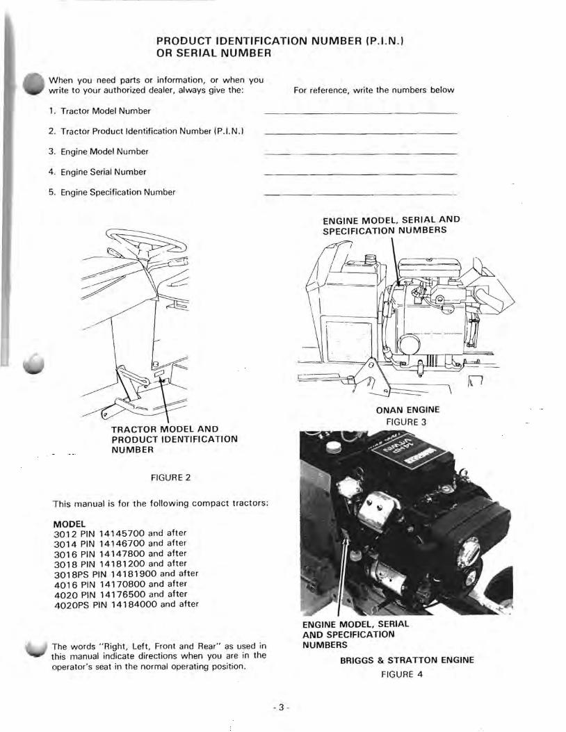
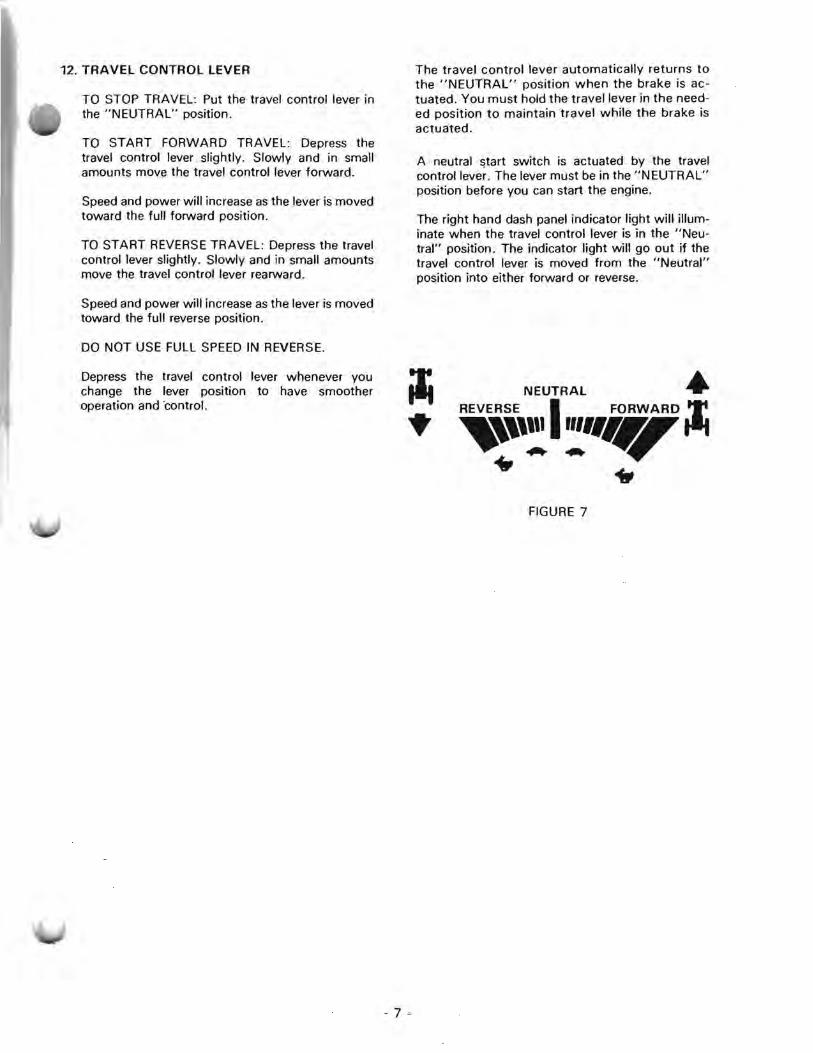
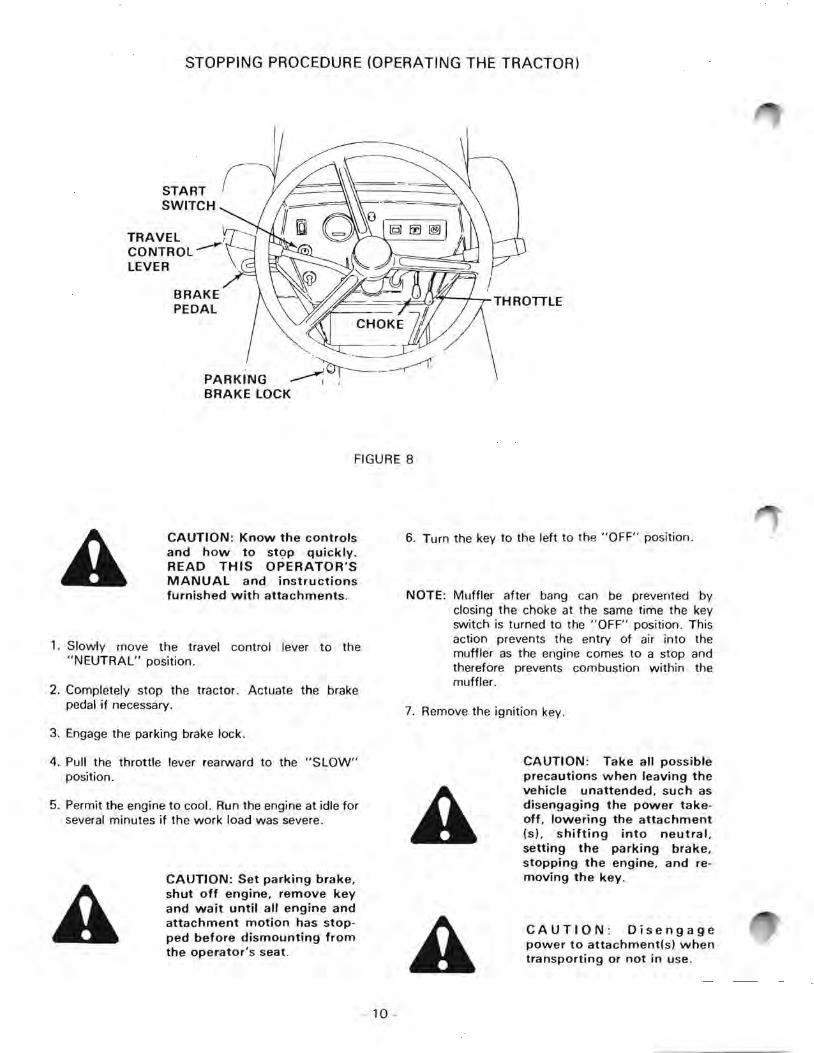
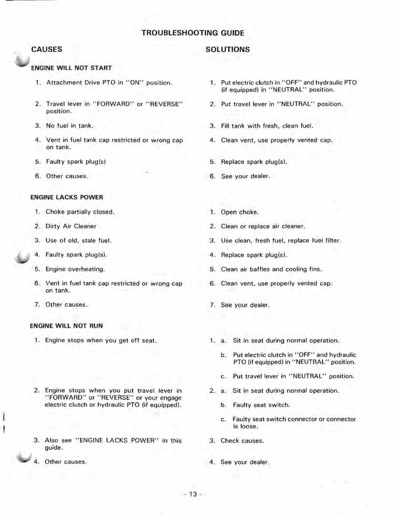
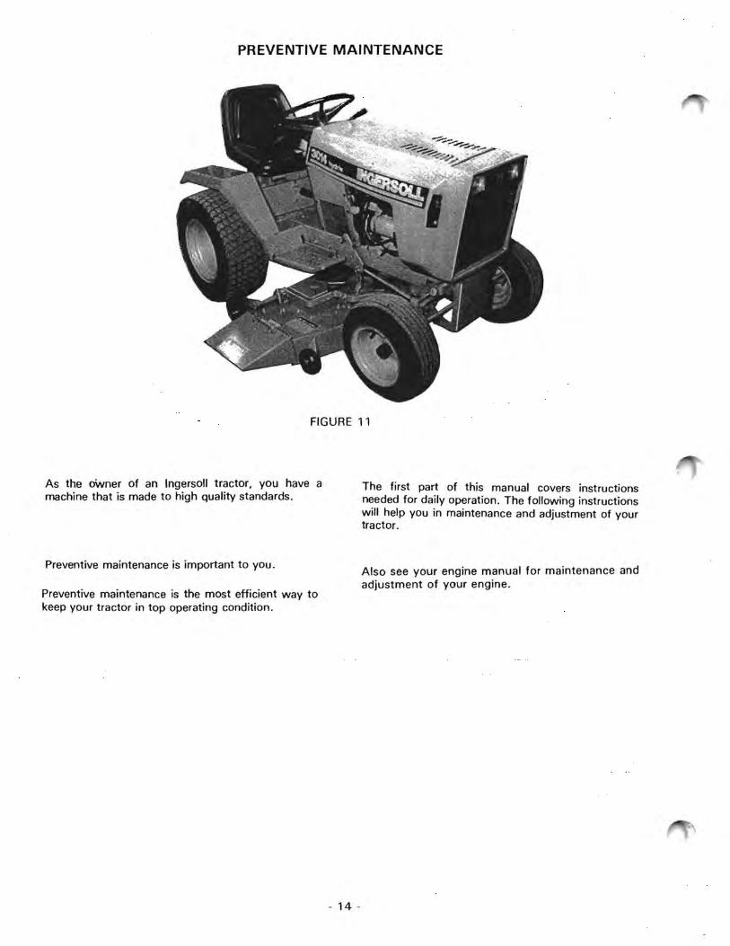
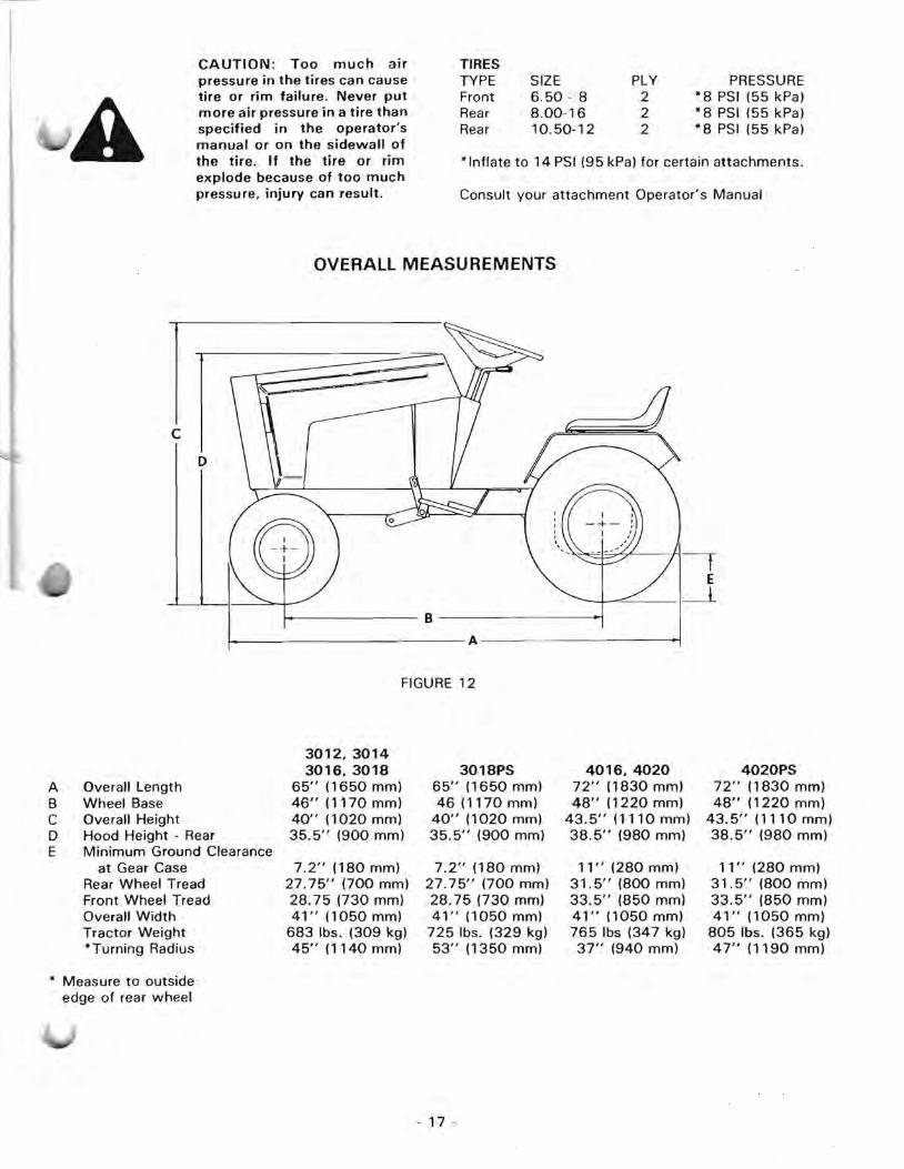

--
- - -
WIRING DIAGRAM (VANGUARD ENGINE) 3018 - All
30144016 With Rear Chassis PTO Wire Harness
~9 a0laquoZ t-- shy ~~ u~STARTER 00 ~ t- (f) 2
LIGHT bull
NEUTRAL SW~Ttl ~r1
START ~ ~ r 4 I 5
2
I I3
----____ _
-- - -1
I I
2
~--
L_~
L---
2
Tr1 ~ ~5
LIGHT
r
10
OFF SEAT HEADLIGHTS OPERATION
SWITCH
ELECTRICAL PTO ~ bull
1 1 HYDRAULlC~ TAILTO MAGNETO ~ r PTO LIGHTSGROUND a a SWITCHES Jo tshy yw 00 ~~
SWITCH 1 ~ 6
(~ 15 11
13 r SOLENOID INEUTRAL 4 LIGHT cqjJ====~l1W I 5
PTO I LIGHT C-1J----gt-_~ 5 3 Icu _J
BATTERY shyLIGHT
I I
I I
WIRE I
HARNESS r L _
12
BATTERY 5
SWITCH
F~ 5 ~j ~101 5 BG L-14
S7 I A 4 PTO - 3
VOLTAGE 6 SWITCH
SENSOR 12 IGNITION 5 ~5SWITCH II t==j ~1~------------------------- shyI--~_ ~ -
~~ 11 FIGURE 14
88
0000
~ 8 shy 1
7
I
I
16 -
I I
I
r I I I
HOUR METER
COLOR CODE
1 Black 2 Black wwhite 3 Brown wwhite 4 Red w Iwhite 5 Red 6 Gray wblack 7 Gray 8 Black wyellow 9 Black wired
10 Tan 11 Tan wblack 12 Brown 13 Yellow 14 Blue 15 Yellow wblack 16 Blue wwhite 1 7 Lite Green
- 19 shy
COUPLER ~ j WIRING DIAGRAM (ONAN ENGINE) SWITCH i (3018PS 4020 4020PS)I
~ COLOR CODE COUPLER 9 j 9 TAILLIGHTS 1
PTO SWITCHES IIf Used)
1 r _
WIRE ~
I HARNESS L _
WIREHARNESS
2 3 4 5 6 7 8 9
10 11 12 13 14 15 16
ELECTRIC PTO
I
CONDEN~~_
SWITCH 1 HARNESS (If Used) I ~ 1 SEAT
~ rlMS~ITCH
I ir ~
99
I 11 - - shy_ __ __ J
1 L ~ raquo)
HEADLIGHTS
TRAVEL SWITCHES
6 COIL
I~ 10
9
r - - - shy
lUlL
I 8 sect ~
9
8
2
5
0+
L_
II 15 IJ1 fJ 11 uuml ummn ~--1 I
PTOSWITCH
~NITION SWITCH
8 ___ I
II I I ~ I III 8~ HOURMETER
BATTERY
~ ~5 1 13 ~ q UOAn rgtUT9
FUSE
8
9
FIGURE 15
STARTER
I r AND
SOLENOID
Tan Dark Blue Red wwhite Yellow Red Pink Grey Dark Green Black White Grey wwhite Brown Orange Lite Green Blue Blue wwhite
STORAGE BATTERY
DANGER Batteries produce explosive charges Keep sparks flame and cigarettes away Ventilate when chargshying or using in enclosed space Always shield eyes when working near batteries
CAUTION Never wear rings or metal watch bands when working with the tractor elecshytrical system or battery as you may ground a live circuit
POISON Batteries contain sulfuric acid which can cause severe burns Avoid contact with skin bull eyes or clothing Antidote EXTERNAL flush with water INTERNAL drink large quantities of water or milk Follow with milk of magnesia beaten egg or veshygetable oil Call physician imshymediately EYES flush with water for 15 minutes and get prompt medical attention Keep out of reach of children
CAUTION When working around storage batteries reshymember that all of the exshyposed metal parts are live Never lay a metal object across the terminals as a spark or short circuit may reshysult Sparks lighted matches and exposed flames must be kept away from the battery due to the presence of exploshysive gas in the battery The li shyquid in the batteries is acid Use care not to spill it on hands or clothing
BATTERY MAINTENANCE
1 Add distilled water as required to keep the water level above the ceil separators Check at 50 HOUR intervals of operation or every week Normal water consumption is 1 ounce (30 ml) every 25 HOURS of operation More than norshymal water consumption indicates
a a battery with a leak
b a charging system that is charging too much
- 21 shy
2 Make sure the battery is fastened in position The battery cables must not contact the battery surshyface except at the connection
3 Keep the battery in a clean and dry condition
4 Use a hydrometer to check the specific gravity of the battery If your battery will not keep the corshyrect specific gravity replace it For the correct reshyplacement battery see the specification section of this manual
IMPORTANT A battery having a specific gravity reading of 1175 will become frozen at approximately QOF (-18OC)
ADDING WATER
Always use mineral free or distilled water in your batshytery When the temperature is 32degF (OdegC) or less imshymediately charge the battery after adding water This will mix the water and electrolyte If the water is not mixed it will stay on top and become frozen
ELECTROLYTE LEVEL ABOVE P TES
FIGURE 16
Make a weekly check of the electrolyte level
1 Remove the battery caps
2 Visually check each cell
3 Add water before you see the separators
NOTE Do not fill too much Keep the electrolyte level below the base of the filler tubes
BATTERY CAPS
Always keep the battery caps in place and tight Make sure the holes in the caps are open Ventilation must occur to prevent pressure in the cells
CABLE TERMINALS MJD BATTERY POSTS HOW TO USE JUMPER CABLES AND A BOOSTER BATTERY
Keep the battery terminals clean and tight
1 Remove all corrosion with a wire brush Always wear protective goggles and clothing when
2 Wash with a neutral solution you work near batteries Prevent acid from coming in contact with your skin or clothing
3 Apply a thin layer of light grease to prevent corroshysion Connect the jumper cables as shown below Follow
the numbers for the correct sequence of installation
A CAUTION When removing a To remove the jumper cables reverse the sequence battery always disconnect the ( -) negative ground cable first When installing the batshytery always connect the (-)
To prevent any possible sparks near the battery negative ground cable last
1 Make sure the last connection is as far as possible from the battery
IDLE BATTERY 2 Do not let the ends of the cables make contact
When the tractor is not used regularly the storage with each other battery will slowly lose voltage Charge the battery at regular intervals to keep the hydrometer reading at 3 If the booster battery is on another machine make 1250 or more sure machines do not make contact
BATTERY TERMINAL
ON THE SOLENOID
2
4 )
ENGINE BLOCK
A
+ BOOSTER BATTERY
--
I (
FIGURE 17
WARNING To jump start this machine connect positive jumper cable to battery termishynal on starter solenoid and connect negative jumper cashyble to good engine ground Start engine only when seated in operators seat Stop enshygine before leaving machine Disconnect jumper cables Any other method could reshysult in uncontrolled machine movement
- 22 shy
HEADLIGHTS
To replace the headlight bulb RETAINERIIII AND SCREW Remove the two screws and retainers
2 Remove the headlight receptacle
3 Push in and turn counterclockwise to remove the bulb
4 Push in and turn clockwise to install the new bulb
5 Install the receptacle Put one gasket between the lens and grille Put the other gasket in the groove between the lens and the receptade
6 Install the retainers with the mounting screws
NOTE The new bulb will not illuminate until the GASKETreceptacle has a ground connectiomiddotn
FIGURE 18
~ I ~
FUSE
The 30 amp fuse is located next to the hydraulic oil reshyservoir This fuse protects all circuits except the starter
otor
Use the following procedure to replace a fuse
a TO REMOVE Hold the fuse holder while you pull up on the fuse
b Inspect and clean the contacts of the fuse holder (if required)
c TO INSTALL Push firmly into the fuse holder
FIGURE 19
ATTACHMENT DRIVE CLUTCH BREAK-IN PROCEDURE
To insure normal clutch lining wear life the lining must 3 Engage and disengage clutch 5 times be burnished using the following procedure 10 seconds on 10 seconds off
1 Install the mower or snow blower attac hment 4 Increase engine speed to 34 throttle
I Run engine at 12 throttle 5 Engage and disengage clutch 5 more times 10 seconds on 10 seconds off
- 23 shy
BRAKE
FIGURE 20
LUBRICATION
Apply several drops of oil to each pivot point on the brake linkage Make sure no oil gets on the brake lining or the brake drum
ADJUSTMENT
The brake is correctly adjusted when
a a push of the pedal brings the tractor to a quick stop
b the travel control lever returns automatically to the NEUTRAL position from both FORWARD and REVERSE
Adjust the brakes if needed Use the procedure below
1 Put the tractor on a hard level surface a concrete floor for example
2 Put the dual range lever in the NEUTRAL position
3 Release the brakes
4 Remove the cotter pin clevis pin and clevis from the guide
5 Loosen the lock nut
6 Push the guide rearward Make contact between the dowel pins and arms
7 Tighten the adjusting bolt one half turn at a time Push the tractor with medium force after each adjustment
8 When the tractor can not be pushed with medium force loosen the adjusting bolt one turn Make sure the brake drum moves freely
NOTE Do not permit the adjusting bolt to become too tight This will cause distortion of the brake band
9 Tighten the lock nut
10 Hold the guide rearward
11 Turn the clevis Align the hole in the clevis with the rear of the slot in the guide Install the clpvis clevis pin and a new cotter pin
- 24 shy
FUEL
Always use clean fresh gasoline and a funnel with a ter Use regular no-lead gasoline with minimum
ctane ratings as follows
Research Method 90
Motor Method 82
Average 87
In the United States the average octane rating is shown on gasoline pumps In other countries if the method is not given it is the Research Method Noshylead fuel leaves less combustion chamber deposits Leaded gasoline may be used only if no-lead gasoline is not available
CAUTION Handle gasoline with care - it is highly flamshymable
a Use approved gasoline container
b Never remove the fuel cap of or add gasoline to a running or hot engine or an engine that has not been allowed to cool for several minutes after running Never fill the tank indoors and always clean up spilled gasoline
c Open doors if the engine is run in the garage - exshyhaust fumes are dangershyous Do not run the enshy
CAUTION Never store the equipment with gasoline in
the tank inside a building where fumes may reach an open flame or spark Allow the engine to cool before storing in any enclosure
CAUTION Do not smoke when working near fuel
Purchase gasoline in small quantities Fresh gasoline reduces chance of gum deposits forming and clogging the fuel system and ensures a fuel blended for the seashyson Do not use gasoline left over from the previous season
Do not add oil to the gasoline
If a restriction of fuel occurs replace the filter and clean the vent in the fill cap
IMPORTANT Damage to fuel system components will occur if gasoline containing alcoshyhol is used Use only regular leaded or no lead gasoline which does not contain alcohol Avoid using gas line de-iceradditives
gine indoors
FIGURE 21
- 25 shy
HYDRAULIC OIL
HYDRAULIC OIL FIll CAP
fl r- shy
FIGURE 22
Change the hydraulic oil after each 500 HOURS of use Replace the hydraulic oil seasonally according to the chart below
AIR TEMPERATURE Oil VISCOSITY
Above 32degF (OdegC) SAE 2OW40
Below 32degF (O degC) SAE 5W20
Use API Service Classification SE or CC
Ingersoll Custom Blend motor oil is recommended This oil is a special blend for hydraulic applications
The oil level must be kept 5 to 6 (120 mm to 150 mm) down from the top of the filler neck
Use the following procedure to drain the hydraulic system
1 Remove the spark plug(s) from the engine
2 Ground the spark plug wire(s) to the engine block
3 Place an oil drain pan with a capacity of two gallons under the travel control valve
4 Remove the 14 hex socket plug
5 Crank the engine to pump the oil out the drain hole
6 Install the drain plug spark plug(s) and wire(s)
7 Fill the reservoir to 5 to 6 (120 mm to 150 mm) from the top of the filler neck
8 Run the engine and (a) drive forward and reverse a short distance and (b) raise and lower the hydraulic lift two times Check the oil level again
IMPORTANT Make sure oil reservoir is filled to the proper level Overfilling will cause oil leakage Underfilling will cause cavitation and intermittant drive
------~~ ~
HYDRAULIC Oil DRAIN PLUG ~i i-- shy
FIGURE 23
- 26 shy
HYDRAULIC OIL COOLER
The hydraulic oil cooler must be kept clean and nobstructed at all times
Check the hydraulic oil cooler DAILY before operating your tractor and frequently during use
If debris builds up on the screen during tractor operation STOP the tractor engine immediately and clean the debris off
An obstructed hydraulic oil cooler can cause the tractor hydraulic system and engine to overheat and fail prematurely
HYDRAULICFIGURE 24 OIL COOLER
HYDRAULIC OIL FILTER
The hydraulic oil system is protected by an oil filter
The hydraulic oil filter is located behind RH air screen on tower
Replace oil filter after every 500 hours of use when you change hydraulic oil Replace more often if oil becomes contaminated
To replace hydraulic oil filter
1 Remove RH air screen on tower
2 Use suitable size filter wrench to loosen filter
3 Apply clean oil to gasket of new filter
4 Install filter manually until tight
5 Tighten filter one full turn with wrench RH AIR
6 Check filter for leaks after you fill the hydraulic SCREEN system (See Hydraulic Oil Section)
7 Install RH air screen
FIGURE 25
- 27 shy
SEAT
ADJUSTMENT
If your seat is not equiped with an adjustment lever follow this procedure
1 Loosen the four bolts that hold the seat to the seat hinge
2 Move the seat either forward or rearward to get the correct position on the seat hinge
3 Tighten the bolts
MAINTENANCE
1 Clean the seat regularly Use a special vinyl cleaner Do not use a solvent as this will damage the seat
FIGURE 26 2 Severe heat or cold can damage the seat Protection from these conditions is important Put a cover on the seat for protection against weather conditions and water It is best to put the tractor in a building when not in use
3 During operation in severe weather conditions you can easily damage the seat Be careful not to damage the seat when you get on and off the tracshytor
4 If the seat gets a small tear apply a vinyl repair tape over the damaged area Black vinyl repair tape can be purchased locally
TRANSAXlE
Change the oil in the transmission after each 500 AIR TEMPERATURE OIL TYPE amp VISCOSITY HOURS of operation
All Temperatures API Service Class SE or CC The oil drain plug is located on the right hand side of the transaxle housing SAE20W40or
SAE 80 EP Gear Lube The oil level check plug is located on the right hand side of the transaxle housing just above the drain plug Capacity One Pint 15 I)
The oil fill plug is located on the rear of the transaxle housing ~
CHECK PLUG
LJshyOil Fill OJ
middota---l~middot
FIGURE 27 FIGURE 28
- 28 shy
CHASSIS LUBRICATION
Apply grease after every 25 HOURS of operation to he
a front wheel spindles
NOTE Lift front of tractor to permit grease to flow from top and bottom of spindle
b front wheel bearings
NOTE Remove dust caps from front wheel hubs before greasing front wheel bearings The trapped air behind the dust caps can prevent the full lubrication of the bearings
c axle pivot pin
d steering gear - apply a small amount of grease to the gear teeth
e lift shaft
Use number 1 multi-purpose grease (Lithium Base) for all lubrication fittings Use as many strokes as required until you see grease pushing out of assembly
Always wipe dirt from fitting before applying the rease gun
GREASE~~~--~~
FIGURE 29
Front Wheel Spindle Bearings and Axle Pivot Pin
FIGURE 30
Steering Gear and Lift Shaft
- 29 shy
______
STEERING ADJUSTMENT
CAUTION When adjusting
A steering wheel free play make certain that some free play remains between the sector gear and pinion gear since a tight fit with no clearance beshytween the two gears may cause binding and tooth fail shyure
IMPORTANT Check for loose or worn ball joints drag link or tie rod before adjusting the steering gear Tighten or replace these components as required
The tractor is assembled with shim washers between the steering gear and the support bracket See the illustration When the gear teeth wear more free movement occurs If too much free movement occurs adjust the steering gear
1 Disconnect the drag link from the steering gear
2 Remove the nut securing the steering gear
3 Remove the steering gear
4 Remove one or more shim washers from above the steering gear
5 Put the steering gear in place on the pivot shaft
TOE-IN ADJUSTMENT
1 Put the tractor on a hard and level surface like a concrete floor
2 Make sure the front tires have equal air pressure
3 Find the centerline of the front tires See the figure below
1 MEASUREMENT A
4 FRONT -
1 E lUI lU ~
V -shy-- MEASUREMENT B
FIGURE 31
)
- 30 shy
ft MOUNTING BOLT
U ~ PLAIN WASHER-~____ ~ SUPPORT
PIVOT
SHAF~ ~o 3 ___ sect-PLAIN WASHERS
W~~~RS~ 0
0STEERING ~) GEAR ----~
SHIM WASHER- b
~STEERING SHAFT
PLAIN WASHER
e-----shyltQ)
LOCKWASHER IS --NUT
FIGURE 32
6 Put the shim washers washers and the nut on the steering gear bolt and tighten securely The total number of the shim washers must always be the same
4 If you can not find the centerline
a raise the front wheels off the ground
b spin each wheel and put a mark at the centerline with chalk
5 Measure the distance between each centerline or chalk mark
MeasurementA must be 18 to 38 (32 mm to 95 mm) less than measurement S Soth measurements front and rear must be taken at spindle height above the floor
6 Loosen both lock nuts on the tie rod
NOTE Do not remove the ball joints from the king pins Turn the tie rod to change the toe-in
7 Turn the ball joints off of the tie rod to decrease the toe-in
8 Turn the ball joints onto the tie rod to increase the toe-in
MANUAL ORDERING PROCEDURE
These manual are available from the Ingersoll Equipshylent Co Inc
a Parts Manual (includes part numbers and exploded views of your equipment assemblies)
b Operators Manual (includes specificashytions operating procedures and maintenance procedures for your equipment)
c Service Manual (includes cedures for your tractor)
repair proshy
To make sure you receive the correct manuals always have the following numbers available
Tractor Model No
Tractor Serial No _____________
Attachment Model No
Attachment Serial No
Each attachment usually has a separate parts manual and Operators Manual They are not included with the tractor
To place an order
1 Call your local dealer or
2 Contact Ingersoll Equipment Co Inc PO Box 5001 Winneconne WI 54986 Phone 414-582-5000 Attention Manual Order
All orders will include charges for postage handling and CO D if applicable
Prices are subject to change without notice Contact us for current prices
Please allow 2-3 weeks for delivery
- 31
Printed in USA
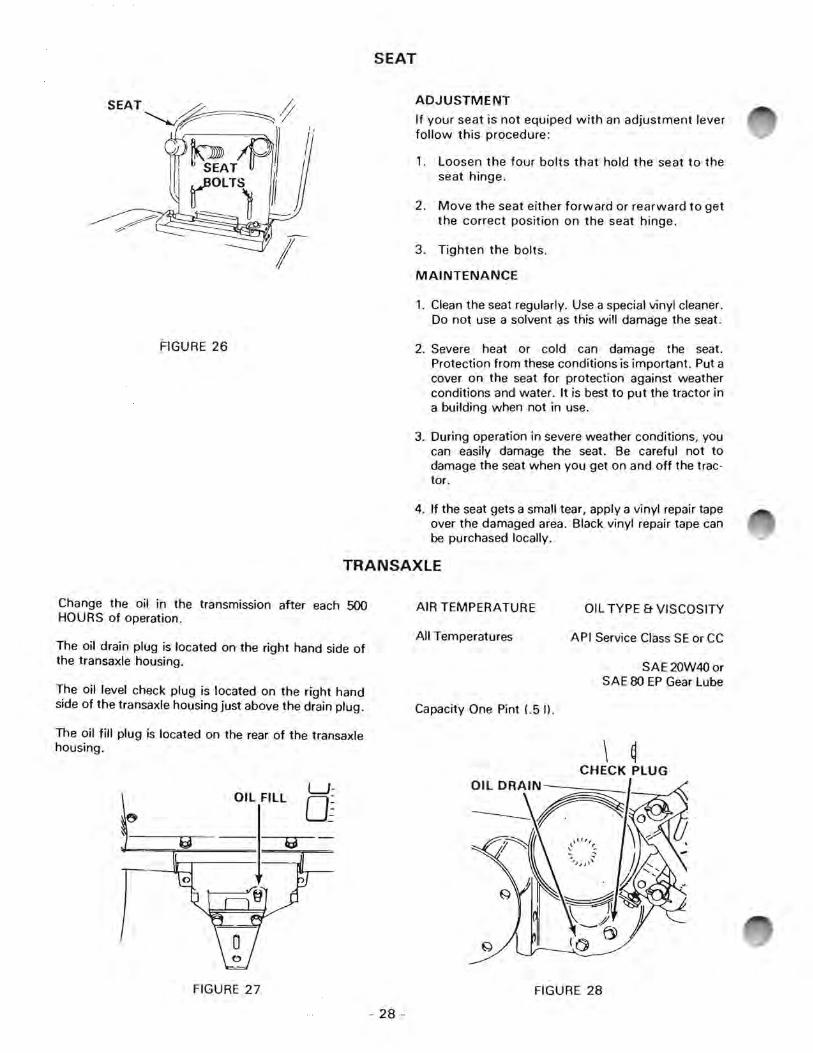
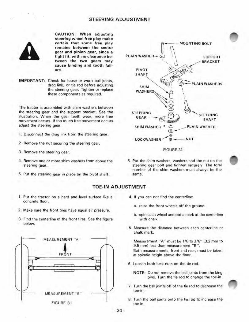

Printed in USA