Embed Size (px)
Citation preview

InfraStruxure Modular Remote Power Panel
Technical Specifications
PDPM144F
144kW, 400A, 208V, 72 Pole, 300mm
990-91036June 2017
www.schneider-electric.com

Schneider Electric Legal Disclaimer
The information presented in this manual is not warranted by Schneider Electric to be authoritative, error free,
or complete. This publication is not meant to be a substitute for a detailed operational and site specific
development plan. Therefore, Schneider Electric assumes no liability for damages, violations of codes,
improper installation, system failures, or any other problems that could arise based on the use of this
Publication.
The information contained in this Publication is provided as is and has been prepared solely for the purpose of
evaluating data center design and construction. This Publication has been compiled in good faith by Schneider
Electric. However, no representation is made or warranty given, either express or implied, as to the
completeness or accuracy of the information this Publication contains.
IN NO EVENT SHALL SCHNEIDER ELECTRIC, OR ANY PARENT, AFFILIATE OR SUBSIDIARY COMPANY
OF SCHNEIDER ELECTRIC OR THEIR RESPECTIVE OFFICERS, DIRECTORS, OR EMPLOYEES BE
LIABLE FOR ANY DIRECT, INDIRECT, CONSEQUENTIAL, PUNITIVE, SPECIAL, OR INCIDENTAL
DAMAGES (INCLUDING, WITHOUT LIMITATION, DAMAGES FOR LOSS OF BUSINESS, CONTRACT,
REVENUE, DATA, INFORMATION, OR BUSINESS INTERRUPTION) RESULTING FROM, ARISING OUT,
OR IN CONNECTION WITH THE USE OF, OR INABILITY TO USE THIS PUBLICATION OR THE CONTENT,
EVEN IF SCHNEIDER ELECTRIC HAS BEEN EXPRESSLY ADVISED OF THE POSSIBILITY OF SUCH
DAMAGES. SCHNEIDER ELECTRIC RESERVES THE RIGHT TO MAKE CHANGES OR UPDATES WITH
RESPECT TO OR IN THE CONTENT OF THE PUBLICATION OR THE FORMAT THEREOF AT ANY TIME
WITHOUT NOTICE.
Copyright, intellectual, and all other proprietary rights in the content (including but not limited to software, audio,
video, text, and photographs) rests with Schneider Electric or its licensors. All rights in the content not expressly
granted herein are reserved. No rights of any kind are licensed or assigned or shall otherwise pass to persons
accessing this information.
This Publication shall not be for resale in whole or in part.

Contents
Safety .............................................................................. 1
Important Safety Instructions . . . . . . . . . . . . . . . . . . . . . . . . . . . . . . . 1
Personnel requirements . . . . . . . . . . . . . . . . . . . . . . . . . . . . . . . . . . . 1
Electromagnetic compatibility . . . . . . . . . . . . . . . . . . . . . . . . . . . . . . 1
Safety precautions . . . . . . . . . . . . . . . . . . . . . . . . . . . . . . . . . . . . . . . 1
Technical Data................................................................. 2
Overview . . . . . . . . . . . . . . . . . . . . . . . . . . . . . . . . . . . . . . . . . . . . . . . . 2
Cabinet . . . . . . . . . . . . . . . . . . . . . . . . . . . . . . . . . . . . . . . . . . . . . . . . . 2
Power Distribution Features . . . . . . . . . . . . . . . . . . . . . . . . . . . . . . . 2
Configuration . . . . . . . . . . . . . . . . . . . . . . . . . . . . . . . . . . . . . . . . . . . 2
Options . . . . . . . . . . . . . . . . . . . . . . . . . . . . . . . . . . . . . . . . . . . . . . . . 3
Maintenance Clearance . . . . . . . . . . . . . . . . . . . . . . . . . . . . . . . . . . . 3
Modbus . . . . . . . . . . . . . . . . . . . . . . . . . . . . . . . . . . . . . . . . . . . . . . . . . 3
The Network Management Card . . . . . . . . . . . . . . . . . . . . . . . . . . . . . 4
NMC1 or NMC2 . . . . . . . . . . . . . . . . . . . . . . . . . . . . . . . . . . . . . . . . . . 4
Alarms . . . . . . . . . . . . . . . . . . . . . . . . . . . . . . . . . . . . . . . . . . . . . . . . . 4
Connections . . . . . . . . . . . . . . . . . . . . . . . . . . . . . . . . . . . . . . . . . . . . 4
Compliance...................................................................... 5
Approvals. . . . . . . . . . . . . . . . . . . . . . . . . . . . . . . . . . . . . . . . . . . . . . . . 5
Regulatory Agency Approval. . . . . . . . . . . . . . . . . . . . . . . . . . . . . . . . 5
Specifications.................................................................. 6Maximum input conductor size . . . . . . . . . . . . . . . . . . . . . . . . . . . . . 7
Drawings.......................................................................... 8
System one line diagram . . . . . . . . . . . . . . . . . . . . . . . . . . . . . . . . . . . 8
Internal View . . . . . . . . . . . . . . . . . . . . . . . . . . . . . . . . . . . . . . . . . . . . . 9
Right side . . . . . . . . . . . . . . . . . . . . . . . . . . . . . . . . . . . . . . . . . . . . . . 9
Remote Power Panel PDPM144F Technical Data 1

Options........................................................................... 10
Compatible PDMs . . . . . . . . . . . . . . . . . . . . . . . . . . . . . . . . . . . . . . . 10
What the Module Number means . . . . . . . . . . . . . . . . . . . . . . . . . . . 10
PDMs compatible with the RPP . . . . . . . . . . . . . . . . . . . . . . . . . . . . 10
Additional Options . . . . . . . . . . . . . . . . . . . . . . . . . . . . . . . . . . . . . . . 12
Seismic kit (SYOPT300) . . . . . . . . . . . . . . . . . . . . . . . . . . . . . . . . . . 12
Cable troughs . . . . . . . . . . . . . . . . . . . . . . . . . . . . . . . . . . . . . . . . . . 12
Extender cables . . . . . . . . . . . . . . . . . . . . . . . . . . . . . . . . . . . . . . . . . 13
Offset Baying brackets . . . . . . . . . . . . . . . . . . . . . . . . . . . . . . . . . . . 13
Warranty Information .................................................... 14
Warranty and Service Contracts . . . . . . . . . . . . . . . . . . . . . . . . . . . . 14
Standard warranty . . . . . . . . . . . . . . . . . . . . . . . . . . . . . . . . . . . . . . . 14
Additional service contracts . . . . . . . . . . . . . . . . . . . . . . . . . . . . . . 14
Limited Factory Warranty . . . . . . . . . . . . . . . . . . . . . . . . . . . . . . . . . 15
One-Year Factory Warranty . . . . . . . . . . . . . . . . . . . . . . . . . . . . . . . 15
Terms of Warranty . . . . . . . . . . . . . . . . . . . . . . . . . . . . . . . . . . . . . . . 15
Assignment of Warranties . . . . . . . . . . . . . . . . . . . . . . . . . . . . . . . . 15
Drawings, Descriptions . . . . . . . . . . . . . . . . . . . . . . . . . . . . . . . . . . . 15
Exclusions . . . . . . . . . . . . . . . . . . . . . . . . . . . . . . . . . . . . . . . . . . . . . 15
Warranty Claims . . . . . . . . . . . . . . . . . . . . . . . . . . . . . . . . . . . . . . . . 16
Remote Power Panel PDPM144F Technical Data2

Safety
Important Safety InstructionsPersonnel requirementsElectrical equipment should only be installed, operated, serviced, and maintained by qualified personnel. No responsibility is assumed by Schneider Electric for any consequences arising out of the use of this material.
A qualified person is one who has skills and knowledge related to the construction, installation, and operation of electrical equipment and has received safety training to recognize and avoid the hazards involved.
Electromagnetic compatibility
Safety precautions
DANGERHAZARD OF ELECTRIC SHOCK, EXPLOSION, OR ARC FLASH
• This product must be installed according to the specifications and requirements as defined by Schneider Electric. No responsibility is assumed by Schneider Electric if these requirements are not respected.
• After the RPP has been electrically wired, do not start up the system. Start-up must only be performed by Schneider Electric.
• The RPP must also be installed according to local and national regulations.
Failure to follow these instructions will result in death or serious injury.
NOTICEInstallation restrictions or additional measures may be needed to prevent electromagnetic disturbance.
DANGERHAZARD OF ELECTRIC SHOCK, EXPLOSION, OR ARC FLASH
• Install this product in a temperature controlled area free from conductive contaminants and humidity.
• Install this product on a non-flammable, level, and solid surface (e.g. concrete) that can support the weight of the system.
• The product is not designed for and must therefore not be installed in the following unusual operating environments:- Damaging fumes- Mixtures of corrosive gases, or conductive or radiant heat from other sources.- Moisture, abrasive dust, steam or in an excessively damp environment- Fungus, insects, vermin- Salt-laden air or contaminated cooling refrigerant- Pollution degree higher than 2 according to IEC 60664-1- Exposure to abnormal vibrations, shocks, and tilting- Exposure to direct sunlight, heat sources, or strong electromagnetic fields
Failure to follow these instructions will result in death or serious injury.
1Remote Power Panel PDPM144F Technical Data

Technical Data
OverviewThe Modular Remote Power Panel (RPP), PDPM144F, simplifies power distribution management by output metering, branch current/circuit monitoring and auto-detection by the StruxureWare data center infrastructure management options. When demand rises and expansion becomes necessary, simply plug in a new Power Distribution Module (PDM). The factory-assembled modules can be installed in a few minutes and include the circuit breaker, power cord, and power connection. There are multiple power ratings and power cord lengths for low to high power for compatibility and easy installation.
The Modular RPP is the source of amperage for the distribution, housing the power backplane, the main circuit monitoring bus, and the support structure for the PDMs.
CabinetThe frame is constructed of 14 gauge formed steel for maximum strength. All exterior panels and corner posts on the frame are powder coated for durability and an attractive finish. The front and rear doors are constructed of 18 gauge steel, and the side panels are constructed of 20 gauge steel. The front and back doors include a key latch for safety and security. The side panels lock with a separate key. Access to this key should be limited to certified electricians who have received the appropriate Schneider Electric training for working on this equipment or an Schneider Electric Field Service Engineer.
Power Distribution Features• The RPP can accommodate up to 24 PDMs.
• Backplane with standard outlets: enable quick addition of new circuits, minimizing downtime.
• The backplane assembly forms the entire electrical enclosure. Backplane covers isolate empty backplanes for safety.
• Cable management inside the panel frame does not require working among live conductors.
• Integrated Monitoring: While the PowerView display provides information locally at the RPP, a Network Management Card relays vital information to the monitoring platform of choice, simplifying the task of monitoring power usage and enabling remote control of the system through a web interface, StruxureWare management option, or your building management system. The system monitors many functions including the aggregate current draw.
• Add a circuit in minutes with no tools: The RPP automatically recognizes the module type, ampacity, cord length, and breaker size, simplifying load balancing and circuit addition.
• Up to 72 poles of three-phase power are distributed to the load by scalable PDMs.
• PDMs are available with multiple cable lengths. Locking connector plugs on the output cables secure connections to downstream equipment.
ConfigurationPower may be applied via the top or the bottom of the RPP. (NOTE: The RPP does not have a transformer and does not require a side car if power will be brought from the bottom of the unit.)
Double barrel lugs are provided to accommodate 4/0 AWG to 500 kcmil conductors.
2Remote Power Panel PDPM144F Technical Data

Options• A Seismic kit (SYOPT300) is available for additional stability in areas where seismic activity is
prevalent.
• Overhead troughs can be attached to the top of the unit in order to direct, organize, and conceal the cables.
• Extender cables for select PDM’s. Extender cables are not available in North America.
• Offset Baying brackets made of 16 gauge steel are used to secure the RPP to another enclosure in the row.
NOTE: Roof Height adapters are not compatible with the RPP. The mounting holes do not align.
Maintenance ClearanceRecommended service clearance unless national state and local codes supersede:
ModbusUse the Configure Modbus menu to set up communications between the equipment and the building management system.
Modbus communication is available at the console port (RS23 DB-9 connector).
• Non-configurable settings for the serial port: no parity, 8 data bits, 1 stop bit.
NOTE: An RS232 to RS485 converter (not provided) must be used to connect to a building management system.
To communicate RS-232 to the RPP through the console port, the RS232 to RS485 converter must be configured as a DTE device with Send Data Control rather than RTS control (most converters are DCE, some can be ordered as DTE). Some devices like the Omega Model 285 Superverter support DCE/DTE selection with a switch. Other devices such as those produced by B&B Electronics require a zero ohm resistor re-position to configure as a DCE device (see the device datasheet for details). RTS or SD selection is generally accomplished with a jumper. An appropriate RS-232 cable like the APC 940-0024D is also required.
The console port can be configured to run at either 9600 or 19200 baud. This must match the Building Management System or Modbus network transfer rate.
Most serial converters are capable of either 4-wire or 2-wire Modbus connections. The PDU is designed to handle 2-wire, half-duplex communication. For a 2-wire, half-duplex connection, jumper connectors should be placed between R+ & T+, and R- & T-. Then the modbus + wire is connected to R+/T+ and the - wire is connected to R-/T-. Some converters offer dip switches to accomplish the jumper connections.
NOTE: All RS232 to RS485 converters tested relied on a power supply that plugs into 110V AC wall receptacle.
NOTE: There is a known modbus polarity labeling ambiguity between converters, so if the modbus communication isn’t successful, try reversing the 2-wire connection.
Top 7.87 in. (200mm) minimum
Front 39.4 in. (1000mm) minimum
Rear 39.4 in. (1000mm) minimum
Side* Minimum service clearance per national, state, and local codes
* When possible, it is recommended to have clearance on the right side of the RPP to allow for service of certain internal components (metering boards).
3Remote Power Panel PDPM144F Technical Data

The Network Management CardNMC1 or NMC2Some RPPs have been updated from NMC1 to NMC2. It is important to check which Network Management Card is installed in your RPP before attempting a firmware upgrade. An attempt to update the NMC with incompatible firmware will generate a “Transfer Failed” notification.
RPPs currently using NMC1 can be upgraded to NMC2.
Benefits of NMC2:
• Password security
• RADIUS based remote authentication support, in addition to a selection of security protocols including TLS, SCP, for secure monitoring and control of an individual RPP via web browser, command line interface, or SNMP
• IPv6 ready
• Improved processing speeds in comparison to NMC1
Alarms• High Module Current
• High Subfeed Current
• High Total Output Current
• High Output Voltage
• Low Module Current
• Low Subfeed Current
• Low Total Output Current
• Low Output Voltage
• Maximum Module Current
• Maximum Subfeed Current
• Max Total Output Current
• Max Output Voltage
• Minimum Module Current
• Minimum Subfeed Current
• Modular Distribution Communication
• Module Breaker Open
• Output Frequency
• Subfeed Breaker Open
ConnectionsA Cat-5 cable is plugged into the RJ-45 connector on the unit. Connect the other end of the cable to a local computer or a network hub.
4Remote Power Panel PDPM144F Technical Data

Compliance
ApprovalsCertified by VDE to IEC 60439-1 Listed (US), UL, cUL (Canada) by Underwriters Laboratories Inc. to UL 60950, and OSHPD
Circuit breakers and conductor ampacity are derated in accordance with the national electrical code and IEC 60364-5-53.
Regulatory Agency ApprovalThis equipment has been tested and found to comply with the limits for a Class A digital device, pursuant to Part 15 of the FCC Rules. These limits are designed to provide reasonable protection against harmful interference, when the equipment is operated in a commercial environment. This equipment generates, uses, and can radiate radio frequency energy and, if not installed and used in accordance with the Installation Guide, may cause harmful interference to radio communications. Operation of this equipment in a residential area is likely to cause harmful interference in which case the user will be required to correct the interference at his own expense.
This Class A digital apparatus complies with Canadian ICES-003. Cet appareil numérique de la classe A est conforme à la norme NMB-003 du Canada.
This is a Class A Product. In a domestic environment this product may cause interference in which case the user may be required to take adequate measures.
5Remote Power Panel PDPM144F Technical Data
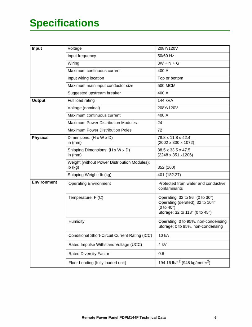
Specifications
Input Voltage 208Y/120V
Input frequency 50/60 Hz
Wiring 3W + N + G
Maximum continuous current 400 A
Input wiring location Top or bottom
Maximum main input conductor size 500 MCM
Suggested upstream breaker 400 A
Output Full load rating 144 kVA
Voltage (nominal) 208Y/120V
Maximum continuous current 400 A
Maximum Power Distribution Modules 24
Maximum Power Distribution Poles 72
Physical Dimensions: (H x W x D)in (mm)
78.8 x 11.8 s 42.4(2002 x 300 x 1072)
Shipping Dimensions: (H x W x D)in (mm)
88.5 x 33.5 x 47.5(2248 x 851 x1206)
Weight (without Power Distribution Modules):lb (kg) 352 (160)
Shipping Weight: lb (kg) 401 (182.27)
Environment Operating Environment Protected from water and conductive contaminants
Temperature: F (C) Operating: 32 to 86° (0 to 30°)Operating (derated): 32 to 104°(0 to 40°)Storage: 32 to 113° (0 to 45°)
Humidity Operating: 0 to 95%, non-condensingStorage: 0 to 95%, non-condensing
Conditional Short-Circuit Current Rating (ICC) 10 kA
Rated Impulse Withstand Voltage (UCC) 4 kV
Rated Diversity Factor 0.6
Floor Loading (fully loaded unit) 194.16 lb/ft2 (948 kg/meter2)
6Remote Power Panel PDPM144F Technical Data
Maximum input conductor sizeFor North America, if supplied by a 400 A circuit breaker, it is recommended that conductors are sized in accordance with the following table.
NOTES:CCC = Current-Carrying Conductors Ø = Phase conductorAWG = American Wire Gauge N = Neutral conductor(2) = two conductors per terminal G = Ground conductorkcmils (MCM) = Thousands of Circular Mils
For countries outside of North America, if supplied by a 400 A circuit breaker, it is recommended that conductors are sized in accordance with the following table.
NOTES:Ø = Phase conductor PVC = Polyvinyl3-chlorideN = Neutral conductor XLPE = Cross-linked polyethylenePE = Protective Earth conductor EPR = Ethylene propylene rubber
400 A, 75°C Conductors
Wiring System Copper Aluminum
3 CCC, 30°C AmbientØ&N = 500 MCMG = 3 AWG
Ø&N = (2) 4/0 AWG G = (2) 3 AWG
4 CCC, 30°C AmbientØ&N = (2) 4/0 AWGG = (2) 3 AWG
Ø&N = (2) 350 kcmilG = (2) 1 AWG
400 A, Conductors
Install. Method
Copper, PVC Insulation, 30°C Ambient mm²
Copper, XLPE or EPR Insulation, 30°C
Ambient mm²
Aluminum, PVC Insulation,
30°C Ambient mm²
Aluminum, XLPE or ERP Insulation,
30°C Ambient mm²
B1 Ø&N = (2) 95 PE = (2) 50
Ø&N = 240 PE = 120
Ø&N = (2) 150 PE = (2) 95
Ø&N = (2) 95 PE = (2) 50
B2 Ø&N = (2) 120 PE = (2) 70
Ø&N = (2) 95 PE = (2) 50
Ø&N = (2) 240 PE = (2) 120
Ø&N = (2) 120 PE = (2) 70
C Ø&N = 240 PE = 120
Ø&N = 185 PE = 95
Ø&N = (2) 150 PE = (2) 95
Ø&N = (2) 95 PE = (2) 50
E Ø&N = 240 PE = 120
Ø&N = 185 PE = 95
Ø&N = (2) 120 PE = (2) 70
Ø&N = 240 PE = 120
F (Trefoil) Ø&N = 185 PE = 95
Ø&N = 150 PE = 95
Ø&N = (2) 95 PE = (2) 50
Ø&N = 240 PE = 120
F (Flat) Ø&N = 185 PE = 95
Ø&N 120PE = 70
Ø&N = (2) 95 PE = (2) 50
Ø&N = 185 PE = 95
Distribution Details
Device ID Rating Type Make Model Rated Short Circuit Current
CB-1 5A 3 Pole Breaker Square D by Schneider Electric
MGN61426 10kA Symmetrical
Module-X 20A Power Distribution Module 3 Pole Breaker, 3, 5-Wire Cable with L21-20 Receptacle
Schneider Electric See “Compatible PDMs” on page 10
10kA Symmetrical
7Remote Power Panel PDPM144F Technical Data

Drawings
System one line diagramNOTE: An Emergency Power Off (EPO) circuit breaker, installed between mains power and the RPP, is recommended but not provided.
8Remote Power Panel PDPM144F Technical Data

Internal ViewRight side(Covers removed) Cables shown only for a few modules.
9Remote Power Panel PDPM144F Technical Data

Options
Compatible PDMs All Power Distribution Modules and extender cables are not part of this SKU and must be ordered separately.
What the Module Number means
PDMs compatible with the RPP
PDM1320L5-3P-x:
# Cords 3Compatible Rack PDU types
Compatible Rack PDU SKUs
Voltage 120V Basic AP7530, AP9551, AP9564
Amperage 20 A Metered AP7830, AP7801, AP8830, AP8930J, AP8833J
(Qty) PCircuit Breakers
(3) 1P Switched AP7930, AP7901, AP8930, AP8930J
(Qty) Connector
(3) 3 wire NEMA L5-20R
Metered by Outlet with Switching n/a
PDM3520L2120-xxx:
# Cords 1Compatible Rack PDU types
Compatible Rack PDU SKUs
Voltage 120V Basic AP7562, AP7592, AP7563, AP7593, AP7564, AP7594
Amperage 20 A Metered AP7862, AP7892, AP7863, AP7893, P8861, AP8862, AP8863
(Qty) PCircuit Breakers
(3) 1P Switched AP7960, AP7990, AP8961, AP8962
(Qty) Connector
(1) 5 wire NEMA L21-20
Metered by Outlet AP8461
Metered by Outlet with Switching AP8661
PDM3520L2120-1040
CABLE LENGTH IN CENTIMETERSTYPE OF RECEPTICLEBREAKER RATING IN AMPERENUMBER OF WIRESBREAKER POLESPOWER DISTRIBUTION MODULE
10Remote Power Panel PDPM144F Technical Data

PDM3530L2130-xxx
# Cords 1Compatible Rack PDU types
Compatible Rack PDU SKUs
Voltage 120V Basic n/a
Amperage 30 A Metered AP8865
(Qty) PCircuit Breakers
(3) 1P Switched AP8965
(Qty) Connector
(1) 5 wire NEMA L21-30
Metered by Outlet with Switching n/a
PDM3450CS50-xxx
# Cords 1Compatible Rack PDU types
Compatible Rack PDU SKUs
Voltage 208V Basic AP7568, AP7598, AP7569, AP7599, AP7567A, AP7516
Amperage 50 A Metered AP8868, AP7869, AP7899, AP7867A
(Qty) PCircuit Breakers
(1) 3P Switched AP7968, AP7998
(Qty) Connector
(1) 4wireCS50
Metered by Outlet with Switching n/a
PDM3460IEC309-xxx
# Cords 1Compatible Rack PDU types
Compatible Rack PDU SKUs
Voltage 208V Basic n/a
Amperage 60 A Metered AP8866, AP8867
(Qty) PCircuit Breakers
(1) 3P Switched n/a
(Qty) Connector
(1) 4wire (3P+PE)
IEC 309 60A
Metered by Outlet with Switching n/a
PDM2330L6-xx-yyy:
# Cords 1Compatible Rack PDU types
Compatible Rack PDU SKUs
Voltage 208V Basic AP7541, AP9570, AP9571A
Amperage 60 A Metered AP8841, AP7811
(Qty) PCircuit Breakers
(1) 2P Switched AP8941, AP7911A
(Qty) Connector
(1) 3wire NEMA L6-30R
Metered by Outlet AP8441
Metered by Outlet with Switching AP8641
11Remote Power Panel PDPM144F Technical Data

Additional OptionsSeismic kit (SYOPT300) Special floor brackets are available for additional stability in areas where seismic activity is prevalent.
Cable troughs Overhead troughs can be attached to the top of the unit in order to direct, organize, and conceal the cables.
pdx1
175a
FRONT
REAR
pdx1
173a
12Remote Power Panel PDPM144F Technical Data

Extender cables Extender cables are available only for select PDM’s. Extender cables are not available in North America.
Offset Baying bracketsBrackets made of 16 gauge steel are used to secure the RPP to another enclosure in the row.
pdx1
174a
13Remote Power Panel PDPM144F Technical Data

Warranty Information
Warranty and Service ContractsStandard warrantyPDPM144F comes with a standard one year repair or replace parts only warranty.
The Standard Warranty is upgraded to include Travel and Labor when a Start Up Service contract is purchased.
Additional service contracts Start up service: Standard start up service provides 5x8 scheduling with the optional upgrade to 7x24 scheduling available to provide a Certified Field Service Engineer for Installation of the unit.
Warranty extension: An on site warranty extension is available in 1 or 2 year increments for concurrent service only. A factory trained technician will arrive on site to diagnose or repair the system. Next Business Day Response is standard with an option to upgrade to 4 hour or 8 hour response in many locations. This warranty includes parts, travel and labor.
Preventive Maintenance: Provides a scheduled visit by a factory trained technician to perform an examination of your system designed to ensure optimal performance. A standard preventive maintenance contract provides 5x8 scheduling with the optional upgrade to 7x24 scheduling available.
An off hours scheduling option is available to service your system when it is least likely to impact your productivity.
Advantage Plans: Advantage Plans cover non-concurrent service and provide your system the service it needs to operate at peak performance and with maximum availability. Plans include:
• Tech support
• Next business day on site response
• Preventive maintenance (Standard and Plus)
• Remote monitoring service (Prime and Ultra)
– Ultra includes parts, labor and travel.
– Plus and Prime offer discounted rates on parts,
• Upgrade to 8 hour or 4 hour on site response is available in many locations.
14Remote Power Panel PDPM144F Technical Data

Limited Factory WarrantyOne-Year Factory WarrantyThe limited warranty provided by Schneider Electric in this Statement of Limited
Factory Warranty applies only to products you purchase for your commercial or
industrial use in the ordinary course of your business.
Terms of WarrantySchneider Electric warrants that the product shall be free from defects in materials and workmanship for a period of one year from the date of product start-up when start-up is performed by Schneider Electric-authorized service personnel and occurs within six months of the Schneider Electric shipment date. This warranty covers repairing or replacing any defective parts including on-site labor and travel. In the event that the product fails to meet the foregoing warranty criteria, the warranty covers repairing or replacing defective parts at the sole discretion of Schneider Electric for a period of one year from the shipment date. For Schneider Electric cooling solutions, this warranty does not cover circuit breaker resetting, loss of refrigerant, consumables, or preventive maintenance items. Repair or replacement of a defective product or part thereof does not extend the original warranty period. Any parts furnished under this warranty may be new or factoryremanufactured. Non-transferable Warranty This warranty is extended to the first person, firm, association or corporation (herein referred to by “You” or “Your”) for whom the Schneider Electric product specified herein has been purchased. This warranty is not transferable or assignable without the prior written permission of Schneider Electric.
Assignment of WarrantiesSchneider Electric will assign you any warranties which are made by manufacturers and suppliers of components of the Schneider Electric product and which are assignable. Any such warranties are assigned “AS IS” and Schneider Electric makes no representation as to the effectiveness or extent of such warranties, assumes no responsibility for any matters which may be warranted by such manufacturers or suppliers and extends no coverage under this Warranty to such components.
Drawings, DescriptionsSchneider Electric warrants for the warranty period and on the terms of the warranty set forth herein that the Schneider Electric product will substantially conform to the descriptions contained in the Schneider Electric Official Published Specifications or any of the drawings certified and agreed to by contract with Schneider Electric if applicable thereto (“Specifications”). It is understood that the Specifications are not warranties of performance and not warranties of fitness for a particular purpose.
ExclusionsSchneider Electric shall not be liable under the warranty if its testing and examination disclose that the alleged defect in the product does not exist or was caused by end user or any third person misuse, negligence, improper installation or testing. Further, Schneider Electric shall not be liable under the warranty for unauthorized attempts to repair or modify wrong or inadequate electrical voltage or connection, inappropriate on-site operation conditions, corrosive atmosphere, repair, installation, start-up by non-Schneider Electric designated personnel, a change in location or operating use, exposure to the elements, Acts of God, fire, theft, or installation contrary to Schneider Electric recommendations or specifications or in any event if the Schneider Electric serial number has been altered, defaced, or removed, or any other cause beyond the range of the intended use.
THERE ARE NO WARRANTIES, EXPRESS OR IMPLIED, BY OPERATION OF LAW OR OTHERWISE, OF PRODUCTS SOLD, SERVICED OR FURNISHED UNDER THIS AGREEMENT OR IN CONNECTION HEREWITH. SCHNEIDER ELECTRIC DISCLAIMS ALL IMPLIED WARRANTIES OF MERCHANTABILITY, SATISFACTION AND FITNESS FOR A PARTICULAR PURPOSE. SCHNEIDER ELECTRIC EXPRESS WARRANTIES WILL NOT BE ENLARGED, DIMINISHED, OR AFFECTED BY AND NO OBLIGATION OR LIABILITY WILL ARISE OUT OF, SCHNEIDER ELECTRIC RENDERING OF TECHNICAL OR OTHER ADVICE OR SERVICE IN CONNECTION WITH THE PRODUCTS. THE FOREGOING WARRANTIES AND REMEDIES ARE EXCLUSIVE AND IN LIEU OF ALL OTHER WARRANTIES AND REMEDIES. THE
15Remote Power Panel PDPM144F Technical Data

WARRANTIES SET FORTH ABOVE CONSTITUTE SCHNEIDER ELECTRIC SOLE LIABILITY AND PURCHASER’S EXCLUSIVE REMEDY FOR ANY BREACH OF SUCH WARRANTIES.SCHNEIDER ELECTRIC WARRANTIES RUN ONLY TO PURCHASER AND ARE NOT EXTENDED TO ANY THIRD PARTIES. IN NO EVENT SHALL SCHNEIDER ELECTRIC, ITS OFFICERS, DIRECTORS, AFFILIATES OR EMPLOYEES BE LIABLE FOR ANY FORM OF INDIRECT, SPECIAL, CONSEQUENTIAL OR PUNITIVE DAMAGES, ARISING OUT OF THE USE, SERVICE OR INSTALLATION, OF THE PRODUCTS, WHETHER SUCH DAMAGES ARISE IN CONTRACT OR TORT, IRRESPECTIVE OF FAULT, NEGLIGENCE OR STRICT LIABILITY OR WHETHER SCHNEIDER ELECTRIC HAS BEEN ADVISED IN ADVANCE OF THE POSSIBILITY OF SUCH DAMAGES, SPECIFICALLY, SCHNEIDER ELECTRIC IS NOT LIABLE FOR ANY COSTS, SUCH AS LOST PROFITS OR REVENUE, LOSS OF EQUIPMENT, LOSS OF USE OF EQUIPMENT, LOSS OF SOFTWARE, LOSS OF DATA, COSTS OF SUBSTITUANTS, CLAIMS BY THIRD PARTIES, OR OTHERWISE. NO SALESMAN, EMPLOYEE OR AGENT OF SCHNEIDER ELECTRIC IS AUTHORIZED TO ADD TO OR VARY THE TERMS OF THIS WARRANTY. WARRANTY TERMS MAY BE MODIFIED, IF AT ALL, ONLY IN WRITING SIGNED BY AN SCHNEIDER ELECTRIC OFFICER AND LEGAL DEPARTMENT.
Warranty ClaimsCustomers with warranty claims issues may access the SCHNEIDER ELECTRIC worldwide customer support network through the SCHNEIDER ELECTRIC website: http://www.schneider-electric.com. Select your country from the country selection pull-down menu. Open the Support tab at the top of the web page to obtain contact information for customer support in your region.
16Remote Power Panel PDPM144F Technical Data

Radio Frequency InterferenceChanges or modifications to this unit not expressly approved by the party responsible for
compliance could void the user’s authority to operate this equipment.
USA—FCC
This equipment has been tested and found to comply with the limits for a Class A digital device, pursuant to
part 15 of the FCC Rules. These limits are designed to provide reasonable protection against harmful
interference when the equipment is operated in a commercial environment. This equipment generates, uses,
and can radiate radio frequency energy and, if not installed and used in accordance with this user manual,
may cause harmful interference to radio communications. Operation of this equipment in a residential area is
likely to cause harmful interference. The user will bear sole responsibility for correcting such interference.
Canada—ICES
This Class A digital apparatus complies with Canadian ICES-003.
Cet appareil numérique de la classe A est conforme à la norme NMB-003 du Canada.
Japan—VCCI
This is a Class A product based on the standard of the Voluntary Control Council for Interference by
Information Technology Equipment (VCCI). If this equipment is used in a domestic environment, radio
disturbance may occur, in which case, the user may be required to take corrective actions.
この装置は、情報処理装置等電波障害自主規制協議会(VCCI)の基準に基づくクラス A 情報技術装置で
す。この装置を家庭環境で使用すると、電波
妨害を引き起こすことがあります。この場合には、使用者が適切な対策を講ずるように要求されることが
あります
Taiwan—BSMI警告使用者 :這是甲類的資訊產品 , 在居住的環境中使用時 , 可能會造成射頻干擾 , 在這種情況下 , 使用者會被要求採取某些適當的對策。

Worldwide Customer SupportCustomer support for this or any other product is available at no charge in any of the following ways:
• Visit the Schneider Electric Web site to access documents in the Schneider Electric Knowledge Base and to submit customer support requests.
– www.schneider-electric.com (Corporate Headquarters)Connect to localized Schneider Electric Web sites for specific countries, each of which provides customer support information.
– www.schneider-electric.com/support/Global support searching Schneider Electric Knowledge Base and using e-support.
• Contact the Schneider Electric Customer Support Center by telephone or e-mail.
– Local, country-specific centers: go to www.schneider-electric.com > Support > Operations around the world for contact information.
For information on how to obtain local customer support, contact the representative or other distributors from whom you purchased your product.
© 2017 Schneider Electric. All rights reserved. Schneider Electric, APC, the APC logo, and InfraStruxure are trademarks owned by Schneider Electric Industries, S.A.S. or its affiliated companies.