Embed Size (px)
Citation preview

//20-Dec-18 1
Infrastructure Projects
Signalling - Shared Learning
18/02: March 2018 – December 2018

/20-Dec-18 2
Introduction
This Shared Learning document details key issues and
incidents that have occurred on Signalling Projects
between March 2018 and December 2018 and provides
the key learning points associated with them.
It is intended for distribution within the Network Rail
Signalling community and the Supply Chain in order to
raise awareness of the learning points within, and to
enable best practice to be applied throughout all of our
signalling activities.

/20-Dec-18 3
IP Addresses
Background
During post commissioning works it was discovered that the
axle counter “B” link was not communicating due to a
duplication of the IP address. Investigation showed that the IP
address for the interlocking processor “A” and “B” network
was duplicated in the Axle Counter Processor (ACP).
A latent defect in the system diagnostic software masked the
error initially, showing both A and B systems as operating
correctly.
Key Learning
All design, project engineering and testing
staff should be aware of the criticality of
correct IP addressing, understanding that
duplication or error can result in a loss of
duplicated systems.

/20-Dec-18 4
Soak testing
Background
A Signal Module failed shortly after commissioning
causing train delays. The module had generated a
number of alarms during soak test. Constrained
programme issues meant that installation works
were continuing during the soak test period. The
genuine alarms were not being distinguished from
alarms caused by installation works and therefore
not being fully investigated prior to commissioning.
Key Learning
During the soak test period project staff need to
monitor ALL alarms and diagnostic information. This
will in turn enable the team to react to alarms
(identifying erroneous alarms caused by planned
works) and rectify any issues prior to
commissioning.

/20-Dec-18 5
Computer Based Route Setting
Background
A number of issues have been experienced with
computer based route setting systems, causing an
increase in delay minutes attributable to the route
setting functionality.
• Failed update of software, attempts caused
whole system failure.
• Intermittent failures on A and B links, leading to
a momentary loss of route setting sub-areas.
• Instances of timetable not downloading or
unpacking correctly requiring reboot of the
Timetable Server.
Key Learning
Issues are subject to investigation.
However, it is important to use test systems that
have both the target hardware and firmware
versions.

/20-Dec-18 6
Permanent Speed Restriction AWS
Background
A train approaching a signal did not receive an AWS
warning when passing over an associated Permanent
Speed Restriction (PSR) magnet, for a diverging route.
The erroneous suppression of the PSR magnet only
occurs during, or after, a diverging route including flashing
aspect sequence is set after the main route has been
taken and released, where the magnet is correctly
suppressed.
The magnet suppression function would have been
latched for the main, straight route, but the latch is not
removed by manual button pull, but is by TORR (Train
Operated Route Release).
A data error affected this signal and others in the same
interlocking.
This scenario required a manual Operations intervention
until the data was changed.
Key Learning
Designers need to consider carefully where the introduction of complex controls are absolutely necessary.
Data designers and testers need to understand how latch controls are set and unset.

/20-Dec-18 7
Operating Irregularity – Data Omission
Background
A train completing a reversing move on single line at a
station received an AWS Code 7 (nothing received) on a
suppressed magnet which should have given a warning.
This is a legitimate non-signalled turnback move (no
starting signal is provided at the station in question for the
turn back move).
On investigation it was noted the requirement for this route
had been included in the project Operational
Requirements Specification (ORS). During the data
development this requirement had been omitted from the
interlocking data.
Key Learning
Projects need to understand all requirements listed in the
ORS need to be included, these requirements are made
through consultation with key stakeholders in Operations.
All requirements need to be effectively communicated
through to data designers and testers.

/20-Dec-18 8
IBJ Bonding
Background
After a successful resignalling commissioning, a proving
train on a single line suffered traction problems (loss of
line light) and could not complete its journey.
On investigation it was discovered a number of bonds
which should have bonded around, a now redundant IBJ
had not been fully installed.
The project had received a completion certificate for this
work stating all planned works had been successfully
commissioned. .
This omission could have caused a serious safety incident
and did incur a significant amount of delay minutes.
Key Learning
Robust assurance checks are essential to ensure the
integrity of the infrastructure prior to handback and
completion of the required paperwork.
Traction bonding errors and omissions can have a serious
safety impact.
/20-Dec-18 9
Power Supply Source
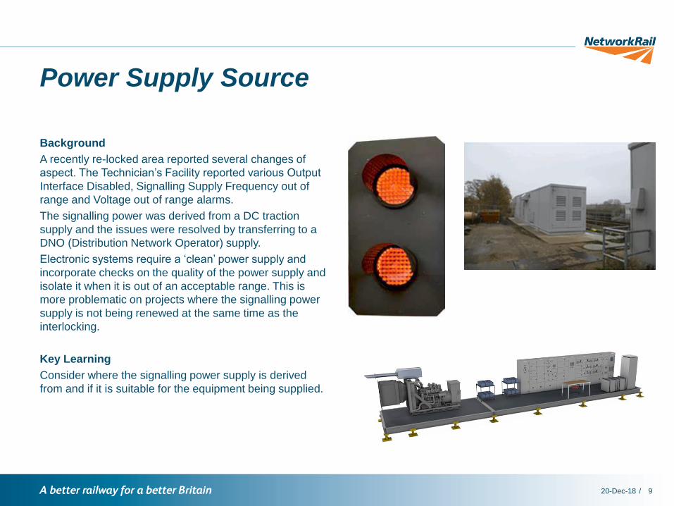
Background
A recently re-locked area reported several changes of
aspect. The Technician’s Facility reported various Output
Interface Disabled, Signalling Supply Frequency out of
range and Voltage out of range alarms.
The signalling power was derived from a DC traction
supply and the issues were resolved by transferring to a
DNO (Distribution Network Operator) supply.
Electronic systems require a ‘clean’ power supply and
incorporate checks on the quality of the power supply and
isolate it when it is out of an acceptable range. This is
more problematic on projects where the signalling power
supply is not being renewed at the same time as the
interlocking.
Key Learning
Consider where the signalling power supply is derived
from and if it is suitable for the equipment being supplied.
/20-Dec-18 10
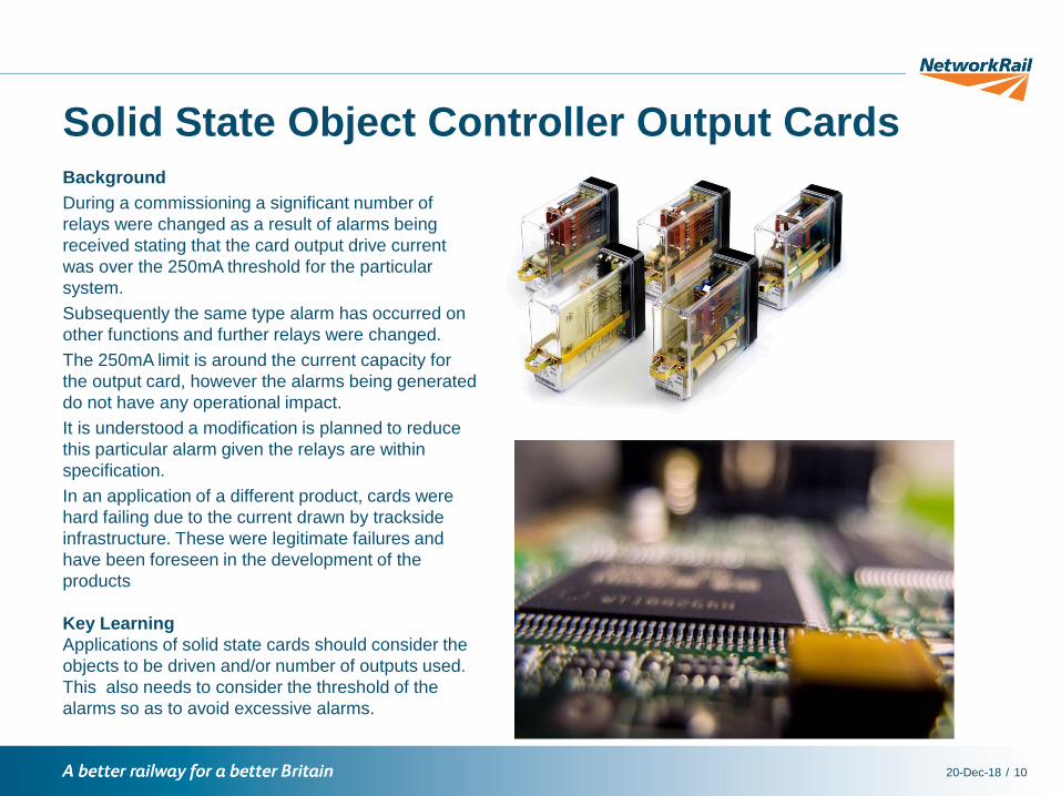
Solid State Object Controller Output CardsBackground
During a commissioning a significant number of
relays were changed as a result of alarms being
received stating that the card output drive current
was over the 250mA threshold for the particular
system.
Subsequently the same type alarm has occurred on
other functions and further relays were changed.
The 250mA limit is around the current capacity for
the output card, however the alarms being generated
do not have any operational impact.
It is understood a modification is planned to reduce
this particular alarm given the relays are within
specification.
In an application of a different product, cards were
hard failing due to the current drawn by trackside
infrastructure. These were legitimate failures and
have been foreseen in the development of the
products
Key Learning
Applications of solid state cards should consider the
objects to be driven and/or number of outputs used.
This also needs to consider the threshold of the
alarms so as to avoid excessive alarms.

/20-Dec-18 11
Cross Boundary DataBackground
A standard data construct used in a new interlocking caused a signal in an adjacent RRI interlocking to act as a “double
red”. Investigation revealed a track circuit occupied function combined with an aspect lit function that was not required.
The project remit did include detail on the specific conditions to be used in this instance, but this was not implemented.
With the original functionality, junction signal 103 would step up to single yellow when a second train was routed via
the divergence after the first train had cleared the overlap of 107. With the new functionality, junction signal 103 is
prevented from stepping up to single yellow until the first train has cleared ABC track as well. This inhibits the flashing
yellow sequence provided by 101 signal, until the first train has cleared ABC track causing a consequential delay if the
following train is also routed via the divergence.
Key Learning
Designers and testers need to ensure consistency between data and wiring in fringe designs.
103101
107 3001
ABC(T)
RRI New interlocking
ABC(T) is entirely within RRI

/20-Dec-18 12
Signal Alignment
Background
Post commissioning reports of poor signal visibility or dim
signals have been received on a number of projects, due
to signal aspects not being aligned in accordance with
the Signal Sighting Assessment Form (SSAF). The
alignment is particularly critical on 3° narrow beam LED
signals.
Key Learning
NB165 published in October 2018 gives clear guidance
on the responsibilities of the Installer, Tester and Sighting
Committee in the set up and assurance of alignment for
signals and indicators.
It is considered best practice for the Signal Sighting Chair
to complete the final sighting checks as part of the
commissioning.
Information on this is available in:
NR/L2/SIG/10158 Appendix C; Signals – Configuration,
Specification and Construction Guidance.
Signalling Works Test Specification -
NR/L2/SIG/30014/D120/TS7-91 Inspection to SSF and
Signal Sighting.

/20-Dec-18 13
Level Crossing Fail to Raise
Background
A fault was reported that an MCB CCTV level
crossing’s barriers had failed to auto-raise, after the
passage of a train..
A route was set in the Up direction followed by a
Down direction route, which was then cancelled.
The train traversed in the Up direction, but the auto
raise control was still waiting for the Down train and
the barriers failed to raise.
The auto raise function had operated as designed,
requiring either the Down train to run and cancel the
route or the Signaller to manually raise the barriers.
The difference in operation was following a signalling
renewal from a conventional relay system to a
Computer Based Interlocking system.
This unusual sequence of events and how to manage
it had not been communicated to the signallers.Key Learning
Designers need to understand and communicate the implications of how the data has been written.
Differences in operation to be briefed to Signallers and contained within the signaller training material, as part of the
project training.

/20-Dec-18 14
Clarity of Responsibility
Background
An operational incident required interrogation of a recently
commissioned voice recorder (VR). However, the
workstation had been commissioned without the voice
recorder channels being configured.
Investigation found that there was confusion regarding
who was responsible for the VR configuration and test,
and the Entry Into Service plan did not have sufficient
detail on the VR.
Key Learning
Responsibility demarcations should be clearly
documented and briefed to all project staff.
Where tests are being performed by a third party they
shall be defined and included within testing
documentation.

/20-Dec-18 15
Crimp / Crimping Quality
Background
A project recently discovered numerous poorly
made Q crimp connections. These have been
supplied in location cases for several other
projects.
Key Learning
Test crimps should be made available to testers,
and quality checks undertaken.
All tools should be fully calibrated and have up
to date certificates.

/20-Dec-18 16
Further Information
For any further details or information please contact:
Chris Ruddy: Senior Project Engineer (Process & Capability)
Tel: 07799 336772
E-mail: [email protected]