Embed Size (px)
Citation preview

©Dreisilker Electric Motors, Inc. 1 http://www.dreisilker.com
Infrared Analysis of Electrical Machines and Controls
Howard W Penrose, Ph.D., CMRP
Vice President, Engineering and Reliability Services
Dreisilker Electric Motors, Inc.
Jay Malo
Level 2 Thermographer
Dreisilker Electric Motors, Inc.
Introduction
Infrared analysis is a powerful tool for reliability, maintenance and troubleshooting of electrical equipment. In the case of electric machines, it can be used both in the field to detect electrical and mechanical issues as well as part of the evaluation system for electric motors through the
repair process.
One of the important aspects behind this tool is the ability to observe the problem visually using pictures and/or video. This assists in quickly identifying and also showcasing potential or existing problems. Unlike many of the other testing and predictive maintenance technologies,
even the inexperienced observer can see the difference between good and bad.
Does this mean that the average technician can pick up an infrared camera and start a program? No, there are a lot of things that a good thermographer must be able to identify. For example, in some of the present television ghost hunting reality shows you will see the stars walking around
and all of a sudden they see something and all the excitement starts. To the experienced thermographer watching these shows, they will note that the spot where the ‘ghost’ was seen is a
shiny surface, glass, or plastic. What they are really seeing is a reflection of themselves or the camera crew or equipment. Another simple demonstration is to place your hand against the wall for about ten seconds and then point the camera at it. For a long time after (I had shown the
handprint up to 15 minutes after) you can see the image of the hand.
The infrared thermographer must understand what can and will reflect, how to calibrate the device, and how to set the camera for specific applications. It is also important to understand the surroundings. In a case where concern was brought up related to piping overheating, it later was
discovered that the sun had been shining on the piping and, when the piping was tested, even after the sun had dropped enough that the pipe was in shadow, it still appeared hot. There was
never any real issue. Basically, surfaces will give different results depending on the angle and lighting. The infrared
thermographer must be able to adjust and view the source from different angles in order to identify whether or not there is a heating issue. Otherwise, the reflection of a fluorescent light on
a shiny surface may result in over-reaction and troubleshooting of a problem that does not exist. Equally critical is the understanding that infrared only sees the surface temperature. For
instance, you cannot view a loose connection through a metal door. The air in between acts as an insulator. If you were to see heating through the door then a problem exists that is past the point
of urgency! Yet, we find in many cases, companies go in and quote a low price to walk along and point a camera at a door instead of opening cabinets or using infrared windows.

©Dreisilker Electric Motors, Inc. 2 http://www.dreisilker.com
Field Applications
The most common use for infrared thermography in the field for an electric motor is the electrical circuit. This is performed by viewing the connections and electrical components.
Depending upon company rules, and how they address NFPA 70E, this may be completed by having someone open the cabinet wearing appropriate flash protection, or through the use of infrared windows. Part of the consideration, by some, is the initial cost associated with the
installation of infrared windows, which can be a considerable up-front cost. However, the amount of time necessary, as well as manpower, drops considerably through their use.
The infrared window may be made of several types of crystal or plastics that are nearly invisible to infrared light. They will normally have a cover installed in order to provide explosion
protection as part of the cabinet. However, once the cover is moved, that protection is reduced. The more important part of using the window is that the thermographer or assistant is not
opening the door and disturbing/triggering an explosion. There are some basic adjustments the thermographer must make to compensate for the filtering of infrared through the window.
Figure 1: Infrared Thermographer Working with Open Cabinet
So far as direct exposure, the NFPA 70E provides approach distances and Personal Protective Equipment (PPE) requirements depending upon the system. Many companies have had Flash
Surveys performed that identify the hazard associated with opening a loaded cabinet. This is important, as the equipment should be loaded to at least 40% for thermography to be effective. Additionally, the thermographer should not be the technician that is opening the cabinet and
should have freedom of movement while scanning from a safe distance.
The most common method of evaluating equipment is to evaluate the component by comparing it to the ambient temperature. This is a distinctive approach as it does not require that the temperature be absolutely correct, just a correct delta between the component and background, or
between like components.
There are several industry standards for the severity of a problem related to the delta for ambient and for similar components. These can be found in Tables 1 and 2.
©Dreisilker Electric Motors, Inc. 3 http://www.dreisilker.com
Table 1: NETA Specification
Priority Delta between similar components and loads
Delta over ambient Recommendation
4 1-3 C 1-10 C Warrants investigation
3 4-15 C 11–20 C Repair as time permits
2 21-40 C Monitor until corrective action is accomplished
1 >15 C >40 C Repair immediately
Table 2: Mil-STD-2194
Priority Delta over ambient Recommendation
4 10-25 C Corrective measures required as scheduling permits
3 25-40 C Failure probable unless corrected
2 40-70 C Failure certain unless corrected
1 >70 C Failure imminent.
The Infrared Institute out of Burlington, New Jersey, produces a standard for infrared
thermography entitled, “Standard for Infrared Inspection of Electrical Systems & Rotating Equipment,” that includes the temperature limits for individual components as well as guidance for inspecting electric motors and related equipment.
Electrical Inspections
The most common use for infrared thermography in electric motor systems is the inspection of controls and connections to detect loose connections and high resistant joints. There are a few
things to consider when looking at electrical systems. These include: taking data from the correct angle(s); color and reflective surfaces; and, how heavily loaded the system is.
The last point is extremely important when considering the electrical system as the energy put out by a loose or damaged connection varies significantly by the amount of current passing
through it. Whether the system is AC or DC, the energy is based upon the I2R rule where the Watts (energy) can be calculated by the square of the current passing through a resistance. Watts
are viewed as heat energy. For example: if you have a resistance of 0.1 ohms and pass 100 Amps through it you will generate 1,000 Watts, or 1kW, worth of energy.
The conversion of Watts to the temperature measured in the infrared spectrum is complex and outside the scope of this paper. It is possible, but requires information on the materials involved,
surface areas, type of imaging system used, ambient conditions and the ability of the surfaces to radiate. Suffice to say that varying the load from measurement to measurement will yield different results. Taking measurements at similar loads when trending will result in data that can
be used for determining the potential hazard involved in loose connections. The thermographer, or guide, may use an ammeter to determine the loading of the system when data is being used for
predictive maintenance programs.

©Dreisilker Electric Motors, Inc. 4 http://www.dreisilker.com
Figure 2: Evaluation of a Loose Bus Connection
Figure 3: Overloaded Phase in Machine Contactor

©Dreisilker Electric Motors, Inc. 5 http://www.dreisilker.com
Figure 4: Loose Connection on Circuit Breaker for Lights
Figure 5: Loose Connection on Switch for Elevator
©Dreisilker Electric Motors, Inc. 6 http://www.dreisilker.com
Machine Inspections
Electric motors can be viewed with infrared. However, it is very difficult to detect problems in the stator, itself. Bearings, couplings and severe problems can be detected and a relation to
surface temperature and loading can be determined when performing periodic testing. It is important for the thermographer to note, as well, the color of motor paint.
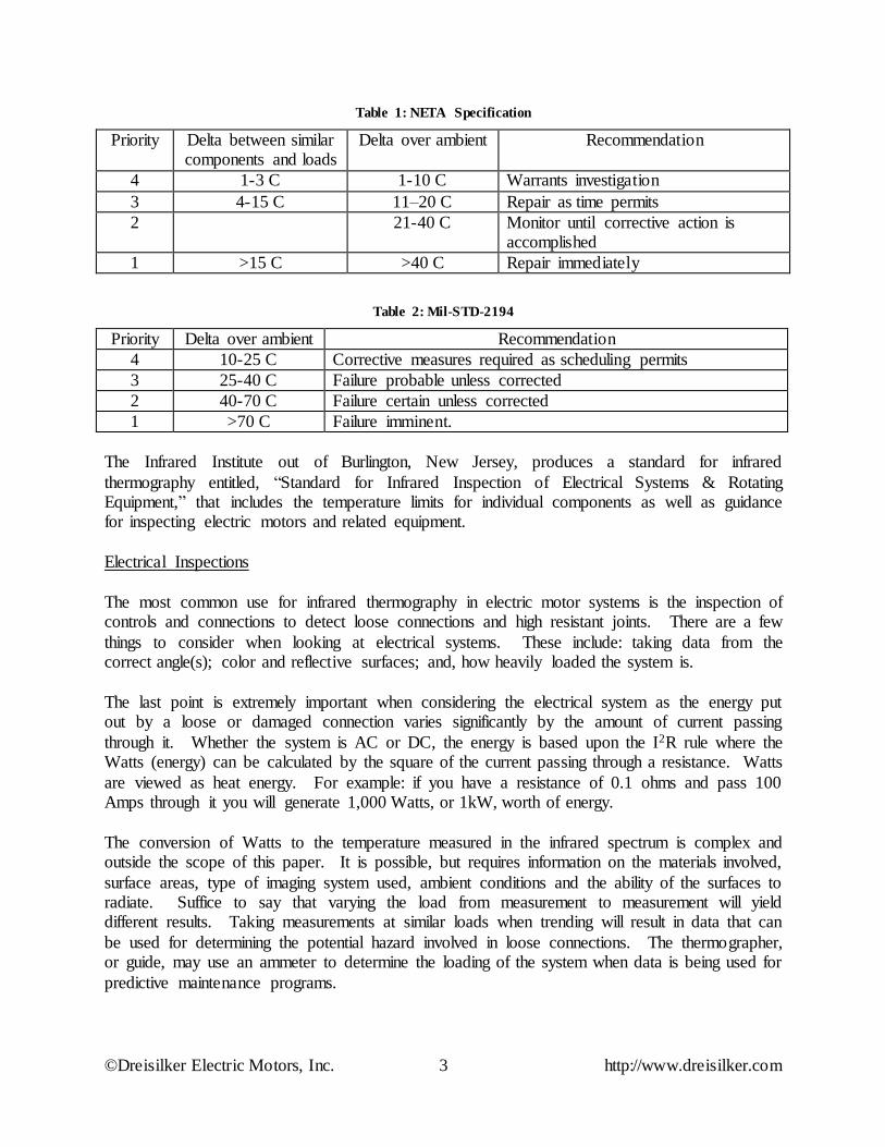
Figure 6: General Infrared Picture of a Motor
In Figure 6, an operating motor has been evaluated. What does this picture show? The motor is a TEFC (Totally Enclosed Fan Cooled) machine which results in the cooler end on the far left. The ‘white,’ which would indicate ‘hot,’ is towards the center of the motor. The orange color
throughout the rest of the motor indicates heat. The white is where the motor core is located and the differences in color relate to both the angle of the imager and an area made up of air (an
excellent thermal insulator) by the connection box. In effect, there is nothing wrong with this particular motor other than infrared thermography generating a colorful picture.
Bearing and coupling issues do stand out and can be quickly identified. Noting also in Figure 6, the coupling to the right and the shaft appear relatively ‘cool’ compared to the rest of the motor.
The coupling should be very close to ambient temperature. The shaft will be warmer close to the motor and cool as it approaches the coupling.
As shown in Figure 7, the ability to look at bearings and couplings is not limited to the electric motor but can also be performed for bearings and mechanical components on other rotating
machines. It is important to understand the application and if there are contact lip seals in the application.

©Dreisilker Electric Motors, Inc. 7 http://www.dreisilker.com
Figure 7: Pump Shaft
With DC machines, infrared allows you the ability to evaluate the condition of brushes by
looking at them from a different perspective. By their nature, brushes should be warm and give off infrared energy. If a brush is cooler than the rest in a DC machine, then it should be inspected to see if it is sticking in the brush box or if the spring tension is too loose.
Use of Infrared in the Repair Shop
Infrared also has its place in the motor repair shop. It can be used for multiple applications with the most common being testing rotor bars and hot spot testing of the stator during core loss
testing. For rotor bar testing, this is completed by using a core loss tester with special connections for the rotor shaft. In the case of a stator, either a core loss tester or loops of cable
are used to saturate the core to a range of .9 to 1.2 times the magnetic field capability of the core. With the rotor, several things will generate heat on the core:
Welds, balancing weights, keys and through-bolts will usually become hot;
Dirt and rust, which also may cause some sparking between laminations;
Significant shorted laminations;
Loose laminations; and,
©Dreisilker Electric Motors, Inc. 8 http://www.dreisilker.com
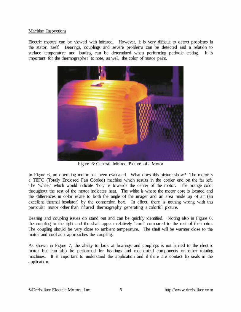
Broken rotor bars as the current passes through the core around the crack on the bar
versus through the rotor bar. When the cause of the high temperature is dirt and rust, when the current is de-energized the
temperature will drop rapidly. In the case of a lamination defect or broken rotor bar, the temperature will tend to drop slowly.
Figure 8: Broken Rotor Bar Note Spot Temperature is Greater than 223oC.
Once a rotor fault is found using infrared, then it becomes relatively simple to determine if it is something that can be repaired, such as a poor weld or braise, or if the rotor bars need to be
replaced. As with the stator, a rotor has a hot spot temperature limitation of 10oC and the whole rotor core
should not increase more than a few degrees during a three minute hot spot test.
©Dreisilker Electric Motors, Inc. 9 http://www.dreisilker.com
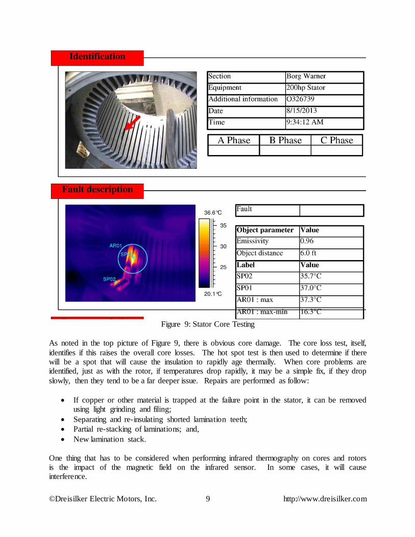
Figure 9: Stator Core Testing
As noted in the top picture of Figure 9, there is obvious core damage. The core loss test, itself,
identifies if this raises the overall core losses. The hot spot test is then used to determine if there will be a spot that will cause the insulation to rapidly age thermally. When core problems are identified, just as with the rotor, if temperatures drop rapidly, it may be a simple fix, if they drop
slowly, then they tend to be a far deeper issue. Repairs are performed as follow:
If copper or other material is trapped at the failure point in the stator, it can be removed using light grinding and filing;
Separating and re-insulating shorted lamination teeth;
Partial re-stacking of laminations; and,
New lamination stack.
One thing that has to be considered when performing infrared thermography on cores and rotors is the impact of the magnetic field on the infrared sensor. In some cases, it will cause interference.
©Dreisilker Electric Motors, Inc. 10 http://www.dreisilker.com
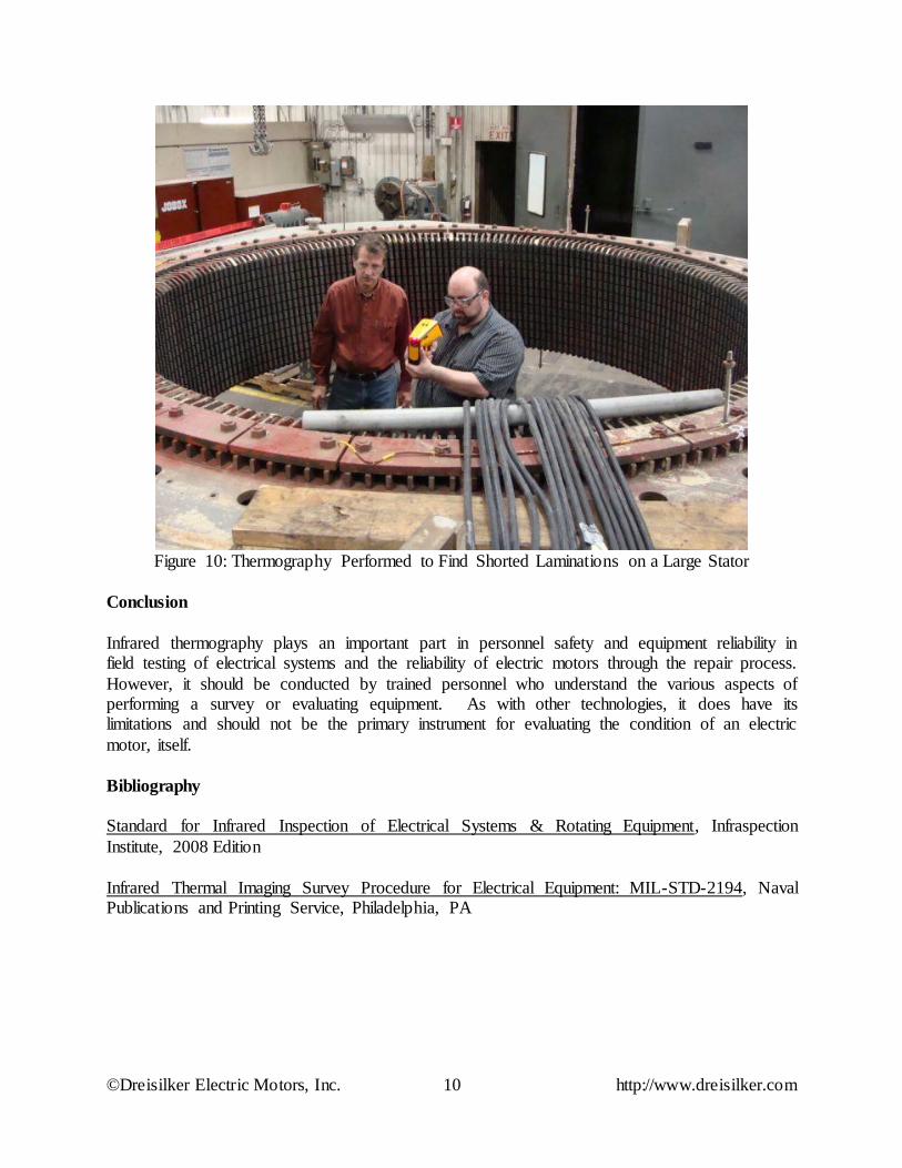
Figure 10: Thermography Performed to Find Shorted Laminations on a Large Stator
Conclusion
Infrared thermography plays an important part in personnel safety and equipment reliability in field testing of electrical systems and the reliability of electric motors through the repair process.
However, it should be conducted by trained personnel who understand the various aspects of performing a survey or evaluating equipment. As with other technologies, it does have its limitations and should not be the primary instrument for evaluating the condition of an electric
motor, itself.
Bibliography
Standard for Infrared Inspection of Electrical Systems & Rotating Equipment, Infraspection
Institute, 2008 Edition
Infrared Thermal Imaging Survey Procedure for Electrical Equipment: MIL-STD-2194, Naval Publications and Printing Service, Philadelphia, PA