Embed Size (px)
Citation preview

INFORMATION/COMMUNICATION RESOURCE REQUIREMENTS
Refer to Telecommunications Wiring Standards Appendix “C” on the following pages. The project is required to include FIU security camera and emergency call boxes and to provide high-speed, secure, wired and wireless connections to the FIU Network. In addition, the Project may also include data connectivity features such as sensors and displays for the Informed Traveler Program & Applications, and FDOT traffic camera and other traffic monitoring systems.

C-1
APPENDIX "C" - STANDARDS FOR TELECOMMUNICATIONS FACILITIES FOR NONRESIDENTIAL RESIDENTIAL LIFE BUILDINGS The purpose of this standard is to provide for the planning and installation of telecommunications facilities in new buildings and major renovations. This standard has been developed with little knowledge of the telecommunications equipment that subsequently will be installed. Therefore, the definitions included herewith are for generic telecommunications facilities that will support a multitude of rapidly changing telecommunications technologies in a multivendor and variable end user environment. This standard recognizes three fundamental concepts related to telecommunications and buildings:
(1) Buildings are dynamic. Renovation, remodeling and upgrading are more the rule than exception. This standard takes into account that change will occur.
(2) Building telecommunications systems and media are dynamic. As time passes both telecommunications equipment and media change considerably. This standard recognizes this fact and the facilities prescribed herein are capable of supporting a vast array of telecommunications systems and media.
(3) Telecommunications is more than telephones. Telecommunications is inclusive of a variety of building systems including data systems, environmental control, security, audio, television, sensing, alarms, emergency communications and much more.
Above all, this standard recognizes a fact of fundamental importance: if a building is to be properly designed, built and provisioned for telecommunications systems, it is imperative that the telecommunications design be incorporated during the architectural design phase. The FIU/UTS Infrastructure Department developed this document in accordance with industry specifications. It is the standard by which the University defines the physical facilities required for the provisioning of telecommunications systems for new buildings and major renovations to existing buildings. These specifications take into account the physical facilities such as the size and provisioning of telecommunications rooms, cable distance limitations, vertical and horizontal cabling considerations, number and size of conduits and numbers and types of information outlets. The general cabling requirements are not addressed, because FIU/UTS is solely responsible for the installation of all the telecommunications wiring in all FIU buildings and campuses.

C-2
APPENDIX “C” TABLE OF CONTENTS
1.0 GENERAL C - 3
2.0 CABLE PATHWAYS C - 3
2.1 INFORMATION OUTLETS C - 3
2.2 CONDUIT C - 4
3.0 OUTSIDE PLANT C - 5
3.1 DEFINITION DESCRIPTION C - 5
3.2 MANHOLES C - 6
DRAWINGS C – 7,8,9
C-3
1.0 GENERAL
1.1 RESPONSIBILITY - It is the responsibility of the project architect/engineer to ensure the inclusion of the standards for building telecommunications facilities into the design and construction documents for new and major renovation projects.
1.2 REFERENCES - In addition to the specifications included herewith the architect/engineer is
encouraged to refer to the following publications for guidance during the design of the communications infrastructure:
Building Industry Consulting Service International (BICSI); Telecommunications Distribution Methods Manual (Latest Edition).
Electronic Industries Association, Telecommunications Industry Association (EIA/TIA) Building Telecommunications Wiring Standards.
NFPA's National Electric Code (NEC).
FIU/UTS Infrastructure Department.
1.3 COORDINATION - Prior to the start of any telecommunications related work, the contractor shall coordinate the installation with the UTS/Infrastructure Department ..
2.0 CABLE PATHWAYS
2.1 INFORMATION OUTLETS
2.1.1 ELECTRICAL BOXES - Locations for information/wireless outlets must be
equipped with a 4 in. X 4 in. X 2.5-in. electrical box equipped with a mudring sized for the installation of a standard duplex outlet.
2.1.3.1 WATERPROOF BOXES- Outdoor wireless antenna, outdoor paging horns , and outdoor security cameras locations must be equipped with a 4 in. X 4 in. X 2.5-in waterproof box with blank cover.
2.1.2 MOUNTING HEIGHT - Electrical boxes installed for information outlets must be
placed at the same level as the adjacent duplex electrical receptacles or at least fifteen (15) inches above the finished floor. 2.1.2.1 Waterproof boxes for outdoor wireless antennas and emergency paging
horns installation heights will be provided to contractor after a site survey of building is conducted by UTS.

C-4
2.1.2.2 Electrical boxes installed for emergency call buttons shall be mounted 48 in. above finished floor by entrance.
2.1.2.3 Waterproof boxes for outdoor security camera locations will be determined
by UTS and Facilities after site survey is completed.
2.1.3 OUTDOOR WIRELESS AREAS shall have a minimum of one (1) information outlet location per access point, to be located above ceiling on the inside of the outside wall of building or structure.
2.1.4 OUTDOOR EMERGENCY PAGING HORNS shall have a minimum of (1) information
outlet location per horn, to be located on an outside wall of building or structure. 2.2 CONDUITS
2.2.1 A 1 inch EMT conduit must be installed from each information outlet electrical box
including indoor/outdoor wireless access point, emergency call buttons, security cameras, EMS, and emergency paging horn location and "stubbed" up above the ceiling level to cable tray. (Please see attached drawing, Fig. 2.2.1-A)
2.2.3 PULL BOXES - A pull box must be installed in sections of conduit longer than 100
ft. or containing more than two 90-degree bends or if there is a reverse bend in the run.
2.2.4 Minimum requirements for installed conduit, such as support, end protection, and
continuity, are found in appropriate electrical codes. 2.2.5 The inside radius of a bend in conduit must be at least 6 times the internal diameter.
When the conduit size is greater than 2 in. the inside radius must be at least 10 times the internal diameter of the conduit.
2.2.6 PULL CORDS - All conduits must have a fish tape or pull cord, rated for 200 lbs. of
pull force, and installed end-to-end. 2.2.7 ELEVATOR – A 1” conduit must be installed from each elevator equipment room to the nearest telecommunication room or cable tray.
Note: (1) Under no circumstances will flexible metallic conduit be used
for any telecommunication wiring. (2) Under no circumstances will any conduits be “daisy-chained”.
2.2.8 GROUNDING - A #6 THW ground cable shall be installed for each Outdoor Wireless Access Point location from the nearest Intermediate Closet (IC) or Telecommunications Room (TR) or nearest approved grounding source.

C-5
3.0 OUTSIDE PLANT
3.1 DEFINITION DESCRIPTION
3.1.1 All new building or structure construction planning must provide for connection of the building or structure to the campus telecommunications infrastructure.
3.1.2 CONDUIT SIZE - All direct buried conduits used to connect to the University
Telecommunications infrastructure must be 4” PVC, Schedule 40, unless it is deemed a different size be used.
3.1.3 NUMBER REQUIRED - The minimum number of conduits connecting the building
or structure must be at least 2 four-inch (2 - 4”) conduits. Note: More conduits might be needed depending on the size and utilization of the building or structure.
3.1.4 DEPTH - The top of the conduit bank must be buried at least 30 inches below the
ground surface and separated from other service structures as required for fiber optical cable under EIA/TIA specifications.
Separation of telecommunications conduits from other utilities shall meet the following guidelines:
Separation of Telecommunications Conduits from Other Utilities
Structure
Minimum Separation
Power or other conduit 3 inches in concrete 4 inches in masonry 12 inches in earth
Pipes (gas, oil, water) 6 inches when crossing pipe 12 inches when parallel to pipe
Power conduit terminated on poles Separate poles, if possible. If on same pole, 180 degree separation Preferable, but not less than 90 degrees.
The conduits must be placed in accordance with the requirements specified in the FIU building manual. In particular, special attention must be paid to the Telecommunications requirements in Appendix C.
3.1.5 DUCT BANK PROTECTION - Conduit must be encased in concrete when:
(1) Minimum conduit depth of 30 inches cannot be attained. (2) Conduits pass under roads, driveways, or railroad tracks. (3) Bend points are subject to movement.

C-6
Note: A detectable warning tape must be placed 18 inches above all duct banks (detectable: containing metallic tracings).
3.1.6 SLOPE - Underground conduit must be installed such that a slope exits at all points
of the run to allow drainage and prevent the accumulation of water. A drain slope of no less than .125 in. per foot is desirable.
3.2 MANHOLES (MAINTENANCE HOLES)
3.2.1 DESCRIPTION - A manhole (maintenance hole) is used to pull in and splice cables
in an underground, concealed manner. Manholes must be equipped with a sump, corrosion resistant pulling iron, cable racks, and manhole ladders. Concrete used for manholes must be of at least 3500 lb./in2 strength. All manholes must be properly grounded as required by BICSI. (Please refer to 1.2)
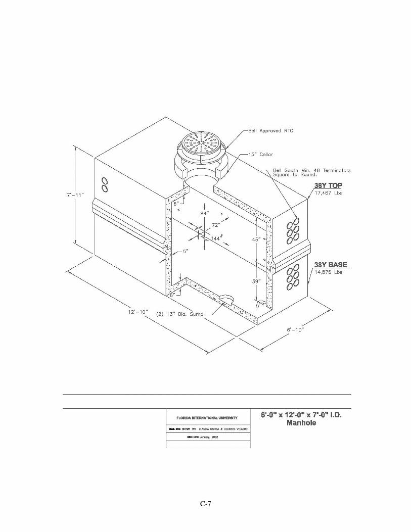
3.2.2 SIZE - Manholes must be sized at 6-ft. width X 12-ft. length X 7-ft. height, unless
specified by the UTS Project Manager. All manholes must be equipped with a round ring and cover, clearly labeled "TELECOM" or "TELEPHONE". (Please see attached drawing, Fig. 4.2.2-A)
3.2.3 WHERE REQUIRED - Manholes must be placed when the conduit section length
exceeds 500 ft, whenever a cable splice will be required, when bends exceed a total of 180 degrees or two bends, or the section length of conduit requires the pulling in of cable in two segments.
3.2.4 HANDHOLES are not an acceptable alternative to manholes described in section
4.2.1, 4.2.2. Handholes can only be used in place of manholes after consultation with and receipt of written approval from the UTS/Infrastructure Department. (Please see attached drawing, Fig. 4.2.4-A)
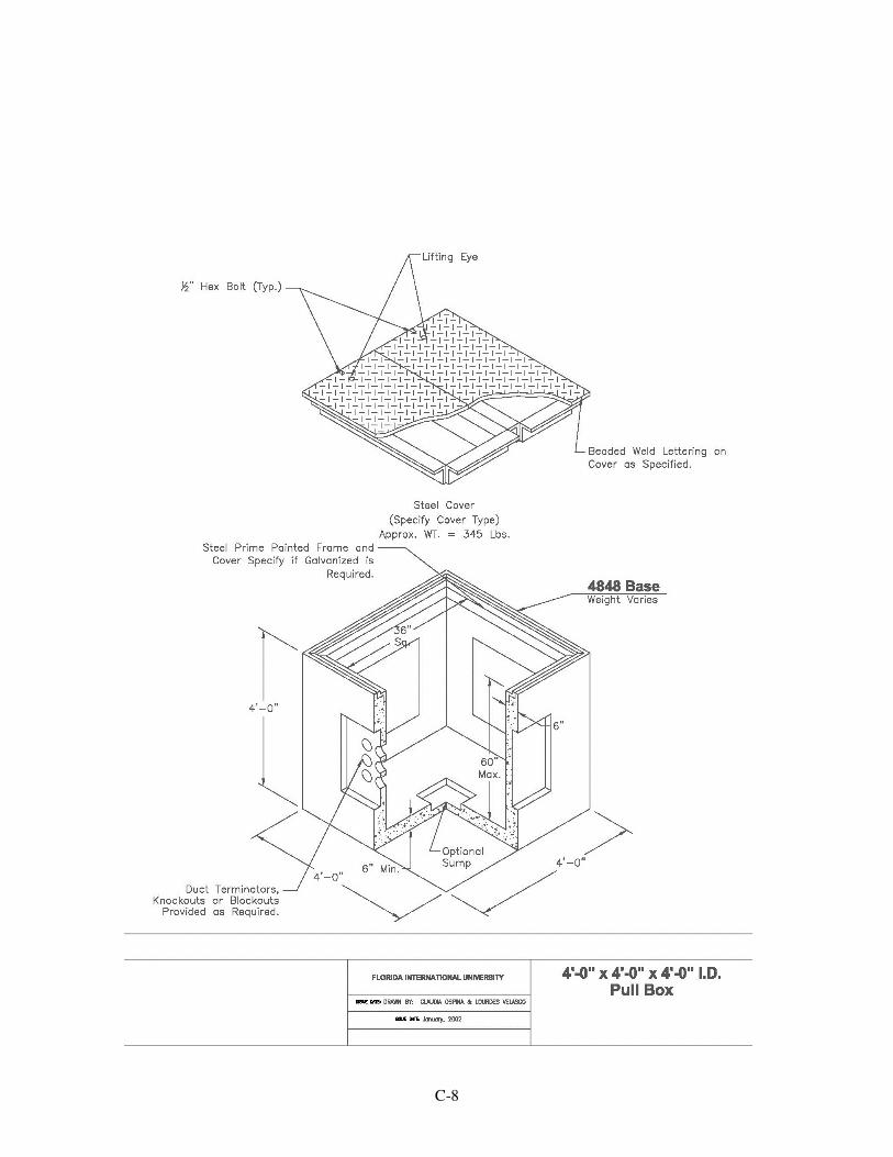
3.2.5 PULL POINTS - Wherever distances between manholes exceeds 200 feet or there
are more than two 90 degree bends in the conduit run, a 4’ x 4’ x 4’ pull box must be placed. The number of conduits going in and out of the pull box shall not exceed six. Under no circumstances shall a pull box replace a manhole. (Please see attached drawing, Fig. 4.2.5-A)
3.2.6 POSITIONING OF CONDUITS IN MANHOLE - Conduits entering a manhole shall
do so only through the manhole walls designed for conduit penetration. Under no circumstances shall the structural integrity of the manhole be compromised. Note: Conduits being added to a manhole must be placed as deep as possible in
order to accommodate future expansion of ductbanks and guarantee maximum utilization of the manhole.
C-7
C-8