Embed Size (px)
Citation preview

- 1 -
INFORMATIONAL PROPOSAL (For information only, not to be used for bidding)
NEBRASKA DEPARTMENT OF ROADS LETTING DATE: October 23, 2014 __________________________________________________ | | | U.S. Department of Transportation | | Federal Highway Administration | | Full Oversight Project | |_________________________________________________| CALL ORDER: 450 CONTRACT ID: 4707 CONTROL NO./SEQ. NO.: 42707 /000 PROJECT NO.: URB-5436(5) TENTATIVE START DATE: 06/01/15 CONTRACT TIME: 225 WORKING DAYS LOCATION: CAPITAL AVENUE, WEBB-WHEELER, GRAND ISLAND IN COUNTY: HALL BIDDER GROUP 1 GRADING GROUP 3 CONCRETE PAVEMENT GROUP 4 CULVERTS GROUP 4A WATER MAIN GROUP 4B SANITARY SEWER GROUP 5 SEEDING GROUP 8B ELECTRICAL GROUP 10 GENERAL ITEMS
THIS PROPOSAL CONTAINS A DBE GOAL OF 6.0 %. SEE SPECIAL PROVISIONS FOR GROUP TIES NOTES ___________________________________________________________________ | | | THE TOTAL AMOUNT OF WORK WHICH WILL BE ACCEPTED IN | | THIS LETTING IS LIMITED TO $__________________________. | |___________________________________________________________________| ___________________________________________________________________ | | | THE NUMBER OF _______________ CONTRACTS WHICH WILL BE | | ACCEPTED IN THIS LETTING IS LIMITED TO _______________. | |___________________________________________________________________|

Project No. URB-5436(5)
- 2 -
NOTICE TO ALL BIDDERS To report bid rigging activities, call: 1-800-424-9071 The U.S. Department of Transportation (DOT) operates the above toll-free “hotline” Monday through Friday, 8:00 a.m. to 5:00 p.m. eastern time. Anyone with knowledge of possible bid rigging, bidder collusion, or other fraudulent activities should use the “hotline” to report such activities. The “hotline” is part of the DOT’s continuing effort to identify and investigate highway construction contract fraud and abuse and is operated under the direction of the DOT Inspector General. All information will be treated confidentially and caller anonymity will be respected.
LETTING QUESTIONS
Prior to the letting, any questions pertaining to the Special Provisions or the Plans for this project should be submitted to NDOR in a written format through the Bid Express (BidX) website at https://www.bidx.com/ne/lettings. Likewise, NDOR will post answers exclusively to the BidX website. All official answers will be identified as “Authorized by NDOR.” Questions will not be answered verbally.

Project No. URB-5436(5)
- 3 -

Project No. URB-5436(5)
- 4 -

Project No. URB-5436(5)
- 5 -

Project No. URB-5436(5)
- 6 -

Project No. URB-5436(5)
- 7 -

Project No. URB-5436(5)
- 8 -

Project No. URB-5436(5)
- 9 -

Project No. URB-5436(5)
- 10 -

Project No. URB-5436(5)
- 11 -

Project No. URB-5436(5)
- 12 -
Project No. URB-5436(5)
- 13 -
Project No. URB-5436(5)
- 14 -

Project No. URB-5436(5)
- 15 -

Project No. URB-5436(5)
- 16 -

Project No. URB-5436(5)
- 17 -

Project No. URB-5436(5)
- 18 -

Project No. URB-5436(5)
- 19 -

Project No. URB-5436(5)
- 20 -
General Decision Number: NE140031 01/03/2014 NE31 Superseded General Decision Number: NE20130031 State: Nebraska Construction Type: Highway Counties: Adams, Blaine, Buffalo, Clay, Custer, Franklin, Garfield, Greeley, Hall, Hamilton, Harlan, Howard, Kearney, Loup, Merrick, Nance, Nuckolls, Phelps, Sherman, Valley, Webster and Wheeler Counties in Nebraska. HIGHWAY CONSTRUCTION PROJECTS Modification Number Publication Date 0 01/03/2014 * ENGI0571-005 01/01/2013 Rates Fringes OPERATOR: Trencher..............$ 20.83 9.60 ---------------------------------------------------------------- * SUNE2011-027 08/29/2011 Rates Fringes CARPENTER........................$ 17.16 CEMENT MASON/CONCRETE FINISHER Adams, Blaine, Buffalo, Clay, Franklin, Garfield, Greeley, Hall, Hamilton, Harlan, Howard, Kearney, Loup, Merrick, Nance, Nuckolls, Phelps, Sherman, Valley Webster, Wheele Counties....................$ 14.06 Custer County...............$ 15.38 ELECTRICIAN, Includes Installation of Traffic Signals..........................$ 19.00 FENCE ERECTOR....................$ 12.83 HIGHWAY/PARKING LOT STRIPING: Laborer Adams, Blaine, Buffalo, Custer, Clay, Franklin, Garfield, Greeley, Hall, Hamilton, Harlan, Howard, Loup, Merrick, Nance, Nuckolls, Phelps, Sherman, Valley Webster, & Wheele Counties....................$ 11.49 Kearney County..............$ 12.00

Project No. URB-5436(5)
- 21 -
IRONWORKER, REINFORCING..........$ 17.93 LABORER: Common or General Adams County................$ 11.52 Blaine, Clay, Franklin, Garfield, Greeley, Howard, Kearney, Loup, Merrick, Nance, Phelps, Sherman, Webster & Wheeler Counties..$ 11.39 Buffalo County..............$ 9.43 Custer County...............$ 11.12 Hall County.................$ 12.79 Hamilton County.............$ 12.77 Harlan County...............$ 12.24 Nuckolls County.............$ 10.64 Valley County...............$ 11.13 LABORER: Landscape & Irrigation.......................$ 8.30 LABORER: Mason Tender - Cement/Concrete..................$ 9.75 LABORER: Traffic Control - Flagger and Cone/Barrel Setter Adams County................$ 8.75 Blaine, Clay, Custer, Franklin, Garfield, Greeley, Loup, Merrick, Nance, Nuckolls, Phelps, Webster & Wheeler Counties..$ 10.16 Buffalo County..............$ 10.97 Hall County.................$ 9.72 Hamilton County.............$ 9.65 Harlan County...............$ 11.96 Howard County...............$ 9.35 Kearney County..............$ 9.68 Sherman County..............$ 9.83 Valley County...............$ 11.15 LABORER Asphalt Raker...............$ 11.13 Operating Engineers: (Skid Loader)..........................$ 12.96 OPERATOR: Asphalt Plant.........$ 12.75 OPERATOR: Backhoe Loader Combo............................$ 14.33 OPERATOR: Broom/Sweeper.........$ 10.77 OPERATOR: Bulldozer.............$ 15.69 OPERATOR: Chain Saw.............$ 13.35

Project No. URB-5436(5)
- 22 -
OPERATOR: Compactor.............$ 10.05 OPERATOR: Crane Adams, Blaine, Buffalo, Custer, Clay, Franklin, Garfield, Greeley, Hall, Hamilton, Howard, Kearney, Loup, Merrick, Nance, Nuckolls, Phelps, Sherman, Valley Webster, & Wheele Counties....................$ 16.17 Harlan County...............$ 13.60 1.80 OPERATOR: Distributor...........$ 14.37 OPERATOR: Loader Adams, Blaine, Clay, Franklin, Garfield, Greeley, Hamilton, Howard, Kearney, Loup, Marrick, Nance, Nuckolls, Phelps, Sherman, Valley, Webster, Wheeler Counties............$ 14.68 Buffalo County..............$ 15.21 Custer County...............$ 17.58 Hall County.................$ 13.78 Harlan County...............$ 13.02 OPERATOR: Mechanic Adams, Blaine, Buffalo, Custer, Clay, Franklin, Garfield, Greeley, Hamilton, Harland, Howard, Kearney, Loup, Merrick, Nance, Nuckolls, Phelps, Sherman, Valley Webster, & Wheele Counties.............$ 15.42 Hall County.................$ 16.42 OPERATOR: Paver (Asphalt, Aggregate, and Concrete).........$ 12.35 OPERATOR: Roller Adams County................$ 12.16 Blaine, Buffalo, Custer, Clay, Franklin, Garfield, Greeley, Hall, Hamilton, Howard, Kearney, Loup, Merrick, Nance, Nuckolls, Phelps, Sherman, Webster, & Wheele Counties...........$ 12.00 Harlan County...............$ 12.86 Valley County...............$ 12.30 OPERATOR: Scraper Adams, Blaine, Buffalo, Custer, Clay, Franklin,

Project No. URB-5436(5)
- 23 -
Garfield, Greeley, Hall, Hamilton, Howard, Kearney, Loup, Merrick, Nance, Nuckolls, Phelps, Sherman, Valley Webster, & Wheele Counties....................$ 15.79 Harlan County...............$ 15.50 OPERATOR: Screed................$ 12.01 OPERATOR: Tractor Adams, Blaine, Buffalo, Custer, Clay, Franklin, Garfield, Greeley, Hamilton, Harland, Howard, Kearney, Loup, Merrick, Nance, Nuckolls, Phelps, Sherman, Valley Webster, & Wheele Counties.............$ 12.80 Hall County.................$ 13.73 OPERATOR: Grader/Blade Adams County................$ 18.25 Blaine, Buffalo, Custer, Clay, Franklin, Garfield, Greeley, Hamilton, Howard, Kearney, Loup, Merrick, Nance, Nuckolls, Phelps, Sherman, Webster & Wheeler Counties....................$ 15.51 Hall County.................$ 15.85 Harlan County...............$ 14.49 Valley County...............$ 15.48 POWER EQUIPMENT OPERATOR: (BACKHOE, EXCAVATOR, TRACKHOE) Adams, Blaine, Buffalo, Clay, Custer, Franklin, Garfield, Greeley, Hall, Hamilton, Howard, Kearney, Loup, Merrick, Nance, Nuckolls, Phelps, Sherman, Valley, Webster, Wheeler....$ 15.14 Harlan......................$ 14.36 1.71 TRUCK DRIVER (LOWBOY) Adams, Blaine, Buffalo, Custer, Clay, Franklin, Garfield, Greeley, Harland, Howard, Kearney, Loup, Merrick, Nance, Nuckolls, Phelps, Sherman, Valley Webster, & Wheele Counties....................$ 11.99 Hall County.................$ 13.20 Hamilton County.............$ 13.50

Project No. URB-5436(5)
- 24 -
TRUCK DRIVER, Includes Dump and Tandem Truck Adams County................$ 12.13 Blaine, Buffalo, Custer, Clay, Franklin, Garfield, Greeley, Harland, Kearney, Loup, Merrick, Nance, Nuckolls, Phelps, Sherman, Valley Webster,& Wheeler Counties....................$ 12.18 Hall & Howard Counties......$ 11.00 Hamilton County.............$ 13.58 TRUCK DRIVER: Oil Distributor Truck................$ 13.25 TRUCK DRIVER: Semi-Trailer Truck............................$ 11.25 TRUCK DRIVER: Water Truck.......$ 11.00 ---------------------------------------------------------------- WELDERS - Receive rate prescribed for craft performing operation to which welding is incidental. ================================================================ Unlisted classifications needed for work not included within the scope of the classifications listed may be added after award only as provided in the labor standards contract clauses (29CFR 5.5 (a) (1) (ii)). ---------------------------------------------------------------- The body of each wage determination lists the classification and wage rates that have been found to be prevailing for the cited type(s) of construction in the area covered by the wage determination. The classifications are listed in alphabetical order of "identifiers" that indicate whether the particular rate is union or non-union. Union Identifiers An identifier enclosed in dotted lines beginning with characters other than "SU" denotes that the union classification and rate have found to be prevailing for that classification. Example: PLUM0198-005 07/01/2011. The first four letters , PLUM, indicate the international union and the four-digit number, 0198, that follows indicates the local union number or district council number where applicable , i.e., Plumbers Local 0198. The next number, 005 in the example, is an internal number used in processing the wage determination. The date, 07/01/2011, following these characters is the effective date of the most current negotiated rate/collective bargaining agreement which would be July 1, 2011 in the above example.

Project No. URB-5436(5)
- 25 -
Union prevailing wage rates will be updated to reflect any changes in the collective bargaining agreements governing the rates. 0000/9999: weighted union wage rates will be published annually each January. Non-Union Identifiers Classifications listed under an "SU" identifier were derived from survey data by computing average rates and are not union rates; however, the data used in computing these rates may include both union and non-union data. Example: SULA2004-007 5/13/2010. SU indicates the rates are not union majority rates, LA indicates the State of Louisiana; 2004 is the year of the survey; and 007 is an internal number used in producing the wage determination. A 1993 or later date, 5/13/2010, indicates the classifications and rates under that identifier were issued as a General Wage Determination on that date. Survey wage rates will remain in effect and will not change until a new survey is conducted. ---------------------------------------------------------------- WAGE DETERMINATION APPEALS PROCESS 1.) Has there been an initial decision in the matter? This can be: * an existing published wage determination * a survey underlying a wage determination * a Wage and Hour Division letter setting forth a position on a wage determination matter * a conformance (additional classification and rate) ruling On survey related matters, initial contact, including requests for summaries of surveys, should be with the Wage and Hour Regional Office for the area in which the survey was conducted because those Regional Offices have responsibility for the Davis-Bacon survey program. If the response from this initial contact is not satisfactory, then the process described in 2.) and 3.) should be followed. With regard to any other matter not yet ripe for the formal process described here, initial contact should be with the Branch of Construction Wage Determinations. Write to: Branch of Construction Wage Determinations Wage and Hour Division U.S. Department of Labor 200 Constitution Avenue, N.W. Washington, DC 20210

Project No. URB-5436(5)
- 26 -
2.) If the answer to the question in 1.) is yes, then an interested party (those affected by the action) can request review and reconsideration from the Wage and Hour Administrator (See 29 CFR Part 1.8 and 29 CFR Part 7). Write to: Wage and Hour Administrator U.S. Department of Labor 200 Constitution Avenue, N.W. Washington, DC 20210 The request should be accompanied by a full statement of the interested party's position and by any information (wage payment data, project description, area practice material, etc.) that the requestor considers relevant to the issue. 3.) If the decision of the Administrator is not favorable, an interested party may appeal directly to the Administrative Review Board (formerly the Wage Appeals Board). Write to: Administrative Review Board U.S. Department of Labor 200 Constitution Avenue, N.W. Washington, DC 20210 4.) All decisions by the Administrative Review Board are final. ================================================================ END OF GENERAL DECISION
Project No. URB-5436(5)
- 27 -
SPECIAL PROVISIONS FOR
FEDERAL AID PROJECT NO. URB-5436(5)
GENERAL CONDITIONS
Bids for the work contemplated in this proposal form will be received by the Department of Roads of the State of Nebraska, for the City of Grand Island, Nebraska, at the office of the Nebraska Department of Roads in Room 104 of the Central Office Building at 1500 Highway 2 at Lincoln, Nebraska on October 23, 2014, until 1:30 P.M. a. Bids submitted by mail should be addressed to the Nebraska Department of Roads,
c/o Contract Lettings Section, P.O. Box 94759, Lincoln, NE 68509-4759. b. Bids submitted electronically over the internet, shall be submitted using www.bidx.com. The 2007 Edition of the Standard Specifications for Highway Construction, including all amendments and additions thereto effective at the date of the contract, are made a part of these Special Provisions, through reference. The Required Contract Provisions, Form FHWA 1273, (Rev. 5-12), and the Notice of Requirement for Affirmative Action to Ensure Equal Employment Opportunity and Standard Federal Equal Employment Opportunity Construction Contract Specifications dated November 3, 1980, are attached to and are a part of this proposal form. The Standard Labor Classifications and Descriptions for Highway Construction dated September 1, 1996, are made a part of these Special Provisions, through reference. The General Wage Decision issued under the Davis-Bacon and Related Acts is attached to and is a part of this proposal form. The attention of bidders is directed to the Required Contract Provisions covering subletting or assigning the contract. GROUPS 1, 3, 4, 4A, 4B, 5, 8B AND 10 ARE TIED TOGETHER AND BIDDING PROPOSAL FORMS FOR THIS WORK WILL BE ISSUED AND A CONTRACT AWARDED TO A CONTRACTOR WHO IS QUALIFIED FOR CONCRETE PAVEMENT.
DISADVANTAGED BUSINESS ENTERPRISES (A-8-0507)
A. Policy The Contractor agrees to ensure that Disadvantaged Business Enterprises as defined in
49 CFR Part 26 shall have a “level playing field” and equal opportunity to participate in the performance of contracts financed in whole or in part with Federal funds under this contract. Consequently, the Disadvantaged Business requirements of 49 CFR Part 26 are hereby made a part of and incorporated by this reference into this contract.

Project No. URB-5436(5)
- 28 -
B. Disadvantaged Business Enterprises Obligation The Contractor agrees to ensure that Disadvantaged Business Enterprises as defined in
49 CFR Part 26 have a “level playing field” and equal opportunity to participate in the performance of contracts and subcontracts financed in whole or in part with Federal funds provided under this agreement. In this regard, the Contractor shall take all necessary and reasonable steps in accordance with 49 CFR Part 26 to ensure that Disadvantaged Business Enterprises have a “level playing field” and equal opportunity to compete for and perform contracts. The Contractor shall not discriminate on the basis of race, color, national origin, or sex in the award and performance of FHWA assisted contracts.
Failure of the Contractor to carry out the requirements set forth above shall constitute breach of contract and, after the notification of the FHWA, may result in termination of the agreement or contract by the State or such remedy as the State deems appropriate.
DISADVANTAGED BUSINESS ENTERPRISES (Prime Contractor Reporting of DBE Payments)
(A-8-1110) This project is funded with Federal Funds and NDOR is required by law to collect DBE payment data from the Contractor. The Prime Contractor shall complete the DBE Total Paid To Date portion on the Monthly Employment Report. This report can be found by using the “Contractor Reports” link at www.nebraskatransportation.org/letting/index.htm. All reports must be completed by the Prime Contractor no later than the 10th day of the following month. No estimates/invoices will be processed until this information is received.
USE OF DISADVANTAGED BUSINESS ENTERPRISES (A-9-0512)
I. INTRODUCTION: The specific requirements of the use of Disadvantaged Business
Enterprises, hereinafter referred to as DBEs, are set forth in these Required Contract Provisions and are imposed pursuant to the Code of Federal Regulations, Title 49, Part 26 and the Nebraska Department of Roads’ Disadvantaged Business Enterprise (DBE) Program, which are hereby made a part of and incorporated by this reference into this proposal. Copies of these documents are available, upon request, from the Nebraska Department of Roads, Disadvantaged Business Enterprise Office, P.O. Box 94759, Lincoln, Nebraska 68509-4759.
A. Definitions:
1. Whenever “NDOR” is used within these special provisions it shall refer to
the Nebraska Department of Roads. 2. Whenever “DOT” is used within these special provisions, it shall refer to
the United States Department of Transportation.

Project No. URB-5436(5)
- 29 -
3. For the purpose of these special provisions, the following definitions will apply:
a. Disadvantaged Business Enterprise (DBE) means a for profit
small business concern, as defined pursuant to Section 3 of the Small Business Act and Small Business Administration regulations implementing it, which is independently owned and controlled by one or more socially and economically disadvantaged individuals.
b. Owned and controlled means a business:
(1) Which is at least 51 percent (51%) owned by one or more
socially and economically disadvantaged individuals or women, or, in the case of a public owned business, such individuals must own at least 51 percent (51%) of each class of voting stock and 51 percent of the aggregate of all stock outstanding.
(2) Whose management and daily business operations are
controlled by one or more of the socially and economically disadvantaged owners.
c. Socially and economically disadvantaged individual means a
person who is a citizen (or lawful permanent resident) of the United States, and who is:
(1) “African American,” which includes persons having origins
in any of the Black racial groups of Africa;
(2) “Hispanic American,” which includes persons of Mexican, Puerto Rican, Cuban, Dominican, Central or South American, or other Spanish or Portuguese culture or origin, regardless of race;
(3) “Native American,” which includes persons who are
American Indians, Eskimos, Aleuts, or Native Hawaiians;
(4) “Asian-Pacific American,” which includes persons whose origins are from Japan, China, Taiwan, Korea, Burma (Myanmar), Vietnam, Laos, Cambodia (Kampuchea), Thailand, Malaysia, Indonesia, the Philippines, Brunei, Samoa, Guam, the U.S. Trust Territories of the Pacific Islands (Republic of Palau), the Commonwealth of the Northern Marianas Islands, Macao, Fiji, Tonga, Kirbati, Juvalu, Nauru, Federated States of Micronesia, or Hong Kong;
(5) “Subcontinent Asian American,” which includes persons
whose origins are from India, Pakistan, Bangladesh, Bhutan, the Maldives Islands, Nepal or Sri Lanka;

Project No. URB-5436(5)
- 30 -
(6) A Woman;
(7) Any additional groups whose members are designated as socially and economically disadvantaged by the SBA, at such time as the SBA designation becomes effective.
II. DBE CONTRACT GOALS:
A. DBE goals are set by the NDOR for specific contracts. The specific DBE contract goals are stated on the Required DBE Participation Form included in the proposal. The Contractor must meet or exceed the goal or demonstrate good faith efforts to meet the goal. Requirements for submission of DBE good faith effort information are contained in Section IV of these special provisions.
B. A current list of certified DBE firms will be posted on the NDOR website
(www.dor.state.ne.us). Only the DBE firms whose names appear on the list will be considered in meeting the contract goal for this project. The DBE firms will be considered only for the items of work listed under the heading, “Nature of Business.” DBE firms may request to have additional items of work added to their “Nature of Business,” however, no items of work will be added after 5:00 p.m., ten (10) calendar days preceding the letting.
C. Contractors shall, as a minimum, seek DBE subcontractors in the same
geographic area in which they seek subcontractors generally for a given solicitation. If the Contractor cannot meet the DBE goals using DBEs from the normal area, the Contractor will expand its search to a reasonably greater geographic area.
D. Contractors are required to make good faith efforts to replace a DBE
subcontractor that is unable to perform with another DBE. In order to ensure compliance with this requirement, any substitution of DBE subcontractors after execution of the contract must be approved by the NDOR.
E. Contractors are also encouraged to use the services of banks owned and
controlled by minorities and women; however, this will not be counted toward the contract DBE goal.
III. MEETING DBE CONTRACT GOAL CRITERIA: The award of the contract will be made
upon satisfaction of the requirements of these special provisions. The apparent low bidder must either meet or exceed the DBE goals for the contract or satisfy the NDOR that good faith efforts were made to meet the goals.
A. REQUIRED DBE PARTICIPATION INFORMATION: All bidders are required to
submit to the NDOR the "Required DBE Participation Form" with their bid proposal on the form provided in this proposal.
B. THE REQUIRED DBE PARTICIPATION FORM SHALL INCLUDE:
1. The names and addresses of the DBE subcontractors that will actually
participate in meeting the contract goal.

Project No. URB-5436(5)
- 31 -
2. A complete description (by item number or group, etc.) of the work each named DBE subcontractor will perform.
3. The dollar amount of participation by each named DBE subcontractor.
4. Written and signed documentation from the bidder of commitment to use
a DBE subcontractor whose participation it submits to meet a contract goal.
5. The apparent low bidder must submit written and signed confirmation
from each DBE that it is participating in the contract as provided in the Prime Contractor’s commitment, by 5:00 p.m. on the fifth (5th) calendar day following the letting.
6. If the contract goal is not met, evidence of good faith efforts.
C. The proposal will not be read if the "Required DBE Participation Form" is not
included.
If no DBE participation is intended, the form must indicate that good faith effort documentation will be submitted. A blank form that is signed will be interpreted as meaning no DBE participation is intended and will be read.
Listing options and/or alternates for DBE subcontractors and/or items or groups
of work to be performed is not allowed, and will cause this bid to be declared non-responsive.
Required DBE information shall not be subject to revision after bids are opened.
D. The information submitted on the DBE Participation Form will be verified by the
NDOR. Errors in addition will be treated in accordance with current NDOR specifications and procedures.
E. If the use of non-certified firms or the use of DBE firms not certified for the type of
work indicated results in under achievement of the goal, the bid will be declared non-responsive.
F. If, at any time prior to execution of the contract, previously undetected errors
(such as mathematical errors) result in under-achievement of the goal, the low bidder, along with the other bidders on the project, will be given 5 days from receipt of notification by the NDOR to submit good faith information as outlined in Section IV of these specifications.
The use of firms not certified as DBEs by NDOR, or the use of DBE firms that are
not certified for the type of work indicated by the bidder, are not considered previously undetected errors.
G. REQUIRED SUBCONTRACTOR/SUPPLIER QUOTATIONS LIST: All bidders
must provide to the NDOR the identity of all firms who provided quotations on DOT-assisted projects, including both DBEs and non-DBEs.

Project No. URB-5436(5)
- 32 -
If no quotations were received, the bidder must indicate this in the space provided.
Each bidder will be required to submit one list per letting to cover all projects bid.
IV. GOOD FAITH DETERMINATION: It is the low bidder's responsibility to meet the DBE
contract goals or to provide sufficient information to enable the NDOR to determine that, prior to bidding, the low bidder actually made good faith efforts to meet such goals.
A. The NDOR will, in the "Apparent Low Bidder" listing (available 24 hours after bid
opening) identify all projects which contain a DBE goal. The listing will indicate the apparent low bidder's status in attaining the goal, i.e., "Contractor Meets DBE Goal," or "Contractor Requires Good Faith Determination."
B. If the low bidder's “Required DBE Participation Form” submitted with the bid
indicates the DBE contract goal will be met, and the NDOR concurs, the contract will proceed toward award and the low bidder need not submit any further DBE information prior to award.
C. Good Faith Information Submittal: If the contract DBE goals have not been met,
the "Apparent Low Bidders" listing will reflect that the apparent low bidder is required to submit good faith effort information. Complete and accurate documented information to support a good faith efforts determination must be submitted by 5:00 p.m. on the fifth (5th) day following the letting.
D. Any other bidder on the contract who requires a good faith effort submittal must
also follow the time frames set forth in "C" above if they wish to be considered for award of the contract. Any bidder who does not meet the submittal deadlines, will not be eligible for award of the contract. (The only exception is a case where the apparent low bidder who met the goal initially is declared ineligible for the award for reasons other than DBE goal attainment.) If this results in a new apparent low bidder who did not initially meet the goal, all other bidders on the contract indicating good faith effort will be notified, and given 5 days after receipt, to submit complete information to support their good faith efforts. Bidders are cautioned by the NDOR to retain documentation of their good faith efforts until an award is made, or all bids are rejected.
E. The NDOR will review all information submitted to determine whether the
apparent low bidder actually made good faith efforts to meet the contract goal. The decision as to whether the good faith efforts are acceptable will be made jointly by a committee comprised of the NDOR Highway Civil Rights Coordinator, the Contracts Letting Manager, and an at-large NDOR staff member appointed by the Director.
A NDOR determination that the low bidder's information failed to show
acceptable good faith efforts shall be cause for declaring the low bid non-responsive. In making a determination, information submitted by other bidders will be considered. If the low bid is declared non-responsive, the above procedure will be applied to the next lowest bid, and other higher bids if necessary, until a bid is found that meets the goal, or establishes that good faith efforts were made to meet it. NDOR reserves the right to reject all bids and
Project No. URB-5436(5)
- 33 -
readvertise the contract if none of the bids result in a satisfactory level of DBE participation at a reasonable price.
F. Establishing Good Faith Efforts: To demonstrate good faith efforts to meet the
DBE contract goals, documentation shall be maintained and submitted to the NDOR as set forth above. Such documentation may include any or all of the following: This list is not intended to be a mandatory checklist, nor is it intended to be exclusive or exhaustive. Other factors or types of efforts may be relevant in appropriate cases.
1. Soliciting through all reasonable and available means (e.g., attendance at
pre-bid meetings, advertising and/or written notices) the interest of all Certified DBE firms that have the capability to perform the work of the contract. The bidder must solicit this interest within sufficient time to allow the DBE firms to respond to the solicitation. The bidder must determine with certainty if the DBE firms are interested, by taking steps to follow up initial solicitations.
2. Selecting portions of the work to be performed by DBE firms in order to
increase the likelihood that the DBE goals will be achieved. This includes, where appropriate, breaking out contract work items into economically feasible units to facilitate DBE participation, even when the Prime Contractor might otherwise prefer to perform work items with its own workforce.
3. Providing interested DBE firms with adequate information about the
plans, specifications and requirements of the contract in a timely manner to assist them in responding to a solicitation.
4. (1) Negotiating in good faith with interested DBE firms. It is the bidder’s
responsibility to make a portion of the work available to DBE subcontractors and suppliers, and to select those portions of the work or material needs consistent with the available DBE subcontractors and suppliers, so as to facilitate DBE participation. Evidence of such negotiation should include the names, addresses, and telephone numbers of DBE firms that were considered; a description of the information provided regarding the plans and specifications for the work selected for subcontracting; and evidence as to why additional agreements could not be reached for DBE firms to perform the work. (2) A bidder using good business judgment would consider a number of factors in negotiating with subcontractors, including DBE subcontractors, and would take a firm’s price and capabilities as well as contract goals into consideration. However, the fact that there may be some additional costs involved in finding and using DBE firms, is not in itself sufficient reason for a bidder’s failure to meet the contract DBE goal, as long as such costs are reasonable. Also, the ability or desire of a Prime Contractor to perform the work of a contract with its own organization does not relieve the bidder of the responsibility to make good faith efforts. Prime Contractors are not, however, required to accept higher quotes from DBE firms if the price difference is excessive or unreasonable.

Project No. URB-5436(5)
- 34 -
5. Not rejecting DBE firms as being unqualified without sound reasons
based on a thorough investigation of their capabilities. The Contractor’s standing within its industry, membership in specific groups, organizations, or associations and political or social affiliations (for example union vs. non-union employee status) are not legitimate causes for the rejection, or non-solicitation of bids in the Contractor’s efforts to meet the project DBE goal.
6. Making efforts to assist interested DBE firms in obtaining bonding, lines of
credit, or insurance as required by the recipient or Contractor.
7. Making efforts to assist interested DBE firms in obtaining necessary equipment, supplies, materials, or related assistance or services.
8. Effectively using the services of available minority/women community
organizations; minority/women contractors’ groups; local, state, and Federal minority/women business assistance offices; and other organizations as allowed on a case-by-case basis to provide assistance in the recruitment and placement of DBEs.
G. If the NDOR's preliminary finding is that the bidder did not demonstrate a
satisfactory effort to meet the contract goal, the bidder may appeal the decision by submitting a written request for reconsideration within three (3) days of the decision. The bidder may then present information either in a written narrative supporting its good faith effort submittal, or may appear in person. Any new information not included in the original submittal will not be used in the final determination. The appeal will be heard by a Hearing Officer appointed by the NDOR Director. The Hearing Officer will be an individual who is knowledgeable about the DBE Program and its good faith efforts provision, but who had no part in the initial decision.
The Hearing Officer will hear the appeal within five (5) days of receipt of the written request, and will issue a written decision within three (3) days after the appeal. The reconsideration process is administratively final and has no further appeal.
V. COMMERCIALLY USEFUL FUNCTION:
A. A Contractor may count toward its DBE goals only expenditures to DBE firms that perform a Commercially Useful Function (CUF) in the work of a contract. A DBE firm is considered to perform a CUF when it is responsible for the execution of a distinct element of the work of a contract, and carrying out its responsibilities by actually performing, managing, and supervising the work involved. The DBE firm must also be responsible for materials and supplies used by the DBE firm on the contract, for negotiating price, determining quality and quantity, ordering the material, installing (where applicable), and paying for the material.
B. A DBE Supplier may be considered to perform a CUF if the products or material
(other than bulk items: petroleum products, steel, cement, gravel, stone, asphalt) the DBE supplies for a contract are typically kept in stock in a store, warehouse
Project No. URB-5436(5)
- 35 -
or other establishment maintained by the DBE and regularly sold to the public. The DBE Supplier must be responsible for identifying the specific products or material to be supplied determining price and quantity, and arranging delivery. The DBE Supplier must be paid directly by the Contractor for products or material supplied unless the Contractor and the DBE have provided the NDR a signed agreement as set forth in “DBE Goal Credit, paragraph C” of these Required Contract Provisions.
Guidelines:
1. As a general rule, it is expected that workers on a DBE subcontract shall be regular employees of the DBE subcontractor, and shall be listed on the subcontractor's payroll. A regular employee is a person who would normally be working for the DBE firm on any other subcontract with any other Prime Contractor, and whose immediate past employment has not been with the Prime Contractor on the present project, or with the renter-lessor of equipment being used on the present project.
2. On DBE subcontracts, the DBE must perform or exercise responsibility for at
least 30 percent of the total cost of its contract with its own work force, or the DBE will not be considered to be performing a Commercially Useful Function. (If a DBE subcontracts part of its work to another firm, the value of the subcontracted work may be counted toward DBE goals only if the DBE's subcontractor is itself a DBE. Work that a DBE subcontracts to a non-DBE firm does not count toward DBE goals.)
Operators of leased specialized equipment are included under this provision. In
any case, all employees shall be listed on the DBE firm’s payroll and paid by that firm.
3. In addition, a DBE subcontractor shall be required to designate a project
superintendent/foreman who is a regular employee of the subcontractor, and who shall be active in the day-to-day management of the project.
4. If a DBE subcontractor purchases supplies and/or materials from the Prime
Contractor, which are to be incorporated into the project, the supplies and/or materials will not count toward the established DBE contract goals.
5. TWO PARTY CHECKS: The NDOR does not totally prohibit a DBE firm and a
Prime Contractor from using two-party checks to pay for material and/or supplies under certain circumstances, so long as the Prime Contractor acts solely as a guarantor, and the funds do not come from the Prime Contractor. Two-party checks cannot be used unless formal written requests to do so from the DBE firm and the Prime Contractor are delivered to the NDOR DBE Office and written approval is given. If this provision is not strictly followed, the Prime Contractor will not be allowed credit for the cost of the material and/or supplies toward the DBE contract goal commitment. The NDOR will closely monitor the use of two-party checks to avoid abuse of this practice.
A DBE does not perform a Commercially Useful Function if its role is limited to that of an extra participant in a transaction, contract, or project through which

Project No. URB-5436(5)
- 36 -
funds are passed in order to obtain the appearance of DBE participation. In determining whether a DBE is such an extra participant, you must examine similar transactions, particularly those in which DBEs do not participate.
When a Prime Contractor commits to use material and/or supplies provided by a DBE Supplier to meet a DBE contract goal, the DBE Supplier must pay for the material and/or supplies without the use of two-party checks or the cost of the material and/or supplies will not be counted toward the Prime Contractor meeting the contract goal. The only exception to this policy might be if unanticipated circumstances prevent the DBE Supplier from being able to pay for a portion of the material and/or supplies and the use of two-party checks is the only viable alternative. The NDOR DBE Office will make the final determination on allowing the use of two-party checks in all such circumstances.
VI. PROHIBITED PRACTICES:
A. An area of special concern is exclusive arrangements between the Prime Contractor and DBE subcontractors. The DBE subcontractors must be willing to contract with more than one Prime Contractor.
B. Any subcontracting arrangement which artificially inflates DBE participation is not
acceptable. Of utmost concern are the interjection of DBE middlemen or passive conduits and arrangements in which a DBE subcontractor is acting essentially as a broker.
VII. ADMINISTRATION OF THE DBE PROGRAM:
A. The NDOR intends to achieve its annual overall DBE participation goal with a “narrowly tailored” DBE Program that meets the “strict scrutiny” requirements as defined by case law. The NDOR will adhere to all of the rules and regulations of the DOT’s DBE Program Regulations as contained in 49 CFR Part 26.
It is the intention of the NDOR that DBE subcontractors be independent
companies, and function in the same capacity as majority Contractors. It is not the intention of the NDOR to be involved with "in name only" DBE subcontractors who are not providing a Commercially Useful Function to the highway industry. The following will be used in administering the DBE Program.
Situation #1:
Prime Contractor “A” subcontracts to a DBE subcontractor, who performs the work with its own workforce (the employees work on a full-time basis for the DBE firm, or were hired from a union hall, employment service, or other hiring sources by the DBE firm, and are supervised by a full-time employee of the DBE), and uses its own equipment, or equipment rented or leased from an equipment dealer. Prime Contractor “A” is not involved in the DBE firm’s operation, other than coordinating when the work is to be performed, and/or other normal industry practices of contracts between a Prime Contractor and a subcontractor.
This is the ideal situation, is totally acceptable, and is within the intent of the DBE Program.

Project No. URB-5436(5)
- 37 -
Situation #2:
Prime Contractor “A” subcontracts to a DBE firm, that performs the work with its own workforce, (the employees work on a full-time basis for the DBE firm, or were hired from a union hall, employment service, or other sources by the DBE firm for the project, and are supervised by a full-time employee of the DBE). The DBE firm uses equipment owned by a majority Contractor, (other than Prime Contractor “A”), on a long-term rent or lease arrangement at rates consistent with normal industry standards, and not leased on an “as equipment is needed” basis. This situation would be no different than the DBE firm leasing or renting equipment from a commercial equipment supplier.
This is totally acceptable, and is within the intent of the DBE Program.
Situation #3:
A DBE firm is a subcontractor to Prime Contractor "A." When it is time for the subcontract work to be performed, the work is actually performed using Prime Contractor "A's" equipment, work force, and supervisory personnel. The DBE firm then makes a certified payroll using the names of Prime Contractor "A's" employees. Basically, the subcontract work was performed by Prime Contractor “A.” This is a very close association with the Prime Contractor, and the DBE’s owner is not considered to be in control of the DBE firm, or the project in question.
This situation described is not considered to be a Commercially Useful Function, and may be subject to any of the administrative actions as cited in Section VIII, C. below.
Situation #4:
A DBE firm is a subcontractor to Prime Contractor "A.” When it is time for the subcontract work to be performed, the work is actually done using the workforce, equipment, and supervisory personnel of a majority Contractor, Contractor “B.” The DBE firm makes a certified payroll showing Contractor "B's" employees. This condition is not considered to be within the intent of the DBE Program. In reality, majority Contractor "B" is the one that performed the work. The NDOR does not consider this to be a Commercially Useful Function, as Prime Contractor "A" is actually subcontracting to majority Contractor "B," in an unapproved status, rather than the DBE firm.
This situation described is not considered to be a Commercially Useful Function, and may be subject to any of the administrative actions as cited in Section VIII, C. below.
Situation #5:
Prime Contractor "A" is buying supplies from a DBE Supplier to fulfill the DBE goal. This is only acceptable if the DBE firm is a true supplier. The mere fact that the DBE firm purchases the products or material (other than bulk items: petroleum products, steel, cement, gravel, stone, asphalt) from another supplier or manufacturer, then adds some cost and sells the material to a Prime Contractor, does not constitute the DBE as being a supplier. A DBE Supplier must maintain a place of business with an inventory and be generally recognized as a material supplier.

Project No. URB-5436(5)
- 38 -
The above situations are very broad and general. While it is known that many different situations may arise, these are basic guidelines used to administer the DBE Program.
The NDOR is more than willing to discuss particular situations with either DBE firms or Prime Contractors prior to a letting in the hope of developing DBE firms.
VIII. INVESTIGATORY POWERS, ADMINISTRATIVE PROCEDURES FOR
ENFORCEMENT AND PENALTIES
A. INVESTIGATORY POWERS:
1. The NDOR specifically reserves the right and power to investigate, monitor and/or review all actions taken, statements made, documents submitted, by any Contractor, subcontractor or DBE firm under the terms of these provisions.
B. ADMINISTRATIVE PROCEDURES FOR ENFORCEMENT:
Whenever the NDOR believes a Contractor, subcontractor or DBE firm may not be operating in compliance with the terms of these provisions, the NDOR will conduct an investigation. If the NDOR finds any person or entity not in compliance with these provisions, the NDOR will notify such person or entity in writing as to the specific instances or matters found to be in non-compliance. At the option of the NDOR, the person or entity shall then be allowed a reasonable time to correct any deficiencies noted, and to come into compliance. In the event that the person or entity cannot, thereafter, come into compliance, or fails or refuses to do so, then the NDOR may impose one or more of the penalties hereafter provided for. It is specifically provided by the NDOR that any person or entity will be found to be out of compliance with these provisions if an investigation reveals any violation or act of such serious or compelling nature that the violation or act indicates a serious lack of business integrity or honesty.
C. PENALTIES:
1. In the event the NDOR finds any Contractor, subcontractor, or DBE firm,
to be out of compliance with these provisions, the NDOR may impose one or more of the following sanctions:
a. Termination of the contract.
b. The DBE firm may be decertified and/or suspended from
participating in the NDOR DBE Program.
c. The Prime Contractor may not be able to count the work performed toward his project DBE goal, and if possible to do so, may need to subcontract other work on the project to DBE subcontractors to achieve the goal.
Project No. URB-5436(5)
- 39 -
d. The contract items involved may be considered for a monetary reduction equal to the amount of work not done by the DBE subcontractor.
e. The Prime Contractor may be suspended and/or debarred.
f. If at any time during the life of the contract, it is determined that
the Contractor is out of compliance with these provisions, the NDOR may withhold payment of progress payments.
g. If at the completion of the project, the Contractor is determined to
be out of compliance, the NDOR may sustain damages, the exact extent of which would be difficult or impossible to ascertain and, therefore, in order to liquidate such damages, the monetary difference between the amount stated by the Contractor and the amount actually paid to the DBEs will be deducted from the Contractor's payment as liquidated damages. These damages would be in addition to any liquidated damages assessed in accordance with Subsection 108.08 of the Standard Specifications.
h. Referral to the Attorney General for possible prosecution for fraud.
i. Other action as appropriate, within the discretion of the NDOR.
DISADVANTAGED BUSINESS ENTERPRISE (DBE) GOAL (A-9-0507)
All bidders shall submit written assurance that the minimum goal for Disadvantaged Business Enterprise (DBE) participation will be met. The required DBE Participation Form included in this proposal shall be used. The bidder shall submit the name and address of the DBE(s), a complete description of the participation by the DBE(s), and the dollar value of the participation. If the bidder cannot meet the minimum goal for DBE participation, as specified herein, the bidder shall submit complete documentation of its efforts, following the time limits set forth in IV. A., "Good Faith Information Submittal.” These efforts shall include but not be limited to those stated previously in IV. E., "Establishing Good Faith Efforts." Bidders that fail to meet DBE goals or fail to demonstrate sufficient good faith efforts shall be declared non-responsive and ineligible for award of the contract. Bidders shall assume the responsibility of determining if they are the apparent low bidders by contacting the Nebraska Department of Roads, Contract Lettings Section in Lincoln, Nebraska. Such information is made public 24 hours after the announced time for opening bids. This information is available from the NDOR Internet web site (http://www.dor.state.ne.us/). The contract shall be awarded to the lowest responsive responsible bidder. The standard NDOR procedure concerning subcontractors and suppliers shall apply.

Project No. URB-5436(5)
- 40 -
The DBE firms identified at the time of bid opening are the firms to whom subcontracts will be issued. The work subcontracted to be done, and the amount to be paid for the work, shall be as identified at the time of bid opening. If the Prime Contractor desires to alter this list after execution of the contract, it must demonstrate to the NDOR that the listed DBE firm(s) is unable to perform, and provide the necessary written justification for approval. Justification must also include written documentation from the affected DBE firm(s) stating their position on the Prime Contractor’s request. There must be a solid basis for any change. Any substitution of the named DBE firms must be approved by the Department of Roads Disadvantaged Business Enterprise Office. Substitution of DBE's will only be allowed when the DBE firm(s) is not able to perform because of default or over-extension on other jobs or other similar justification. A Prime Contractor's ability to negotiate a more advantageous contract with another subcontractor is not considered as a valid basis for change. VERIFICATION OF DBE GOAL COMMITMENTS In order to verify achievement of the DBE commitments on each project, the following forms must be completed and submitted to the NDOR DBE Office. A. DR Form 441, DBE I. This form shall be filled out and submitted by the Prime
Contractor, indicating the DBE firms used, actual work performed, the total amount of money paid to the DBE firms, and the date on which is was paid.
B. DR Form 442, DBE II. This form shall be filled out and submitted by the DBE
subcontractor, indicating the name of the DBE firm, actual work performed, the total amount of money received from the Prime Contractor, and the date on which it was received.
C. The above referenced forms will be sent out by the DBE Office when notification
of the project completion has been received. The forms are also available on NDOR’s website, www.dor.state.ne.us.
SUBLETTING OR ASSIGNING OF CONTRACT (A-9-0807)
Prior to beginning work, a copy of all executed subcontracts, written agreements and/or lease agreements used to meet DBE goals shall be submitted to the Construction Engineer for forwarding to the NDOR DBE office. These copies must contain prices. PROMPT PAYMENT CLAUSE:
The Prime Contractor shall include a “Prompt Payment Clause” as a part of every subcontract (including second tier subcontracts) for work and material. The “Prompt Payment Clause” will require payment to all subcontractors for all labor and material, for work completed, within twenty (20) calendar days of receipt of progress payments from the NDOR for said work. The “Prompt Payment Clause” will also stipulate the return of retainage within thirty (30) calendar days after the subcontractor achieves the specified work as verified by payment from the NDOR.

Project No. URB-5436(5)
- 41 -
The failure by the Prime Contractor to carry out the requirements of the “Prompt Payment Clause” and/or timely return of retainage, without just cause, is a material breach of this contract, which may result in the NDOR withholding payment from the Prime Contractor until all delinquent payments have been made (no interest will be paid for the period that payment was withheld), termination of this contract, or other such remedy as the NDOR deems appropriate. NOTE: The Prime Contractor may withhold payment only for just cause, and must notify the NDOR in writing of its intent to withhold payment prior to actually withholding payment. The Prime Contractor shall not withhold, delay or postpone payment without first receiving written approval from the NDOR.
DBE GOAL CREDIT (A-9-1012)
It is the intent of the NDOR to assure eligible DBE firms have a “level playing field” and equal opportunity to participate in federal-aid contracts, and maintain the integrity of the DBE Program. DBE participation is counted toward goals as follows:
When a DBE firm participates in a contract, only the value of the work actually performed by the DBE firm counts toward the goal.
A. The entire amount of that portion of a construction contract that is performed by the DBE firm’s own forces is counted toward the goal. This includes the cost of supplies and materials obtained by the DBE firm for the work of the contract, including supplies purchased or equipment leased by the DBE, but not supplies or equipment the DBE purchases or leases from the Prime Contractor or its affiliate.
Example: A DBE firm furnishing and erecting steel or concrete superstructure members, furnishing and driving piling for bridge structures, furnishing and placing prestressed concrete deck panels, and furnishing and placing panels for retained earth walls will be considered a Commercially Useful Function for attaining contract goals for Disadvantaged Business Enterprise (DBE) participation unless the supplies or materials are purchased from the Prime Contractor or its affiliate.
When a DBE subcontractor is responsible for substantially constructing a complete structure the total value of the subcontract may be credited to the DBE goal.
Paragraph 8.a. (5) of Subsection 109.07 in the 2007 Edition of the Standard Specifications is void and superseded by the following:
When applicable a DR Form 441, "Identification of DBE Goal Achievement". B. Manufacturers, Suppliers, and Haulers: DBE Manufacturers may be given 100% credit towards the DBE goal for products they
produce for the contract.
DBE Suppliers may be given 60% credit towards the DBE goal for products they furnish for the contract.
DBE Haulers may be given 100% credit towards a DBE goal for the delivery fees charged.

Project No. URB-5436(5)
- 42 -
A DBE firm certified as both a supplier and hauler may be given 60% credit for supplying a given product and 100% credit for hauling that same product.
See the DBE Goal Credit Table for a guide to DBE credit. C. Supplier, Supplier/Hauler Required Documentation:
When a DBE Supplier is used to meet a DBE goal on a project, the Prime Contractor must provide a signed subcontract agreement identifying specifically the material and the quantities the DBE firm will be supplying, and the amount the DBE firm will be paid for the material.
When a DBE Supplier/Hauler is used to meet a DBE goal on a project by both supplying and hauling material directly to a project for use by the Prime Contractor, the subcontract agreement must identify the material and the quantities the DBE firm will be supplying and hauling, and the separate amounts to be paid to the DBE firm for the material and the hauling.
If a Prime Contractor has its own plant for manufacturing the concrete or asphalt to be used on the project, the DBE firm may be used to supply and haul material to the plant so long as the material is actually incorporated in the project.
In the situations above, the DBE firm must be paid directly by the Prime Contractor. NOTE: If a Prime Contractor is purchasing concrete or asphalt for the project from a commercial plant, the DBE firm is not allowed to haul material to the commercial plant for DBE goal credit. Subcontractor: A DBE Supplier/Hauler may be used to meet a DBE goal on a project by supplying and/or hauling material to a Subcontractor; however, in order for this to be approved the following requirements must be met: The Subcontractor must be a first-tier subcontractor on the project. The material supplied and hauled by the DBE firm to the Subcontractor shall be incorporated in the project by the Subcontractor. Example: The Prime Contractor is using the Subcontractor to do the paving on the project. The DBE Supplier/Hauler may supply and/or haul aggregate to a plant owned by the Subcontractor provided the plant is set up specifically for the project and the aggregate is only used in the concrete or asphalt for the project. NOTE: If the Subcontractor is doing the paving on the project and is purchasing the concrete or asphalt from a commercial plant, the DBE firm is not allowed to haul material to the commercial plant for DBE goal credit.

Project No. URB-5436(5)
- 43 -
Documentation Required: When a DBE Supplier/Hauler is to be used to meet a DBE goal on a project by supplying and/or hauling material to a Subcontractor, specific documentation must be provided by the Prime Contractor. 1. The Prime Contractor’s original DBE Commitment information submitted with their bid
must identify the material and quantities the DBE firm will be supplying/hauling to the Subcontractor.
2. DBE Commitment Confirmation must be signed by the Prime Contractor, the
Subcontractor and the DBE firm. 3. A signed agreement (which may include a purchase order) between the Prime
Contractor, the Subcontractor, and the DBE firm identifying specifically how the DBE firm is going to be used to meet the project DBE goal and how payment is to be made to the DBE firm.
NOTE: Load tickets must be maintained and be available for review by the Department to verify the type and amount of material supplied/hauled by the DBE and the dates of delivery.
DESCRIPTIONS (A-9-0108)
Manufacturer - To be certified as a manufacturer, a DBE firm must operate or maintain a factory or establishment that produces, on the premises, the materials, supplies, articles or equipment required under the contract and of the general character described by the specifications.
Supplier - A DBE Supplier, or regular dealer, is a firm that owns, operates, or maintains a store, warehouse, or other establishment in which the materials, supplies, articles, or equipment of the general character described by the specifications, and required under the contract are bought, kept in stock, and regularly sold or leased to the public in the usual course of business. To be a Supplier or regular dealer, the firm must be an established, regular business that engages, as its principal business and under its own name, in the purchase and sale or lease of the products in question.
A DBE firm may be a Supplier or regular dealer in such bulk products as petroleum products, steel, cement, gravel, stone, or asphalt without owning a place of business if the DBE firm both owns and operates distribution equipment for the products. Any supplementing of a DBE Supplier’s or regular dealer’s own distribution equipment shall be by a long-term lease agreement and not on an ad hoc or contract-by-contract basis.
NOTE: It is an unacceptable practice to “drop-ship” items which are not typically stocked by a DBE Supplier. If the DBE Supplier does not inventory or take possession of the items being supplied prior to shipping to a project, the items will not count toward the DBE goal. Items supplied for a project that are not typically stocked by the DBE Supplier will not be counted toward the DBE goal.
Packagers, manufacturers’ representatives, brokers, or other persons who arrange or expedite transactions are not suppliers (regular dealers) within the meaning of this paragraph.

Project No. URB-5436(5)
- 44 -
Broker - With respect to materials or supplies purchased from a DBE which is neither a manufacturer nor a supplier, DBE goal credit may be given for the entire amount of fees or commissions charged for assistance in the procurement of the materials and supplies, or fees or transportation charges for the delivery of materials or supplies required on a job site, provided the fees are reasonable and not excessive as compared with fees customarily allowed for similar services. However, no credit will be given for any portion of the cost of the materials and supplies themselves toward DBE goals.
Rebar Installer - When a DBE is used to install rebar, the Prime Contractor will receive credit for 100 percent of the cost of the installation. The DBE must be responsible for actually performing, managing, and supervising the work. Rebar Supplier - When a DBE is used to supply rebar, the Prime Contractor will receive credit for 60 percent of the cost of the rebar, provided that the DBE Supplier is performing a Commercially Useful Function (CUF) and is not merely an extra participant in a transaction through which funds are passed in order to obtain the appearance of DBE participation. To perform a CUF, the DBE Supplier must be responsible for negotiating price, determining quality and quantities, ordering, inventorying or taking possession of prior to delivery to a project, and paying for the rebar with the DBE's own funds. The use of two-party checks to pay for the rebar will NOT be allowed. If a DBE Rebar Supplier does not own, operate, or maintain a store, warehouse, or other establishment in which rebar is kept in stock, and regularly sold in the usual course of business, the DBE must both own and operate distribution equipment for rebar. Rebar Supplier/Installer - If a DBE is used to both supply and install rebar, the Prime Contractor will receive 100 percent credit for the cost of the rebar and the cost of the installation, provided that the DBE is performing a CUF and is not merely an extra participant in a transaction through which funds are passed in order to obtain the appearance of DBE participation. To perform a CUF, the DBE must be responsible for negotiating price, determining quality and quantities, ordering, inventorying or taking possession of prior to delivery to a project, and paying for the rebar with the DBE's own funds. The use of two-party checks to pay for the rebar will NOT be allowed. If the DBE Rebar Supplier/Installer does not own, operate, or maintain a store, warehouse, or other establishment in which rebar is kept in stock, and regularly sold in the usual course of business, the DBE must both own and operate distribution equipment for rebar. The DBE SuppIier/Installer must also be responsible for performing, managing, and supervising the installation of the rebar. The above-cited provisions will be closely monitored and Commercial Useful Function Reviews will be conducted by NDOR to ensure compliance. If the provisions are violated in any manner, the Department will impose penalties as prescribed in the contract provision, “USE OF DISADVANTAGED BUSINESS ENTERPRISES,” paragraph VIII. C. 1., a. thru i. Hauler - The DBE firm must be responsible for the management and supervision of the entire trucking operation for which it is responsible on a particular contract. There cannot be a contrived arrangement for the purpose of meeting DBE goals.

Project No. URB-5436(5)
- 45 -
The DBE firm must itself own and operate at least one fully licensed, insured, and operational truck used on the contract.
The DBE firm receives credit for the total value of the transportation services it provides on the contract using trucks it owns, insures, and operates using drivers it employs.
The DBE firm may lease trucks from another DBE firm, including an owner-operator who is certified as a DBE. The DBE firm that leases trucks from another DBE firm receives credit for the total value of the transportation services the lessee DBE firm provides on the contract.
The DBE firm may also lease trucks from a non-DBE firm, including an owner-operator. The DBE who leases trucks from a non-DBE is entitled to credit for the total value of the transportation services provided by non-DBE lessees not to exceed the value of transportation services provided by DBE-owned trucks on the contract. Additional participation by non-DBE lessees receives credit only for the fee or commission it receives as a result of the lease arrangement.
Example: DBE Firm X uses two of its own trucks on a contract. It leases two trucks from DBE Firm Y and six trucks from non-DBE Firm Z. DBE credit would be awarded for the total value of transportation services provided by DBE Firm X and DBE Firm Y, and may also be awarded for the total value of transportation services provided by four of the six trucks provided by non-DBE Firm Z. In all, full credit would be allowed for the participation of eight trucks. With respect to the other two trucks provided by non-DBE Firm Z, DBE credit could be awarded only for the fees or commissions pertaining to those trucks that Firm X receives as a result of its lease with Firm Z.
For the purposes of the above paragraphs, a lease must indicate that the DBE firm has exclusive use of, and control over the truck. This does not preclude the leased truck from working for others during the term of the lease with the consent of the DBE firm, so long as the lease gives the DBE firm absolute priority for the use of the leased truck. Leased trucks must display the name and identification number of the DBE firm.
If a DBE firm performs in the manner outlined above, it will be performing a Commercially Useful Function.
Pass-throughs and/or brokering will not be tolerated. A pass-through/brokering situation is one in which a DBE firm contracts to haul materials for a project, then hires another hauler to actually perform on the contract.
CERTIFICATION (A-9-0307)
Certain DBE’s may be certified in multiple classifications as manufacturers, suppliers, and haulers. The certification will be limited by the products being manufactured, supplied, or hauled.
For example, a manufacturer of certain steel products or aggregates, may also be a supplier of products they store or deliver, but do not manufacture.
A supplier of bulk products, such as aggregates or fuel, may also be certified as a hauler.

Project No. URB-5436(5)
- 46 -
DBE GOAL CREDIT TABLE
DBE Manufacturer
&
DBE Hauler
100% Credit for Materials
&
100% Credit for Hauling
DBE Manufacturer
&
Non-DBE Hauler
100% Credit for Materials
&
No Credit for Hauling
Non-DBE Manufacturer
&
DBE Hauler
No Credit for Materials
&
100% Credit for Hauling
DBE Supplier
&
DBE Hauler
60% Credit for Materials
&
100% Credit for Hauling
DBE Supplier
&
Non-DBE Hauler
60% Credit for Materials
&
No Credit for Hauling
Non-DBE Supplier
&
DBE Hauler
No Credit for Materials
&
100% Credit for Hauling

Project No. URB-5436(5)
- 47 -
TRAINING SPECIAL PROVISIONS This On-the-Job Training (OJT) Program was created by the Federal Highway Administration (FHWA) and the Nebraska Department of Roads (NDOR) to fulfill the Training Special Provisions requirements of federal-aid construction contracts (23 CFR 230, Appendix B to Subpart A). The purpose of the provision is to address the under-representation of minority and female workers in the construction trades through the assignment of OJT training goals. Therefore, the training and upgrading of minorities and women toward journeyman status is a primary objective of this Training Special Provision. Accordingly, the Contractor shall make every effort to enroll minority and women trainees (e.g., by conducting systematic and direct recruitment through public and private sources likely to yield minority and women trainees) to the extent that such persons are available within a reasonable area of recruitment. All Contractors will be responsible for demonstrating the steps that they have taken to recruit minority and women trainees prior to a determination as to whether the Contractor is in compliance with this Training Special Provision. This training commitment is not intended, and shall not be used, to discriminate against any applicant for training, whether a member of a minority group or not. The Contractor shall provide on-the-job training aimed at developing full journey-level status in the type of trade or job classification involved. The number of training hours under this Training Special Provision will be assigned to each Contractor as set forth below. 1. Under the NDOR Contractor-Specific On-the-Job Training (OJT) Program, OJT hours
will be assigned to Contractors and will not be contract or project specific, except as noted in paragraph “a.” below.
a. Contractors who have not received an OJT assignment and are awarded a
federally funded project let by NDOR will be required to fulfill the number of OJT hours as identified in each contract. The number of training hours to be provided under this contract shall be: 2,000 Hours.
A Contractor who has received an OJT assignment will be allowed to provide
training on any NDOR-let project on which the Contractor is working as either a Prime Contractor or a subcontractor. A Contractor will have the flexibility to transfer trainees from one project to another after providing notification of the transfer to NDOR.
2. In January each year, NDOR will allocate OJT assignments to Contractors based on the
total average dollar amount of all work performed by a Contractor on NDOR-let projects during the previous three (3) calendar years. The total dollar amount will consist of:
a. The total dollar amount of the Contractor’s prime contracts let by NDOR (both
federal and state funded) minus the total dollar amount of the work subcontracted out to others, and
b. The total dollar amount of the subcontract work the Contractor performed for
others on NDOR-let projects.

Project No. URB-5436(5)
- 48 -
The Contractor’s average dollar amount for the previous three calendar years will be calculated, and training hours will then be assigned as follows:
Three Year Average Training Assignments Under $2,500,000 0 hours $2,500,000 to 5,000,000 1,000 hours Over $5,000,000 to 7,500,000 1,500 hours Over $7,500,000 to 10,000,000 2,000 hours Over $10,000,000 to 15,000,000 3,000 hours Over $15,000,000 to 20,000,000 4,000 hours Over $20,000,000 to 25,000,000 5,000 hours Over $25,000,000 to 30,000,000 6,000 hours Over $30,000,000 to 40,000,000 8,000 hours Over $40,000,000 to 50,000,000 10,000 hours Over $50,000,000 to 60,000,000 12,000 hours Over $60,000,000 15,000 hours
Example: Contractor A, who averaged $28.66 million, would be assigned 6,000 hours of OJT. Contractor B, who averaged $10.33 million, would be assigned 3,000 hours of OJT. Contractor C, who averaged $2.26 million, would not be assigned any OJT hours.
2011 2012 2013 3 Year
Average 2014 OJT Assignment
Contractor A 24.3 33.4 28.3 28.66 6,000 hours Contractor B 9.3 11.9 9.8 10.33 3,000 hours Contractor C 2.3 1.4 3.1 2.26 0 hours
3. The OJT hours assigned to a Contractor in January are to be completed during that
calendar year (e.g., OJT hours assigned in January of 2014 are to be completed during the period of January 1, 2014 thru December 31, 2014).
a. If a Contractor exceeds the number of OJT hours assigned for a calendar year,
the Contractor may request to bank up to 30 percent of the excess hours. Banked hours may then be credited toward the Contractor’s OJT assignment for the next calendar year.
4. A Contractor who has not received an annual OJT assignment and is required to provide
OJT on a contract-specific basis cannot receive credit for any OJT hours provided by any other Contractor working on the project who has received a Contractor-specific OJT assignment.
5. Completion of the annual OJT assignment is the Contractor’s responsibility. The
Contractor is not allowed to assign any of the OJT hours to any other Contractor. The Contractor must make a Good Faith Effort to enroll an adequate number of trainees and provide the trainees a sufficient number of hours training to achieve the Contractor’s annual OJT assignment.
6. While trainees may be assigned to NDOR-let federally or state funded projects, the
Contractor should attempt to schedule and assign trainees so that at least 50 percent of

Project No. URB-5436(5)
- 49 -
a trainee’s hours are earned on federally funded projects - unless otherwise approved in advance by NDOR.
7. The Contractor must use an OJT program approved by NDOR and/or the FHWA. An
OJT program shall be approved if it is reasonably calculated to meet the equal employment opportunity obligations of the Contractor and qualify the average trainee for journey-level status in the job classification concerned by the end of the training period. An approved OJT program must specify the number of hours required for a trainee to achieve journey-level status in each job classification. Furthermore, apprenticeship programs registered with the U.S. Department of Labor, Bureau of Apprenticeship and Training, or with a State apprenticeship agency recognized by the Bureau and training programs approved but not necessarily sponsored by the U.S. Department of Labor, Manpower Administration, Bureau of Apprenticeship and Training, shall also be considered acceptable provided they are being administered in a manner consistent with the equal employment obligations of federal-aid highway construction contracts.
8. The Contractor shall furnish each trainee a copy of the OJT Program he/she will follow in
providing the training. The Contractor shall also provide each trainee with a certification showing the type and length of training satisfactorily completed.
9. The Contractor’s Equal Employment Opportunity (EEO) Officer shall be responsible for
administering the Contractor’s OJT and monitoring the trainees’ progress. The EEO Officer shall serve as the point of contact for NDOR regarding OJT information, documentation, and conflict resolution. If necessary, the EEO Officer may designate another individual to assist with the OJT monitoring responsibilities. NDOR must be provided the name and contact information for any such designee.
10. At least seven (7) days prior to commencing training, the Contractor must submit a
“Request for Trainee Approval” form to NDOR for each individual to be enrolled as a trainee and a tentative list of the projects to which the trainee will be assigned. Requests for Trainee Approval may be submitted by mail, fax, or email.
11. If the Contractor submits a “Request for Trainee Approval” form to NDOR for an
individual who is not a minority or female, or cannot replace departing trainees with minorities or females, the Contractor must also produce sufficient Good Faith Efforts documentation of the type set forth below. NDOR may reject non-minority male trainees for entry into the program if it determines that a Contractor failed to make sufficient Good Faith Efforts to hire minorities or female trainees and/or the Contractor failed to document or submit evidence of its Good Faith Efforts to do so.
12. Any training hours provided to a trainee prior to the Contractor receiving approval from
NDOR will not be credited toward the Contractor’s annual OJT assignment. 13. When an individual is first enrolled as a trainee, the individual will be approved for the
number of hours of OJT required to achieve journey-level status in the classification for which the individual is to receive training. (A Contractor will not be penalized if a trainee does not achieve the full number of hours for which the trainee is approved.)
14. If the Contractor is unable to provide a trainee the full number of training hours required
to achieve journey-level status on one project, the trainee should be transferred to other NDOR-let projects on which the Contractor is working.

Project No. URB-5436(5)
- 50 -
15. At least one (1) day before all such transfers of trainees are made, the Contractor must
provide NDOR in writing the name of the trainee and current project, the project to which the trainee will be transferred, and when the transfer is to take place. Notifications of trainee transfers may be submitted by mail, fax, or email.
16. Any training hours provided to a transferred trainee prior to the Contractor having
notified NDOR of the transfer will not be credited toward the Contractor’s annual OJT assignment.
17. No individual may be employed as a trainee in any classification in which they have
successfully completed training leading to journey-level status or in which they have been employed at journey-level. No individual may be employed as a trainee in any classification with a lower skill level than any classification in which they have successfully completed training leading to journey-level status or in which they have been employed at journey-level (e.g., an individual who has achieved journey-level status as an equipment operator may not be trained as a laborer). The Contractor should satisfy this requirement by including appropriate questions in the employee application or by other suitable means. Regardless of the method used, the Contractor's records should document the findings in each case.
An individual may be trained in multiple classifications that require relatively equal skill
levels but different skill sets (e.g., an individual who has received training as a milling machine operator may also receive training as a roller operator, or a scraper operator, etc.). Preferably, an individual should have achieved journey-level status in a classification before beginning training in another classification.
The Contractor must request and receive approval from NDOR for an individual to
receive training in a classification other than the classification for which the individual was originally approved. Any training hours provided prior to receiving approval from NDOR will not be credited toward the Contractor’s annual OJT assignment.
18. Training shall be provided in construction crafts rather than clerk-typist or secretarial-
type positions. Training is permissible in positions that are not assigned to a specific project such as office engineers, estimators, timekeepers, shop mechanics, etc., if the selected OJT program includes these classifications. Training in such positions will not be eligible for reimbursement, but will be eligible to be credited toward the Contractor’s annual OJT assignment.
19. Some off-site training is permissible as long as the training is an integral part of an
approved OJT program and does not comprise a significant part of the overall training (e.g., 16 hours training per trainee per year in areas such as jobsite safety or accident response would be permissible). A copy of a training certificate, agenda, or curriculum must be provided to verify off-site training.
20. The Contractor will be reimbursed $2.00 per each hour of training provided in
accordance with an approved OJT program and the NDOR Training Special Provisions. 21. Contractors shall be allowed to transfer trainees or utilize trainees on other NDOR-let
projects which do not contain the Training Special Provisions. NDOR will utilize a

Project No. URB-5436(5)
- 51 -
Change Order / Supplemental Agreement to incorporate the Training Special Provisions and the appropriate pay item into the contracts of such projects.
22. On all federally funded NDOR-let projects, trainees must be paid at least 60 percent of
the appropriate minimum journey-level rate specified in the contract for the first half of the training period, 75 percent for the third quarter, and 90 percent for the last quarter of the training period - or the appropriate rates approved by the U.S. Department of Labor or the U.S. Department of Transportation in connection with the program in which the trainee is enrolled.
23. In order to document and evaluate a trainee’s progress toward journey-level status, the
Contractor must provide NDOR at the end of each month a “Special Training Provision Monthly On-The-Job Training Report” listing each trainee, the number of hours trained during the month, and the total number of hours trained as of the date of the report. NOTE: The monthly reporting requirements may change if/when on-line reporting is implemented by NDOR.
24. If a trainee’s employment is terminated for any reason prior to completion of the number
of OJT hours for which the individual was approved, the Contractor must make Good Faith Efforts to replace the trainee with another minority or female.
25. Contractors must submit an annual summary report to NDOR by January 15th each year
giving an account of all trainee hours provided during the previous year. The report shall show a breakdown of training provided on each project and/or contract.
26. Contractors will have fulfilled their OJT responsibilities if they have provided acceptable
training for the number of hours assigned, or have demonstrated that they made a Good Faith Effort to provide the number of OJT hours assigned. Where a Contractor cannot meet his or her annual training hour goal with females and minorities, the Contractor remains responsible for demonstrating the Good Faith Efforts taken in pursuance of the goal. Examples of what actions constitute Good Faith Efforts are set forth below. NDOR will make compliance determinations regarding the Training Special Provisions based upon either attainment of the annual goal or Good Faith Efforts to meet it.
27. Good Faith Efforts are those designed to achieve equal opportunity through positive,
aggressive, and continuous results-oriented measures (23 CFR § 230.409(g)(4)). Good Faith Efforts should be taken as trainee hiring opportunities arise and when minorities and women are under-represented in the Contractor’s workforce. NDOR will consider all Contractors’ documentation of Good Faith Efforts on a case-by-case basis and take into account the following:
a. Availability of minorities, females, and disadvantaged persons for training; b. The potential for effective training; c. Duration of the contract; d. Dollar value of the contract; e. Total normal work force that the average Contractor could be expected to use;

Project No. URB-5436(5)
- 52 -
f. Geographic location; g. Type of work; h. The need for journey level individuals in the area. Good Faith Efforts may include, but are not limited to, documentation of efforts to:
Contact minority and female employees to gain referrals on other minority and female applicants;
Refer specific minorities and females to training programs and specifically
request these trainees by name in the future;
Upgrade minority and female unskilled workers into the skilled classifications when possible;
Accept applications at the project site or at the Contractor’s home office;
Review and follow up on previously received applications from minorities and
females when hiring opportunities arise;
Maintain monthly evaluations that monitor efforts made to achieve diversity in the Contractor’s workforce in general (i.e., significant numbers of minorities and females employed on a company-wide basis);
Provide incentives for project management personnel or superintendents when
hiring goals are met on a project (i.e., similar to performance bonuses paid when a job is completed in a timely manner and under budget).
28. Liquidated damages will be assessed the Contractor for failure to demonstrate a Good
Faith Effort to achieve their full OJT assignment or for failure to demonstrate a Good Faith Effort to achieve their full OJT assignment with minority and women trainees.
Liquidated damages will be assessed at the rate of $4.00 per hour for the number of OJT hours not achieved or, even if achieved, the number of OJT hours in which the Contractor fails to demonstrate Good Faith Efforts to hire minorities and women. (e.g., if the Contractor was assigned 3,000 hours but only achieved 2,000 hours and did not demonstrate a Good Faith Effort, the liquidated damages would be assessed at 1,000 hours x $4.00 = $4,000.00.)
29. NDOR will invoice a Contractor for liquidated damages assessed as a result of the
Contractor’s failure to demonstrate a Good Faith Effort to achieve the number of OJT hours assigned.
The Contractor’s failure to promptly pay any invoice for liquidated damages may result in
the Contractor being disqualified to bid work with NDOR for a time period determined by the Director/State Engineer.

Project No. URB-5436(5)
- 53 -
30. At the end of the calendar year, if the dollar amount of work the Contractor performed on NDOR-let projects is substantially below the three-year average upon which the Contractor’s OJT assignment was based, the Contractor’s OJT goal for that year may be adjusted according to the table in Paragraph 2. above.
31. The established per hour unit price for the item “Training” shall be full compensation for
all costs incurred, which includes but is not limited to providing the necessary supervision, labor, equipment, tools and material. Any additional costs due to payment of wages in excess of the minimum rates specified and for the payment of any fringe benefits shall not be paid for directly, but shall be considered subsidiary to the items for which direct payment is made.
AMENDMENT TO CONSTRUCTION TRAINING REPORT REQUIREMENTS The last sentence under Paragraph C., on Page 5 of the Standard Federal Equal Employment Opportunity Construction Contract Specifications, dated November 3, 1980, is void. FHWA Form 1409 “Federal-aid Highway Construction Contractor’s Semi-Annual Training Report” is not required.
CERTIFICATION FOR FEDERAL-AID CONTRACTS (A-11-0307)
The bidder certifies, by signing and submitting this bid, to the best of his or her knowledge and belief, that: (1) No Federal appropriated funds have been paid or will be paid, by or on behalf of the
undersigned, to any person for influencing or attempting to influence an officer or employee of any Federal agency, a Member of Congress, an officer or employee of Congress, or an employee of a Member of Congress in connection with the awarding of any Federal contract, the making of any Federal grant, the making of any Federal loan, the entering into of any cooperative agreement, and the extension, continuation, renewal, amendment, or modification of any Federal contract, grant, loan, or cooperative agreement.
(2) If any funds other than Federal appropriated funds have been paid or will be paid to any
person for influencing or attempting to influence an officer or employee of any Federal agency, a Member of Congress, an officer or employee of Congress, or an employee of a Member of Congress in connection with this Federal contract, grant, loan, or cooperative agreement, the undersigned shall complete and submit Standard Form-LLL, "Disclosure Form to Report Lobbying," in accordance with its instructions.
This certification is a material representation of fact upon which reliance was placed when this transaction was made or entered into. Submission of this certification is a prerequisite for making or entering into this transaction imposed by Section 1352, Title 31, U.S. Code. Any person who fails to file the required certification shall be subject to a civil penalty of not less than $10,000 and not more than $100,000 for each such failure.

Project No. URB-5436(5)
- 54 -
The bidder also agrees by submitting his or her bid that he or she shall require that the language of this certification be included in all lower tier subcontracts, which exceed $100,000 and that all such subrecipients shall certify and disclose accordingly.
STATUS OF UTILITIES The following information is current as of September 10, 2014. Aerial and/or underground utilities facilities exist within the limits of this project. The contractor shall determine to his/her satisfaction the extent of the utility conflict for facilities located within the construction areas. The Contractor should request a utility status update at the preconstruction conference, and/or prior to starting work. Any utility adjustments or interruption of service for the convenience of the Contractor shall be the sole responsibility of the Contractor. To arrange for utilities to locate and flag their underground facilities, contact Diggers Hotline of Nebraska at 1-800-331-5666, or dial 811. It is the responsibility of the contractor to cooperate and coordinate his/her work with any utility work to be done concurrent with construction in an effort to complete both promptly. The contractor shall determine to his/her satisfaction the extent of the utility occupancy and utility conflict for facilities located within the construction areas, including determining impacts and timeframes for completion. The following is for the contractors’ information only; it is the contractors’ responsibility to verify the accuracy of the information. All stationing is approximate. Comments:
CITY OF GRAND ISLAND
The City of Grand Island has existing overhead electric, water main, and sanitary sewer within the limits of the project.
Overhead Electric An existing overhead electric transmission line runs along the north side of the existing roadway for the entire length of the project. This line will be in conflict with the proposed roadway from Station 103+60 to Station 161+40. This line will be relocated north of the proposed roadway widening as shown on the plans. The relocation of this line will be completed prior to or concurrent with construction.
An existing overhead electric line runs along the south side of the existing roadway from Station 100+00 to Station 115+40. This line will be in conflict with the proposed roadway from Station 100+00 to Station 110+95. This line will be relocated to an appropriate distance south of the proposed roadway. The relocation of this line will be completed prior to or concurrent with construction. For preconstruction or on-site meetings or questions, please contact Bob Smith at (308) 385-5444, ext. 280.

Project No. URB-5436(5)
- 55 -
Water Main The existing water main located within the project limits will conflict with the proposed storm sewer system and roadway, bike trail and sidewalk at multiple locations throughout the project. All necessary adjustments, relocations and removals of water main shall be completed as part of the project, as shown in the plans.
In addition to the water main adjustments/relocations shown in the plans the City of Grand Island Utilities Department will be replacing several valves within the project limits. The replacement of these valves will be done concurrent with the roadway project by city staff. A list of the valves to be replaced and their location is as follows:
113+90 – 49’ RT. 117+81 – 55’ RT. 121+62 – 49’ RT. 125+17 – 50’ RT. 128+72 – 61’ RT. 133+00 – 49’ RT. 136+60 – 49’ RT. 143+98 – 59’ RT. 151+26 – 43’ RT. 155+07 – 27’ RT.
For preconstruction or on-site meetings or questions, please contact Bob Smith at (308) 385-5444, ext. 280.
Sanitary Sewer A 12” sanitary sewer force main runs along the existing centerline of Capital Avenue for the entire length of the project. This sanitary sewer force main will be in conflict with the proposed storm sewer system at Station 105+10 – 10’ Lt. and will be reconstructed as part of the project, as shown in the plans.
A 2” sanitary sewer force service crosses the project corridor at Station 145+56. This sanitary sewer force service will be in conflict with the proposed storm sewer system and roadway grading/subgrade preparation and will be reconstructed as part of the project, as shown in the plans.
Impacted sanitary sewer manholes will be adjusted to grade as part of the project, as shown in the plans.
The City of Grand Island will be constructing a 48” gravity flow sanitary sewer trunk line within the project corridor. The sanitary sewer line will run along the south side of the proposed roadway from the west limits of the project to approximately Station 104+00 where it crosses to the north side of the proposed roadway. The sanitary sewer line then runs along the north side of the roadway to approximately Station 154+00 where it crosses to the south side of the proposed roadway. The sanitary sewer line then runs along the south side of the proposed roadway leaving the project area. The construction of this sanitary sewer line will be completed prior to or concurrent with the construction of the roadway project. For preconstruction or on-site meetings or questions, please contact Terry Brown at (308) 385-5444, ext. 260.

Project No. URB-5436(5)
- 56 -
NORTHWESTERN ENERGY
Northwestern Energy has an 8” steel gas main running along the north side of the existing roadway from Station 104+00 to Station 160+50. This gas line will be in conflict with several storm sewer curb inlets in this Station range. This 8” gas main will be relocated to an appropriate distance north of the proposed roadway. The relocation of this line will start prior to or concurrent with roadway construction.
A regulation station at Station 149+10 – Lt. will be in conflict with the proposed roadway. This regulation station will be relocated to an appropriate distance north of the proposed roadway near Station 128+00. The new regulation station will be tied into the existing 6” gas main heading south at Custer Avenue.
A 6” steel gas main runs along the south side of the existing roadway from Station 102+40 to Station 128+40. This gas main will be in conflict with the construction of a storm sewer trunk line from Station 109+50 to Station 128+40. This gas will be abandoned in place. For preconstruction or on-site meetings or questions, please contact Dennis Placke at (308) 385-4519.
CENTURY LINK COMMUNICATIONS
Century Link has an existing communications duct bank consisting of 9-4” conduits running along the north side of existing roadway from Station 100+00 to Station 155+25. This duct bank will be in conflict with subgrade preparation of the proposed roadway and the proposed storm sewer system in several locations. This duct bank will be lowered to accommodate proper subgrade preparation. The lowering of this line will start prior to or concurrent with roadway construction.
A junction cabinet at Station 130+25 – Lt. will be in conflict with the proposed roadway. This junction cabinet will be relocated to an appropriate distance north of the proposed roadway.
A telephone riser at Station 146+80 – Lt. will be in conflict with the proposed roadway. This riser will be relocated to an appropriate distance north of the proposed roadway.
A telephone manhole located at Station 139+45 – Lt. will be in conflict with subgrade preparation and concrete pavement. This manhole will be re-constructed.
A 1-1/2” conduit and a 1-1/4” conduit cross the proposed roadway at Station 113+30. These conduits will be in conflict with proposed storm sewer. These lines will be adjusted concurrent with construction.
A duct bank consisting of 9-4” conduits and a duct bank consisting of 6-multiduct conduits cross the proposed roadway at Station 155+25. These duct banks will be in conflict with a proposed curb inlet on the south side of the proposed roadway. These duct banks will be lowered to accommodate the curb inlet. The lowering of these duct banks will be completed concurrent with construction. For preconstruction or on-site meetings or questions, please contact Phil Hanson at (402) 721-0699.

Project No. URB-5436(5)
- 57 -
CHARTER COMMUNICATIONS
Charter Communications has an overhead communications line running along the north side of the existing roadway for the entire length of project. This line is located on the existing City of Grand Island overhead electric line described above. This line will be relocated to the City’s new overhead electric line. The relocation of this line will be completed prior to or concurrent with construction.
There are also overhead crossings at a majority of the alleys along the corridor. These overhead crossings will be reconstructed to connect to the relocated City of Grand Island overhead electric line. The reconstruction of these lines will be completed prior to or concurrent with construction. For preconstruction or on-site meetings or questions, please contact Dan Scheer at (308) 379-9040.
AT&T COMMUNICATIONS
AT&T has a fiber optic line that enters the project on the east side of Broadwell Avenue from the north, this line then turns east running along the north side of Capital Avenue exiting the project area. No impacts are anticipated to the AT&T fiber optic line within the project limits. For preconstruction or on-site meetings or questions, please contact Lenny Voss at (816) 275-4014.
CENTURY LINK LONG DISTANCE
Century Link Long Distance has a fiber optic line that enters the project on the east side of Broadwell Avenue from the north, this line then turns east running along the north side of Capital Avenue through the existing project area. Although no impacts are anticipated to this line a handhole associated with said line located at Station 155+66 – 31’ Lt. will be in close proximity to the proposed curb line and will be relocated north of the proposed curb line. The relocation of this handhole will be completed concurrent with the roadway project.
A fiber optic line that enters the project on the west side of Broadwell Avenue from the north, this line runs south crossing Capital Avenue at Station 154+55, it then runs east crossing Broadwell Avenue at Station 202+96 terminating at a handhole. This line will be in conflict with grading/subgrade preparation for the proposed roadway and will be lowered in place. The lowering of this line will be completed concurrent with the roadway project. For preconstruction or on-site meetings or questions, please contact Robert Sampson at (636) 887-5367.
STATUS OF RIGHT-OF-WAY (A-16-1109)
According to the Right-of-Way Certificate, all necessary right-of-way has been acquired.

Project No. URB-5436(5)
- 58 -
ENVIRONMENTAL COMMITMENT
Project No.: URB-5436(5) Control No.: 42707 Project Name: Capital Avenue, Webb-Broadwell, Grand Island
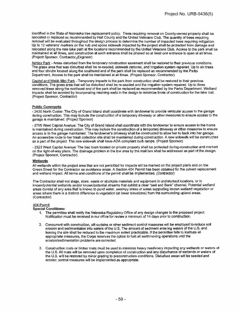
Project No. URB-5436(5)
- 59 -

Project No. URB-5436(5)
- 60 -

Project No. URB-5436(5)
- 61 -

Project No. URB-5436(5)
- 62 -

Project No. URB-5436(5)
- 63 -
WETLANDS 404 PERMIT

Project No. URB-5436(5)
- 64 -

Project No. URB-5436(5)
- 65 -

Project No. URB-5436(5)
- 66 -

Project No. URB-5436(5)
- 67 -

Project No. URB-5436(5)
- 68 -

Project No. URB-5436(5)
- 69 -
Project No. URB-5436(5)
- 70 -

Project No. URB-5436(5)
- 71 -

Project No. URB-5436(5)
- 72 -
Project No. URB-5436(5)
- 73 -

Project No. URB-5436(5)
- 74 -

Project No. URB-5436(5)
- 75 -

Project No. URB-5436(5)
- 76 -
FLOODPLAIN PERMIT
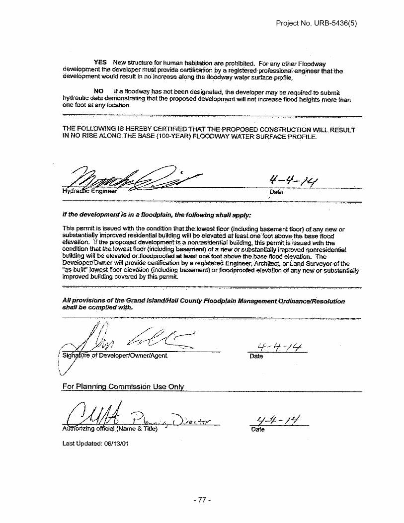
Project No. URB-5436(5)
- 77 -

Project No. URB-5436(5)
- 78 -
NOTICE TO BIDDERS (Storm Water Pollution Prevention Plan)
(A-20-0307)
The Contractor shall understand the terms and conditions of the general National Pollutant Discharge Elimination System (NPDES) permit that authorizes the storm water discharges associated with industrial activity from the construction site. For reference, the general permit is posted on the Department's website. Additionally, the Contractor, as evidenced by their signature on this proposal, agrees and understands that, if awarded the contract on this project, he/she:
1) becomes a co-permittee, along with the owner(s), to the Nebraska Department of Environmental Quality NPDES General Permit for Storm Water Discharges from construction sites on this project;
2) is legally bound to comply with the Clean Water Act to ensure compliance
with the terms and conditions of the storm water pollution prevention plan developed under the NPDES permit and the terms of the NPDES permit; and
3) will hold the owners harmless for damages or fines arising as a result of
noncompliance with the terms of the storm water permits and authorizations associated with the work on this project.
SPECIAL PROSECUTION AND PROGRESS (Migratory Birds)
(A-42-1112) The Department of Roads will, to the extent practicable, schedule the letting of projects such that clearing and grubbing can occur outside of the primary nesting season in Nebraska which has been determined to generally occur between April 1 and September 1. Work on structures, such as but not limited to bridges and culverts, should occur outside the primary swallow nesting season, April 15 to September 30, unless approved methods of avoiding nesting have been taken on the bridge and/or culvert structures. The nesting dates above are a guide only, nesting can occur outside of those dates. Work outside of those dates is not exempt from compliance with the Migratory Bird Treaty Act. The Contractor shall, to the extent possible, schedule work on structures, such as but not limited to bridges and culverts, and clearing and grubbing activities to occur outside the primary nesting season in Nebraska. However, if circumstances dictate that project construction or demolition must be done when nesting migratory birds may be present, a survey of the number of active nests and species of birds shall be conducted by qualified personnel representing the Contractor, and assisted by the Project Manager (PM), NDOR Environmental Section staff, or the United States Department of Agriculture (USDA) Animal and Plant Health Inspection Service (APHIS) - Wildlife Services Office. If the survey finds that nests will be impacted by the proposed construction, the Contractor may be responsible for delays.

Project No. URB-5436(5)
- 79 -
The following guidance is provided for compliance with the Migratory Bird Treaty Act for construction of NDOR projects:
1. The Contractor shall submit a plan to the NDOR regarding how he intends to
accomplish bridge demolition or clearing and grubbing of the project to avoid conflict with nesting migratory birds.
2. The Contractor must submit a temporary erosion control plan tailored to fit the
plan for clearing and grubbing. 3. If construction operations result in unavoidable conflict with nesting migratory
bird's eggs or young, which will result in "taking" nests and their contents, the Contractor should notify the NDOR Project Manager (PM). The PM shall notify the Environmental Section of Planning and Project Development by telephone at 402-479-4766.
4. The NDOR Environmental Section will then determine if assistance in conducting
the survey will be provided by the NDOR Environmental Section (if available) or from the USDA APHIS - Wildlife Services Office and arrange for assistance with the survey of nest numbers, bird species, etc. Results of the survey shall be maintained by the NDOR until project completion.
5. If the nesting survey is required, and the project was awarded prior to the nesting
season, and the Contractor did not accomplish clearing/grubbing and/or work on bridge/culvert structures outside the nesting season, the Contractor will reimburse the Department of Roads for each survey required at $1,000 per survey. If the project was awarded during the nesting season, and construction activities are such that clearing/grubbing and/or work on bridge/culvert structures must be accomplished prior to any other activity on the project, then there will be no charge assessed for the initial survey. The Contractor is responsible for removing all trees surveyed, that do not contain active nests, and for taking appropriate measures on bridge/culvert structures, within 3 days of the survey. Reimbursement for additional surveys may be charged if the Contractor fails to remove the trees within 3 days of the survey, and requires an additional survey. Survey reimbursement will be determined on a project specific basis, considering the project timeline and associated activities.
6. If an active nest is found during the survey, the Contractor should do everything
possible to restructure his activities and leave the nest undisturbed until the young fledge. Fledging could occur within a week, or up to a month, after the survey depending on the species of bird and whether the nest contained eggs or young. Also depending on the species of bird and their sensitivity to disturbance, a buffer of up to 30 feet surrounding the tree with the active nest could be required.
7. If construction cannot be rescheduled to allow the birds to fledge, and it is
determined as an unavoidable "take" circumstance, the Contractor shall stop all work within 30 feet of the active nest and coordinate with the Construction Project Manager to determine how to proceed. The Construction Project Manager will then coordinate with the NDOR Environmental Section and they will facilitate coordination with the US Fish and Wildlife Service and the Federal
Project No. URB-5436(5)
- 80 -
Highway Administration (for projects using Federal-aid) to determine the appropriate way to address the active nest. No work shall occur within 30 feet of the active nest until US Fish and Wildlife Service coordination is complete and the requirements of the Migratory Bird Treaty Act are satisfied.
8. It is the Contractor’s responsibility to schedule his work to accommodate the
process of conducting a survey(s) and submitting the necessary documentation if avoidance is not practicable. The Contractor shall be responsible for using any legal and practical method to prevent the nesting of birds in order to prevent the need for any survey and prevent the need for additional surveys. It is understood and agreed that the Contractor has considered in the bid all of the pertinent requirements concerning migratory birds (including endangered species) and that no additional compensation, other than time extensions if warranted, will be allowed for any delays or inconvenience resulting in these requirements.
STORM WATER DISCHARGES
(A-43-0408)
In compliance with the Federal Water Pollution Control Act, authorization to discharge storm water on this project has been granted under National Pollutant Discharge Elimination System (NPDES) General NPDES Permit Number NER110000 for Storm Water Discharges from Construction Sites to Waters of the State of Nebraska. This permit became effective on January 1, 2008. Contractors are advised that, under the Construction Storm Water General Permit, plant sites, camp sites, storage sites, and borrow or waste sites not shown on the plans may be subject to separate NPDES permit authorization requirements for stormwater discharges from those locations. Contractors shall be responsible for verifying the need for NPDES permit coverage with the Nebraska Department of Environmental Quality (NDEQ). When required for these locations, the filing of a "Notice of lntent" shall be made by the Contractor directly to the NDEQ. Additionally, asphalt (SIC Code 2951) or concrete (SIC Code 3273) batch plants that are owned by a private contractor and are operated on a contract-for-service basis to perform work for the Contractor completing the project may be subject to NPDES General Permit Number NER000000 for Industrial Storm Water Discharges. While the plant may be required for completion of the project, it is not under the control of the Department (or other project owner); and the filing of a "Notice of Intent" shall be made by the Contractor directly to the NDEQ. The NDEQ may be contacted at 402-471-4220 for additional information.
REQUIRED SUBCONTRACTOR/SUPPLIER QUOTATIONS LIST (A-43-0307)
All bidders must provide to the NDOR the identity of all firms who provided quotations on all projects, including both DBEs and non-DBEs. This information must be on a form provided by the NDOR Contracts Office. If no quotations were received, the bidder must indicate this in the space provided.
Each bidder will be required to submit one list per letting to cover all projects bid.

Project No. URB-5436(5)
- 81 -
PROPOSAL GUARANTY BID BOND (A-43-0307)
Paragraphs 1.a. and 1.b. of Subsection 102.15 in the Standard Specifications are void and superseded by the following: a. OPTION 1 - (Project Specific Paper Bid Bond). The Bid Bond shall be executed
on an original Department Bid Bond Form, which may be obtained from the Department. The original Bid Bond shall be delivered to the Department with the bid. A reproduction or a copy of the original form will not be accepted and will cause the bid not to be opened and read.
b. OPTION 2 - (Annual Bid Bond). The Department at its discretion may allow a
bidder to place an "Annual Bid Bond" on file with the Department. This bond would cover all projects the bidder bids for a 12-month period shown in the bond. The bidder must indicate in the bid submittal to the Department that their "Annual Bid Bond" applies to the submitted bid. The original Annual Bid Bond shall be executed on the Department of Roads Bid Bond Form, which may be obtained from the Department. A reproduction or a copy of the original form will not be accepted.
WORKER VISIBILITY (A-43-0507)
Pursuant to Part 634, Title 23, Code of Federal Regulations, the following modified rule is being implemented: Effective on January 1, 2008, all workers within the right-of-way who are exposed either
to traffic (vehicles using the highway for purposes of travel) or to construction equipment within the work area shall wear high-visibility safety apparel.
High-visibility safety apparel is defined to mean personal protective safety clothing that:
1 - is intended to provide conspicuity during both daytime and nighttime usage, and
2 - meets the Performance Class 2 or Class 3 requirements of the ANSI/ISEA 107-2004 publication titled "American National Standards for High-Visibility Safety Apparel and Headwear."
VALUE ENGINEERING PROPOSALS (VEP) (A-43-0807)
Subsection 104.03 in the Standard Specifications is amended to include the following:
14. A VEP will not be accepted if the proposal is prepared by an Engineer or the Engineering Firm who designed the contract plans.

Project No. URB-5436(5)
- 82 -
LEGAL RELATIONS AND RESPONSIBILITY TO THE PUBLIC
(A-43-0210) Paragraph 4.a. of Subsection 107.01 in the Standard Specifications is void and superseded by the following:
4. a. Whenever the Contractor violates any governing Federal, State or Local environmental quality regulation and/or is in noncompliance with any environmental commitment, the violating activity must cease immediately until the appropriate remedy can be determined by: the Engineer, the NDOR Environmental Section, the Federal Highway Administration (for projects utilizing Federal-aid) and other agencies, as deemed appropriate. The Engineer, with assistance from the NDOR Environmental Section and the FHWA, will provide a written order confirming the appropriate corrective action to the Contractor. Work can resume to normal conditions once the Engineer determines that the violation or non-compliance has been addressed in accordance with the order for corrective action.
Subsection 107.01 in the Standard Specifications is amended to include the following two paragraphs:
5. Should the Contractor encounter any previously unidentified hazardous materials, the Engineer shall be promptly notified. The Contractor shall suspend operations in the area involved until such time that arrangements are made for their proper treatment or removal.
6. The Contractor shall prevent the transfer of invasive plant and animal species.
The Contractor shall wash equipment at the Contractor's storage facility prior to entering the construction site. The Contractor shall inspect all construction equipment and remove all attached vegetation and animals prior to leaving the construction site.
SPECIAL PROSECUTION AND PROGRESS (Federal Immigration Verification System)
(A-43-1209) The Contractor shall register with and use a Federal Immigration Verification System to determine the work eligibility status of newly hired employees physically performing services within the State of Nebraska. The Prime Contractor shall contractually require every subcontractor to register with and use a Federal Immigration Verification System to determine the work eligibility status of newly hired employees physically performing services within the State of Nebraska. The Federal Immigration Verification System shall be an electronic verification of the work authorization program of the Illegal Immigration Reform and Immigration Responsibility Act of 1996, 8 U.S.C. 1324a, known as the E-Verify Program. The Contractor may use an equivalent Federal program designated by the United States Department of Homeland Security or other

Project No. URB-5436(5)
- 83 -
Federal agency authorized to verify the work eligibility status of a newly hired employee. The equivalent program shall comply with the Immigration Reform and Control Act of 1986. The Prime Contractor shall furnish a letter to the NDOR Construction Division in Lincoln on company letterhead and signed by an officer of the company stating that documentation is on file certifying that the Contractor and all subcontractors have registered with and used a Federal Immigration Verification System. The Contractor shall maintain all records of registration and use for a period of three years and make records available upon request. The Contractor shall contractually require subcontractors to maintain all records for a period of three years and make records available upon request. Payment will not be made to the Contractor for using the Federal Immigration Verification System or the maintenance of the records. This work shall be subsidiary to the work being performed. The Contractor’s Certification shall become part of the final records of the Contract. The Department considers this document to have direct bearing to the beginning interest date and may affect the amount of interest earned.
CONTRACT TIME ALLOWANCE (A-43-0911)
Paragraph 5. of Subsection 108.02 of the Standard Specifications is void and superseded by the following: 5. Each week, the Engineer shall post on the Department’s website a report of
working days or calendar days charged. The Contractor then has 14 days from the day the Engineer’s report is posted to provide a written explanation of why he/she does not concur with the working days or calendar days as assessed.
Paragraph 6.b. of Subsection 108.02 of the Standard Specifications is amended to include the following: (4) If the time allowance for the contract has been established on a calendar day
basis, the Contractor is expected to schedule the work and assign whatever resources are necessary to complete the work in the time allowance provided regardless of the weather. Accordingly, regardless of anything to the contrary contained in these Specifications, the Department will not consider delays caused by inclement or unseasonable weather as justification for an extension of the contract time allowance unless:
i. the weather phenomena alleged to have contributed to or caused
the delay is of such magnitude that it results in the Governor issuing a Disaster Declaration, and
ii. the weather phenomena alleged to have contributed to or caused the delay can clearly be shown to have directly impacted the work on the critical path identified on the Contractor’s schedule.

Project No. URB-5436(5)
- 84 -
Paragraphs 10.b. and 10.c. of Subsection 108.02 of the Standard Specifications are void and superseded by the following: b. (1) If the extra work is not in the original contract, time extensions will be
granted by determining the actual time necessary to accomplish the extra work.
(2) If the extra work is the result of the addition of additional quantities of
existing contract items, time extensions will be granted by either: (i) determining the actual time necessary to accomplish the extra
work; or (ii) determining the additional time to be granted by comparing the
value of the additional quantities of work to the total amount of the original contract when measurement of the actual additional time is not possible or practical.
(3) In either case, only the time necessary to perform the extra work of the
additional quantities of existing contract items when the extra work or the additional quantities of existing contract items are deemed to be the current controlling operation will be granted as a time extension.
c. Increases in quantities of work associated with traffic control items measured by
the day will not be considered for extending the contract time allowance. Overruns of traffic control items that are measured by methods other than time may be considered for extending the contract time allowance, but they must be deemed to be a controlling operation when the overrun of quantities occurs.
PARTIAL PAYMENT (A-43-1110)
Paragraph 2. of Subsection 109.07 of the Standard Specifications is void and superseded by the following: 2. When the value of the work completed during a semi-monthly period exceeds
$10,000, the Contractor will receive semi-monthly progress estimates from which the Department shall make such retentions as may be allowed by the contract, provided that the nature and quality of the completed work are satisfactory and provided further that the progress of the work conforms to the requirements of Subsection 108.07.
Paragraph 3.b. of Subsection 109.07 of the Standard Specifications is void and superseded by the following: b. Under normal circumstances, the Department shall not retain any earnings on a
progress estimate. However, the Department reserves the right to retain such amounts as are necessary for material deficiencies, anticipated liquidated damages, unpaid borrow, and for other reasons to protect the Department’s interests.

Project No. URB-5436(5)
- 85 -
PARTIAL PAYMENT (A-43-0611)
Paragraph 4. of Subsection 109.07 of the Standard Specifications is void and superseded by the following: 4. a. (1) Upon presentation by the Contractor of receipted bills, billing invoices, or
such other documentation sufficient to satisfy the Engineer and verify the Contractor’s or subcontractor’s actual costs for the materials, payments may also be allowed for acceptable nonperishable materials purchased expressly to be incorporated into the work and delivered in the vicinity of the project or stored in acceptable storage places within Nebraska.
(2) Materials not delivered and stored in the immediate vicinity of or on the
actual project site must be clearly marked to identify the project on which they are to be used, must be segregated from similar materials at the storage site, and cannot be included in a supplier’s inventory of material available for sale for other purposes.
(3) All items eligible for partial payment as stored materials must be available
for verification, sampling, and measurement. b. The amount to be included in the payment will be determined by the Engineer,
but in no case shall it exceed 100 percent of the value of the materials documented. This value may not exceed the appropriate portion of the value of the contract item or items in which such materials are to be incorporated, nor shall the quantity in any case exceed the total estimated quantity required to complete the project.
c. Payment will not be approved when the documented value of such materials
amounts to less than $1,000.00, when the progress of the work is not in accordance with the requirements set forth in Subsection 108.07, or when the material can reasonably be expected to be incorporated into the work and eligible for payment as completed work on a progress estimate within 15 days of being placed into storage.
d. Deductions at rates and in amounts which are equal to the payments will be
made from estimates as the materials are incorporated into the work. e. Payment for the materials shall not in itself constitute acceptance, and any
materials which do not conform to the specifications shall be rejected in accordance with Subsection 106.05.
f. The Contractor shall be responsible for all damages and material losses until the
material is incorporated into the work and the work is accepted.

Project No. URB-5436(5)
- 86 -
g. Partial payment will not include payment for fuels, supplies, form lumber, falsework, other materials, or temporary structures of any kind which will not become an integral part of the finished construction.
h. No partial payments will be made on living or perishable plant materials until
planted.
BUY AMERICA (A-43-0212)
Subsection 106.07 in the Standard Specifications is void and superseded by the following: 106.07 -- Buy America 1. The Buy America rule requires that steel or iron materials be produced
domestically, and only those products which are brought to the construction site and permanently incorporated into the completed project are covered. Construction materials, forms, etc., which remain in place at the Contractor's convenience, but are not required by the contract, are not covered.
2. To further define the coverage, a domestic product is a manufactured steel
construction material that was produced in one of the 50 States, the District of Columbia, Puerto Rico, or in the territories and possessions of the United States.
3. All manufacturing processes to produce steel or iron materials (i.e., smelting, and
any subsequent process which alters the steel or iron material's physical form or shape, or changes its chemical composition) must occur within one of the 50 States, the District of Columbia, Puerto Rico, or in the territories and possessions of the United States, to be considered of domestic origin. This includes processes such as casting, rolling, extruding, machining, bending, grinding, drilling, and coating. Coating includes epoxy coating, galvanizing, painting, and any other coating that protects or enhances the value of the material. The manufacturer shall include a statement on the material test report or certification that all material described above except the coating material is a domestic product.
4. Raw materials used in the steel or iron materials may be imported. All
manufacturing processes to produce steel or iron materials must occur domestically. Raw materials are materials such as iron ore, limestone, waste products, etc., which are used in the manufacturing process to produce the steel products. Waste products would include scrap; i.e., steel no longer useful in its present form from old automobiles, machinery, pipe, railroad tracks and the like. Also, steel trimmings from mills or product manufacturing are considered waste. Extracting, crushing, and handling the raw materials which is customary to prepare them for transporting are exempt from Buy America. The use of pig iron and processed, pelletized, and reduced iron ore manufactured outside of the United States may be used in the domestic manufacturing process for steel and/or iron materials.

Project No. URB-5436(5)
- 87 -
5. Notwithstanding this requirement, a minimum of foreign steel or iron materials will be permitted if its value is less than one-tenth of one percent of the total contract cost or $2,500, whichever is greater.
6. Upon completion of all work utilizing steel or iron products, the Prime Contractor
shall furnish a letter to the State on company letterhead and signed by an officer of the company stating that documentation is on file certifying that all steel or iron materials brought to the construction site and permanently incorporated into the work complied in all respects with the Buy America requirements.
BORROW, WASTE, STOCKPILE, AND PLANT SITE APPROVAL (A-43-0512)
Subsection 107.02 in the Standard Specifications is amended to include the following: 4. Site Approval: a. When borrow is obtained from a borrow site or waste excavation is placed
at sites which are not shown in the contract, or the Contractor plans to use a plant or stockpile site which is not shown in the contract, the Contractor shall be solely responsible for obtaining all necessary site approvals. The Department will provide the procedures necessary to obtain approvals from the U.S. Army Corps of Engineers, U.S. Fish and Wildlife Service, Nebraska State Historical Society, Nebraska Game and Parks Commission, and Nebraska Department of Natural Resources on the NDOR website. The Contractor shall also be responsible for obtaining a Discharge Number from the Nebraska Department of Environmental Quality (NDEQ) that allows work under the current Construction Stormwater Permit. The Contractor shall also be responsible for obtaining any and all other permits required by local governments.
b. It is anticipated that it may require 60 calendar days or more for the
Contractor to obtain the necessary approvals. The Contractor will not be allowed to begin work at borrow or waste sites until the necessary approvals are obtained. No extension of completion time will be granted due to any delays in securing approval of a borrow or disposal site unless a review of the time frames concludes that there were conditions beyond the Contractor’s control.
Paragraph 7. of Subsection 205.02 in the Standard Specifications is void and superseded by the following: 7. Borrow and Waste Site Approval: a. Borrow and waste site approvals shall be in accordance with
Section 107.02. b. Material shall not be removed from borrow sites until preliminary cross
sections and representative soil samples have been taken by the

Project No. URB-5436(5)
- 88 -
Engineer. The Contractor shall notify the Engineer a sufficient time in advance of the opening of any borrow site so that cross sections may be taken.
c. Material shall be removed in a manner that will allow accurate final cross
sections to be taken for determining the quantity of excavation. The surfaces of the borrow sites shall be bladed and shaped to drain as shown in the contract or as directed by the Engineer.
SPECIAL PROSECUTION AND PROGRESS (Subletting or Assigning of Contract)
(A-43-0414) Subsection 108.01 in the Standard Specifications is void and superseded by the following: 108.01 – Subletting or Assigning of Contract 1. a. (1) The Contractor will not be allowed to sublet, assign, sell, transfer, or
otherwise dispose of any portion of the contract or any right, title, or interest therein; or to either legally or equitably assign any of the money payable under the contract or the claims without the prior written consent of the Engineer.
(2) With the Engineer’s consent, the Contractor may sublet up to 70 percent
of the work.
(3) Any items designated in the contract as “specialty items” may be performed by subcontract.
(4) The cost of any subcontracted “specialty items” may be deducted from
the total contract cost before computing the percentage of work required to be performed by the Contractor.
(5) Subcontracts, or transfer of contract, will not release the Contractor of any
liability under the contract and bonds. b. Certain items of work may be performed without a subcontract. A list of items not
requiring a subcontract is available from the Engineer. 2. The performance of any work by a subcontractor before the date of authorization
by the Department shall subject both the Contractor and subcontractor to the imposition of appropriate sanctions by the Department.
3. a. The Contractor’s request to sublet work shall be made electronically to the NDR
Construction Engineer using project management software identified by the Department. A signed subcontract agreement shall be on file in the Contractor’s office when the request is made. The subcontract agreement must provide that the subcontracted work will be completed according to the terms of the contract.

Project No. URB-5436(5)
- 89 -
The required and Special Provisions contained in the proposal shall be physically included in any subcontract.
b. On all Federal-aid projects, a scanned copy (.pdf format) of the signed
subcontract agreement shall be included with the subcontracting request. (Federal-aid projects can be identified by inclusion in the Proposal of Form FHWA-1273 (REQUIRED CONTRACT PROVISIONS FEDERAL-AID CONSTRUCTION CONTRACTS).
c. Scanned copies (.pdf format) of all executed subcontracts, written agreements,
and/or lease agreements used to meet DBE goals shall be submitted to the NDR Construction Engineer with the subcontracting request. These copies must show labor cost, material prices, overhead and profit.
4. a. Second tier subcontracts will be allowed. b. If a DBE firm subcontracts work to another firm, only work subcontracted to
another DBE firm can be counted toward meeting a DBE goal. c. All requests for second tier subcontracting shall be submitted to and approved by
the Prime Contractor before they are forwarded to the NDR Construction Engineer for approval.
5. All subcontract documents relating to the contract shall be maintained during the
course of the work and preserved for a period of three years thereafter. These documents shall be available for inspection by authorized representatives of State and Federal agencies. Scanned copies (.pdf format) of the signed subcontract agreements not specifically identified elsewhere in this Subsection shall be furnished to the Department upon request.
6. The Contractor may discuss a proposed subcontract with the Engineer before
entering into a signed subcontract agreement, but final approval will not be granted until a formal request and proper certification has been received by the Department.
7. On projects requiring submittal of certified payrolls, all subcontractor payrolls
shall be checked by the Contractor before submittal to the Engineer. 8. a. The Prime Contractor, and subcontractors when subletting work to lower tier
subcontractors, shall include language which can be identified as a “Prompt Payment Clause” as a part of every subcontract for work and materials.
b. (1) The language constituting the “Prompt Payment Clause” will require
payment to all first tier subcontractors for all labor and materials --- for work completed to date --- within 20 calendar days of receipt of progress payments from the Department for said work. Similar language in a contract between a subcontractor and a lower-tier subcontractor will require payment to the lower tier subcontractor for all labor and materials --- for work completed to date --- within 10 calendar days of receipt of progress payments from the prime Contractor for said work.

Project No. URB-5436(5)
- 90 -
(2) The language constituting the “Prompt Payment Clause” will also stipulate the return of retainage within 30 calendar days after the satisfactory completion of the work by the subcontractor as evidenced by inclusion of the work on a progress payment.
(3) Additionally, the language constituting the “Prompt Payment Clause” may
stipulate the subcontractor’s obligation to return to the Contractor or subcontractor, as the case may be, any overpayments which result from adjustments to measured and recorded quantities as part of the preparation of subsequent progress payments or the final records. Overpayments shall be returned to the Prime Contractor or subcontractor, as the case may be, within 20 calendar days of receiving notice of the adjusted quantities and the amount of the overpayment.
c. The Prime Contractor of subcontractors, as the case may be, may withhold
payment only for just cause and shall not withhold, delay, or postpone payment without first receiving written approval from the Department.
d. (1) The failure by the Prime Contractor to abide by the agreements identified
in the “Prompt Payment Clause” without just cause, including the timely return of retainage, is a material breach of this contract which may result in the Department withholding the amount of payment from the prime Contractor that should have been paid to the subcontractor, termination of this contract, or other such remedy as the Department deems necessary.
(2) Additionally, the failure of any subcontractor to abide by the agreements
identified in the “Prompt Payment Clause” without just cause, including the timely return of retainage to lower tier subcontractors, or by failing to return overpayments in a timely manner when the language permitted in Paragraph 8.b.(3) above is included in the subcontract may result in the Department withholding subcontract approval for other work until the overpayments have been returned.
9. a. (1) For Davis Bacon (DBRA)-covered projects and Non-DBRA-covered
projects, a Contractor or subcontractor may wish to use another individual owner-operator or trucking company to supplement his or her hauling fleet. (The Department will not recognize multiple individuals claiming to be collectively identified as a single “owner operator.)
(2) This supplemental individual or company must either become a
subcontractor (first tier or lower tier, as the case may be) or be otherwise documented by the utilizing Contractor or subcontractor by entering into a lease agreement for the trucks and showing the driver (or drivers) from the supplemental company on the Prime Contractor’s or subcontractor’s payrolls in the manner described below.
(3) Payrolls will only be accepted from the Prime Contractor or approved
subcontractors.
b. (1) If the decision is made to subcontract the hauling, the Prime Contractor must first notify the NDOR Construction Office to request subcontract

Project No. URB-5436(5)
- 91 -
approval. As part of the subcontract approval process --- at any tier --- the proper certificates of insurance must be provided before approval will be granted.
(2) Additionally, on DBRA-covered projects, the Prime Contractor must submit payrolls for all subcontractors --- at any tier.
c. (1) Owner/Operators of trucks hired by a Contractor or subcontractor to
supplement his or her hauling fleet are not subject to Davis Bacon wage requirements. However, they must still be shown on a payroll prepared by the Contractor or subcontractor for whom they are working with the notation “owner/operator.”
(2) Any other employees of the “owner/operator” must appear on the certified
payroll in complete detail and must be compensated according to the wage rates established for the project.
d. In the event a Prime Contractor or subcontractor elects to not subcontract the
supplemental driver or drivers but instead chooses to “carry the workers/truckers on their payroll,” the following requirements must be met:
(1) The Prime Contractor’s or subcontractor’s certified payroll must contain
the names of all workers/truck drivers, and the payroll should identify their supervisors (including “owner-operators”).
(2) Pay checks for the workers/truckers in question must be drawn against
the Prime Contractor’s or subcontractor’s payroll or other account. (3) Owner/Operators need only be identified as such on the payroll.
Additional drivers, if any, from the “owner-operator’s” company must appear on a payroll in complete detail and be compensated according to the wage rates established for the project.
(4) The Prime Contractor or subcontractor must enter into a lease agreement
for the trucks driven by such drivers, and the lease agreement must show that the compensation for the leased equipment is on a time basis and not based on the amount of work accomplished. The lease agreements must be available for inspection by NDOR personnel.
(5) Any supplemental truckers employed under this arrangement must still
carry the minimum automobile liability coverage specified in the contract. It shall be the duty of the Prime Contractor to ensure that the supplemental truckers have such coverage in effect. Evidence of proper insurance must be presented for verification on demand.
SHOP PLANS AND ELECTRONIC SHOP DRAWINGS (A-43-0514)
Paragraph 5. of Subsection 105.02 in the Standard Specifications is amended to provide that the Contractor may furnish shop plans on half-size plan sheets [11x17 inches (297x420mm)], provided all information is legible.
Project No. URB-5436(5)
- 92 -
Subsection 105.02 of the Standard Specifications is amended to include the following: 8. a. (1) The Contractor may provide electronic working drawings in a Portable
Document Format (PDF). The PDFs shall be sized to print on an 11 x 17 inch sheet of paper and have a minimum resolution of 300 dpi. Each sheet of the shop drawings shall have a space provided for an electronic stamp that measures 2.5 inches x 3.5 inches when printed.
(2) Electronic working drawing files shall be named with the following file
naming format:
Control Number_Brief Description_Date.pdf For example: 12345_FloorDrains_12May2013.pdf (3) The project number, control number, and project location as it appears on
the plans shall be shown on each sheet of the shop drawings or on the front sheet only for catalog cuts, design calculations and product data sheets. Structure numbers shall be included, if applicable.
b. No electronic working drawings shall be submitted to the Engineer unless they
have been checked by the Contractor. The electronic submittal shall be accompanied by a Contractor’s letter of approval in a PDF format. The letter of approval shall clearly indicate that the Contractor is responsible for any errors on the working drawings.
c. (1) Electronic submittals shall be submitted by email to the following address:
[email protected] (2) Attachments shall be limited to 25 MB of data per email. Larger files shall
be separated and sent in multiple emails. (3) Electronic working drawings will only be accepted from the Prime
Contractor.
LIABILITY INSURANCE (A-54-0414)
Subsection 107.13 in the Standard Specifications is void and superseded by the following: 107.13 – Liability Insurance
Prior to execution of the contract, the Contractor shall obtain insurance coverage to fully protect it from loss associated with the work, and have at a minimum the insurance described below:
1. General Liability: Limits of at least:
$ 1,000,000 per Occurrence $ 2,000,000 General Aggregate

Project No. URB-5436(5)
- 93 -
$ 2,000,000 Completed Operations Aggregate $ 1,000,000 Personal and Advertising Injury
a. Contractor shall be responsible for the payment of any deductibles.
b. Coverage shall be provided by a standard form Commercial General Liability Policy (CG0001 or equivalent) covering bodily injury, property damage including loss of use, and personal injury.
c. The General Aggregate shall apply on a Per Project Basis.
d. The Owner and the State of Nebraska, Department of Roads, shall be named as Additional Insureds on a primary and non-contributory basis including completed operations for three (3) years after final acceptance and payment.
e. Contractor agrees to waive its rights of recovery against the Owner and the State of Nebraska, Department of Roads. Waiver of Subrogation in favor of the Owner and the State of Nebraska, Department of Roads shall be added to the policy.
f. Contractual liability coverage shall be on a broad form basis and shall not be amended by any limiting endorsements.
g. If work is being performed near a railroad track, the 50' railroad right of way exclusion must be deleted.
h. Products and completed operations coverage in the amount provided above shall be maintained for the duration of the work, and shall be further maintained for a minimum period of three years after final acceptance and payment.
i. Coverage shall be included for demolition of any building or structure, collapse, explosion, blasting, excavation and damage to property below surface of ground (XCU coverage).
j. Policy shall not contain a total or absolute pollution exclusion. Coverage shall be provided for pollution exposures arising from products and completed operations as per standard CG0001 Pollution Exclusion or equivalent. If the standard pollution exclusion as provided by CG0001 has been amended, coverage must be substituted with a separate Pollution Liability policy of $1.0 million per occurrence and $2.0 million aggregate. If coverage is provided by a “claims made” form, coverage will be maintained for three years after project completion. Any applicable deductible is the responsibility of the Contractor.
2. Automobile Liability: Limits of at least: $ 1,000,000 CSL per Accident
a. Coverage shall apply to all Owned, Hired, and Non-Owned Autos.
b. If work is being performed near a railroad track, the 50-foot railroad right-of-way exclusion must be deleted.
c. Contractor agrees to waive its rights of recovery against the Owner and the State of Nebraska, Department of Roads. Waiver of Subrogation in

Project No. URB-5436(5)
- 94 -
favor of the Owner and the State of Nebraska, Department of Roads, shall be added to the policy.
3. Workers’ Compensation: Limit: Statutory coverage for the State where the project is located.
Employer’s Liability limits: $500,000 Each Accident $500,000 Disease – Per Person $500,000 Disease – Policy Limit
a. Contractor agrees to waive its rights of recovery against the Owner and the State of Nebraska, Department of Roads. Waiver of Subrogation in favor of the Owner and the State of Nebraska, Department of Roads shall be added to the policy.
b. Where applicable, the Longshore and Harborworkers Compensation Act endorsement shall be attached to the policy.
4. Umbrella/Excess: Limits of at least: $1,000,000 per Occurrence a. Policy shall provide liability coverage in excess of the specified Employers
Liability, Commercial General Liability and Automobile Liability.
b. The Owner and the State of Nebraska, Department of Roads, shall be “Additional Insureds.”
c. Contractor agrees to waive its rights of recovery against the Owner and the State of Nebraska, Department of Roads. Waiver of subrogation in favor of the Owner and the State of Nebraska, Department of Roads shall be provided.
5. Pollution Liability:
a. When “hazardous wastes” or contaminated or polluted materials must be handled and/or moved, the Contractor shall obtain Pollution Liability Coverage with minimum limits of $1,000,000 per occurrence and $2,000,000 aggregate.
b. If, during the course of construction, hazardous wastes, contaminated or polluted material are discovered on the project, the Contractor shall immediately cease any operation that may disturb these materials, and shall immediately notify the Engineer of all facts related to the discovery of these materials.
c. Unforeseen work related to the discovery of hazardous, contaminated or polluted materials on the project, and the extra cost, if any, of pollution liability coverage will be handled as “extra work.”
6. Additional Requirements:
a. The Contractor shall provide and carry any additional insurance required by the Special Provisions.
b. Except as otherwise provided herein, all insurance shall be kept in full force and effect until after the State releases the Contractor from all obligations under the contract.
Project No. URB-5436(5)
- 95 -
c. (1) If any of the work is sublet, equivalent insurance shall be provided by or on behalf of the subcontractor or subcontractors (at any tier) to cover all operations.
(2) Approved trucking subcontractors (at any tier) who are being utilized only for the purpose of hauling materials shall be exempt from the requirements of Paragraphs 1, 4, and 5.
(3) (i) When a Contractor or subcontractor chooses to employ a trucker by carrying the driver on his or her payroll and entering into a lease agreement for the truck, the owner-operator of the truck shall be required to comply with the Automobile Liability provisions of Paragraph 2.
(ii) Furthermore, it shall be the duty of the Prime Contractor to ensure that the owner-operator of the truck has such insurance in effect. The Prime Contractor shall maintain evidence that any truckers so utilized (at any tier) are insured to the minimum limits specified and be able to furnish documentation of the same on demand.
(iii) Failure to ensure that insurance coverage exists and failure to maintain evidence thereof shall be considered a breach of the contract.
d. Any insurance policy shall be written by an insurance company with a Best’s Insurance Guide Rating of A – VII or better.
e. Prior to execution of the contract, Contractor shall provide Owner and the State of Nebraska, Department of Roads evidence of such insurance coverage in effect in the form of an Accord (or equivalent) certificate of insurance executed by a licensed representative of the participating insurer(s). Certificates of insurance shall show the Owner and Nebraska Department of Roads as the certificate holders.
f. For so long as insurance coverage is required under this agreement, the Contractor shall have a duty to notify the Owner and the State of Nebraska Department of Roads (State) when the Contractor knows, or has reason to believe, that any insurance coverage required under this agreement will lapse, or may be cancelled or terminated. The Contractor must forward any pertinent notice of cancellation or termination to both the Owner and to the State by mail (return receipt requested), hand-delivery, or facsimile transmission within 2 business days of receipt by Contractor of any such notice by an insurance carrier. Copies of notices received by the Contractor shall be sent to the Owner at the address listed for the Responsible Charge set out elsewhere in the Supplemental Provisions and to the State at the following address:
Nebraska Department of Roads Construction Division --- Insurance Section 1500 Highway 2, P.O. Box 94759 Lincoln, NE 68509-4759
Facsimile No. 402-479-4854

Project No. URB-5436(5)
- 96 -
g. Failure of the owner or any other party to review, approve, and/or reject a certificate of insurance in whole or in part does not waive the requirements of this agreement.
h. The limits of coverage set forth in this document are suggested minimum limits of coverage. The suggested limits of coverage shall not be construed to be a limitation of the liability on the part of the Contractor or any of its subcontractors/tier subcontractors. The carrying of insurance described shall in no way be interpreted as relieving the Contractor, subcontractor, or tier subcontractors of any responsibility or liability under the contract.
i. If there is a discrepancy of coverage between this document and any other insurance specification for this project, the greater limit or coverage requirement shall prevail.
NOTICE TO BIDDERS (A-54-0210)
While the plans and specifications call for and make reference to the Department of Roads and its various Divisions to make decisions and test materials for acceptance, this project has been delegated under 23 CFR 635.105 to the Local Public Agency Owner, who shall administer the project. Therefore, any reference to the Department of Roads’ responsibility to: interpretation of the plans and specifications, inspection of the work, testing and acceptance of materials, approval of the work, and final acceptance of the project, shall be delegated to the Local Public Agency Owner and their representative.
LOCAL PUBLIC AGENCY RESPONSIBLE CHARGE Upon execution of the contract, the Contractor is to direct all project related communication to the Responsible Charge (RC) designated by the project owner (Local Public Agency). Responsible Charge:
Mr. Terry Brown City of Grand Island Public Works Dept. 100 East First Grand Island, NE 68802 [email protected] 308-685-5444
Project No. URB-5436(5)
- 97 -
SPECIAL PROSECUTION AND PROGRESS (Project Liquidated Damages)
(A-54–0212) For this project, the formula used to determine Project Liquidated Damages, as determined in Paragraph 2. of Subsection 108.08 in the Standard Specifications, is amended to read: LD = R X C T Where: LD = Liquidated damages per working day or calendar (rounded to the nearest
dollar). C = Original contract amount (includes all work completed and unfinished). T = Original number of calendar days or working days, whichever is specified
in the contract. R = 0.12 for LPA projects.
SPECIAL PROSECUTION AND PROGRESS (Construction Signs & Barricades)
(A-54–1112) With the exception of detour route signage and any non-standard signs not shown in the plans, the Contractor shall be responsible for furnishing, installing, maintaining and removing all construction signs and barricades, in accordance with the provisions of Section 422 in the Standard Specifications.
CONSTRUCTION DETAILS
FUEL COST ADJUSTMENT PAYMENT (B-1-0708)
Paragraph 16.a. of Subsection 205.05 in the Standard Specifications is amended to provide that the references to fuel cost fluctuation will be 5% instead of the 10% shown.
The fuel use factor, "F", shown in Paragraph 16.c. of Subsection 205.05 is void and superseded by the following:
F = English The fuel use factor for diesel fuel, in gallons per cubic yard. For the items of work "Excavation", "Excavation, Borrow", and "Excavation, Established Quantity", "F" shall be equal to 0.20. For the item of work "Earthwork Measured in Embankment", "F" shall be equal to 0.27.
Metric The fuel use factor for diesel fuel, in liters per cubic meter. For the items of work "Excavation", "Excavation, Borrow", and "Excavation, Established Quantity", "F" shall be equal to 0.99. For the item of work "Earthwork Measured in Embankment", "F" shall be equal to 1.32.
Project No. URB-5436(5)
- 98 -
Paragraph 16.d. of Subsection 205.05 is void and superseded by the following:
d. The allowable price differential, "D", for the current estimate will be computed according to the following formula:
When the current price, P, is greater than the base price, P(b). D = P - 1.05P(b), but not less than zero. When the current price, P, is less than the base price, P(b). D = P - 0.95P(b), but not greater than zero.
WATER (B-1-0307)
Paragraph 4.a. of Subsection 205.04 in the Standard Specifications is amended to include the following:
Payment shall be made at the established contract unit price.
EXCAVATION AND EMBANKMENT (B-1-0212)
Paragraph 6. of Subsection 205.02 in the Standard Specifications is void and superseded by the following:
6. Frozen Layers:
a. Thin Frozen Layer. A thin soil layer that freezes during the construction of an embankment may remain provided that the layer:
(i) had proper density and moisture prior to freezing, (ii) can be readily broke up by a single pass of a tamping
(sheepsfoot) roller or track mounted excavator, (iii) is thoroughly scarified into pieces having a single dimension of 3
inches or less, and a second dimension of ½ inch or less, and (iv) is not within 10 inches (measured vertically) of any thin frozen
layer that was previously scarified and left in place. b. Thick Frozen Layer. A soil layer that freezes during the construction of an
embankment, but does not meet the Thin Frozen Layer requirements:
(i) may remain in the embankment provided that the layer is thawed and has proper density and moisture after thawing, or
(ii) shall be completely removed from the embankment prior to placing any additional embankment material.
Project No. URB-5436(5)
- 99 -
TEMPORARY WATER POLLUTION CONTROL (B-3-1014)
Section 204 in the Standard Specifications is void.
CONSTRUCTION STORMWATER MANAGEMENT CONTROL (B-3-1014)
A. General
1. This Section defines some best management practices (BMPs) for erosion and sediment control measures and construction practices the Contractor shall use to prevent soil erosion and avoid water pollution.
2. a. The Department and the Contractor are co-permittes of the NPDES
Construction Storm Water General Permit.
b. The Contractor shall comply with all conditions required by the current NPDES Construction Storm Water General Permit.
3. The Contractor shall exercise every reasonable precaution throughout the life of
the contract to prevent silting of the waters of the state, the project site, and adjacent property. Construction of drainage facilities, as well as performance of other contract work which will contribute to the control of siltation, shall be carried out in conjunction with earthwork operations or as soon thereafter as is practicable.
4. a. The Contractor shall take sufficient precautions to prevent pollution of the
waters of the state, the project site, and adjacent property from construction debris, petroleum products, chemicals, or other harmful materials.
The Contractor shall conduct and schedule the operations to avoid
interference with any protected species. b. The Contractor shall comply with all applicable statutes relating to
pollution of the waters of the state and fish and game regulations.
5. All construction debris shall be disposed in a manner that it cannot enter any waterway. Excavation shall be deposited as to protect the waters of the state from siltation.
6. All erosion and sediment control measures shall be properly installed and
maintained by the Contractor until all permanent drainage facilities have been constructed, and all slopes are sufficiently vegetated to be an effective erosion deterrent; or until tentative acceptance of the work.
7. All erosion and sedimentation resulting from the Contractor's operations and the
weather conditions must be corrected by the Contractor.

Project No. URB-5436(5)
- 100 -
LIMITATION OF OPERATIONS (B-3-1014)
A. General
1. The maximum exposed surface area for the Contractor's operations in excavation, borrow, and embankment is 18 acres (72,800 m2) plus an equal area of clearing and grubbing/large tree removal. A written request for an increase in the maximum exposed surface area may be approved by the Engineer. This approval will be based on the soil, moisture, seasonal conditions, the Contractor’s operation, or other conditions.
2. The Engineer shall have the authority to reduce the maximum exposed surface
area when any of the following conditions warrant:
a. Soil and moisture conditions are such that erosion is probable.
b. Seasonal conditions may force extended delays.
c. Proximity to the waters of the state requires more stringent controls.
d. Equipment and personnel available on the job is not sufficient to properly maintain erosion and dust control measures.
e. Any other environmental condition in the area that may exist which would
be affected by erosion from the project. 3. Construction operations in rivers, streams, wetlands, and impoundments shall be
restricted to those areas specifically shown in the contract. Rivers, streams, wetlands, and impoundments shall be promptly cleared of all false work, piling, debris, or other obstructions placed therein or caused by the construction operations.
4. Fording and operation of construction equipment within streams and wetlands will not be
allowed, unless explicitly allowed in the contract. Streams are defined as any area between the high banks, regardless of the flow conditions.
CONSTRUCTION METHODS (B-3-1014)
A. General
1. The Contractor shall conduct all construction activities and install temporary erosion control measures, as necessary, to control sediment and avoid soil erosion during construction.
2. The Contractor shall incorporate all permanent erosion control features into the
project at the earliest practicable time.

Project No. URB-5436(5)
- 101 -
3. Construction stormwater management control measures for Contractor obtained
work areas located outside the right-of-way, such as borrow site operations, haul roads, plant sites, staging sites, waste sites, equipment storage sites, etc. are the sole responsibility of the Contractor. All construction stormwater management control measures for these areas are at the Contractor’s expense. The Contractor is responsible for securing all required permits for use of these sites.
4. The construction stormwater management procedures contained herein shall be
coordinated with any permanent erosion control measures specified elsewhere in the contract to the extent practical to assure economical, effective, and continuous erosion and sediment control throughout the construction period.
5. The Contractor shall be responsible to limit erosion and prevent siltation into the
waters of the state during the construction period, as well as during the times that work may be suspended.
6. a. All erosion and sediment control items shall be installed by personnel who
are knowledgeable in the principles and practice of various BMP installations.
b. The installation of all erosion and sediment control items shall be done
under the direct supervision of the Contractor’s employee who has successfully completed training provided by the Department and has been certified as an Erosion and Sediment Control Inspector (Inspector). The Contractor’s Inspector shall be present at each site during installation to direct and inspect all erosion and sediment control BMP installations.
i. The NDOR Erosion and Sediment Control Inspector Certification
is obtained by completing an Erosion and Sediment Control Inspector Training Course provided by the Nebraska Department of Roads and passing the examination that accompanies the training.
c. The Contractor shall notify the Engineer of all employees, who have been
certified as Inspectors, who will be on the project to direct and inspect all erosion and sediment control BMP installations.
d. No payment will be made for any erosion and sediment control item
unless a Contractor’s Inspector was present to directly supervise and inspect the work.
e. No payment will be made for any erosion and sediment control item that
is not properly installed. All erosion and sediment control items shall be installed as per the contract.
Project No. URB-5436(5)
- 102 -
ENVIRONMENTAL COMMITMENT DOCUMENT (B-3-1014)
A. Environmental Commitment Document 1. a. An Environmental Commitment Document will be created by the
Department to identify all project specific environmental commitments and will be included in the Contract.
b. The Department will provide information for the following, when
applicable: i. Storm Water Pollution Prevention Plan (SWPPP) ii. U.S. Army Corps of Engineers (USACE) Section 404 Permit iii. Nebraska Department of Environmental Quality 401 Water Quality
Certification iv. State Title 117 Waters (USACE Non-Jurisdictional) v. Floodplain Permit vi. Historic Clearance vii. Endangered Species Act Clearance viii. Nebraska Nongame and Endangered Species Conservation Act
Clearance ix. National Environmental Policy Act Compliance x. NPDES Construction Stormwater Permit (within Right-of-Way
limits, only) xi. Conservation Measures xii Migratory Bird Treaty Act xiii. Bald and Golden Eagle Protection Act Compliance xiv. Other pertinent issues c. The Contractor shall provide information for the following, when
applicable: i. Temporary Erosion Control Plan ii. Spill Prevention and Control Plan iii. Migratory Bird Treaty Act Compliance Plan iv. Name and telephone number of the Contractor’s representative
responsible for the Environmental Commitments v. Name and telephone number of the employees that are NDOR-
Certified Erosion and Sediment Control Inspectors vi. Critical Path Construction Schedule vii. Other items as defined elsewhere in the contract

Project No. URB-5436(5)
- 103 -
STORM WATER POLLUTION PREVENTION PLAN (SWPPP) (B-3-1014)
A. General 1. A SWPPP is required for projects that construction activities will cause a land
disturbance of one (1) acre or more. The Department will prepare the SWPPP for the areas within the Right-of-Way, temporary easements and permanent easements.
2. For projects not requiring a SWPPP, the Contractor shall comply with the
requirements of Environmental Commitment Document, Paragraph 1.b. of this Special Provision, as applicable.
3. Contractor obtained work areas, located on private property, are not included in
the NDOR Project SWPPP. B. Temporary Erosion Control Plan 1. The Contractor shall prepare and submit the Temporary Erosion Control Plan
prior to the start of any work. The Contractor shall not begin work until the Temporary Erosion Control Plan has been submitted to the Engineer and appropriate erosion control measures are in place. Payment for any work on the contract will be withheld if erosion control measures are not in place or properly maintained.
2. The Temporary Erosion Control Plan will be reviewed at project progress
meetings. All active Contractors shall have their Inspectors present and work in cooperation to determine any necessary changes. Necessary changes will be documented on the Temporary Erosion Control Plan by the Engineer.
3. Payment for preparing the Temporary Erosion Control Plan, inspections and
meeting reviews are subsidiary to items that direct payment is made. C. Spill Prevention and Control Plan 1. All project activities shall be addressed in the Spill Prevention and Control Plan.
The Contractor shall prepare and submit the plan to the Engineer and install all appropriate spill prevention and control measures prior to the start of any work.
2. The Spill Prevention and Control Plan shall clearly state measures to prevent,
contain, document and clean up a spill. It shall state measures for disposal of the contaminated material, disposal documentation and incident review to train personnel to prevent spills from reoccurring.
3. Spill Prevention and Control Plans are applicable to construction sites where
hazardous materials are stored, used and/or generated onsite. Hazardous materials include, but not limited to: hazardous wastes, pesticides, paints, cleaners, petroleum products, fertilizers, solvents and porta-potty wastes.
4. Direct payment will not be made for the Spill Prevention and Control Plan.

Project No. URB-5436(5)
- 104 -
D. Migratory Bird Treaty Act Compliance Plan 1. The Contractor shall not begin work until a Migratory Bird Treaty Act Compliance
Plan has been submitted to the Engineer and appropriate nesting migratory bird avoidance measures are in place.
2. a. The Contractor shall clearly state the necessary measures they intend to
use to avoid a “Take” of nesting migratory birds in the Migratory Bird Treaty Act Compliance Plan. Measures may include but are not limited to:
i. Clearing and grubbing prior to April 1st or after September 1st
ii. Tree removal prior to April 1st or after September 1st
iii. Clearing empty nests on structures prior to April 1st
iv. Maintaining clear structures until commencement and throughout the duration of work on structures
v. Netting structures to prevent nesting vi. Commitment to perform surveys according to protocol vii. Hire a biologist to survey areas to be disturbed prior to
commencement of work during the nesting season viii. Submittal of required bird survey reports ix. Training of Contractor Personnel to insure compliance 3. a. The Migratory Bird Treaty Act Compliance Plan is applicable to the entire
project site to avoid the “Take” of migratory birds protected under the Migratory Bird Treaty Act.
b. “Take” is defined as: pursuit, hunt, shoot, wound, kill, trap, capture,
collect, or attempt to pursue, hunt, shoot, wound, kill, trap, capture, or collect.
4. The Migratory Bird Treaty Act Compliance Plan shall adhere to the NDOR’s
Avian Protection Plan located at: http://www.transportation.nebraska.gov/environment/guides/avian-protection-plan.pdf
Direct payment will not be made for the Migratory Bird Treaty Act Compliance
Plan. E. SWPPP Inspection 1. The Contractor shall accompany the Engineer on inspections in accordance with
the NPDES Construction Storm Water General Permit. 2. The SWPPP will be maintained and updated by the Engineer as work progresses
and site conditions change to accurately describe the BMPs that are currently in place.
3. The Contractor’s participation in SWPPP inspections, maintenance and updates
shall begin on the first day construction activities cause land disturbance and end
Project No. URB-5436(5)
- 105 -
on the date of project completion as evidenced as the completion date in the District Engineer’s Letter of Tentative Acceptance.
4. a. The Contractor’s Inspector shall be responsible for ensuring that all BMPs
are installed in accordance with the contract or the manufacturers’ recommendations. The Contractor’s Inspector shall be capable of reading and interpreting these documents.
b. The Contractor’s Inspector shall be familiar with product and structural
BMPs. The Contractor’s Inspector shall inspect, assess, and supervise the maintenance of erosion and sediment control BMPs to ensure compliance with the NPDES Construction Storm Water General Permit while preserving BMP functionality.
5. Payment for project inspection is subsidiary to items that direct payment is made.
ENVIRONMENTAL COMMITMENT ENFORCEMENT (B-3-1014)
A. General 1. This specification establishes payment and disincentive assessment for the
Contractor’s performance in complying with Contract Environmental Commitments.
2. Deficiencies are described but not limited to: a. Failure to install pollution prevention control BMPs as work progresses or
as described in the SWPPP. b. Failure to maintain existing pollution prevention control BMPs. c. Failure to remove non-functioning pollution prevention control BMPs. d. Failure to comply with USACE Section 404 Permit requirements. e. Failure to comply with NPDES Construction Storm Water General Permit
requirements. f. Failure to comply with all applicable statutes relating to pollution of the
waters of the state. g. Exceeding the maximum exposed surface area for excavation of 18 Acres
without written request for permission and written approval. h. Failure to comply with wildlife species specific conservation conditions. i. Failure to comply with the Contract.

Project No. URB-5436(5)
- 106 -
j. Failure to comply with the Engineers directives. B. SWPPP Deficiency Notification 1. The Engineer will document and direct the Contractor to correct deficiencies. 2. a. The Contractor shall commence correcting deficiencies, provide adequate
equipment and personnel, and diligently pursue correcting deficiencies without cessation until all deficiencies have been corrected.
b. The count of Working Days and/or Calendar Days will continue during the
time period that corrective work is being performed. c. Delays to the project as a result of the Contractor conducting corrective
actions for the Contract Environmental Commitments will not constitute a valid reason for an extension of the contract time allowance.
3. Deficiencies shall be corrected within seven (7) calendar days of notification or
within an approved extension. When deficiencies are not corrected within seven (7) calendar days or within an approved extension, the Engineer will make a disincentive assessment to the contract as stated herein.
4. a. If soil, weather, or other conditions prevent the Contractor from
completing the corrective actions within seven (7) calendar days, the Contractor shall notify the Engineer in writing. The Contractor’s letter shall state the reasons preventing corrective action within the time allowed. The Contractor shall propose a written Corrective Action Plan within 48 hours. Corrective work shall continue while the Corrective Action Plan is developed. The Contractor’s Corrective Action Plan must contain a course of action and a time frame for completion. If the reasons and the Corrective Action Plan are acceptable, the Engineer may extend the time in which to complete the corrective work.
b. The Contractor will be allowed to proceed with the plan as proposed
without incurring a disincentive assessment. If all corrective work is completed within the time allowance shown in the Notification or within an approved extension, a disincentive assessment will not be imposed upon the Contractor.
c. Storm events or soil and weather conditions occurring on other projects,
which interfere with a Contractor completing corrective actions on the project within seven (7) calendar days, will not be justification for a time extension to complete the corrective work.
5. If all corrective work identified in the Notification has not been completed at the
end of the seventh (7th) calendar day after the Initial Notice Date or within an approved extension, a Shut-Down Notice will be issued on the eighth (8th) calendar day after the Initial Notice Date or on the calendar day following the last day of an approved extension.

Project No. URB-5436(5)
- 107 -
6. All operations shall cease as of the date and time cited in the Shut-Down Notice. The Contractor shall work, exclusively, on the deficiencies until all have been corrected or as directed by the Engineer. Upon issuance of the Shut-Down Notice, a disincentive of $500.00 per deficiency per calendar day will be assessed thru the day the corrective work is completed, inclusive.
7. The Engineer may require the Contractor to provide a written Procedures Plan
that describes the process to prevent reoccurrence of deficiencies. The written Procedures Plan shall be provided within two (2) calendar days of the request. Failure to correct all deficiencies and provide a Procedures Plan may result in payments being withheld until such time that procedures are outlined.
a. Payment for preparing a written Procedures Plan is subsidiary to items
that direct payment is made. C. Storm Event Restoration – Incentive and Disincentive 1. The Department will pay “Storm Event Restoration - Incentive” when the
Contractor completes the restoration work to eliminate the pollution prevention control deficiencies within seven (7) calendar days of Notification or within an approved extension. Multiple deficiencies may be included in one notification. If the restoration work has not been completed within seven (7) calendar days after the Initial Notice or within an approved extension, payment for the item of “Storm Event Restoration - Incentive” will not be made.
2. A storm event is defined as a storm exceeding 0.50 inch of rain in a 24 hour
period. 3. The Department will notify the Contractor of pollution prevention control
deficiencies. 4. a. Payment for the item of “Storm Event Restoration - Incentive” may not be
made when the Contractor is notified to correct pollution prevention devices not installed in accordance with the contract or the manufacturer’s recommended installation instructions.
5. If the restoration work is not completed within seven (7) calendar days or within
an approved extension, a disincentive assessment of $500.00 per deficiency per calendar day will be assessed. The disincentive assessment will begin on the eighth (8th) calendar day after the issuance of the Initial Notice Date or on the calendar day following the last day of an approved extension(s) and continue through the day that the restoration work is completed, inclusive.
D. Method of Measurement 1. a. “Storm Event Restoration – Incentive” will be measured by the each upon
completion of restoration of all deficiencies included in a notification within the allowed time and only one payment per notification is allowed when multiple deficiencies are included on the notification.

Project No. URB-5436(5)
- 108 -
b. If deficiencies from multiple notifications are restored during the same restoration operation, only one (1) incentive is eligible for payment.
c. If multiple notifications are the result of successive storm events and
deficiencies are transferred to ensuing notifications, incentive payment is only eligible for the latest notification.
2. “Storm Event Restoration – Disincentive” will be measured by the calendar day in
accordance with Paragraph C.5. above. E. Basis of Payment 1. Pay Item Pay Unit Storm Event Restoration – Incentive Each Storm Event Restoration – Disincentive Calendar Day 2. All equipment, materials, etc. used in the restoration work will be paid for in
accordance with Division 800 of the Standard Specifications. 3. Payment is full compensation for all other incidentals required to complete the
restoration work included in the notification within the allowed time. F. Environmental Commitments – Contractor Compliance 1. To provide payment for all plans, inspections, surveys, reports, travel, qualified
inspection persons and any other subsidiary activities for the work of implementing threatened and endangered species commitments, temporary erosion control or any other environmental commitments prescribed in the contract.
2. Multiple visits to the project may be required to comply with environmental
commitments prescribed in the contract. G. Method of Measurement 1. No measurement is required. H. Basis of Payment 1. Pay Item Pay Unit Environmental Commitments – Contractor Compliance Lump Sum 2. Partial payments will be made as follows: a. The Department will pay 50 percent of the total amount bid for the item
Environmental Commitments – Contractor Compliance within seven (7) calendar days after the Notice to Proceed Date.
b. Upon completion of 50 percent of the Original Contract Amount, the
Department will pay 30 percent of the amount bid for the item Environmental Commitments – Contractor Compliance.

Project No. URB-5436(5)
- 109 -
c. Upon completion of 75 percent of the Original Contract Amount, the
Department will pay the remaining 20 percent of the amount bid for the item Environmental Commitments – Contractor Compliance.
d. Failure to comply with any or all of the contract requirements, included for
payment under the item of Environmental Commitments – Contractor Compliance, will preclude all payment for the item, including any previous payment.
3. Payment is full compensation for all work prescribed in the contract. I. Immediate Action Deficiencies 1. Deficiencies that pose an imminent threat to the environment are considered an
emergency situation. These deficiencies will be identified in the Immediate Action Deficiencies Section of the Environmental Commitment Deficiency Notification Form. The corrective work for Immediate Action Deficiencies shall begin immediately and continue without cessation until completed.
2. The Engineer will issue a shut-down notice. All work on the contract shall cease
until the corrective work has been completed. The Engineer may allow the Contractor to continue working in areas unaffected by the Immediate Action Deficiency, provided corrective actions are being actively performed on the deficiency.
3. Immediate Action Deficiencies are not eligible for an incentive payment. 4. The Contractor will be assessed a disincentive assessment of $1,000.00 per
deficiency per calendar day for failure to begin corrective actions or failing to continue to completion as directed by the Engineer or by the regulatory agency with jurisdiction.
5. Examples of Immediate Action Deficiencies include but are not limited to: a. Threatened & Endangered Species habitat protection deficiencies b. USACE Section 404 Permit Noncompliance c. Petroleum Spills/Tank Leakage d. Hazardous Material Spills J. Rights Reserved 1. The Department reserves the right to initiate and perform corrective action on
any deficiencies which result from the Contractors’ actions, inactions, or for failure to comply with the NPDES Construction Stormwater General Permit, USACE Section 404 Permit, or any other applicable permit.

Project No. URB-5436(5)
- 110 -
2. The Contractor shall be liable to the Department for any and all costs incurred by the Department for corrective actions taken by the Department.
3. It is expressly understood that the provisions of this specification shall not relieve
the Contractor of their responsibilities nor shall it relieve the Surety of its obligation for and concerning any just claim.
4. The Contractor shall indemnify and save harmless the Department and all of its
representatives from any and all actions or claims brought because of the Contractor’s actions, inactions, or for failure to comply with the NPDES Construction Storm Water General Permit, USACE Section 404 Permit, or any other applicable permit.
SAWING PAVEMENT Paragraph 5. of Subsection 203.04 in the Standard Specifications is void.
CONSTRUCTION ENTRANCE This payment shall be full payment for the contractor to furnish, install and remove a construction entrance as detailed in the plans. The item “Construction Entrance” shall be paid for as a Lump Sum.
SUBGRADE PREPARATION (C-1-0307)
Paragraph 2.a. of Subsection 302.03 in the Standard Specifications is amended to include that trimming on narrow, irregular or roadway grading of 1/2 mile (0.8 km) or less may be accomplished using conventional methods.
TYPE B HIGH INTENSITY WARNING LIGHTS (D-6-0307)
All references in the plans to Type B High Intensity Warning Lights shall be considered void. The plans will not be revised to reflect this change.
TEMPORARY TRAFFIC CONTROL DEVICES (Type II Barricades, Reflectorized Drums, 42" (1070 mm) Reflective Cones, and
Vertical Panels) (D-6-1112)
Paragraph 2.d. of Subsection 422.03 in the Standard Specifications is void and superseded by the following:

Project No. URB-5436(5)
- 111 -
d. (1) Reflectorized drums used for traffic warning or channelization shall be constructed of lightweight, flexible, and deformable materials, be a minimum of 36 inches (900 mm) in height, and have a minimum width of 18 inches (450 mm), regardless of orientation. The predominant color of the drum shall be orange.
(2) Steel drums shall not be used.
(3) The markings on drums shall be horizontal, shall be circumferential, and shall
display four 6-inch (150 mm) wide bands of retroreflective sheeting, alternating fluorescent orange - white – fluorescent orange - white. The fluorescent orange sheeting shall meet the luminance requirements of the following table.
FHWA Luminance Factor
Luminance Factor YT
Sheeting Type Min Max Fluorescence Luminance
Factor Limit, YF Fluorescent Orange 25 None 15
e. When approved by the Engineer or shown in the plans, 42" (1070 mm) reflective
cones may be used in lieu of Type II Barricades or Reflectorized Drums. 42" (1070 mm) reflective cones shall include a 30-pound (14 kg) rubber base and display four 6-inch (150 mm) wide bands of retroreflective sheeting, alternating fluorescent orange - white - fluorescent orange - white. 42" (1070 mm) reflective cones shall not be used for lane-closure tapers or shifts.
f. Rubber base-mounted 36-inch vertical panels shall not be used for
channelization when the speed limit exceeds 40 miles per hour. Paragraph 2.b. of Subsection 422.04 of the Standard Specifications is void and superseded by the following:
b. (i) Type II Barricades, Reflectorized Drums, and 42" (1070 mm) Reflective Cones shall be counted as "Barricades, Type II" and measured for payment by the number of calendar days each is in place and positioned as shown in the plans or as directed by the Engineer.
(ii) Vertical Panels shall be measured for payment as permanent "Sign Days" (by the
each) by the number of calendar days each vertical panel unit is in place and positioned as shown in the plans or as directed by the Engineer.
Paragraph 2.c. of Subsection 422.04 of the Standard Specifications is amended to include Reflectorized Drums. Paragraphs 3. and 4. of Subsection 422.05 of the Standard Specifications are void and superseded by the following: 3. a. The pay item "Barricade, Type II" is used to pay for three items ("Barricades,
Type II", "42" (1070 mm) Reflectorized Cones", and "Reflectorized Drums"). b. "Barricades, Type II", which includes "42" (1070 mm) Reflectorized Cones", and
"Reflectorized Drums", is paid for as an "established" contract unit price item.

Project No. URB-5436(5)
- 112 -
The established unit price is identified on the "Schedule of Items" shown in the Proposal.
4. Payment for vertical panels includes all posts, brackets, or hardware necessary
to install and maintain the vertical panel units.
WORK ZONE TRAFFIC CONTROL SIGNS (D-6-1212)
The Department has adopted the FHWA 2009 Manual of Uniform Traffic Control (MUTCD) and the 2011 Nebraska Supplement to the MUTCD as the official guidance for work zone traffic control signs. Many work zone traffic control signs have been revised, redesigned, or replaced in the 2009 MUTCD (and 2011 Nebraska Supplement). Accordingly, all work zone signs shall comply with the following: 1 - All signs, regardless of age, shall meet the design standards of the 2009 MUTCD
(and 2011 Nebraska Supplement).
POLYUREA PAVEMENT MARKING, GROOVED (D-11-0313)
I. Description
This work shall consist of furnishing and installing retroreflective polyurea pavement markings in accordance with this provision and in conformance to the dimensions and lines shown on the plans or established by the Engineer.
The polyurea marking material shall be applied by spray method onto asphaltic cement concrete and Portland cement concrete surfaces. Following an application of glass beads or black aggregate, and upon curing, the resulting marking shall be an adherent reflectorized stripe of the specified thickness and width that is capable of resisting deformation by traffic.
The Contractor shall field verify the pavement marking quantities required for the project prior to purchasing materials. The Department will not be held responsible for the Contractor's shortage or surplus of material. The Contractor's verification of quantities and purchasing material shall not delay the project or the installation of pavement marking when required.
The polyurea pavement marking shall be applied in grooves cut into the surfacing. The grooves shall be made in a single pass dry cut using stacked diamond cutting heads; the equipment used shall be self-vacuuming and leave the cut groove ready for polyurea pavement marking application. The equipment and method used shall be approved by the polyurea pavement marking manufacturer. The bottom of the groove shall have a fine corduroy finish. If a course, tooth pattern is present, increase the number of blades and decrease the spacers on the cutting head. The polyurea pavement marking shall be applied in the grooves the same day as the cut. Grooves shall be clean and dry prior to polyurea pavement marking application. All conflicting pavement markings remaining

Project No. URB-5436(5)
- 113 -
after polyurea pavement marking application shall be removed; this removal shall be subsidiary to the pavement marking.
Groove width: pavement marking width + 1 inch to 2 inch maximum Groove depth: per manufacturer’s recommendations Groove length: full length of marking + minimum required grooving transition Groove position: 2 inches off of joint line (per plan)
Grooving of the surfacing shall be performed in accordance with the polyurea manufacturer's recommendations. Grooving the surfacing shall not be measured and paid for but shall be considered subsidiary to "____ Polyurea Pavement Marking, Grooved".
II. Materials
A. Polyurea
Composition Requirements:
Composition requirements are per manufacturer’s specifications. The Polyurea Pavement Markings approved for use are shown on the NDR Approved Products List. Markings which have not been previously approved by the Department will not be permitted on the project until approved by the Traffic Engineer.
Properties:
1. Color and Weathering Resistance: The mixed polyurea compound, white,
yellow and black, when applied to a 3" x 6" aluminum panels at 15±1 mil in thickness with no glass beads or elements and exposed for 500 hours in a Q.U.V. Environmental Testing Chamber, as described in ASTM-G154, Cycle #1, shall conform to the following minimum requirements. The color of the white polyurea system shall not be darker than Federal Standard No. 595A-17778. The color of the yellow polyurea system shall conform to Federal Standard No. 595A-13538. The color of the black polyurea system shall conform to Federal Standard No. 595A-17038.
2. Track-Free Time (Laboratory): When tested in accordance with
ASTM D 711, the polyurea marking material shall reach a track-free condition in 5 minutes or less for a 15 mil thickness. This test shall be performed with AASHTO Type 1 beads coated at a rate of 0.099 pounds per square foot. The track-free time shall not increase substantially with decreasing temperature.
3. Adhesion to Concrete: The polyurea coating, when tested according to
ACI Method 503, shall have such a high degree of adhesion to the specified concrete surface that there shall be a 100% concrete failure in the performance of this test. The prepared specimens shall be conditioned at room temperature (75°± 2° F) for a minimum of 24 hours and maximum of 72 hours prior to the performance of the tests indicated.
Project No. URB-5436(5)
- 114 -
4. Adhesion to Asphalt: The polyurea coating, when tested according to ACI Method 503, shall have such a high degree of adhesion to the specified asphalt surface that there shall be a 100% asphalt failure in the performance of this test. The prepared specimens shall be conditioned at room temperature (75°± 2° F) for a minimum of 24 hours and maximum of 72 hours prior to the performance of the tests indicated.
B. Reflective Media
The reflective media shall be made up of glass beads for drop-on application and shall conform to the following requirements or be an approved equivalent.
1. Glass Beads
The required glass beads shall be a 60/40 blend (60% sinkers and 40% floaters) of AASHTO M 247-81 Type I gradation 1.5 index glass beads. The glass beads shall have a minimum of 70% Rounds as measured according to ASTM D1155. Crush Resistance shall be measured according to the procedures of ASTM D1213 and shall be a minimum of 30 pounds retained on US #40 Mesh.
Acid Resistance: A sample of glass beads supplied by the manufacturer shall show resistance to corrosion of their surface after exposure to a 1% solution (by weight) of sulfuric acid. The 1% acid solution shall be made by adding 5.7 cc of concentrated acid into 1000 cc of distilled water. CAUTION: Always add the concentrated acid into the water, not the reverse. The test shall be performed as follows:
Take a 1" x 2" sample, adhere it to the bottom of a glass tray and place just enough acid solution to completely immerse the sample. Cover the tray with a piece of glass to prevent evaporation and allow the sample to be exposed for 24 hours under these conditions. Then decant the acid solution (do not rinse, touch, or otherwise disturb the bead surfaces) and dry the sample while adhered to the glass tray in a 150° F (66° C) oven for approximately 15 minutes. Microscopic examination (20X) shall show not more than 15% of the beads having a formation of very distinct opaque white (corroded) layer on their entire surface.
C. Non-Reflective Media Black aggregate shall be broadcast to saturation on all black lines to
provide a matte, non-reflective finish. The gradation of the black aggregate is as follows:
U.S. Sieve Retained (%) #20 17-37 #30 45-65 #40 14-25 Pan 0-1

Project No. URB-5436(5)
- 115 -
D. Finished Markings
Because of normal variances in road surfaces, application processes and measurement, the properties of markings made from the materials specified herein will vary from one installation to the next. When the materials are applied according to the specifications in Section III, they shall be capable of forming markings with the following reproducibility of properties:
1. On-the-road Track-Free Time: When installed at 77° F and at a wet film
thickness of 15±1 mils, the markings shall reach a no-track condition in less than 3 minutes. Track-free shall be considered as the condition where no visual deposition of the polyurea marking to the pavement surface is observed when viewed from a distance of 50 feet, after a free-rolling traveling vehicle's tires have passed over the line. The track-free time shall not increase substantially with decreasing temperature.
2. Skid Resistance: The average initial skid resistance shall be 45 BPN or
greater when tested according to ASTM E303.
3. Reflectance: The initial retroreflectance averaged over many installations shall be at least 500 [(mcd)(ft-2)(fc-1)] for white and 350 [(mcd)(ft-2)(fc-1)] for yellow. The standard deviation of initial retroreflectance for many installations shall be no more than 130 [(mcd)(ft-2)(fc-1)] for both white and yellow.
The initial retroreflectance of a single installation shall be the average value determined according to the measurement and sampling procedures outlined in ASTM D 6359, using a 30-meter retroreflectometer. The 30-meter retroreflectometer shall measure the coefficient of retroreflected luminance, RL, at an observation angle of 1.05 degrees and an entrance angle of 88.76 degrees. RL shall be expressed in units of millicandelas per square foot per foot-candle [(mcd)(ft-2)(fc-1)]. The metric equivalent shall be expressed in units of millicandelas per square meter per lux [(mcd)(m-2)(lux-1)].
Initial performance of pavement markings shall be measured within 14 days after application. The Traffic Engineer shall be notified prior to the placement of pavement markings.
III. Application
The Contractor shall furnish equipment and apply the materials according to the following specifications:
A. Equipment
Application equipment shall be capable of producing markings that meet the specifications of the manufacturer’s listed on the NDR Approved Products List for Polyurea Pavement Marking.

Project No. URB-5436(5)
- 116 -
At any time throughout the duration of the project, the Contractor shall provide free access to his application equipment for inspection by the Engineer, his authorized representative or a materials representative.
When black and white polyurea are applied together to create a contrast pattern, they
shall be applied from one truck in a single pass operation.
B. Application Conditions:
1. Moisture: The markings shall only be applied during conditions of dry weather and when the pavement surface is dry and free of moisture.
2. Air Temperature: The markings shall only be applied when road and air
temperatures are above 40 degrees F.
3. Surface Preparation: Marking operations shall not begin until applicable surface preparation work is completed and approved by the Engineer.
3.1 Prior to applying the markings, the Contractor shall remove any
remaining existing markings to expose a minimum of 80% of the pavement surface.
3.2 Prior to applying the markings, the Contractor shall remove all
curing compounds on new Portland cement concrete surfaces.
3.3 Prior to applying the markings, the Contractor shall remove all dirt, sand, dust, oil, grease and any other contaminants from the road surface.
3.4 Application over temporary paint is acceptable provided the
following conditions are met:
3.4.1 Temporary paint shall be a water-based material 3.4.2 Temporary paint shall be applied at a dry mil
thickness of 8 mils or less 3.4.3 If Temporary paint is greater than 8 mils
Temporary Line needs to be removed 3.4.4 Temporary paint shall be well worn with minimal
glass beads remaining
4. Dimensions: The pavement markings shall be placed only on properly prepared surfaces and at the widths and patterns as designated on the contract plans. The markings shall be applied in accordance with the "Manual on Uniform Traffic Control Devices" and in accordance with the Engineer's plans.
5. Other Restrictions: The Engineer and/or Contractor shall determine
further restrictions and requirements of weather and pavement conditions necessary to meet the all other application specifications and produce markings that perform to the satisfaction of the Engineer.

Project No. URB-5436(5)
- 117 -
6. Binder Thickness: The polyurea binder (mixed Part A and Part B) coating shall be applied at rates to achieve minimum uniform wet thicknesses as follows:
Surface Type
Recommended Polyurea Pavement Marking
Thickness (1 inch=1000 mils)
Existing Smooth Asphalt or Concrete Surface
20±2 mils
New Concrete Surface1
20±2 mils
New Asphalt Surface (Standard Asphalt Mix)
20±2 mils
Open Grade Friction Course (OGFC) or Stone Matrix Asphalt (SMA)2
25±2 mils
Rough Concrete or Asphalt 22±2 mils
Concrete or Asphalt after Grinding Off Pavement Markings3
22±2 mils
1 Use thicker binder (20 mils) on new concrete surfaces with heavy tines. 2 Very large aggregate sizes for open grade friction course or stone matrix
asphalt mixes may require a thickness of 25 mils for proper coverage. 3 Pavement marking thickness determined by the type of surface and
roughness/texture created from grinding operation.
7. Reflective Media Application: The Contractor shall ensure that the reflective media are properly set in the polyurea coating so that their exposed portions are free of polyurea coating material. The specified reflective media shall be dropped per the manufacturer’s specified rates to achieve their recommended coating weights:
8. Volumetric Proportioning: The Contractor shall ensure proper
proportioning as required by manufacturer’s specifications and mixing of the polyurea components so that the markings are adequately hardened throughout and are free of soft or uncured material. Typically, such areas will darken over time from dirt and tire residue.
9. Overspray: The Contractor shall ensure the polyurea coating does not
exhibit excessive overspray.
10. Adhesion: The Contractor shall ensure that the polyurea coating is well adhered to the road surface, and that the reflective media are well adhered to the binder.

Project No. URB-5436(5)
- 118 -
11. Marking Performance: The typical average initial retroreflectance of the markings shall be 500 [(mcd)(ft-2)(fc-1)] for white and 350 [(mcd)(ft-2)(fc-1)] for yellow.
The average initial retroreflectance shall be determined according to the measurement and sampling procedures outlined in ASTM D 6359, using a 30 meter retroreflectometer. The 30 meter retroreflectometer shall measure the coefficient of retroreflected luminance, RL, at an observation angle of 1.05 degrees and an entrance angle of 88.76 degrees. RL,shall be expressed in units of millicandelas per square foot per foot-candle [(mcd)(ft-2)(fc-1)]. The metric equivalent shall be expressed in units of millicandelas per square meter per lux [(mcd)(m-2)(lux-1)].
Initial performance of pavement markings shall be measured within 14 days after application.
IV. Observation Period
Following initial completion of all pavement marking, there will be a 180-day observation period before final acceptance. During the observation period, the Contractor, at no expense to the Department of Roads, shall replace any marking that the Engineer determines are not performing satisfactorily due to defective materials and/or workmanship in manufacture and/or application. At the end of the observation period the minimum required retention percentage for marking installed shall be 90%.
Determination of Percentage Retained - The percentage retained shall be calculated as the nominal area of the strip less the area of loss divided by the nominal area and expressed as a percentage of the nominal area. A claim, made by the State against the Contractor, shall be submitted to the Contractor in writing within 30 days after the 180-day observation period. When such a claim is made prior to August 1, the replacement material shall be installed during that same construction season. Replacement material for any claim after August 1, shall be installed prior to June 1, of the following year. Marking replacement shall be performed in accordance with requirement specified herein for the initial application, including but not limited to surface cleaning, sealer application, etc.
Final acceptance of all marking will include an inspection of the appearance of the markings during daylight and darkness. Any markings that fail to have a satisfactory appearance during either period, as determined by the Engineer, shall be reapplied at no expense to the Department of Roads.
Final acceptance of the pavement marking will be: (1) 180 days after the initial completion of all work, or (2) upon completion of all corrective work, whichever occurs last.
V. Contract Units and Basis for Payment
A. Linear pavement markings will be measured in linear feet complete-in-place for the width specified.
B. Arrows and Legends are measured by the each.

Project No. URB-5436(5)
- 119 -
Subsection 423.05 of the Standard Specifications is amended to include the item: "____ Polyurea Pavement Marking, Grooved". Payment shall be full compensation for grooving the pavement surface, furnishing and applying all markings, and for all materials, labor, tools, equipment and incidentals necessary to complete the work.
Payment will be made under:
Pay Item Pay Unit
____ Polyurea Pavement Marking, Grooved Linear Feet
____ Polyurea Pavement Marking, Grooved Each
Payment is full compensation for all work prescribed in this Section.
TEMPORARY TRAFFIC CONTROL FOR PERMANENT PAVEMENT MARKING (D-13-1007)
Paragraph 4. of Subsection 423.04 in the Standard Specifications is void.
SIGNS Paragraph 1. of Subsection 417.05 in the Standard Specifications is amended to include the following:
Pay Item Pay Unit Sign Post Each (ea) Street Name Sign Each (ea)
Relocate Sign Each (ea)
VIDEO DETECTION CAMERA Paragraph 1. of Subsection 424.05 in the Standard Specifications is amended to include the following:
Pay Item Pay Unit Video Detection Camera Each (ea)
CONDUIT Paragraph 1. of Subsection 405.05 in the Standard Specifications is amended to include the following:
Pay Item Pay Unit Splice Conduit Each (ea)

Project No. URB-5436(5)
- 120 -
TRAFFIC SIGNAL CONTROLLER, TYPE NEMA
Paragraph 1. of Subsection 411.05 in the Standard Specifications is amended to include the following:
Pay Item Pay Unit Traffic Signal Controller, Type NEMA Each (ea)
WIRE AND CABLE Paragraph 1. of Subsection 402.05 in the Standard Specifications is amended to include the following:
Pay Item Pay Unit Traffic Signal Interconnect Cable Linear Foot (LF) Camera Detector Cable Linear Foot (LF) ___ Grounding Conductor Linear Foot (LF) ___ Pedestrian Pushbutton Cable Linear Foot (LF)
SERVICE METER AND PEDESTAL Paragraph 1. of Subsection 408.05 in the Standard Specifications is amended to include the following:
Pay Item Pay Unit Service Meter and Pedesta Each (ea)
LIGHTING CONTROL CENTER Paragraph 1. of Subsection 413.05 in the Standard Specifications is amended to include the following:
Pay Item Pay Unit Lighting Control Center Each (ea)
Project No. URB-5436(5)
- 121 -
SPECIAL PROVISIONS FOR THE CITY OF GRAND ISLAND
SPECIAL PROSECUTION AND PROGRESS
(General Requirements) The Contractor shall develop a construction schedule and phasing plan in accordance with the plans and these shall be submitted to the Engineer for approval prior to starting work on the project. The Contractor’s schedule shall outline the anticipated start and completion dates for the various tasks required to substantially complete the various segments of the project as well as the proposed final completion date for the project. The schedule shall breakdown the work to outline all major construction activities including grading, paving of the phased roadway segments, water main work, storm sewer work, and final grading and seeding. The Contractor’s schedule shall be developed with consideration given to minimizing disruption to adjacent property owners and businesses. The Contractor shall not close any portion of the public roads or drive access to adjacent residents without the permission of the City. The Contractor shall at all times, to the extent practicable, provide facilities of ingress and egress to and from the public roadway to maintain access to adjacent properties throughout the duration of the project. This will require the Contractor to construct some temporary surfacing or temporary crushed rock surface course. Prior to the start of construction, a public meeting will be required for the Contractor to attend to present a phasing plan and schedule to the public. The phasing plan may be revised upon comments and concerns of the adjacent property owners. The Contractor may present a different phasing plan to the public. If there is a consensus between the property owners for the revised phases, the revised plan will be considered by the City and NDOR for approval. Road closure for Phase 1 shall not begin before May 25, 2015. The Broadwell Avenue intersection must be open to thru northbound and southbound traffic by August 20, 2015. Road closure of Capital Avenue thru traffic shall not exceed 100 calendar days for Phase 1. Road closure of Capital Avenue thru traffic shall not exceed 100 calendar days for Phase 4. Over the 2015-2016 winter months (December thru March) Capital Avenue shall be open to two-lane, two-way traffic on either existing pavement, new pavement or temporary surfacing.
SPECIAL PROSECUTION AND PROGRESS (Protection of Existing Facilities)
The Contractor shall exercise care during construction to ensure that all trees, shrubs, grasses, sod, signs, street lights, underground sprinklers, and other site features outside of the construction limits are not disturbed. The Contractor shall make a reasonable effort to locate underground sprinklers inside and outside of the construction limits to protect them during

Project No. URB-5436(5)
- 122 -
construction operations. The construction limits include the area required to match existing grades at driveway locations and minor grading behind the curb and beyond the edge of sidewalk. Any damage caused by the Contractor’s operations outside the limits of construction shall be repaired to original condition and as directed by the Engineer. All costs to repair any damage outside the limits of construction shall be at the Contractor’s expense. If underground sprinklers are damaged within the limits of construction, the Contractor shall cap all lines and salvage the heads.
OVEREXCAVATION In areas as identified in the plans or as directed by the engineer, the contractor shall provide a uniform, compacted subgrade a minimum of two feet below the new roadway pavement base. The Contractor shall overexcavate 18” below the bottom of pavement and scarify an additional 6” and re-compact. The suitable overexcavated material shall then be placed and re-compacted. Additional material to bring subgrade to grade shall be obtained from other areas excavated on the project. This material below the base of the pavement in these areas should be compacted to a minimum of 98 percent of the maximum dry density as determined by ASTM-698, Standard Proctor, Moisture Density Relationship. This work includes excavating, stockpiling, scarifying, placement, and re-compaction of material. Payment for this work shall be made at the contract unit price bid per cubic yard for the pay item “Excavation (Established Quantity)”. This established quantity was calculated for additional excavated volume 18” below the bottom of pavement in areas noted in the plans to complete this work.
DETECTABLE WARNING PANEL Detectable warning panels shall be installed on curb ramps at the locations shown and details included in the plans. Approved detectable warning panels are shown on the NDR Approved Products List. The item “Detectable Warning Panel” shall be measured and paid for by the square foot. Payment shall be considered full compensation for all work required to furnish and install the detectable warning panels.
CURB INLET Subsection 916.04 in the 2007 NDOR Standard Specifications is amended to include the following: 6. Curb Inlet ____ is measured by the each. Paragraph 1 of Subsection 916.05 is amended to include the following:
Pay Item Pay Unit Curb Inlet ____ Each (EA)

Project No. URB-5436(5)
- 123 -
Subsection 916.05 is amended to include the following: 8. Concrete, reinforcing steel and cast iron are subsidiary to “Curb Inlet ____”.
MANHOLE AT STA ____
Subsection 916.05 in the 2007 NDOR Standard Specifications is amended to include the following: 9. Removal of existing storm sewer pipe required for manhole construction is subsidiary to
“Manhole at ____”.
AREA INLET _____
Subsection 916.04 in the 2007 NDOR Standard Specifications is amended to include the following: 7. Area Inlet _____ is measured by the each. Paragraph 1 of Subsection 916.05 is amended to include the following:
Pay Item Pay Unit Area Inlet _____ Each (EA)
Subsection 916.05 is amended to include the following: 9. Concrete, reinforcing steel and cast iron are subsidiary to “Area Inlet _____”.
ADJUST VALVE BOX TO GRADE The Contractor shall remove the necessary surfacing and excavate to allow for valve box adjustments. The Contractor shall use extreme caution during surfacing removal to protect the existing valve box. The Contractor shall replace the valve box at his expense if damaged during his operations. Adjust Valve Box to Grade shall include all labor, equipment, materials, unclassified excavation, backfill, compaction, and incidental items for adjusting valve boxes to grade in accordance with the plans and specifications. Adjust Valve Box to Grade shall be paid for each at the contract unit price bid for the item.
REMOVE AND RESET MAILBOX The Contractor shall remove and reset existing mailboxes as shown on the plans or as directed by the Engineer. The mailboxes shall be reset in a location and manner similar to the existing installation. The Contractor shall be responsible for repair or replacement of any mailbox which is damaged as a result of his work on the project. The Contractor shall supply permanent posts for the relocating the mailboxes to their permanent location. Mailbox post shall conform to NDOR Standard Plan No. 309-R1 – Mailbox Support Post.

Project No. URB-5436(5)
- 124 -
Removal of concrete footings at mailboxes shall not be paid for directly but shall be considered part of the work for the removal and resetting of the mailbox. Payment for the removal and resetting of mailboxes shall be paid for at the contract unit price bid per each for the pay items “Remove & Reset Mailbox.” This shall be full compensation for all labor, supplying posts, equipment, and material required for removal, disposal, back fill and compaction, and all other incidental items required to remove and relocate the mailboxes.
PAVEMENT SUBGRADE PREPARATION This special provision is to supplement NDOR specifications for subgrade preparation. Where feasible, any areas in the construction area to receive borrow should be proofrolled with a loaded dump truck, scraper, or similar rubber-tired equipment weighing at least 15 tons. Proofrolling should also be performed in areas requiring mass excavation after rough finished subgrade elevation is achieved. Proofrolling operations should be observed by the Engineer. Unstable and unsuitable soils which are revealed by proofrolling, and which cannot be adequately densified in place, should be removed under the direction of the Engineer. It may be necessary to perform selective removal of soft, wet soils and/or stabilize existing soft soils in-place. The pavement subgrade soils in this area should be able to be adequately prepared by field conditioning and compaction. It is important that the subgrade support be relatively uniform, with no abrupt changes in the degree of support. Non-uniform pavement support can result from the transition at cut and fill areas, varying soil moisture contents, varying soil types, and where utility backfill has been placed in areas to be paved. Improper subgrade preparation such as inadequate vegetation removal, proof-rolling, addressing shear planes at existing edge of pavements to be widened, and compaction can also result in non-uniform subgrade support. To prepare the subgrade, the top 12 inches of the subgrade should be scarified and re-compacted to a minimum of 98 percent of the maximum dry density as determined by ASTM D698, Standard Proctor. The moisture content shall be between -2 and +3 percent of optimum content as determined by ASTM D698 Standard Proctor. The final subgrade should be proofrolled immediately prior to placement of the concrete to detect any localized areas of instability. Unstable areas or shear planes where pavement widening is present should be reworked to provide a uniform subgrade. The recommendation generally provided during construction for dealing with surficial wet conditions would be to scarify the top 12 inches of soil and allow the soils to dry back to a moisture content suitable for obtaining the required compaction. Because possibility highly plastic silt or clay, (MH) or (CH) soils in the area, such soils may need to be overexcavated and replaced with suitable borrow material.
REMOVAL & REPLACEMENT OF UNSUITABLE MATERIAL The Contractor shall excavate and dispose of unsuitable materials that are encountered below areas to receive pavement and replace it with offsite borrow material as directed by the Engineer. The quantity of overexcavated material shall be measured based upon the field survey of the excavated area and the final grades and lines shown on the cross sections.

Project No. URB-5436(5)
- 125 -
Any imported fill materials shall have a liquid limit of less than 45, and a plasticity index of less than 20. Whenever possible, highly plastic silt (MH) or clay (CH) fill soils should not be placed within the upper 18 inches of pavement subgrades. In addition to the plasticity characteristics, the fill soils should also be relatively free of organic materials (less than about 2 percent by weight) and other deleterious material. Also, the soils should preferably not contain particle sizes larger than 3 inches. Payment for overexcavation of unsuitable material shall be made at the contract unit price bid per cubic yard for the pay item “Removal of Unsuitable Material”. This payment shall be full compensation for all excavation and removal of unsuitable material including disposal of unsuitable material and furnishing, placement and compaction of offsite borrow material to replace the unsuitable material as directed by the Engineer.
BOLLARDS Bollards shall be installed as shown on the plans. The Contractor shall supply and install the bollards. Payment for the installations of bollards shall be paid for at the contract unit price bid per each for the pay item “Bollard”. This shall be full compensation for all labor, equipment, material and other incidental work necessary to install the bollards as detailed in the plans.
RETAINING WALLS
The retaining wall details and layouts shown on the plans shall give the contractor the type, size and location of the desired retaining walls for the project. The contractor shall be responsible for the final retaining wall design based on the manufacture and product the contractor selects for the project. Prior to final design of the retaining wall, the contractor shall submit the selected modular block manufacture and product for approval by the Owner and Engineer. After the modular block manufacture and product have been approved, the contractor shall submit for review one (1) electronic set of Shop Drawings, in 24”(H) x 36”(W) PDF format for the retaining wall system prepared by a Professional Engineer registered in the State of Nebraska at least thirty (30) days prior to the beginning of retaining wall construction. The Shop Drawings shall indicate the layout, height, and geogrid reinforcement (if any) of the retaining wall system. Design shall conform to NCMA "Design Manual for Segmental Retaining Walls." Two (2) printed copies of the design calculations shall also be submitted. All sheets of the Shop Drawings shall be sealed and signed by a registered Professional Engineer, hired by the contractor to structurally design the retaining wall. The design shall be provided to the Owner’s Engineer to evaluate the final design of the retaining walls for Global Stability. The Owner’s Engineer will evaluate the final design of the retaining walls for overall Global Stability and to ensure the safe, long term performance of the walls. The item “Wall Materials” contract price shall be full compensation for the quantity of wall materials measured by the square foot and computed using the PLAN dimensions include wall height embedment as shown on the plan and profile. The walls shall be designed for the

Project No. URB-5436(5)
- 126 -
ground lines as shown on the PLANS. The area shall be kept to the minimum area as required for the walls to meet stability requirements and safety factors. The Retaining Wall contract price shall be full compensation for all excavation, over-excavation and replacement with flowable fill or granular fill to meet global stability requirements, subgrade preparation to meet bearing capacity requirements, embankment, benching, geogrid, blockouts and re-compaction around and protection of existing utility infrastructure, temporary sheet pile shoring and drainage pipe; and for furnishing all structural shop drawings, labor, materials, equipment, tools, and incidentals necessary to complete the work including the installation of all necessary reinforcement. Excess soil materials shall be legally disposed of off-site. Payment shall be made at the contract unit bid price per SQUARE FOOT for the item “Wall Materials” as measured at the front face of the wall. The item “Select Granular Backfill For Retained Earth Structures” will be paid for by the cubic yard computed using plan dimensions. No adjustment in the pay quantity will be made if the computed, based on the working drawings, varies from the plan quantity. The compacted crushed aggregate leveling course will be measured and paid for by the linear foot for the item “Leveling Pad”. Payment is full compensation for all work prescribed.
DEWATERING The water table on this project may require dewatering of the trenches or excavation areas for construction of storm sewers, sanitary sewer, water main, or other underground utilities. The Contractor is responsible for devising and operating a construction dewatering system, if required. The City of Grand Island has a Construction Dewatering Permit from the State of Nebraska Department of Environmental Control. A copy of permit number NEG671000 can be obtained from the City. All dewatering discharge water shall be conveyed to locations approved by the City. The outfall for this project will be the existing storm sewer trunk line along Capital Avenue. It will be the Contractor’s responsibility to make driveway and street crossings in such a manner as to not interfere with normal use. The Contractor will not be allowed to utilize the right-of-way ditches for open conveyance of discharge water. Restoration of disturbed areas is required. The project will require the Contractor to ensure compliance with all aspects of the National Pollutant Discharge Elimination System (NPDES) General NPDES Permit Number NEG671000 for Dewatering Discharges. The Contractor shall ensure all provisions of the permit are followed: field samples, submittals to Notice of Intent (DW-NOI), checklists, Discharge Monitoring Report (DW-DMR), Physical Characteristic Examination Report (PCE), and any Non-Compliance Reports. All documentation on the dewatering operations shall be recorded and archived by the Contractor for the duration of the project. The acquired field grabs or composite sampling, and flow measurement of dewatering discharges shall be the responsibility of the Contractor. The City shall provide the sample bottles and lab work in testing pH, Total Petroleum Hydrocarbons, and Total Suspended Solids. The Contractor shall work jointly with the City’s lab representative in scheduling testing at the Wastewater Treatment Plant.

Project No. URB-5436(5)
- 127 -
The City shall be copied on all documentation and reports. If dewatering wells are used, the Contractor is required to secure all permits, and properly fill and abandon the wells after use as per State Statutes. Dewatering discharge location and allowable discharge volume shall be coordinated with the City of Grand Island and Engineer. The Contractor shall implement a best management plan for erosion mitigation measures. “Dewatering” will be measured and paid for in feet for the length of trenching that requires dewatering.
TELEVISION INSPECTION Television inspection shall be required for all gravity sanitary and storm sewer lines to determine if any defects exist prior to final acceptance. This shall be considered subsidiary to the pipe installation. A minimum of 30 days shall lapse between completion of construction and television inspection.
Mobile closed circuit television inspection equipment shall be used to televise sewer lines between manholes. The camera shall be pulled through the line. Push type cameras are not acceptable. Robotic type camera equipment shall be used to televise stubouts.
The television camera used for the inspection shall be a color camera specifically designed and constructed for such inspection. Lighting for the camera shall be suitable to allow a clear picture for the entire periphery of the pipe. Picture quality and definition shall be satisfactory to the Engineer. Inspection operations shall cease if the quality of the image on the screen is unsatisfactory. No payment will be made for unsatisfactory inspections. A continuous image for viewing shall be produced. The images shall be of first rate quality according to the currently accepted standards for television inspection of sewers. A system, which displays the camera location in feet on the monitor with respect to the starting manhole’s centerline, shall be used. This system shall automatically update the camera location display as the camera is pulled forward or backward through the sewer line. Measurement for location of observations to be recorded shall be made at the ground level by means of a meter device. Measurement meters shall be accurate to one-half (0.5) foot. Measurements shall be referenced from the center of the manhole where the camera is started to the center of the manhole where observations are terminated. The measurements shall be checked at the completion of the observations by measuring the distance between manhole centers at the ground level. The observed measurements made by the meter and the ground level measurements shall correspond to within plus or minus one foot. Surface measurements shall be made by the contractor in the presence of the Engineer’s representative. The television camera shall be moved through the line at a uniform slow rate. During the inspection the camera shall be stopped at the points where one or more of the following conditions are observed and distances recorded. 1. Service line tees, wyes or taps. 2. Infiltration/inflow sources.

Project No. URB-5436(5)
- 128 -
3. Structural defects, including broken pipe, collapsed pipe, cracks, punctures, settling, etc.
4. Abnormal joint conditions, such as horizontal and vertical misalignment, open joints, joints not fully sealed, etc.
5. Unusual conditions. All such conditions shall be photographed as determined by the Engineer. Photographs of all questionable conditions shall be taken for subsequent review. The photographs shall be taken from the image on the TV monitor with a Polaroid, a 35 mm camera, or other approved methods. Before taking the photographs, the TV camera shall be properly positioned so the optimum view can be obtained. The image size of photographs shall be no smaller than three inches by four inches. All photographs shall be identified by location, date taken, and names of the owner’s and Contractor’s representative. The location of all photographs shall be identified by recording the distance from each defect or point of interest to the center of the reference manhole. All photographs shall be submitted as specified. A DVD/CD with a clear and audible voice narrative of the entire TV monitoring shall be furnished. Each disk will be delivered to the Engineer in charge. Each disk shall be titled on the screen with the date, manhole numbers, pipe size, district or project number. The camera shall be set to begin at the center of the manhole and the footage zeroed out. The title shall change at each manhole and the footage zeroed out again before starting a new pull when more than one section of sewer is televised in succession. Defects in the sewer line shall be repaired or replaced by the Contractor, as directed by the Engineer, at no cost to the City. One bound copy of the final inspection report shall be submitted to the Engineer. Included in the report shall be a map showing the work area, a wye location report, a television inspection report, and a DVD/CD and all pictures. Television inspection will not be paid for directly, but shall be considered subsidiary to the pipe being inspected.
TYPE C-905 PVC STORM SEWER PIPE Subsection 1038.02 Paragraph 2 in the Standard Specifications is amended as follows:
Type C-905 storm sewer pipe shall conform to the American Water Works Association (AWWA), C905 standard for “Polyvinyl Chloride (PVC) Pressure Pipe and Fabricated Fittings, 14-inch through 48-inch, for Water Transmission and Distribution”. The pipe shall have a flexible elastomeric seal gasket, in conformance with ASTM F477, “Standard for Elastomeric Seals (Gaskets) for Joining Plastic Pipe”. The bell section of the pipe shall conform to the requirements of section 6.2 of ASTM D3139, “Standard Specification for Joint for Plastic Pressure Pipes Using Flexible Elastomeric Seals”.

Project No. URB-5436(5)
- 129 -
APPROVED EQUIVALENTS All materials shall be as listed, or an approved equal. The use of a brand name is for the purpose of describing a standard quality, performance, and characteristic desired, and is not intended to limit or restrict competition. Any non-approved alternates taken from the specified materials listed will disqualify the bid. Bidders and suppliers may submit to the City requests for approved equals. Requests must be submitted in writing and shall include supporting evidence such as technical data, test results, or other pertinent information that demonstrates that the substitute offered is equal or better than the specified requirements. All requests must be received by the NDOR no less than ten (10) days prior to the bid opening date. The City at its sole discretion shall determine equivalency. If the request is determined by the City to be equal or to exceed the minimum stated specifications, an addendum will be issued at that time.
BRICK PAVERS PART 1 - GENERAL 1.1 SUBMITTALS
A. Pavers. Samples for Verification: Full-size, color and shape of each type of unit paver
indicated. 1.2 QUALITY ASSURANCE
A. Source Limitations: Obtain each type of unit paver from one source with resources to
provide materials and products of consistent quality in appearance and physical properties.
1.3 DELIVERY, STORAGE, AND HANDLING
A. Protect unit pavers and aggregate during storage and construction against soiling or contamination from earth and other materials. Cover pavers with plastic or use other packaging materials that will prevent rust marks from steel strapping.
1.4 PROJECT CONDITIONS
A. Cold-Weather Protection: Do not use frozen materials or materials mixed or coated with ice or frost. Do not build on frozen subgrade or setting bed. Remove and replace unit paver work damaged by frost or freezing.
B. Hot-Weather Requirements: Protect unit paver work when temperature and humidity
conditions produce excessive evaporation of setting bed. Provide artificial shade and windbreaks and use cooled material as required.

Project No. URB-5436(5)
- 130 -
PART 2- PRODUCTS Refer to the plans for details. PART 3 - EXECUTION 3.1 INSTALLATION, GENERAL
A. Do not use unit pavers with chips, cracks, voids, discolorations, and other defects that
might be visible or cause staining in finished work. B. Mix pavers from several pallets or cubes, as they are placed, to produce uniform blend
of colors and textures. C. Cut unit pavers with mortor-driven masonry saw equipment to provide clean, sharp,
unchipped edges. Cut units to provide pattern indicated and to fit adjoining work neatly. Use full units without cutting where possible. Hammer cutting is not acceptable.
D. Joint Pattern as approved by Owner.
E. Tolerances: Do not exceed 1/32-inch unit-to-unit offset from flush nor 1/8 inch in 10
feet from level, or indicated slope, for finished surface of paving. F. Provide edge restraints as indicated. Install edge restraints before placing unit pavers.
G. Follow manufacturer’s recommendations for installation.
3.2 AGGREGATE SETTING-BED PAVER APPLICATIONS
A. Compact soil subgrade uniformly to at least 95 percent of ASTM D 1557 laboratory
density. B. Construct concrete base with NDOR BX concrete. C. Wet brick pavers before laying if the initial rate of absorption exceeds 30 g/30 sq. in.
per minute when tested per ASTM C 67. Allow units to absorb water so they are damp but not wet at the time of laying.
D. Use clean sand material below pavers.
E. The fill sand shall contain a growth inhibitor.
3.3 REPAIR, CLEANUP AND PROTECTION
A. Remove and replace unit pavers that are loose, chipped, broken, stained or otherwise
damaged or that do not match adjoining units as intended. Provide new units to match adjoining units and install in same manner as original units, with same joint treatment and no evidence of replacement.

Project No. URB-5436(5)
- 131 -
3.4 DISPOSAL
A. Disposal: Remove surplus pavers and waste material, including excess aggregate,
subsoil, unsuitable soil, trash, and debris, and legally dispose of them off Owner's property.
3.5 METHOD OF MEASUREMENT
A. The work will be measured by square yard of unit pavers.
3.6 BASIS OF PAYMENT A. The specific items measured as provided herein, shall be paid for at the contract unit
price per square yard. This price shall be full compensation for furnishing, installation, all materials, sand/concrete base, equipment, tools labor, and incidentals necessary to complete the work as specified herein.
B. Payment shall be made when all specified quantities have been furnished, delivered
and laid by the contractor(s) awarded the bid and acceptance has been done by the Owner for services provided and completed as specified herein.

Project No. URB-5436(5)
- 132 -
SANITARY SEWER SPECIAL PROVISIONS FOR THE CITY OF GRAND ISLAND
CONTENTS
Section Description 37 PRODUCT SPECIFICATIONS 43 SIGNIFICANT FACTORS IN PIPE/SOIL INTERACTIONS 44 TRENCH CONSTRUCTION 44.01 Trench Preparation 44.02 Trench Width 44.03 Unstable Trench Walls 44.04 Unstable Trench Bottom 44.05 Rock Excavation 45 BEDDING 46 HAUNCHING AND INITIAL BACKFILL
47 FINAL BACKFILL 47.01 General 47.02 Trench Backfill
48 TESTING
48.01 Exfiltration and Air Testing 48.02 Test for Deflection
48.03 Test Rejection 48.04 Alignment
49 EXPOSURE OF PIPE OR MANHOLES
50 METHOD OF MEASUREMENT AND BASIS OF PAYMENT
Project No. URB-5436(5)
- 133 -
SECTION 37 - PRODUCT SPECIFICATIONS Ductile Iron Pipe. All pipe shall be ductile iron and shall conform to the AWWA Standard, DUCTILE-IRON PIPE, CENTRIFUGALLY CAST, ANSI/AWWA C151/A21.51 and subsequent revisions; and the THICKNESS DESIGN OF DUCTILE-IRON PIPE, ANSI/AWWA C150/A21.50 and subsequent revisions or as otherwise shown on the plans. All pipe shall have a nominal length of not less than eighteen (18) feet and be designed for a working pressure of 350 psi with a standard pipe thickness in accordance with Pressure Class 350. Mechanical joint pipe, pipe sockets flanges, packing glands, gaskets, and bolts shall conform to the AWWA Standard, DUCTILE-IRON PRESSURE PIPE AND FITTINGS, ANSI/AWWA C111/A21.11 and subsequent revisions, and supplied with ductile iron glands as per ASTM A536. Boltless gasketed joint pipe with the exception of jointing facilities shall conform to the AWWA Standard, RUBBER-GASKET JOINTS FOR DUCTILE-IRON PRESSURE PIPE AND FITTINGS, ANSI/AWWA C111/A21.11 and subsequent revisions. Pipe bells shall be grooved or otherwise recessed for gasket sealing and anchorage with reasonably close clearance between pipe bell and adjacent spigot surfaces. The design of the joint shall be such that a deflection of up to three degrees is allowable. All necessary gaskets and gasket lubricants shall be the type recommended and supplied by the pipe manufacturer. Boltless gasketed joints shall be sealed with a continuous ring gasket manufactured for the use and service and shall seal the joint tight under all operating conditions, including water hammer and pipe movements due to expansion, contraction, and normal settlement. The physical properties and design of the gasket shall be such that they will remain in proper position in the pipe joints under maximum internal pressure and joint deflection conditions. The composition and physical properties of the gaskets shall be submitted to and approved by the Engineer prior to delivery and installation. All pipe fittings three (3) inches to twenty-four (24) inches shall be Pressure Class 350 and all pipe fittings thirty (30) inches to forty-eight (48) inches shall be Pressure Class 250. All fittings shall be ductile iron, mechanical joint, and shall conform to the AWWA Standard, DUCTILE-IRON AND GRAY-IRON FITTINGS, ANSI/AWWA C110/A21.10 and subsequent revisions. Compact ductile-iron, mechanical joint fittings, three (3) inch through twenty-four (24) inch shall conform to the AWWA Standard, DUCTILE-IRON COMPACT FITTINGS, ANSI/AWWA C153/A21.53 and subsequent revisions, and designed for a working pressure of 350 psi. All joint sockets, socket flanges, packing glands, gaskets, and bolts shall conform to the AWWA Standard, RUBBER-GASKET JOINTS FOR DUCTILE-IRON PRESSURE PIPE AND FITTINGS, ANSI/AWWA C111/A21.11 and subsequent revisions. Mechanical and push-on joints shall have the same pressure rating as the pipe or fitting of which they are a part. All fittings shall be supplied with ductile iron glands as per ASTM A536 and all required connecting bolts, nuts, glands, gaskets, and accessories. Unless otherwise specified all bolt holes shall straddle the vertical centerline of all mechanical joint flanges, fittings, valves, and hydrants. (The vertical centerline of a fitting is determined
Project No. URB-5436(5)
- 134 -
when the fitting is in the position to change the direction of the fluid flowing in a horizontal plane.) The interior surfaces of all pipe and fittings shall be cement mortar lined in accordance with ASTM C150 and shall conform to the AWWA Standard, CEMENT-MORTAR LINING FOR DUCTILE-IRON PIPE AND FITTINGS FOR WATER, ANSI/AWWA C104/A21.4 and subsequent revisions. All cement mortar lining shall be coated with asphaltic seal coat in conformity with the referenced standard specifications. The exterior of all pipe fittings and interior surface of bells not cement mortar lined, shall be coated with a bituminous pipe coating of a type acceptable to the Engineer. The coating shall dry to a smooth, glossy surface, shall not be brittle when cold or sticky when exposed to the sun, and shall adhere to the pipe at all temperatures. Coating shall be free from blisters and holidays. Coatings and linings shall conform to all subsequent revisions of the cited specifications. PVC Pipe. These specifications cover the requirements of Poly (Vinyl Chloride) (PVC) gravity pipe and fittings for the drainage of sewage. All PVC gravity sewer pipe shall conform to the physical and performance requirements of the latest revision of ASTM Specification D3034 "Type PSM Poly (Vinyl Chloride) (PVC) Sewer Pipe and Fittings," and ASTM Specifications F679 "Poly (Vinyl Chloride) (PVC) Large-Diameter (18"-27") Plastic Gravity Sewer Pipe and Fittings." PVC pipe shall have a minimum pipe stiffness of 46. The Poly (Vinyl Chloride) (PVC) material is classified per ASTM Specification D1784. A. The joint shall provide a permanent seal against exfiltration or infiltration. The joining technique must be elastomeric gasket. The critical sealing dimensions of the bell, spigot, and gasket shall be in accordance with the manufacturer's standard dimensions and tolerances. The elastomeric compound shall comply in all respects with the physical requirements specified in ASTM Specification F477. The gasket shall provide an adequate compressive force against the sealing surfaces of the bell and spigot so as to effect a positive seal under all combinations of the joint tolerances. The gasket shall be the only element depended upon to make the joint flexible and watertight. Fittings using snap ring gaskets cannot be used. B. C. HDPE Pipe. HDPE Low Pressure Force Main less 4”: SDR 11 pipe conforming to ASTM D3035, unless otherwise specified or indicated on the drawings. All joints of HDPE shall be butt fused by the heat fusion method in strict accordance with manufacturer’s recommended procedures and specifications. The contractor shall provide fusion training certification and all workers involved in joining piping shall have a valid certification card. D. E. Fittings shall be HDPE heat fusion type conforming to ASTM D2513 and ANSI/AWWA C906. All fittings shall be heat fused in strict accordance with manufacturer’s recommended procedures and specifications. F. G. Tracer Wire shall be THNN, 12 gauge copper wire, solid blue in color, or equal. SECTION 42 - GENERAL REQUIREMENTS The pipe shall be bedded true to line and grade with uniform and continuous support from a firm base in accordance with ASTM Specification D2321. Blocking shall not be used to bring the pipe to grade. Backfill material properly placed and compacted will provide lateral restraint

Project No. URB-5436(5)
- 135 -
against deflection exceeding 5% of the base inside pipe diameter as per ASTM Specification D3034 and F679. SECTION 43 - SIGNIFICANT FACTORS IN PIPE/SOIL INTERACTIONS The type and gradation of the material used in bedding, haunching, and initial backfilling, as well as the manner and care with which it is installed, are important factors in achieving satisfactory installation of flexible conduit. The amount of diametric deflection that can be anticipated during installation is related to the type and gradation of the embedment material and pipe stiffness as well as the care with which it is placed under, around, and over the pipe. Thus careful consideration should be given in choosing these materials and in the method of placement and compaction in accordance with ASTM Specification D2487 and ASTM Specification D2488. SECTION 44 - TRENCH CONSTRUCTION 44.01 Trench Preparation. During preparation of the trench, certain conditions may be encountered requiring special treatment to provide adequate bedding and foundation or to stabilize the trench walls or bottom. Conditions which may be anticipated are described in this section. 44.02 Trench Width. Care should be taken during excavation of the trench to provide as narrow a trench as practical at a point level with the top of the pipe. If it becomes necessary to construct a trench wider than seven (7) pipe diameters, it is recommended that the pipe be in a sub-trench to minimize earth load. However, in no case shall the trench width exceed the pipe manufacturer's recommendation. 44.03 Unstable Trench Walls. Where unstable or running trench soil condition is encountered such as may be found by excavating below ground water, the trench condition must be stabilized before laying the pipe. When excessive ground water conditions exist, the Engineer may elect to use well point or under drains. Care should be taken to prevent displacement of bedding or foundation soil material as a result of lateral or upward movement of the running soil or removal of sand or silt during the dewatering. The Engineer may also elect to use shoring with sheeting, stay bracing, or a trench box to stabilize the trench walls during construction. It is recommended that these trench supports be left in place after construction. If the shoring is to be removed, the slot left in the tamped fill should be filled and tamped in compliance with Section 46, "Haunching and Initial Backfill." 44.04 Unstable Trench Bottom. Where an unstable (i.e., water, mud, etc.) trench bottom is encountered, stabilization of the trench bottom is required. This can be accomplished by undercutting the trench depth and replacing to grade with a foundation and bedding of processed stone or processed gravel as described for Class I in Section 45, "Bedding." The use of processed gravel and stone will act as a mat into which the unstable soil will not penetrate. The depth of the foundation and bedding is dependent on the severity of the trench bottom; however, a six (6) inch layer is sufficient in most cases. If the foundation contains large particle size material that might damage the pipe, provide a cushion of acceptable bedding material between the foundation and the pipe. Care should be taken to prevent migration of the bedding material into the foundation material. 44.05 Rock Excavation. When the pipe is laid in a rock cut, a layer of bedding six (6) inches deep shall be provided as described in accordance with Section 45, "Bedding."

Project No. URB-5436(5)
- 136 -
SECTION 45 - BEDDING Prior to pipe installation, carefully bring the bedding material to grade along the entire length of pipe to be installed. To provide adequate support for the pipe, the following bedding procedures are recommended: Class I Material. When Class I material is used for bedding, little or no compaction is necessary due to the nature of the angular particles. A depth of six (6) inches of Class I material is generally sufficient to provide uniform bedding. If Class I material is used for bedding, it must also be utilized for haunching up to or higher than the spring line of the pipe to avoid loss of side support through migration of Class II or Class III haunching material into the bedding. Class II Material. Take care with Class II material to provide a uniformly compacted bedding. Excavate the bedding material or place to a point above the pipe bottom, determining such point by the depth of loose material resulting in preparation of the bedding and the amount of compaction that will be required to bring the material to grade. Use hand or mechanical tamping to compact the bedding material to a minimum 85 percent Standard Proctor Density. Slightly damp material will generally result in maximum compaction with a minimum of effort. If water is added to improve compaction or if water exists in the trench, take care to avoid saturation of Class II material which could result in additional stability problems of the bedding. Carefully bring the surface of the bedding to grade after compacting it. Class III Material. Provide uniform pipe bedding for Class III material in the same manner as outlined for Class II materials except use hand or mechanical tamping to compact the bedding material to a minimum of 90 percent Standard Proctor Density. Take care to avoid excessive moisture in Class III material when used for bedding. SECTION 46 - HAUNCHING AND INITIAL BACKFILL The placement of embedment material in the area around the pipe must be installed with care. The pipe's ability to withstand loading in a trench depends in a large part on the methods employed in its installation. The following procedures are recommended for the various soil types: Class I Material. Use under wet conditions. In any area where the pipe will be installed below existing or future ground water levels or where the trench could be subject to inundation, Class I material shall be used for bedding, haunching, and initial backfill. However, in the initial state of placing this type of material, care should be taken to ensure that sufficient Class I material has been worked under the haunch of the pipe to provide adequate side support. Precautions should be taken to prevent movement of the pipe during placing of the material under the pipe haunch. Except for the protection of the pipe from large particles of backfill material, little care need be taken and no compaction is necessary in placing backfill material in the balance of the initial backfill area above the pipe. Where unstable trench walls exist because of migratory materials such as waterbearing silts or fine sand, care should be taken to prevent the loss of side support through the migratory action. Class I Material - Use under dry conditions. In any areas where ground water will not be experienced at any time above the level of the foundation material or where the trench will not be subject to inundation, Class I material shall be placed to or higher than the spring line of the

Project No. URB-5436(5)
- 137 -
pipe and with a minimum of effort to compact the material. However, in the initial stage of placing this type of material, take care to ensure that sufficient Class I material has been worked under the haunch of the pipe to provide adequate side support. Take precautions to prevent movement of the pipe during placing of the material under the pipe haunch. Except for the protection of the pipe from large particles of backfill materials, little care needs to be taken and no compaction is necessary in placing the initial backfill material if Class I material is used. If Class II or Class III material is used above the spring line, achieve a compaction ratio of 85 percent Standard Proctor Density. Class II Material. Place Class II material to the spring line of the pipe and compact by hand or mechanical tamping. Take precautions to prevent movement of the pipe during placing of the material through the pipe haunch. Place initial backfill material in two stages: one to the top of the pipe and the other to a point at least six (6) inches over the top of the pipe. Compact each stage of haunching and initial backfill by hand or mechanical tamping to a minimum of 85 percent Standard Proctor Density. If the remaining backfill material contains large particles which could damage the pipe from impact during placement, increase the second stage of initial backfill to a point at least twelve (12) inches over the top of the pipe. If the trench width is less than twice the diameter of the pipe where the moisture content at the pipeline grade is negligible and not subject to seasonal or local variations, Class II material can be installed for pipe haunching in a dry state by hand placement with no compaction. Class III Material. Place Class III material with care under the lower haunch area of the pipe, compact, and then place additional material to the spring line of the pipe. If care has been taken to shape the bedding material to the curvature of the pipe, only one stage of placement will be required to bring the haunching material to the spring line of the pipe. In either event, thoroughly compact the haunching material to a minimum of 90 percent Standard Proctor Density. Take precautions to prevent movement of the pipe during placing of material under the pipe haunch. Perform initial backfilling in the same manner as outlined for Class II materials using hand or mechanical tamping, but achieve a minimum of 90 percent Standard Proctor Density. SECTION 47 – BACKFILL 47.01 General. The material that completes the backfilling operation need not be as carefully selected as the initial backfill. It is usually placed in the trench by machine. Care should be taken, however, to avoid large stones, frozen clumps of dirt, etc. which could damage the pipe by impact or by being forced through the soil cushion and against the pipe. 47.02 Trench Backfill. The area more than one foot over the top of pipe shall be designated as trench backfill. Trenches shall not be backfilled until all required tests are performed and until the system installed conforms to the requirements of the plans and specifications. The trenches shall then be carefully backfilled up to one foot above the top of the pipe as specified in the section entitled Pipe Bedding. The balance of the excavated material shall be consolidated in the following manner. As backfilling proceeds, the entire mass shall be vibrated with a mechanical vibrator, provided, however, in all locations where plastic soils are encountered, the

Project No. URB-5436(5)
- 138 -
backfill material shall not be placed until the moisture content is low enough to obtain maximum density when tamped into place with mechanical tampers. Materials for tamped backfill and the method of placement and compaction thereof shall be specified for Class “C” pipe bedding. The completion of the trench backfill under pavement shall be done according to the section of these specifications entitled Backfilling Under Pavement. Trench backfill and compaction testing shall adhere to the following requirements: A. Public Right-of-Way: Backfill shall be compacted to at least 95% of the maximum dry
density (obtained at optimum moisture content plus or minus 2% for silt or clay with no required moisture content for sand) as determined by AASHTO Method T99. The minimum frequency shall be one test for every 12” compacted lift for an area or length worked, but no more than 300’ apart. A minimum of one test shall be taken for every 12” compacted lift for each street crossing regardless of the length.
B. Public Utility Easement: Backfill shall be compacted to at least 90% of the maximum dry
density (obtained at optimum moisture content plus or minus 2% for silt or clay with no required moisture content for sand) as determined by AASHTO Method T99. The frequency shall be the same as that for public right-of-way. A minimum of one test shall be taken for every 12” lift for each easement crossing, regardless of the length.
In unimproved areas such as easements and alleys, the trench or opening may be backfilled with sand which shall be flushed into place with water, provided the top twelve (12) inches of backfill shall be made of the excavated topsoil. SECTION 48 - TESTING 48.01 Exfiltration and Air Testing. Both the sewer pipe line and the manholes shall be tested.
Manholes shall be exfiltration tested only. Sewer pipe lines shall be air tested only. The first line between manholes shall be tested before backfilling and before any sewer
pipe is installed in the remainder of the work. Thereafter, individual or multiple lines (optional to the Contractor with approval of the Engineer) shall be tested.
Exfiltration Test. This test shall be performed according to stated procedures and under
the supervision of the Engineer. The test shall be conducted by blocking off all manhole openings, filling the manhole, and measuring the water level in the manhole for reference. The head above the pipe invert shall be about ten (10) feet. The head shall not exceed twenty-five (25) feet or be less than five (5) feet. The parameters for infiltration are similar. When the ground water level is above the pipe invert, the head shall be measured from ground water elevation. The total exfiltration shall not exceed 200 gallons per inch of diameter per mile of pipe per day. Manholes shall be considered as sections of 48 inch or 60 inch pipe. The exfiltration test shall be maintained for at least two (2) hours or as long as necessary to locate all leaks, as directed by the Engineer. If the leakage in any reach exceeds the allowable maximum, it shall be retested after the leaks are repaired.
Air Test. This test shall be performed according to stated procedures and under the
supervision of the Engineer. Equipment used shall meet the following minimum requirements: (a) Pneumatic plugs
shall have a sealing length equal to or greater than the diameter of the pipe to be tested, (b) pneumatic plugs shall resist internal testing pressure without requiring external

Project No. URB-5436(5)
- 139 -
bracing or blocking, (c) all air used shall pass through a single control unit, and (d) individual hoses shall be used for the following connections: (1) from control unit to pneumatic plugs for inflation, (2) from control unit to sealed line for introducing the low pressure air, and (3) from sealed line to control unit for continually monitoring the air pressure inside the pipe being tested.
Procedures: All pneumatic Plugs shall be seal tested before being used in the actual
test installation. One length of pipe shall be laid on the ground and sealed at both ends with the pneumatic plugs to be checked. Air shall be pressurized to 25 psig. The sealed pipe shall be pressurized to 5 psig. The plugs shall hold against this pressure without movement of the plugs out of the pipe.
After a manhole to manhole reach of pipe has been backfilled and cleaned and the
pneumatic plugs are checked by the above procedures, the plugs shall be placed in the line at each manhole and inflated to 25 psig. Low pressure air shall be introduced into this sealed line until the internal air pressure reaches 4 psig greater than the average back pressure of any ground water that may be over the pipe.
At least two (2) minutes shall be allowed for the air pressure to stabilize. After the stabilization period (3.5 psig minimum pressure in the pipe), the air hose from
the control unit to the air supply shall be disconnected. The portion of line being tested shall be termed “acceptable” if the time required in minutes for the pressure to decrease from 3.5 to 3.0 psig (greater than the average back pressure of any ground water that may be over the pipe) shall not be less than the time shown for the given diameters in the following table:

Project No. URB-5436(5)
- 140 -
SPECIFICATION TIME FOR LENGTH (L) SHOWN (MIN:SEC) 1 Pipe Diameter (in.)
2 Minimum Time (Min: sec)
3 Length for Minimum Time (ft)
4 Time for Longer Length (sec)
100 FT
150 FT
200 FT
250 FT
300 FT
350 FT
400 FT
450 FT
4 1:53 597
.190L 1:53 1:53 1:53 1:53 1:53 1:53 1:53 1:53
6 2:50 398 .427L
2:50 2:50 2:50 2:50 2:50 2:50 2:51 3:12
8 3:47 298 .760L
3:47 3:47 3:47 3:47 3:48 4:26 5:04 5:42
10 4:43 239 1.187L
4:43 4:43 4:43 4:57 5:56 6:55 7:54 8:54
12 5:40 199 1.709L
5:40 5:40 5:42 7:08 8:33 9:58 11:24 12:50
15 7.05 159 2.671L
7:05 7:05 8:54 11:08 13:21 15:35 17:48 20:02
18 8:30 133 3.846L
8:30 9:37 12:49 16:01 19:14 22:26 25:38 28:51
21 9:55 114 5.235L
9:55 13:05 17:27 21:49 26:11 30:32 34:54 39:16
24 11:20 99 6.837L
11:24 17:57 22:48 28:30 34:11 39:53 45:35 51:17
27 12:45 88 8.653L
14:25 21:38 28:51 36:40 43:16 50:30 57:42 64:89
30 14:10 80 10.683L
17:28 26:43 35:37 44:31 53:25 62:19 71:13 80:07
33 15:35 72 12.926L
21:33 32:19 43:56 53:52 64:38 75:24 86:10 96:57
36 17:00 66 15.384L
25:39 38:28 51:17 64:06 76:55 89:44 102:34 115:23
In areas where ground water is known to exist, the Contractor shall determine the water elevation prior to running the test. The height of water over the invert of the pipe shall be divided by 2.3 to establish the pounds of pressure that will be added to all readings. For example, if the height of the water is 11-1/2 feet, then the added pressure will be 5 psig. This increases the 3.5 psig to 8.5 psig and the 3.0 psig to 8.0 psig. The allowable drop of one half pound and the timing remain the same. For safety reasons, do not exceed 9.0 psig.
If the installation fails to meet this requirement, the Contractor shall, at Contractor’s expense, determine the source of the leakage. Contractor shall then repair or replace all defective materials and/or workmanship. Air testing shall then be performed on the repaired line to meet the above specifications.
48.02 Test for Deflection. After the pipe has been laid and backfilled, the Engineer shall
require appropriate deflection testing. This test is conducted by pulling a pointed mandrel through the pipe as described in Appendix “A.” The Engineer shall designate the method of testing to be used. Upon completion of backfill the maximum allowable deflection shall not exceed 5% of the pipe’s base inside diameter in accordance with Appendix X2 of ASTM Specification D3034 and F679. The base inside diameter of the

Project No. URB-5436(5)
- 141 -
pipe shall be determined in accordance with Appendix Section X1 of ASTM Specification D3034 and F679. Testing shall be conducted on a manhole to manhole basis or in total, as specified. To ensure accurate measurement, it is important that the line to be tested is completely water flushed.
This test will not be run for at least thirty (30) days after the trench has been backfilled.
If the trench was dewatered, the water table will be permitted to recover to at least three- fourths of its previous depth above the pipe before this thirty (30) day period starts.
48.03 Test Rejection. Should the results of any test fail to meet the criteria established in
these specifications, the Contractor shall, at Contractor’s expense, locate and repair the rejected section and retest until it is within specified allowance.
48.04 Alignment. Sewers shall be laid with straight alignment between manholes. Straight
alignment shall be checked by either using a laser beam or lamping. SECTION 49 – EXPOSURE OF PIPE OR MANHOLES The Contractor shall conduct the work at all times in such a manner as will ensure no disruption to the normal function of the sanitary sewer collection system. Particular attention shall be paid to the threat of introduction of storm water or other waters to the piping and manholes of the collection system. The Contractor shall take whatever precautions are necessary, such as, but not limited to installation of plugs in exposed pipes and manholes when work is not in progress or when leaving the work site. The Contractor will be held responsible for damages which may occur to either the collection system or to private property through introduction of storm water or other waters to exposed piping or manholes relating to the construction work. SECTION 50 - METHOD OF MEASUREMENT AND BASIS OF PAYMENT 50.01 Sewer Pipe in Place. Sewer pipe shall be measured and paid for at the contract unit
price per lineal foot for various sizes including excavation and backfill complete in place. Sewer pipe shall be measured for payment after installation of the sewer through all line manholes and through the walls of structures and existing manholes and shall include the portion of all wyes considered as main line sewer. Such payment shall be full compensation for all labor, plant, equipment, and materials necessary for a complete and acceptable project, including removal of all debris and final cleanup of the job.
50.02 Fittings. Fittings such as tees, bends, and reducers shall be paid for at the contract unit
price to complete in place by the weights of fittings in lb. 50.03 Wet Cut-in. This shall include all labor, equipment, materials, unclassified excavation,
backfill, compaction, and incidental items for wet cut-in in accordance with the plans and specifications. Wet Cut-in shall be paid for each at the contract unit price bid for the item.
50.04 Plugs. This work shall consist of plugging the new sanitary sewer pipe at the locations
shown in the plans. Plugs will be measured and paid for on an each basis. Payment shall be considered full compensation for all work prescribed.

Project No. URB-5436(5)
- 142 -
50.05. Remove Existing Plugs. This work shall consist of removing existing plugs as shown in the plans. The item “Remove Plug” will be measured and paid for on an each basis. Payment shall be considered full compensation for all work prescribed.
50.06. Sanitary Sewer Force Main. This work shall include the removal of the existing force
main pipe necessary to construct the proposed storm sewer and the construction of the new sanitary sewer force main as shown in the plans. The item “____ Force Main” will be measured and paid for by the linear foot. Payment shall be considered full compensation for all work prescribed.
50.07. Reconstruct Sanitary Sewer Force Main. The item “Reconstruction 2” Sanitary Sewer
Force Main” shall be measured and paid for by the linear foot. Payment shall be considered full compensation for all work prescribed in the plans and these Special Provisions.
APPENDIX “A” Deflection measurements shall be made upon completion of the project providing the pipe has been installed for not less than thirty (30) days and not more than twelve (12) months prior to testing. The Engineer shall require either complete or random deflection testing. If a random deflection procedure is specified, it shall be on a manhole to manhole basis, preferably in select areas as described below: 1. Where high ground water was encountered, 2. Where trench walls or bottoms were difficult to stabilize, 3. Where minimum Proctor Density was difficult to achieve, 4. Where frozen soil was utilized for final backfill, 5. Where heavy rains were encountered during construction, and 6. Any other areas that could present special problems. The period of thirty (30) days to twelve (12) months is deemed an adequate time period for the soil to settle and stabilize. This phenomenon is dependent on geographical climatic conditions such as heavy rains or snows, changing water tables, extended dry periods, or freeze-thaw cycles. The Engineer shall designate when the testing will be performed. Instructions for mandrel deflections testing are as follows: 1. Completely flush the line making certain the pipe is clean of any mud or trash
that would hinder the passage of the mandrel. 2. During the final flushing of the line, attach a floating block or ball to the end of the
mandrel, pull rope and float the rope through the line. A nylon ski rope is recommended.
3. After the rope is threaded through the line, connect the pull rope to the mandrel and place the mandrel in the entrance of the pipe.
4. Connect a second rope to the back of the mandrel. This will enable you to retrieve the mandrel if excessive deflection is encountered.
5. Remove all slack in the pull rope by gently pulling the rope at the far manhole. After the slack has been removed, place a tape marker on the rope close to the pipe where the mandrel will exit. If mandrel encounters excessive deflection, the

Project No. URB-5436(5)
- 143 -
marker will provide a means of measuring the travel distance of the mandrel so the deflected area can be located.
6. Draw mandrel through the sewer line. 7. An increasing resistance to pull is an indication of excessive deflection. If this
occurs, measure the distance of the rope from the marker to the manhole. 8. Retest.

Project No. URB-5436(5)
- 144 -
WATER MAIN SPECIAL PROVISIONS FOR THE CITY OF GRAND ISLAND
C O N T E N T S REFERENCES AND DEFINITIONS ANSI American National Standards Institute ASME American Society of Mechanical Engineers ASTM American Society For Testing Materials AWS American Welding Society AWWA American Water Works Association DIPRA Ductile Iron Pipe Research Association EPA Environmental Protection Agency NDEQ Nebraska Department of Environmental Quality DW-NOI Dewatering Notice of Intent NPDES National Pollution Discharge Elimination System mg/L Milligrams per Liter psi Pounds per Square Inch UNS Unified Numbering System UHMW Ultra High Molecular Weight
Section Description
30 SCOPE OF WORK
31 MATERIALS 31.00 Materials 31.01 Ductile Iron Pipe 31.02 Fittings 31.03 Coatings and Linings 31.04 Gate Valves 31.05 Butterfly Valves 31.06 Tapping Sleeves and Tapping Valves 31.07
31.07 Water Main Valves Boxes 31.08 Valves Stems 31.09 Sleeve Couplings 31.10 Fire Hydrants 31.11 Structural Concrete 31.12 “No-Lead Brass” Fittings and Valves 31.13 Corporation Stop 31.14 Curb Stop 31.15 Water Service Valve Box 31.16 Copper Pipe 31.17 Service Saddle

Project No. URB-5436(5)
- 145 -
31.18 Not Used 31.19 Not Used 31.20 Restrained Couplings and Glands 31.20.1 Retainer Glands 31.20.2 Anchor Couplings 31.20.3 Ultra-Compact MJ Restraint Section Description 31.20.4 Hydrant Offset Adapter
32 CONSTRUCTION METHODS 32.00 Project Supervision 32.01 Excavation 32.02 Protection of Existing Utilities 32.03 Tunneling 32.04 Pipe Cutting 32.05 Installation 32.06 Manholes 32.07 Service Interruptions 32.07.1 Connection to City Mains 32.07.2 Line Stoppers 32.08 Valve Boxes 32.09 Pressure and Leakage Tests 32.10 Sterilization, Flushing, and Sampling of Lines 32.11 Tapping of Water Mains 32.12 Separation from Sanitary Sewer and / or
Storm Sewer Lines (Sewers) 32.12.1 Separation from Storm Water Drain-Ways 32.13 Backfilling 32.13.1 Compaction Testing 32.14 Backfilling Under Pavement 32.15 Nonshrinkable Backfill 32.16 Acceptance 32.17 Water Services 32.17.1 Service Ownership 32.18 Water Meter Installations 32.18.1 Meter Ownership 32.18.2 Meter Pits and Vaults Prohibited 32.19 Fire Hydrant 32.20 Relocation of Mains and Service Lines 32.20.1 Pressure and Leakage Testing of Relocated Mains and Service Lines 32.20.2 Sterilization, Flushing and Sampling of Relocated Mains and Service Lines 32.20.3 Water Services on Relocated Mains 32.20.4 Abandonment of Service Pipes on Relocated Mains

Project No. URB-5436(5)
- 146 -
C O N T E N T S C O N T I N U E D
33 METHOD OF MEASUREMENT AND BASIS OF PAYMENT
34 POLYETHYLENE ENCASEMENT 34.01 Scope of Work 34.02 Materials 34.03 Installation 34.03.1 Method “A” 34.03.2 Method “B” 34.03.3 Method “C” 34.03.4 Appurtenances 34.03.5 Repairs 34.03.6 Openings in Encasement 34.03.7 Junctions between wrapped and unwrapped pipe 34.03.8 Backfill for polyethylene pipe
35 UNDERCROSSING 35.01 Scope of Work 35.02 Material 35.03 Procedure 35.04 Protection of Public 35.05 Installation of Casing 35.06 Excavation 35.07 Backfilling 35.08 Carrier Pipe 35.08.01 Carrier Pipe - Casing Spacers 35.08.02 Carrier Pipe – Installation 35.08.03 Carrier Pipe – Casing End Seals
36 DEWATERING 36.01 General 36.02 Discharge Permit 36.03 Dewatering Wells
37 TRENCHLESS INSTALLATION OF WATER MAIN 37.01 General 37.01.1 Permits 37.01.2 Site investigation 37.02 Materials 37.02.1 Restrained Joint Pipe 37.02.2 Pulling Heads 37.02.3 Polyethylene Encasement 37.03 Pipe installation 37.03.1 Drilling System 37.03.2 Guidance System 37.03.3 Drilling Fluid System

Project No. URB-5436(5)
- 147 -
37.03.3.1 Drilling Fluid 37.03.4 Excavations 37.03.5 Pilot Hole 37.03.6 Alignment 37.03.7 Installation – Cartridge Method 37.03.8 Pull-Back 37.03.9 Pulling Force 37.03.10 Backfill and Clean-Up 37.04 Records and Measurements 37.04.1 Records 37.04.2 Measurement For Payment

Project No. URB-5436(5)
- 148 -
SECTION 30 - SCOPE OF WORK
The work covered by this division of the specifications consists of furnishing all labor, plant, equipment, appliances, and materials, and performing all operations necessary to construct and complete water mains and appurtenances in strict accordance with these specifications, the applicable drawings, and subject to the terms and conditions of the contract. SECTION 31 - MATERIALS 31.00 Materials. Materials shall comply with the requirements of the United States of America Safe Drinking Water Act, other federal regulations for potable water systems, and these specifications as applicable. All materials shall be new and unused, and shall conform to the following specifications. 31.01 Ductile Iron Pipe. All pipe shall be ductile iron and shall conform to the AWWA Standard, DUCTILE-IRON PIPE, CENTRIFUGALLY CAST, ANSI/AWWA C151/A21.51 and subsequent revisions; and the THICKNESS DESIGN OF DUCTILE-IRON PIPE, ANSI/AWWA C150/A21.50 and subsequent revisions or as otherwise shown on the plans.
All pipe shall have a nominal length of not less than eighteen (18) feet and be designed for a working pressure of 350 psi with a standard pipe thickness in accordance with Pressure Class 350.
Mechanical joint pipe, pipe sockets flanges, packing glands, gaskets, and bolts shall
conform to the AWWA Standard, DUCTILE-IRON PRESSURE PIPE AND FITTINGS, ANSI/AWWA C111/A21.11 and subsequent revisions, and supplied with ductile iron glands as per ASTM A536.
Boltless gasketed joint pipe with the exception of jointing facilities shall conform to the
AWWA Standard, RUBBER-GASKET JOINTS FOR DUCTILE-IRON PRESSURE PIPE AND FITTINGS, ANSI/AWWA C111/A21.11 and subsequent revisions. Pipe bells shall be grooved or otherwise recessed for gasket sealing and anchorage with reasonably close clearance between pipe bell and adjacent spigot surfaces. The design of the joint shall be such that a deflection of up to three degrees is allowable. All necessary gaskets and gasket lubricants shall be the type recommended and supplied by the pipe manufacturer.
Boltless gasketed joints shall be sealed with a continuous ring gasket manufactured for
the use and service and shall seal the joint tight under all operating conditions, including water hammer and pipe movements due to expansion, contraction, and normal settlement. The physical properties and design of the gasket shall be such that they will remain in proper position in the pipe joints under maximum internal pressure and joint deflection conditions. The composition and physical properties of the gaskets shall be submitted to and approved by the Engineer prior to delivery and installation. 31.02 Fittings. All pipe fittings three (3) inches to twenty-four (24) inches shall be Pressure Class 350 and all pipe fittings thirty (30) inches to forty-eight (48) inches shall be Pressure Class 250. All fittings shall be ductile iron, mechanical joint, and shall conform to the AWWA Standard, DUCTILE-IRON AND GRAY-IRON FITTINGS, ANSI/AWWA C110/A21.10 and subsequent revisions.

Project No. URB-5436(5)
- 149 -
Compact ductile-iron, mechanical joint fittings, three (3) inch through twenty-four (24) inch shall conform to the AWWA Standard, DUCTILE-IRON COMPACT FITTINGS, ANSI/AWWA C153/A21.53 and subsequent revisions, and designed for a working pressure of 350 psi. All joint sockets, socket flanges, packing glands, gaskets, and bolts shall conform to the AWWA Standard, RUBBER-GASKET JOINTS FOR DUCTILE-IRON PRESSURE PIPE AND FITTINGS, ANSI/AWWA C111/A21.11 and subsequent revisions. Mechanical and push-on joints shall have the same pressure rating as the pipe or fitting of which they are a part. All fittings shall be supplied with ductile iron glands as per ASTM A536 and all required connecting bolts, nuts, glands, gaskets, and accessories. Unless otherwise specified all bolt holes shall straddle the vertical centerline of all mechanical joint flanges, fittings, valves, and hydrants. (The vertical centerline of a fitting is determined when the fitting is in the position to change the direction of the fluid flowing in a horizontal plane.) 31.03 Coatings and Linings. The interior surfaces of all pipe and fittings shall be cement mortar lined in accordance with ASTM C150 and shall conform to the AWWA Standard, CEMENT-MORTAR LINING FOR DUCTILE-IRON PIPE AND FITTINGS FOR WATER, ANSI/AWWA C104/A21.4 and subsequent revisions. All cement mortar lining shall be coated with asphaltic seal coat in conformity with the referenced standard specifications. The exterior of all pipe fittings and interior surface of bells not cement mortar lined, shall be coated with a bituminous pipe coating of a type acceptable to the Engineer. The coating shall dry to a smooth, glossy surface, shall not be brittle when cold or sticky when exposed to the sun, and shall adhere to the pipe at all temperatures. Coating shall be free from blisters and holidays. Coatings and linings shall conform to all subsequent revisions of the cited specifications. 31.04 Gate Valves. All valves up to and including twelve (12”) inch shall be ductile-iron or cast-iron body, resilient wedge gate valves, and shall conform to the AWWA Standard, RESILIENT-SEATED GATE VALVES FOR WATER SUPPLY SERVICE, ANSI/AWWA C509 and subsequent revisions. Valves shall have mechanical joint ends, 2” square operating nut for key operation and “0” ring type stem seals. All valves shall open counterclockwise and be of the non-rising stem type. The valve sealing mechanism shall be a wedge design of ductile-iron or cast-iron, completely encapsulated with a molded resilient covering permanently boned to the iron wedge to meet ASTM D429 testing. The sealing mechanism shall be designed to provide zero leakage at a minimum of 200 psi operating pressure, with flow in either direction. All valves shall have a full unobstructed waterway, coated with a corrosion resistant material free of cavities or projections conforming to the AWWA Standard, PROTECTIVE EPOXY INTERIOR COATINGS FOR VALVES AND HYDRANTS, ANSI/AWWA C550 and subsequent revisions. All valves shall be furnished with all required connecting bolts, nuts, glands, gaskets, and accessories.
Unless otherwise specified, all bolt holes shall straddle the vertical centerline of all mechanical joint flanges, fittings, valves, and hydrants. (The vertical centerline of a fitting is determined when the fitting is in the position to change the direction of the fluid flowing in a horizontal plane.)

Project No. URB-5436(5)
- 150 -
Valves shall be manufactured by American®, Clow Valve Co.®, Kennedy Valve®, or Mueller Co.® or approved equal. 31.05 Butterfly Valves. All valves, fourteen (14”) and larger, shall be rubber seated butterfly valves and shall conform to the AWWA Standard, RUBBER-SEATED BUTTERFLY VALVES 3” In THROUGH 72 In, ANSI/AWWA C504 and subsequent revisions, with heavy duty cast iron or ductile-iron bodies. The valves shall be designed for a working pressure of 150 psi. Each valve shall have mechanical joint ends, a suitable heavy reliable operator with more than adequate strength for the torque involved, and a 2” square operating nut for key operation. The operators and shafts shall be fully grease-packed and sealed for life and shall be suitable for direct burial. Valves shall be furnished with standard AWWA nuts and stainless steel shafts or high tensile carbon steel. All valves shall be furnished with all required connecting bolts, nuts, glands, gaskets, and accessories and open counterclockwise.
Valves shall be Henry Pratt® Groundhog butterfly valves or Mueller® Lineseal III butterfly valves or approved equal. 31.06 Tapping Sleeves and Tapping Valves. All tapping sleeves shall be either ductile-iron body, mechanical joint, or 304 stainless steel body, full circumferential seal with carbon steel flange or ductile iron flange. All tapping sleeves shall be furnished with all required connecting bolts, nuts, glands, gaskets, and accessories.
Ductile iron body tapping sleeves shall be: American® Series 2800-C tapping sleeve; Kennedy Valve® tapping sleeve, or Mueller Co.® H-615 tapping sleeve.
Stainless steel body tapping sleeves shall be: Ford Meter Box Co.® “Fast” with carbon
steel flange; Romac Industries, Inc® “SST” with ductile flange; or Mueller Co.® “H-304” with carbon steel or ductile flange.
All tapping valves shall conform to the AWWA Standard, RESILIENT-SEATED GATE VALVES FOR WATER SUPPLY SERVICE, ANSI/AWWA C509 and subsequent revisions. Valves shall have a 2” square operating nut for key operation and “0” ring type stem seals. All valves shall open counterclockwise and be of the non-rising stem type. The valve sealing mechanism shall be a wedge design of ductile-iron or cast-iron, completely encapsulated with a molded resilient covering permanently boned to the iron wedge to meet ASTM D429 testing. The sealing mechanism shall be designed to provide zero leakage at a minimum of 200 psi operating pressure, with flow in either direction. All valves shall have a full unobstructed waterway, coated with a corrosion resistant material free of cavities or projections conforming to the AWWA Standard, PROTECTIVE INTERIOR COATINGS FOR VALVES AND HYDRANTS, ANSI/AWWA C550 and subsequent revisions.
Unless otherwise specified, all bolt holes shall straddle the vertical centerline of all mechanical joint flanges, fittings, valves, and hydrants. (The vertical centerline of a fitting is determined when the fitting is in the position to change the direction of the fluid flowing in a horizontal plane.)
Tapping valves shall be: American® Series 2500 tapping valve; Kennedy Valve®
tapping valve, or Mueller Co.® T-2360 tapping valve. 31.07 Water Main Valve Boxes. All buried valves installed in lines larger than 2” dia., shall be provided with cast iron, “Buffalo” type, valve boxes. Valve boxes shall have a two-piece screw-

Project No. URB-5436(5)
- 151 -
type extension sleeve and be intended for the size of valve on which it is to be used and for the depth of cover as required. The box’s lid shall have the word “WATER” cast thereon. Valve boxes shall be “Tyler/Union – series 6850”, “SIP Industries-item 6013”, size 664-S, or approved equal. Valve box extensions shall be cast iron, screw-type, “Tyler/Union – item #69 for series 6850 boxes SIP Industries-item 6117, or approved equal. 31.08 Valve Stems. Valve stems shall turn counterclockwise to open the valves. 31.09 Sleeve Couplings. Sleeve couplings shall conform to the AWWA Standard, BOLTED, SLEEVE-TYPE COUPLINGS FOR PLAIN-END PIPE, ANSI/AWWA C219 and subsequent revisions, and have an inside diameter suitable for connecting ductile iron pipe to ductile iron pipe or cast iron pipe to cast iron pipe. The center sleeve shall be ductile iron ASTM A-536, grade 65-45-12. Ends shall have a smooth inside taper for uniform gasket seating. End rings shall be ductile iron ASTM A-536, grade 65-45-12. Couplings shall be furnished complete with gaskets, bolts, and nuts conforming to the AWWA Standard, RUBBER-GASKET JOINTS FOR DUCTILE-IRON PRESSURE PIPE AND FITTINGS, ANSI/AWWA C111/A21.11 and subsequent revisions, and without pipe stops. All materials shall be designed for 150 psi working pressure with the resulting seal flexible and bottle-tight.
Sleeve couplings shall be Romac Industries, Inc® 501 Smith-Blair 442 OMNI Long Sleeve Cast Couplings, or approved equal. The center sleeve shall have a minimum of a seven (7”) inch wide body. 31.10 Fire Hydrants. Fire hydrants shall conform to the AWWA Standard, DRY-BARREL FIRE HYDRANTS, ANSI/AWWA C502 and subsequent revisions. Hydrants shall be manufactured with “O” ring packing, 5-1/4” valve opening, 6” stand pipe, 6” mechanical joint inlet, two 2-1/2” hose connections (nozzle) with 3-1/16” OD and 7-1/2 threads per inch NST and one 4-1/2” pumper connection (nozzle) with 5-3/4” OD and 4 threads per inch NST. Hydrants shall have a 1-1/2” pentagonal operating and nozzle cap nuts which open left or counterclockwise.
Fire hydrants shall be furnished with all the required connecting bolts, nuts, glands, and
gaskets. Unless otherwise specified, all bolt holes shall straddle the vertical centerline of all mechanical joint flanges, fittings, valves, and hydrants. (The vertical centerline of a fitting is determined when the fitting is in the position to change the direction of the fluid flowing in a horizontal plane).
Fire hydrants shall be painted as per City requirements with an industrial enamel exterior
grade paint. Public fire hydrants shall be painted to have yellow barrels with red caps and bonnet; private fire hydrants shall be painted solid red. Colors shall be Guardsman Yellow #760-4004-00 and Red #760-7008-00, or Sherwin Williams Yellow #F77Y9 and Red #77R7, or Glidden Yellow #4540 and Red #4520.
Hydrants shall be: American-Darling B-62-B-5 hydrant with five and a half foot bury; or
Kennedy Guardian K-81D hydrant with five foot bury; or Mueller Centurion A-423 3-way hydrant with five foot bury. 31.11 Structural Concrete. All concrete shall be type 47-B as specified by NDOR Standard and Special Provisions.

Project No. URB-5436(5)
- 152 -
When average daily temperatures are below 40°F (4.5°C) for more than three
consecutive days, the Contractor shall uses approved practices and procedures that will assure that placed concrete will be sufficiently strong and durable to fully meet design requirements. The use of insulating coverings, accelerating admixtures, high-early strength cement, or additional cement may be used to develop the level of strength required. All such methods shall fully conform to the American Concrete Institute’s Recommended Practice for Cold Weather Concreting. There shall be no additional payment if such cold weather techniques are required. 31.12 “No-Lead Brass” Fittings and Valves. This specification shall apply to any waterworks brass goods, such as corporation stops, curb stops, coupling, connectors, nipples, etc. All such goods shall comply with the United States Of America Safe Drinking Water Act, and the U.S. Environmental Protection Agency.
The brass part of any fitting or valve in contact with potable water shall be made of a
“No-Lead Brass”, and shall conform to UNS Copper Alloy No. C89520 or C89833 in accordance with the chemical and mechanical requirements of ASTM B584 and AWWA Standard, UNDERGROUND SERVICE LINE VALVES AND FITTINGS, ANSI/AWWA C800 with a maximum lead content of 0.25% by weight.
All brass fittings and valves shall have the manufacturers name or trademark
permanently stamped or cast on it. Additional marking such as “NL”, “EBII”, ”FD” or other commonly accepted identifier, indicating the alloy as “No-lead” shall also be cast or stamped into the fitting or valve. 31.13 Corporation Stop. All corporation stops 1”, 1-1/2”, or 2” in size, shall be Ford Meter Box Co.® FB1000-NL ball valve; A.Y.McDonald Co.® 74701B-22 ball valve; or Mueller Co.® 300-N ball valve, or approved equal. 31.14 Curb Stop. All curb stops 1”, 1-1/2”, or 2” in size, shall be Ford Meter Box Co.® B44-NL ball valve; A.Y.McDonald Co ® 76100-22 ball valve; or Mueller Co. ® 300-N ball valve, or approved equal. 31.15 Water Service Valve Box. Curb stops in service lines 2” dia. or smaller, shall be provided with cast iron, two-piece screw-type, size 94-E valve boxes. The box’s lid shall have the word “WATER” cast thereon and supplied with a standard pentagon head brass screw.
An enlarged base shall be used with a complete service box for all 1-1/2” and 2” curb stops. Service boxes shall be “Tyler/Union – 6500 series” “SIP Industries-item 6359”, or approved equal. 31.16 Copper Pipe. All water service lines 1”, 1-1/2”, or 2” in size, shall be flexible Type “K” soft copper pipe. 31.17 Service Saddle. All service saddles shall conform to the AWWA Standard, UNDERGROUND SERVICE LINE VALVES AND FITTINGS, ANSI/AWWA C800 and subsequent revisions, and as additionally specified herein.

Project No. URB-5436(5)
- 153 -
The saddle body shall be, high strength ductile-iron per ASTM A536, hot dipped zinc galvanized or enamel coated, with outlet tapped for CC taper threads, and a steel double strap design for use on cast iron or ductile-iron pipe. A service saddle shall be required for 1-1/2” and larger service taps on all mains regardless of thickness class.
All service saddles shall be Ford Meter Box Co.® F202; Mueller Co.® DR2A; Romac Industries, Inc® 202NS; or approved equal. 31.18 Not Used 31.19 Not Used 31.20 Restrained Couplings and Glands. With prior approval from the Utilities Department, mechanical joint restraint couplings and glands may be used on fittings, valves, and pipe to reduce the installation of concrete thrust blocks; however, thrust blocks will be required where indicated on plans. 31.20.1 Retainer Glands. All retainer glands shall be ductile iron conforming to ASTM A536 and designed for a working pressure rating of 350 psi. Glands shall have a wedge style design and torque limiting bolts to fully restrain the fitting and pipe together. Retainer glands shall be “EBAA Iron, Inc. – Megalug series 1100”, “Romac Industries, Inc. – RomaGrip”, “Star Pipe Products – series 3000”, or approved equal. 31.20.2 Anchor Couplings. Anchoring couplings shall be a ductile iron fitting, which provides a restrained connection without the use of braces or blocking and designed to prevent the joint form separating under pressure when all bolts are in place. It shall have a pressure rating of 350 psi; be equipped with freely moving, 360° rotatable couplings conforming to ASTM A536; and manufactured to fit standard mechanical joint connections. 31.20.3 Ultra-Compact MJ Restraint. The connector shall be an ultra-compact, bolt-through mechanical joint restraint, for 4”, 6”, and 8” valves and fittings, manufactured of ductile iron, cement-lined inside, asphalt-coated for corrosion protection, and conform to AWWA Standards, ANSI/AWWA C153/A21.53 and ANSI/AWWA C104/A21.4 and have a working pressure rating of 350 psi. The bolt-through, positive restraint device shall connect valves and fittings at a linear distance not to exceed one (1) inch and without attachment to the pipe; (the device shall not be used directly on fire hydrant shoes). Connector shall be furnished complete with all gaskets and bolts, and be “Infact Corporation, Foster Adaptor” or approved equal. 31.20.4 Hydrant Offset Adapter. Offset adapters shall be manufactured of ductile iron, cement-lined inside and asphalt-coated for corrosion protection, and conform to AWWA Standards: ANSI/AWWA C153/A21.53 and ANSI/AWWA C104/A21.4 and have a pressure rating of 350 psi. The adapter shall provide a restrained joint and alignment adjustment in a single fitting, allowing fire hydrants to be set to grade without extension kits. Adapters shall come complete with all gaskets, bolts, and rotatable split-retainer glands. Hydrant offset adapters shall be “Assured Flow Sales, Inc. – Gradelok” or approved equal.

Project No. URB-5436(5)
- 154 -
SECTION 32 – CONSTRUCTION METHODS 32.00 Project Supervision. The general contractor shall be required at all times during construction activities to have a designated Project Supervisor at the work site. The Project Supervisor shall be experienced in all aspects of the project and will be responsible for on-site, day-to-day management of the project. The Project Supervisor shall have:
Practical written and verbal communication skills of the English language. Ability to read, understand, and accurately interpret the contract documents, plans,
specifications, and survey stakes prepared for the project. Skilled knowledge of construction techniques. Ability to supervise the entire construction crew, including sub-contractors. The experience and ability to identify existing and predictable hazards in the
surroundings or working conditions, and the authority to take prompt corrective measure to resolve problems and / or eliminate them.
A set of contract documents, plans and specifications at the work site. If the Contractor’s Project Supervisor is not at the work site, the Contractor’s office shall notify the City and all construction activities shall cease until such time as a qualified replacement arrives on site. No claims for financial adjustment due to inadequate project supervision shall be permitted by the City. 32.01 Excavation. The Contractor shall perform all excavation of whatever substances encountered to the depth shown on the drawings or to provide a minimum cover of five (5) feet over the top of the pipe. The Engineer shall have the right to limit the amount of trench that may be opened in advance of the line of work.
All excavated materials not required for backfill shall be removed from the project by the Contractor. Banks of trenches shall be kept as nearly vertical as practicable and, where required, shall be properly sheeted and braced. Trenches shall be of sufficient width to provide working space for proper installation.
The bottom of the trenches shall be accurately graded to provide uniform bearing and support for each section of pipe on undisturbed soil at every point along its entire length, except for portions of the pipe sections where it is necessary to excavate for bell holes. Whenever wet or unstable soil that is incapable of properly supporting the pipe, as determined by the Engineer, is encountered in the trench bottom, such soil shall be removed to the depth and length determined by the Engineer and the trench backfilled to grade with sand, gravel, or other suitable material. All grading in the vicinity of trench excavation shall be controlled to prevent surface water from flowing into the trench. Any water accumulating in the trench shall be removed by pumping or other approved method. Material excavated from the trenches shall be stacked in an orderly manner a sufficient distance back from edge of trenches to avoid overloading and preventing slides or cave-ins. Materials unsuitable for backfilling shall be wasted by the

Project No. URB-5436(5)
- 155 -
Contractor as directed by the Engineer. Any unauthorized excavation below grade shall be backfilled at the Contractor’s expense with good, well-tamped material. A minimum of one foot of topsoil (unless otherwise noted on the plans) shall be removed in any and all areas covered by vegetation. This topsoil shall be stockpiled separately from the material removed from the remainder of the trench. After the pipe is installed and the trench backfilled to an elevation one foot (unless otherwise noted on the plans) below grade, the topsoil shall be replaced and compacted as previously described. Excavation will not be classified. Whatever material is encountered shall be excavated to the proper grades and, if in any locations such material is not sufficient to provide a uniform even bed for the pipe, the trench shall be excavated at least three (3) inches deeper than the grade at the bottom of the pipe and the space thus excavated shall be refilled with earth or sand and thoroughly compacted. 32.02 Protection of Existing Utilities. The accuracy of location of existing underground utilities as shown on the plans is not guaranteed. It shall be the duty of the Contractor to locate these utilities in advance of excavation and to protect same from damage after uncovering. No house service lines are shown on the plans. The Contractor shall contact the owners of the utilities for assistance in locating these service lines. Any expense incurred by reason of damaged or broken lines shall be the responsibility of the Contractor. 32.03 Tunneling. Tunneling, when necessary, shall be done under the supervision of the Engineer. Refer to Section 35 – UNDERCROSSING. 32.04 Pipe Cutting. Cutting of the pipe shall be kept to a minimum and shall be done in a neat and workmanlike manner without damage to the pipe. Unless otherwise authorized by the Engineer, cutting shall be done by means of an approved type of mechanical cutter. Wheel cutters shall be used when practicable. 32.05 Installation. Pipe and accessories shall be handled in such manner as to insure delivery to the work in a sound, undamaged condition. While suspended in a sling and before lowering into the trench, all pipe shall be inspected for defects. Defective, damaged, or unsound pipe will be rejected. Deflections from a straight line or grade, as required by vertical or horizontal curves, shall not exceed manufacturer’s recommendations and approval by Engineer. Mechanical joints shall be installed under the provisions of the recommendations of the joint manufacturer. Fittings at bends or deadends shall be firmly blocked against the vertical face of the trench to prevent fittings from being blown of the lines when under pressure. Blocking shall conform to the plan for concrete blocking for fittings. Where pipe ends are left for future connections, they shall be valved, plugged, or capped as shown on the plans. Where connections are made between new work and existing mains, the connections shall be made by using fittings as required. 32.06 Manholes. Not Used. 32.07 Service Interruptions. When it becomes necessary for the purpose of making connections or for any other reason to shut off or turn on water in any existing mains, it is the

Project No. URB-5436(5)
- 156 -
sole responsibility of the Contractor to notify the City Water Department through the resident Engineer a minimum of 24 hours in advance as to when and for how long service will be interrupted and also to notify all water users well in advance so they might prepare themselves for the period during which service might be interrupted. Valves shall not be opened or closed by anyone other than City Water Department personnel. 32.07.1 Connection to City Mains. Newly installed piping shall not be connected to existing City mains until acceptance of the pressure and leakage tests, unless otherwise noted on the plans. Test plugs, corporations, connecting sleeves, and temporary piping to a water source, shall be furnished and installed by the Contractor. 32.07.2 Line Stoppers. When necessary to isolating sections of water lines for maintenance, repairs, lowering, or for other reasons when service interruptions in an existing main are not allowed, line-stoppers shall be used to eliminate system shut-down. Line-stoppers shall be defined as a complete modular system of equipment specifically designed for plugging water lines in order to temporarily stop the flow of water as may be required for repair, replacement, and / or relocation of water main components. The flow control device shall be inserted at normal water main pressure. Line-stoppers, inserted into mains eighteen inch (18”) dia. or smaller, shall be furnished and installed by the Grand Island Water Department. The actual material expense and labor costs associated with the use of such line-stoppers shall be charged to the Contractor. In water lines larger than eighteen inch (18”) dia., the Contractor shall make arrangements for line-stoppers to be furnished and installed by a firm specializing in their use, with extensive experience in their equipment’s operation. Prior to installation, all devices shall be thoroughly checked, cleaned, and sanitized by the Contractor. The City’s Water Department shall inspect all equipment and issue final approval before installation of line-stoppers. The Contractor shall be responsible for all excavations and properly maintaining trench banks, sheeting, and bracing as required. Trenches shall be of sufficient width to provide proper working space. After the work is completed, the Contractor shall backfill the trench with suitable compacted materials as specified. 32.08 Valve Boxes. Valves and valve boxes shall be installed in the lines as shown on the drawings and as directed by the Engineer. They shall be set plumb and centered with valve boxes placed directly over the valves. Earth fill shall be carefully tamped around all valve boxes. Valve boxes shall have the interiors cleaned of all foreign matter before installation. 32.09 Pressure and Leakage Test. The Contractor shall furnish all labor, pumps, pipe connections, line plugs, adapters, caps, and all other necessary apparatus, except gauges, for performing hydrostatic pressure and leakage tests in accordance with AWWA Standard, INSTALLATION OF DUCTILE-IRON WATER MAINS AND THEIR APPURTENANCES, ANSI/AWWA C600, except as otherwise specified. The City will furnish calibrated gauges for the tests and a source of water.
After the pipe has been laid, all new potable water systems, 2” dia. and larger, and each valved section thereof, shall be subjected to a hydrostatic pressure of at least one and one half (1-1/2) times the working pressure (100 PSI minimum) at the point of testing.

Project No. URB-5436(5)
- 157 -
Each valved section of pipe shall be slowly filled with water, and the specified test pressure shall be applied by means of a pump connected to the pipe in a manner satisfactory to the Engineer. Valves shall not be operated in either the opening or closing direction at differential pressures above the rated pressure. When hydrants are in the test section, the pressure test shall be made against closed hydrant valves. Before applying the specified test pressure, air shall be expelled completely from the pipe, valves, and hydrants. If permanent air vents are not located at all high points, corporation cocks shall be installed at such points so the air can be expelled as the line is filled with water. After all the air has been expelled, the corporation cocks shall be closed, and the test pressure applied. At the conclusion of the pressure test, the corporation cocks shall be removed and plugged by the Contractor. When the specified pressure has been reached, the valve between the pump and the pipeline shall be closed, and the pump shall be disconnected and removed. The test pressure shall remain for a minimum of two (2) hours. If the pressure varies more than two pounds per square inch plus or minus (2 PSI+/-) during the duration of the test, it shall be extended for twenty-four (24) hours to satisfy those concerned that the decrease in the pressure is not due to thermal-volume changes of the water in the line. At the end of the twenty-four (24) hour period, the pressure shall be brought back up to the specified pressure and observed for two (2) hours. During the pressure test, any exposed pipe, fittings, valves, hydrants, and joints shall be examined carefully. Any damaged or defective pipe, fittings, valves, hydrants, or joints that are discovered shall be repaired or replaced with sound material, and the test shall be repeated until it is satisfactory to the Owner. After the pressure testing has been successfully completed, a hydrostatic test shall be conducted for a minimum of two (2) hours. The test shall be conducted at the specified pressure and shall be maintained by adding makeup water during the test period.
The amount of makeup water added shall be accurately measured and shall not exceed the following allowance per length of pipeline determined by the following formula:
L = SD√P 148,000 Where L = Testing allowance (Makeup water), in gallons per hour.
S = Length of pipe tested, in feet. D = Nominal diameter of the pipe, in inches. P = Average test pressure during the leakage test, in pounds per square inch, (gauge)
If the pipeline under test contains sections of various diameters, the testing allowance shall be the sum of the allowance for each size. Testing allowance shall be defined as the maximum quantity of makeup water that is added into the pipeline, or valved section thereof, in order to maintain pressure within +/-5 psi of the specified test pressure. If any test of laid pipe discloses leakage greater that than specified, the Contractor shall, at his own expense, locate and make approved repairs as necessary until the leakage is within the specified allowance.
Project No. URB-5436(5)
- 158 -
All visible leaks are to be repaired regardless of the amount of leakage. 32.10 Sterilization, Flushing and Sampling of Lines. All new potable water systems, 2” dia. and larger, and each valved section thereof, shall be disinfected before they are placed in service. All water mains taken out of service for inspecting, repairing, or other activity that might lead to contamination of water shall be disinfected before they are returned to service. The Contractor shall furnish all labor, pumps, pipe connections, additional line plugs, adapters, caps, and all other necessary apparatus and materials. All work shall conform to the AWWA Standard, DISINFECTING WATER MAINS, ANSI/AWWA C651 and subsequent revisions, except as otherwise specified.
Precautions shall be taken to protect the interiors of pipes, fittings, and valves against contamination. All materials delivered for construction shall be stored so as to minimize entrance of foreign material. All openings in the pipeline shall be closed with water tight plugs when pipe laying is stopped at the close of the day’s work or for other reasons, such as rest breaks or meal periods.
Immediately prior to installing any pipe or fittings, the Contractor shall swab the interior of the pipe or fittings with a minimum 2% hypochlorite disinfecting solution. During the installation of any pipe or fittings, the Contractor shall place calcium hypochlorite granules in each section of pipe, each hydrant, hydrant branch, and other appurtenance. The quantity of granules to be placed shall be at a minimum concentration of one (1) ounce per one hundred (100) cubic feet of pipe volume.
After acceptance of the pressure and leakage test, the main shall be filled with water at a
rate such that water within the main will flow at a velocity no greater than one (1) foot per second. Precautions shall be taken to assure that air pockets are eliminated. When all air has been eliminated, the main shall be flushed to remove particulates. The flushing velocity in the main shall not be less than two and five tenths (2.5) feet per second, unless the City determines that conditions do not permit the required flow to be discharged to waste. The main isolation valve shall not be operated for flushing or rechlorination until a downstream hydrant is opened. During such operations, the main isolation valve shall only be operated by Utility Department personnel.
After the initial flushing operation, the main shall be disinfected by chlorination.
Chlorination will commence at a point not more than ten feet (10’) downstream from the beginning of the new main. Water from an approved supply source, shall be made to flow at a constant and measured rate into the newly laid water main, and shall receive a dose of chlorine, fed at a constant rate such that the water will have not less than one-hundred (100) mg/L free chlorine. The chlorine shall be applied to the water main by injecting a hypochlorite solution by means of a chemical-feed pump designed for feeding chlorine solutions.
Feed lines shall be of such material and strength as to safely withstand the corrosion caused by the concentrated chlorine solutions and the maximum pressures that may be created by the pumps. All connections shall be checked for tightness before the solution is applied to the main. During the application of chlorine, valves shall be positioned so the strong chlorine solution in the main being treated will not flow into water mains in active service. Chlorine application shall not cease until the entire main is filled with heavily chlorinated water. The chlorinated water shall be retained in the main for at least twenty-four (24) hours, during which time all valves and hydrants in the treated section shall be operated to ensure

Project No. URB-5436(5)
- 159 -
disinfection of the appurtenances. At the end of this twenty-four (24) hour period, the treated water in all portions of the main shall have a residual of not less than twenty-five (25) mg/L free chlorine. After the applicable retention period, the heavily chlorinated water shall be flushed from the main until chlorine measurements show that the concentration in the water leaving the main is no higher than five-tenths (0.5) mg/L or as prevailing in the system. The Contractor shall provide a means of disposing of the water and sterilizer so as to prevent damage to the environment during flushing operations. If there is any question that the chlorinated discharge will cause damage to the environment, then the Contractor shall supply a reducing agent to the water to be wasted to neutralize thoroughly the chlorine residual remaining in the water. Where necessary, Federal, State and local regulatory agencies shall be contacted to determine special provisions for the disposal of heavily chlorinated water.
After final flushing and before new water main is connected to the main system, two consecutive sets of acceptable samples, taken at least twenty-four (24) hours apart, shall be collected from the new main. At least one set of samples shall be collected from every 1,200 feet of the new water main, plus one set from the end of the line, and one set from each branch.
Samples will have 0 coliform bacteria and less than 250 heterotrophic plate count (HPC)
to pass. Following successful sampling and testing of the line, the Contractor shall remove all testing apparatus and plug the main at the point of injection of the disinfectant and flushing discharge.
Samples for bacteriological analysis shall be collected in sterile bottles treated with
sodium thiosulfate as required by “Standard Methods for the Examination of Water and Wastewater.” No hose or fire hydrant shall be used in collection of samples. Sample tubing and devices shall be clean and disinfected with isopropyl rubbing alcohol or a 2% chlorine solution, and flushed prior to sampling. Sterilization by flame is not permitted. The Utility Department shall collect the final certification samples of record to check for complete disinfection. If the initial disinfection fails to produce satisfactory bacteriological samples, the main shall be rechlorinated in accordance with this section until satisfactory results are obtained.
The Contractor shall have the opportunity to perform the actual chlorination using the
Contractor’s own personnel and equipment. The Contractor shall notifying the Utility Director in writing at least 48 hours in advance of any work to disinfect the main. If the Contractor’s personnel or equipment do not demonstrate the capabilities or methodology to properly disinfect the newly installed main after performing the chlorination procedures two times, the Contractor shall, upon written notification from the Utility Department, immediately suspend all such work. The disinfection will then be performed by the City and the expense charged to the Contractor.
The rate for each rechlorination application will be $0.25 per linear feet of pipeline, but
not less than a minimum charge of $100.00. The City will furnish personnel, pumps, and chemicals for the actual chlorination. All temporary discharge hoses, piping, excavations, sample taps and corporations, other personnel or equipment, necessary for doing the work will remain the contractor’s responsibility. 32.11 Tapping of Water Mains. The Contractor shall furnish the necessary tapping valve, tapping sleeve, and/or specials, and do all work necessary to make the connection to the water main without interruption of service on the tapped line. The actual tapping of the main will be performed by City personnel and the expense charged to the Contractor.
Project No. URB-5436(5)
- 160 -
32.12 Separation from Sanitary Sewer and / or Storm Sewer Lines (Sewers). There shall be a minimum of eighteen (18) inches vertical clearance between water lines crossing either above or below sewers. Distances shall be measured from outside of water line to outside of sewer lines. At crossings, one full length of pipe shall be centered at the crossing, such that all pipe end joints will be as far apart as possible. For situations where water lines are parallel to sewer lines, water lines shall be installed at least ten (10) feet horizontally from any existing or proposed sewer line. Distances shall be measured from outside of water line to outside of sewer facilities. When it is not practical to maintain the specified separation, the City may allow deviation on a case-by-case basis, if supported by data from the design engineer; and the sewer materials are water main pipe or equivalent. 32.12.1 Separation from Storm Water Drain-Ways. Water lines crossing open storm water drain-ways or other surface water crossings shall be adequately supported and anchored; and accessible for repair or replacement. Pipe shall be of special construction, having flexible, restrained, watertight joints. The water main shall be installed with sufficient earth cover to protect the line from damage due to: freezing; flow characteristics within the channel; depth of scour from flooding; and future channel widening and deepening. When crossing waterways in excess of fifteen (15) feet in width, valves shall be provided at both ends of the crossing so that the section can be isolated for testing or repair. The valves shall be easily accessible and located so as to not be subject to flooding. 32.13 Backfilling. Trenches shall not be backfilled until all required tests are performed and until the water system installed conforms to the requirements of the plans and specifications.
Materials for tamped backfill and the method of placement shall be as specified per ANSI/AWWA C600 Type 3 pipe bedding. The trenches shall then be carefully backfilled up to one foot above the top of the pipe with sand or fine earth, in layers of not more than six (6) inches thick and carefully tamped to form a solid bedding for the pipe.
The balance of the excavated material shall be consolidated in the following manner.
Tamped backfill will be required for the full depth of the trench above the pipe bedding in layers not to exceed twelve (12) inches in depth. As backfilling proceeds, the entire mass shall be vibrated with a mechanical vibrator, provided, however, in all locations where plastic soils are encountered, the backfill material shall not be placed until the moisture content is low enough to obtain maximum density when tamped into place with mechanical tampers. 32.13.1 Compaction Testing. When standard backfill methods are used, density tests will be required for each twelve (12) inch vertical lift of compacted material placed at a frequency of not greater than three hundred (300) lineal feet of trench. Density testing shall be required on each trench crossing a public right-of-way or easement. Test locations, to verify trench backfill integrity and methodology, may be specified by the City as required. The Contractor shall maintain the trench backfill for one (1) year from the date of acceptance of the project by the City.

Project No. URB-5436(5)
- 161 -
The Engineer will test separately each lift for density and certify that each and every lift was compacted to 95% of maximum density within the public right-of-way and to 90% of maximum density within public easements. Density test results shall be submitted to the City before acceptance of the project by the City. 32.14 Backfilling Under Pavement. Non-shrinkable backfill will be required under all street sections, existing or proposed, unless the Director of Public Works approves standard backfill methods. 32.15 Nonshrinkable Backfill. All excavations where a sidewalk, curb, gutter, or paved street has been cut or where new paving (concrete or asphalt) will be placed, shall be backfilled using non-shrinkable backfill. The backfill shall be filled to the subgrade of the undisturbed sidewalk, curb, gutter, paving, or earth surface.
The non-shrinkable backfill shall be a mixture of sand, gravel, Portland cement, and water which flows easily around the utility being covered and develops a 28-day compressive strength of from 30 to 200 psi. No non-shrinkable backfill mix designs shall be used without the approval of the Public Works Director. Fly ash may be approved in the mix if test data are submitted to indicate the above characteristics are met.
The mix design shall met the following requirements: Portland Cement 60 lbs. 47-B Sand - Gravel 3,300 lbs. Water 40 gal. 32.16 Acceptance. Upon completion of a job, all debris and surplus material shall be removed from the job by the Contractor. The Engineer shall be notified so that an inspection of the work can be made. 32.17 Water Services. Water services shall be installed as indicated on the construction plans. The City Water Department will tap the water main and install the corporation stop. The Contractor shall furnish the corporation stop and pay the City Water Department for making the tap. Service lines shall be buried a minimum of five (5) feet in depth from future finished grade. No splices, joints, or unions in copper water service lines will be allowed between the water main and the curb stop. The service shall extend perpendicularly (90°) from the main’s horizontal alignment to the curb stop or service valve location.
All water facilities shall be filled, pressure tested, disinfected, flushed, and acceptable water sample test results obtained, prior to being placed in service.
Following installation of water service lines, the Contractor shall furnish and install a
seven (7) foot long, steel studded “T” post, adjacent to each stop box to identify its location. Posts shall be new, painted dark blue in color, and set three (3) feet into the ground. All marking posts shall be incidental to the service line and not a claim for extra material or work.
All work shall be per AWWA standard, UNDERGROUND SERVICE LINE VALVES AND FITTINGS, ANSI/AWWA C800 and subsequent revisions, these Special Provisions and the plans. 32.17.1 Service Ownership. Not used.

Project No. URB-5436(5)
- 162 -
32.18 Water Meter Installations. Not used. 32.18.1 Meter Ownership. Not used. 32.18.2 Meter Pits and Vaults Prohibited. Not used. 32.19 Fire Hydrant. All fire hydrants shall be set with the centerline of the hydrant’s pumper nozzle eighteen (18) inches above the final grade adjacent to their location. The Contractor shall furnish and install all fittings, offsets, and blocking required to adjust the hydrant’s elevation. Hydrant extensions shall be supplied by the Contractor and installed by the City Water Department at the Contractor’s expense. The method of adjustment shall have prior approval of the Utilities Department.
Service lines shall not be allowed to extend from the hydrant lead. The hydrant lead shall be defined as all piping upstream the water main fitting supplying the hydrant. 32.20 Relocation of Mains and Service Lines. When proper management, operation or maintenance of the Water System requires; or when new construction or reconstruction projects require existing water mains, lines or services to be moved, lowered, or relocated, the City Of Grand Island shall have the right to make such changes as required. All water lines that are relocated or reconstructed shall be inspected by the Grand Island Utilities Department 32.20.1 Pressure and Leakage Testing of Relocated Mains and Service Lines. After each section of the water piping system has been relocated, and prior to being placed back in normal operation, it shall be subjected to a hydrostatic pressure test (100 PSI minimum) at the point of relocation. This will include testing the entire section of piping isolated and taken out of service to allow the relocation work. 32.20.2 Sterilization, Flushing and Sampling of Relocated Mains & Service Lines. All sections of the water system taken out of service for relocation, or any other activities that might lead to contamination of water, shall be disinfected before being returned to service. The Contractor shall provide a temporary connection for disinfecting the newly relocated lines. Additionally, the Contractor shall provide a temporary means for flushing the isolated sections. The discharge connection shall be sized for flushing velocities not less than two and one half (2.5) feet per second, and shall include: valves, connecting piping, and hoses as required to discharge to waste.
After final flushing and before new water main is connected to the main system, two consecutive sets of acceptable samples, taken at least twenty-four (24) hours apart, shall be collected from the new main. At least one set of samples shall be collected from every 1,200 feet of the new water main, plus one set from the end of the line, and one set from each branch. Samples will have 0 coliform bacteria and less than 250 heterotrophic plate count (HPC) to pass. Following successful sampling and testing of the line, the Contractor shall remove all testing apparatus and plug the main at the point of injection of the disinfectant and flushing discharge.
The City will furnish personnel, pumps, chemicals, and perform the actual chlorination of the water lines taken out of service during the repair / relocation work. The rate to be charged to the Contractor, for each chlorination application, will be $0.25 per linear feet of isolated pipeline, but not less than a minimum charge of $100.00. All temporary discharge hoses,

Project No. URB-5436(5)
- 163 -
piping, excavations, sample taps and corporations, other personnel or equipment, necessary for doing the work will remain the Contractor’s responsibility. 32.20.3 Water Services on Relocated Mains. All materials necessary to relocate water service lines shall be new and un-used. Copper service pipe, laid between the water main and the curb stop, shall be built of continuous construction without joints, unions, or splices. When required to relocate service lines under undisturbed hard surfaced roadways or driveways, trenchless methods shall be used. Any standard method of trenchless pipe installation that provides the best overall system, while providing the least disruption to the area, shall be considered for approval by the City. All service pipes shall have no less than five feet of earth cover, and in all cases shall be so protected as to prevent rupture by freezing. The new service shall normally extend perpendicularly (90°) from the main’s horizontal alignment; and connected to the existing water service at the new curb stop or valve location. All work shall be done under the direction of a licensed plumber, including the abandonment of the existing service. The Contractor shall salvage the existing curb stop (or valve) and box for the City. 32.20.4 Abandonment of Service Pipes on Relocated Mains. Water services shall be abandoned by a licensed plumber. For lead service lines, cut and crimp the line. For copper service lines, cut and sweat a cap onto the pipe. All work shall be done as close as possible to, but not to exceed one foot from the tap. The City Utilities Department shall be notified whenever a service pipe is abandoned and shall inspect and approve all work done in connection with such abandonment. SECTION 33 – METHOD OF MEASUREMENT AND BASIS OF PAYMENT 33.01 Water Main. Water mains shall be measured for payment by measuring the length down the centerline of construction of all pipelines installed, with no deduction for fittings or valves. Payment shall be made at the contract unit price per lineal foot for various sizes, including fittings, testing, excavation, and backfill complete in place. It is intended that all water main pipe fittings, service lines, and appurtenances shall have five (5) feet of earth cover, or as otherwise indicated on the plans and specifications. The elevation of the piping may vary depending upon existing obstructions and proposed improvements encountered during the construction. Any deviations in alignment or grade shall have the prior approval of the Utilities Department. Where additional depth is required to clear encountered or proposed grade interference, the additional excavation and backfill shall be incidental to the project and not a claim for extra work. 33.02 Valves and Boxes. Valves and valve boxes shall be paid for at the contract unit price per each complete in place. Valve box installation where City is to replace the valve shall include excavation and backfill required for this valve installation. 33.03 Fire Hydrant Assembly. Fire hydrant assemblys shall be paid for at the contract unit price per each complete. The fire hydrant bid price shall include the 6” ductile iron pipe to complete the link between the hydrant, the 6” valve and box, 6”x90 degree bend or hydrant exentsion (if required), fire hyrdrant, and hydrant blocking. 33.04 Manholes. Not used.

Project No. URB-5436(5)
- 164 -
33.05 Fittings. Fittings such as tees, bends, couplings, and reducers shall be paid for at the contract unit price to complete in place by the weights of fittings in lb. 33.06 Concrete Blocking and Retainer Glands. Shall be considered subsidiary to Fittings. 33.07 Corporation Stop. Corporation stops shall be paid for at the contract unit price per each complete in place. 33.08 Curb Stop. Curb stops shall be paid for at the contract unit price per each complete in place. 33.09 Water Services. Water services shall be measured for payment by measuring the length down the center of the pipeline from the corporation stop to the curb stop. Payment shall be made at the contract unit price per lineal foot for various sizes, excavation, and backfill complete in place. Temporary water service will be paid for on an each basis. The item “Reconnect Water Service” will be paid for at the contract unit price per each, complete. 33.10 Polyethylene Encasement. This work and material shall be considered subsidiary. 33.11 Line Stop. Line stops shall be paid for at the contract unit price per each complete in place. 33.12 Tapping Sleeve and Valve. Tapping Sleeve and Valve shall be paid for at the contract unit price per each complete in place for the various sizes shown in the plans. 33.13 Tapping Fire Hydrant Assembly. Tapping fire hydrant assembly shall be paid for at the contract unit price per each complete. The tapping fire hydrant bid price shall include tapping sleeve and valve with box, the 6” ductile iron pipe to complete the link between the hydrant, offset fitting, hydrant extension (if required), retainer glands, fire hyrdrant, and hydrant blocking. 33.14 Wet Cut-In. Wet Cut Ins shall be paid for at the contract unit price per each complete in place. 33.15 Remove and Salvage Hydrant. Existing hydrants shall be removed and salvaged and stockpiled on-site for the City to pick up. The item “Remove and Salvage Hydrant” shall be paid for at the contract unit price per each. SECTION 34 – POLYETHYLENE ENCASEMENT 34.01 Scope of Work. This section includes the Contractor furnishing materials and installation procedures for polyethylene encasement to be applied to all underground installations of ductile-iron pipe, fittings, valves, and other appurtenances to ductile-iron pipe systems. In general, all materials and installation shall conform to the AWWA Standard, POLYETHYLENE ENCASEMENT FOR DUCTILE-IRON PIPE SYSTEMS, ANSI/AWWA C105/A21.5 and subsequent revisions, and as additionally specified herein. 34.01.1 Soil Testing. The Contractor shall furnish materials and shall field apply polyethylene encasement to all ductile-iron pipe, fittings, valves, and other appurtenances associated with the piping system unless such corrosion protection measures shall not be required as determined by soil testing previously conducted by the City of Grand Island.
Project No. URB-5436(5)
- 165 -
In areas where the Utilities Department has not yet made a determination on soil characteristics, the Contractor shall have the opportunity to have performed soil tests to determine if polyethylene pipe encasement should be used. If this option is selected, the Contractor shall hire an independent testing laboratory to evaluate conditions that may affect their corrosive rate on ductile-iron pipe. Analysis shall only be conducted by personnel who are experienced in environmental factors which may contribute to the corrosion of the proposed piping system. Such test shall be at the Contractor’s expense and not a claim for extra work. All sampling collection, analysis, and evaluation shall fully comply and conform to the AWWA Standard, POLYETHYLENE ENCASEMENT FOR DUCTILE-IRON PIPE SYSTEMS, ANSI/AWWA C105/A21.5; APPENDIX A – “Notes on Procedures for Soil Survey Tests and Observations and Their Interpretation to Determine Whether Polyethylene Encasement Should Be Used”, and subsequent revisions.
The Contractor shall deliver to the Utilities Director certified copies of such soil test results at least 48 hours in advance of any work on the installation of the water main. The Utilities Department shall review and make a determination from the data submitted. 34.02 Materials. Film shall be high-density, cross-laminated polyethylene or linear low-density polyethylene film manufactured of virgin polyethylene material. Film shall meet all the listed requirements for polyethylene film specified in the AWWA Standard, POLYETHYLENE ENCASEMENT FOR DUCTILE-IRON PIPE SYSTEMS, ANSI/AWWA C105/A21.5.
The polyethylene film shall have a nominal thickness of 0.008 in. (8 mil). Tube size or sheet width for each pipe diameter shall be as listed in the plans. 34.03 Installation. The polyethylene encasement shall prevent contact between the pipe and the surrounding backfill and bedding material, but is not intended to be a completely airtight or watertight enclosure. All lumps of clay, mud, cinders, etc. on the pipe surface shall be removed prior to installation of the polyethylene encasement. During the installation, care shall be exercised to prevent soil or embedment material from becoming trapped between the pipe and the polyethylene. The polyethylene film shall be fitted to the contour of the pipe to affect a snug, but not tight, encasement with minimum space between the polyethylene and the pipe. Sufficient slack shall be provided in contouring to prevent stretching the polyethylene where it bridges irregular surfaces, such as bell-spigot interfaces, bolted joints, or fittings, and to prevent damage to the polyethylene due to backfilling operations. Overlaps and ends shall be secured with adhesive tape or other material capable of holding the polyethylene encasement in place until backfilling operations are complete. For installations below the water table, both ends of the polyethylene tube shall be sealed as thoroughly as possible with adhesive tape at the joint overlap. This standard includes three methods of installation of polyethylene encasement on pipe. Methods A and B are for use with polyethylene tubes and Method C is for use with polyethylene sheets. 34.03.1 Method A. (Refer to the plans.) Cut polyethylene tube to a length approximately two (2) ft longer than the pipe section. Slip the tube around the pipe, centering it to provide a one

Project No. URB-5436(5)
- 166 -
(1) ft overlap on each adjacent pipe section, and bunching it accordion-fashion lengthwise until it clears the pipe ends. Lower the pipe into the trench and make up the pipe joint with the preceding section of pipe. A shallow bell hole must be made at joints to facilitate installation of the polyethylene tube. After assembling the pipe joint, make the overlap of the polyethylene tube. Pull the bunched polyethylene from the preceding length of pipe, slip it over the end of the new length of pipe, and secure it in place. Take up the slack width at the top of the pipe to make a snug, but not tight, fit along the barrel of the pipe, securing the fold at quarter points. Any cuts, tears, punctures, or other damage to the polyethylene shall be repaired. Proceed with installation of the next section of pipe in the same manner. 34.03.2 Method B. (Refer to the plans) Cut polyethylene tube to a length approximately one (1) ft shorter than that of the pipe section. Slip the tube around the pipe, centering it to provide 6” in. of bare pipe at each end. Take up the slack width at the top of the pipe to make a snug, but not tight, fit along the barrel of the pipe, securing the fold at quarter points.
Before making up a joint, slip a 4-ft length of polyethylene tube over the end of the preceding pipe section, bunching it accordion-fashion lengthwise. After completing the joint, pull the 4-ft length of polyethylene over the joint, overlapping the polyethylene previously installed on each adjacent section of pipe by at least one (1) ft, make each end snug and secure.
Any cuts, tears, punctures, or other damage to the polyethylene shall be repaired.
Proceed with installation of the next section of pipe in the same manner. 34.03.3 Method C. (Refer to the plans) Cut polyethylene sheet to a length approximately two (2) ft longer than that of the pipe section. Center the cut length to provide a one (1) ft overlap on each adjacent pipe section, bunching it until it clears the pipe ends. Wrap the polyethylene around the pipe so that it circumferentially overlaps the top quadrant of the pipe. Secure the cut edge of polyethylene sheet at intervals of approximately 3 ft.
Lower the wrapped pipe into the trench and make up the pipe joint with the preceding section of pipe. A shallow bell hole must be made at joints to facilitate installation of the polyethylene. After completing the joint, make the overlap and secure the ends.
Any cuts, tears, punctures, or other damage to the polyethylene shall be repaired.
Proceed with installation of the next section of pipe in the same manner. 34.03.4 Appurtenances. Cover bends, reducers, offsets, and other pipe-shaped appurtenances with polyethylene in the same manner as the pipe. When it is not practical to wrap valves, tees, crosses, and other odd-shaped pieces in a tube, wrap with a flat sheet or split length of polyethylene tube by passing the sheet under the appurtenance and bringing it up around the body. Make seams by bringing the edges together, folding over twice, and taping down. Tape polyethylene securely in place at valve stem and other penetrations. 34.03.5 Repairs. Repair all cuts, tears, punctures, or damage to polyethylene with adhesive tape or with a short length of polyethylene sheet or a tube cut open, wrapped around the pipe to cover the damaged area, and secured in place.

Project No. URB-5436(5)
- 167 -
34.03.6 Openings in Encasement. Provide openings for branches, service taps, blowoffs, air valves, and similar appurtenances by making an X-shaped cut in the polyethylene and temporarily folding back the film. After the appurtenance is installed, tape the slack securely to the appurtenance and repair the cut, as well as any other damaged areas in the polyethylene, with tape. Service taps may also be made directly through the polyethylene, with any resulting damaged areas being repaired as described above. 34.03.7 Junctions between Wrapped and Unwrapped Pipe. Where polyethylene wrapped pipe joins an adjacent pipe that is not wrapped, extend the polyethylene wrap to cover the adjacent pipe for a distance of at least 3 ft. Secure the end with circumferential turns of tape. Service lines of dissimilar metals shall be wrapped with polyethylene or a suitable dielectric tape for a minimum clear distance of 3 ft away from the ductile-iron pipe. 34.03.8 Backfill for Polyethylene-Wrapped Pipe. Use the same backfill material as that specified for pipe without polyethylene wrap, exercising care to prevent damage to the polyethylene wrapping when placing backfill. Backfill material shall be free from cinders, refuse, boulders, rocks, stones, or other material that could damage polyethylene. In general, backfilling practice should be in accordance with the AWWA Standard, INSTALLATION OF DUCTILE-IRON WATER MAINS AND THEIR APPURTENANCES, ANSI/AWWA C600, subsequent revisions, and these Special Provisions. Section 32.13, 32.14 and 32.15, and as specified with the contract. SECTION 35 – UNDERCROSSING – NOT USED SECTION 37 -- TRENCHLESS INSTALLATION OF WATER MAIN 37.01 General. Trenchless methods for the installation of pipelines requires using specialized tools, equipment and experience. The Contractor shall be well practiced with such techniques, with a minimum of five years experience in successfully completed projects of similar size, length, and soil conditions. When required, the Contractor shall furnish the Utilities Department with a list of such jobs with the name of the purchaser, location, date, size, type, and operating conditions. The Contractor shall provide all labor, materials, equipment, tools, dewatering, shoring, excavating, tunneling, boring with specified support, sealing, compacting, backfilling, clean-up, fine grading, and restoration of all required surface access pits, and launching and receiving pits. Additionally, it includes transporting and setting up all equipment used to perform the operations. All work shall comply with the Ductile Iron Pipe Research Association’s guidelines for “Horizontal Directional Drilling With Ductile Iron Pipe,” the pipe manufacturer’s recommendations, and other specifications referenced within these contract documents. The Utilities Department reserves the right to modify sections and location of pipe installed by trenchless methods due to such factors as: soil conditions, material limitations, installation methodology, obstacles, or other causes. 37.01.1 Permits. The Utilities Department shall obtain ingress and egress permits, right-of-way, and easements required for the work, where required. Other permits required for the performance of the work shall be obtained by the Contractor.

Project No. URB-5436(5)
- 168 -
37.01.2 Site Investigation. The Contractor shall determine the types and locations of surface and subsurface utilities and materials, soil types, groundwater, and other environmental factors and shall determine their effect on the bore installation.
All site investigations required shall be the responsibility of the Contractor. If utilities of unknown depth or other obstructions will require grade or alignment deviations from the plans, the grade or alignment may be adjusted with the prior approval of the Utilities Department. 37.02 MATERIALS 37.02.1 Restrained Joint Pipe. Pipe shall be ductile iron with restrained push-on joints conforming to the AWWA Standard, DUCTILE-IRON PIPE, CENTRIFUGALLY CAST, ANSI/AWWA C151/A21.51 and Section 31, of these Special Provisions. Pipe shall be cement mortar lined conforming to the AWWA Standard, CEMENT-MORTAR LINING FOR DUCTILE-IRON PIPE AND FITTINGS, ANSI/AWWA C104/A21.4 and subsequent revisions. All cement mortar lining shall be coated with asphaltic seal coat in conformity with referenced standard specifications. Pipe shall be designed for a working pressure of 350 psi, with boltless, restrained, flexible joints, that have smoothly contoured bells. Joint designs that restrict smooth installation, increase pulling forces, or degrade the flow of drilling fluid around the joint shall not be used. Pipe and joint seals shall be capable of handling the internal pressures, external pressures, torque, and vacuum that can occur during pull-back along the bore path. 37.02.2 Pulling Heads. The pipe pulling head shall have the same characteristics as the pipe to which it is attached. Pulling heads, reamers, and swivel assemblies shall be designed and furnished by the pipe manufacturer, or an approved equal in full compliance with the pipe manufacturer’s requirements. 37.02.3 Polyethylene Encasement. All pipe shall have polyethylene encasement, as per Section 34, and as additionally specified herein. Use only tube-type polyethylene sleeves with a nominal thickness of 0.008 in. (8 mil). Installation shall be per AWWA Standard, ANSI/AWWA C105/A21.5 “Alternate Method ‘A’ or Wet Trench Conditions” as modified herein. Polyethylene tubing shall be secured to the first length of pipe with several wraps of tape directly to both the pipe barrel and tubing, approximately one foot from the spigot end. Ensure that all excess material is neatly folded longitudinally, and secured around the barrel section by circumferential tape wraps at a maximum of two foot spacing. The polyethylene tubing should always overlap back over the bell and joint section to ensure that drilling fluid is not force under the polyethylene during pull-back. Secure the polyethylene at the joint area with circumferential tape wraps on each side of the joint. Continue installation opposite to the direction of pull-back. 37.03 PIPE INSTALLATION 37.03.1 Drilling System. The Contractor shall have the equipment and expertise appropriate for horizontal direction drilling operations and pipeline installation.

Project No. URB-5436(5)
- 169 -
The equipment shall consist, as a minimum of a system capable of performing the bore and pulling back the pipe, with a boring mixture delivery and fluid recovery system of sufficient appropriate capacity, and a guidable drill head capable of carrying out the drilling and piping installation. The equipment shall be designed to withstand the pulling, pushing and rotating pressure involved to complete the work, and equipped to monitor and record the pull-back pressure during the pull-back operation. The drill head shall be steerable and shall be provided with necessary cutting surfaces and drilling fluid jets as required. 37.03.2 Guidance System. The bore shall utilize a proven guidance probe and interface to accurately determination the location of the drill head during the drilling operation. It shall be capable of tracking at the required installation depth in any soils encountered and enable the operator to adjust the drill head both horizontally and vertically. 37.03.3 Drilling Fluid System. A self-contained system of sufficient size to mix and deliver the boring fluid shall be provided. Tank capacities shall be sized to hold excess material completely by containing “mud” quantities without spillage. The entry point shall be appropriately enclosed and equipped with a sump pump to reclaim or discharge excess drilling fluids to a reuse or disposal tank. The system shall be able to ensure thorough mixing of all components of the slurry to avoid clumping. The boring fluid shall be continually agitated by the mixing system. No discharge of excess material or site runoff will be allowed. 37.03.3.1 Drilling Fluid. The drilling fluid shall be comprised of clean potable water, bentonite clay, and appropriate additives. The Contractor shall be responsible for obtaining, transporting, and/or storage of any water required for drilling fluids. Additives shall be environmentally safe, non-toxic, and approved for such usage. The boring fluid shall be of a consistency to suspend the cuttings and maintain the integrity of the bore walls. 37.03.4 Excavations. The Contractor shall be responsible for all excavations and properly maintaining trench banks, sheeting, and bracing as required. Excavations shall be of sufficient width to provide proper working space for drilling operations and down hole assemblies. Material excavated from the trenches shall be stacked in an orderly manner a sufficient distance back from edge of excavations to avoid overloading and preventing slides or cave-ins. Excavations shall be located for proper installation of the pipeline. The insertion / assembly pits may also subsequently be used for connections, installing valves, fittings, or hydrant assemblies at locations indicated on the plans. 37.03.5 Pilot Hole. Install the pilot hole using a steerable drilling head. The pilot hole shall be drilled along the planned bore path and alignment, to the tolerances listed and concurrent with safe operations. Proper setbacks shall be maintained to avoid excessively steep entry and exit of the pilot hole. In all cases, the transition from the surface to the bore path shall be within the pipe Manufacture’s allowable joint deflection. The Contractor has the option to pre-ream the pilot hole. However, lack of pre-reaming shall not place excessive loading on the installation of the pipeline. Any damage to the pipeline resulting from inadequate pre-reaming shall be the responsibility of the Contractor. 37.03.6 Alignment. The bore path shall be to the elevations and alignment indicated on the drawings and as staked for the contractor. The installation shall be guided by equipment that

Project No. URB-5436(5)
- 170 -
gives continuous, accurate monitoring and done without disturbing the area surfacing, ditch lines, or waterways. The Contractor shall continuously monitor the bore alignment at all times when the bore operation is proceeding. When the alignment goes beneath a body of water, a visual inspection shall be made at the most accessible point immediately downstream of the bore alignment for changes in turbidity or color, which may indicate a subsurface breech in the boring operation. Pipe entry and exit points may be moved further from the original plan only with prior approval of the Utilities Department. Any bore exit to the surface, other than for the final location, shall be plugged and stabilized before proceeding, and the exit site shall be restored to its original condition. Deviations from the alignment indicated on the plans may be allowed providing:
No deviation shall be greater than 5% of depth per 100’ of installed length; All piping shall be installed with a minimum of five (5) feet of earth cover; The pipeline shall not interfere with proposed infrastructure locations, or the safe
operation and maintenance of existing utilities or structures; The pipeline shall not encroach beyond the right-of-way, easement, or construction
limits. In cases where the pipe is outside of the specified limits, or otherwise deviates more than the approved maximum, the Contractor shall re-install the pipe to the accepted alignment and elevation at their own expense. 37.03.7 Installation – Cartridge Method. The Cartridge Assembly Method shall be the preferred option for assembling pipe sections due to right-of-way imitations. The individual pipe sections shall be joined in the insertion pit. Each section shall then be progressively pulled into the bore path a distance equivalent to a single pipe section. The process is repeated until the entire length is pulled through the bore path to the exit point. 37.03.8 Pull-Back. After successfully reaming of the bore hole, the Contractor shall attach a swivel connector between the final reamer and the pulling head and pull the pipe through the bore hole. Once pull-back operations have commenced, the operations shall continue without interruption until the pipe is completely pulled back through the bore hole. Pipe shall only be pulled from the plain end to minimize pulling forces and to take advantage of the bell transition. If excessive pull-back is encountered, or the pipe becomes immovable, the Contractor shall stop the pull-back operations to allow any potential hydro-lock to subside, then pulling operations will again commence. If the pipe remains stuck, the Contactor shall notify the City to discuss options or alternatives, and then work shall proceed in accordance with those decisions. 37.03.9 Pulling Force. Restrained push-on joint pipe must be able of withstanding the pulling forces used to install the pipe thought the bore hole. The pulling force shall be limited to the joints maximum dead-end thrust load at the rated working pressure, and in full compliance with the pipe Manufacture’s recommendations. 37.03.10 Backfill and Clean-Up. Disposal and clean-up of excess drilling fluid and pits shall be the responsibility of the Contractor. Disposal shall not be allowed on the project site. All

Project No. URB-5436(5)
- 171 -
work shall be done in accordance with environmental regulations, right-of-way limits, and permit requirements. The Contractor shall backfill all excavations with suitable compacted materials as required. Earth spoiled by drilling mud or where other deleterious backfill substances are encountered, the material shall be rejected, hauled away, and disposed of by the Contractor and the site refilled with clean material. The area shall be restored to a condition equal to or better than its original condition. Materials to be removed from the job site shall be disposed of properly. If materials are to be disposed of on private property, prior written permission shall be obtained from the owner of the property, and submitted to the City’s designated representative. All materials, trash, and debris shall be removed by the Contractor from the construction limits in a timely manner. 37.04 RECORDS AND MEASUREMENTS 37.04.1 Records. The Contractor shall keep a daily log of all drilling activities and records indicating the pull-back loads exerted on the pipe for each section installed. A copy shall be provided to the City Utilities Department upon completion of the boring procedure. When monitoring records indicated the pullback forces exceed the pipe Manufacture’s loading recommendations, the pipeline may be rejected. The field records and notes shall additionally specify: the type of equipment used; the length and depth of the installation; and existing utility locations. 37.04.2 Measurement for Payment. The installation of bored pipe will be measured for payment by the linear foot of the various sizes of pipe acceptably installed. Measurement will be for full length of placement as verified in the field.

Project No. URB-5436(5)
- 172 -
TRAFFIC SPECIAL PROVISIONS FOR THE CITY OF GRAND ISLAND
WIRELESS MAGNETOMETER VEHICLE DETECTION SYSTEM (WMVDS)
General A wireless magnetometer vehicle detection system (WMVDS) uses one or more battery- powered wireless sensors/detectors embedded in the road surface, which communicate by radio to one or more central transceivers. Wireless magnetometer systems detect vehicle presence and provide a detection output to traffic controllers or other devices that can generate volume, occupancy, and speed data. The communication link of the WMVDS between the in-road sensors and the central transceivers shall be termed the primary communication link. The communication link between the central transceivers and the traffic controller cabinet assembly shall be the secondary communication link. Sensor/Detector and Communications The sensor/detector shall be installed in a maximum 4.5 inch diameter by 3 inch deep hole. The primary communications link between the in-road sensor/detector and the transceiver shall operate at or below the U.S. 900-MHz ISM band. Only frequency bands that do not require licensing shall be used. The operational distance between the sensor/detector and a central transceiver shall be a minimum of 200 feet when using an omnidirectional antenna. The operational distance between the sensor/detector and a central transceiver shall be a minimum of 500 feet when using a directional (or sector) antenna. In-road sensors/detectors shall communicate directly with the central transceiver. Repeaters shall not be used in the primary communication link. The secondary communications link between the transceiver and the traffic controller cabinet assembly shall support both wired and wireless methods. A minimum of 100 detectors/sensors shall be supported by a central transceiver assembly. Multiple central transceiver assemblies shall be supported by the WMVDS. A minimum of 200 detector/sensors shall be supported by the WMVDS at one site (e.g., an intersection). Wireless devices shall be certified by the Federal Communications Commission (FCC). The FCC identification number shall be displayed on an external label. All devices shall operate within their FCC frequency allocation.

Project No. URB-5436(5)
- 173 -
Presence detection accuracy shall be a minimum of 98% when measured over a random sample of 1,000 vehicles. Controller/Equipment Interface The WMVDS shall support a synchronous data link control (SDLC) serial communication interface to the traffic control equipment per TS2-2003, Sections 8.8.1 and 8.8.2. The WMVDS shall be user-configurable to respond to one or more Bus Interface Unit (BIU) addresses 9, 10, 11, and 12. The WMVDS shall support a minimum of 32 solid-state detection outputs. The outputs shall meet the requirements of NEMA TS2-2003, Section 6.5.2.26. The WMVDS shall provide two 10/100 Ethernet communications interfaces for local and remote configuration and status monitoring. System Configuration and Operation A graphical user interface (GUI) shall be provided for local and remote configuration, and operation of the WMVDS. All programmable parameters shall be able to be set or changed using the GUI. A graphical display shall be provided, showing detector status and zone status superimposed on a graphical image. Detection outputs shall be configurable as presence or pulse output. In presence mode, the output shall be active when a vehicle is in the zone of detection. In pulse mode, a detection output shall be active for between 100 and 150 milliseconds when a vehicle enters the detection zone. Sensors/detectors shall be combined by logical AND and logical OR functions to create zone outputs. Zone outputs shall be able to be mapped to detection outputs for interface to a traffic controller. Environmental Requirements The WMVDS shall operate over an input voltage range of 89 to 135 VAC. The in-road sensor/detector shall operate over a temperature range of -40°C to 85°C. The other components of the WMVDS shall meet the environmental requirements of NEMA TS2-2003, sections 2.1.5 through 2.1.10. Design The vendor / supplier will be responsible for identifying locations for all necessary WMVDS equipment. A 6’x40’ stop bar detection area will be provided for each lane. Advance detection will be provided in through lanes based on the approach speed. Bidding Two intersections will utilize this detection system. The bid item Vehicle Detection System (WMVDS A) refers to only the east leg at Webb Road. The bid item Vehicle Detection System (WMVDS B) refers to both the east and west legs at Broadwell Avenue. The item “Vehicle Detection System ____” will be paid for as a Lump Sum. Payment shall be considered full compensation for all work prescribed.

Project No. URB-5436(5)
- 174 -
PEDESTRIAN PUSH BUTTON
General 1. Button must be highly vandal resistant and pressure activated with essentially no moving
parts. 2. Button must be able to withstand an impact from a baseball bat or hammer. 3. The Push Button shall be manufactured by an ISO 9001:2008 registered company. Material 1. The System shall meet GR-1089-CORE extended to 6000V-400A, 25 reps, and 120VAC
– 15 Mins. requirements for Lightning and Power Protection. 2. The System shall meet NEMA TS 2 Temperature & Humidity requirements. 3. The System shall meet NEMA TS 2 Transient Voltage Protection requirements. 4. The System shall meet IEC 6100-4-4, IEC 6100-4-5 Transient Suppression requirements. 5. The System shall meet FCC Title 47, Part 15, Class A Electronic Noise requirements. 6. The System shall meet NEMA TS 2 Mechanical Shock and Vibration requirements. 7. The Push Button Station (PBS) Enclosure shall meet NEMA 250 – Type 1 requirements. 8. Button housing must be cast aluminum powder coated and certified by an outside lab to
meet applicable NEMA 250-6P requirements for Ingress of Water, Salt Spray, Corrosion, and Ingress of Foreign Objects.
9. The System shall meet NEMA TS 4 – Electrical Reliability requirements. Functional and Operating Requirements 1 Typical “Off” or Stand-By current of 15 micro-amperes. 2. Operating Temperature Range -34C to +74C (-29F to +165F). 3. Operating Voltage Range 12-36 VDC, 9-25 VAC RMS (18VDC Typical). 4. In Momentary mode, typical “On” resistance 85 ohms. 5. Button cap must be made of solid 316 stainless steel. 6. Switch must be solid state electronic Piezo switch rated for 300 million cycles with no
moving electrical contacts. 7. Button must activate with 2 lbs force or less. 8. Button must have an LED to give indication of button being pushed. 9. Button LED must be able to function in a momentary mode without any additional control
units, or latching mode by adding a single control unit into the cabinet. 10. Both Momentary and Latching modes shall require only the typical two wires from the
cabinet to the push button. No additional wires from the cabinet, or ped head, shall be required.
11. Button must give a two toned beep indication of button being pushed (one tone for push, one tone for release).
12. In Momentary mode the button must be able to hold the call for a minimum of 5 seconds. 13. Button must operate under water to a depth of 1 meter (electrical terminals isolated from
the water).

Project No. URB-5436(5)
- 175 -
14. Button must fully operate immediately after being completely immersed in water for 5 minutes (electrical terminals isolated from the water).
15. Button must not allow ice to form such that it would impede function of button or button cap.
16. All switch electronics must be sealed within the cast aluminum housing. 17. Total depth of button, from face of button cap to back of button terminal, must be less
than 1.70 inches. 18. Button must have raised ridges to protect the button from side impacts.
FIBER OPTIC CABLE Material 1. The cable shall meet the latest applicable standard specifications by American National
Standards Institute (ANSI), Electronic Industries Association (EIA) and Telecommunications Industries Association (TIA) for the single-mode fiber cable of the size specified per the Plans.
2. All fiber optic cable for installation on this project shall be provided by the Contractor. 3. 144 SM Fiber shall be ordered as a single reel. No end reel splices of the 144 SM Fiber
will be allowed. Single-mode Fiber Optic OSP Cable – Dielectric Loose Tube 1. Fiber optic, single-mode, graded loose tube dielectric cable constructed with industry
standard 3mm buffer tubes stranded around a central strength member. 2. The buffer tubes shall be compatible with standard hardware and shall have 12 fibers
per tube, the fibers shall not adhere to the inside of the buffer tube, each fiber shall be distinguishable by means of color coding in accordance with TIA/EIA-598-B and be colored with ultraviolet (UV) curable ink.
3. The cable core shall be water blocked with dry water blocking materials to improve access and handling of individual tubes.
4. The cables shall be designed for point-to-point applications as well as mid-span access, and provide a high-level of protection for fiber installed in the outside plant environment.
5. Single-mode, dispersion-unshifted fiber meeting ITUT G.652D requirements. 6. The fiber shall be fully capable of handling existing and legacy single-mode applications
which traditionally operate in the 1310 nm and 1550 nm regions and shall also be designed to operate the full-spectrum from 1260 nm to 1625 nm for optical transmission.
7. The fiber shall be designed to provide optimum performance from 1260 nm to 1625 nm intended for 16-channel Course Wavelength Division Multiplexing applications.
8. Cables shall be sheathed with medium density polyethylene (MDPE). The minimum nominal jacket thickness shall be 1.3 mm. Jacketing material shall be applied directly over cable core and water swellable tape. The polyethylene shall contain carbon black to provide ultraviolet light protection and shall not promote the growth of fungus.
9. The MDPE jacket material shall be as defined by ASTM D1248, Type II, Class C, Category 4 and Grades J4, E7 and E8.
10. The jacket or sheath shall be free of holes, splits, and blisters. 11. The cable jacket shall contain no metal elements and shall be of a consistent thickness. 12. Cable jackets shall be marked with the manufacturer’s name, month and year of
manufacturer, sequential meter or foot markings, a telecommunication handset symbol as required by Section 350G of the National Electrical Safety Code� (NESC�), fiber count, and fiber type. The actual length of the cable shall be within -0/+1% of the length markings. The print color shall be white, with the exception that cable jackets containing

Project No. URB-5436(5)
- 176 -
one or more coextruded white stripes, which shall be printed in light blue. The height of the marking shall be approximately 2.5 mm.
13. The maximum pulling tension shall be 600 lbf during installation (short term) and 200 lbf long term installed.
14. The shipping, storage, and operating temperature range of the cable shall be -40 °C to +70 °C. The installation temperature range of the cable shall be –30 °C to +70 °C.
Construction 1. Remove fiber optic cable from the reel in a manner acceptable to the Manufacturer and
Engineer. 2. Install fiber optic cable in conduit system as indicated in the contract documents. 3. Direct bury of fiber optic cable is not allowed. 4. Do not twist or bend the fiber optic cable in excess of the limits recommended by the
manufacturer. 5. As the cable is fed into the duct and conduit system the Contractor shall use a
manufacturer approved water-based cable lubricant for all fiber optic cable installations. 6. Protect at all times all proposed cables, cable ends, and any exposed portions of fiber
optic cable from damage including water intrusion. 7. Any existing pull tape or tracer wire that is used as a pull rope for fiber optic cable
installation shall be replaced in kind. The cost of any tracer wire or pull tape replacement shall be subsidiary to the fiber optic cable installation.
Cable Installation 1. All fiber optic cable shall be installed in conduit. 2. A suitable cable feeding method shall be used between the cable reel and the face of
the duct and conduit to protect the cable and guide it into the duct. 3. Dynamometers and breakaway pulling swings shall be used to ensure that the pulling
line tension does not exceed 600 pounds. 4. The mechanical stress placed on a cable during installation shall not be such that the
cable is twisted or stretched. A pulling eye and swivel shall be attached to the cable and used to install the cable through the duct conduit system to prevent the cable from twisting.
5. Cables shall not be forced around sharp corners and precautions shall be taken during installation to prevent the cable from being kinked or crushed.
6. Minimum bending radius during installation shall not be less than twenty times the outside diameter of the cable or as recommended by the manufacturer, whichever is greater.
7. Pulling of the cable shall be hand assisted. 8. NDOR approved installation methods include Pulling, High Air Speed Blowing, Air-
Assist, Push/Pull Installation, and Air Blown Cable. Installation must comply with all manufacturers' recommendations for cable installation including pulling tensions and bending radii.
9. The cable shall be carefully inspected for jacket defects. If defects are noticed, the pulling operation shall be stopped immediately and the Engineer notified. The Engineer shall make a determination of acceptability of shall reject the cable.
10. The fiber cable shall be installed in continuous runs as marked on the plans. No splices shall be allowed unless indicated by the plans or approved by the City of Grand Island.
11. Seal all conduit openings using an approved sealing compound (duct seal) at all conduit openings at the pull boxes and cabinets after cable installation.
Project No. URB-5436(5)
- 177 -
Facilities Protection 1. In the event it is suspected that cable damage has occurred prior to final acceptance,
Contractor shall test the cable with an OTDR within (72) hours after notification and submit a copy of the OTDR test to the Engineer upon completion.
2. Contractor shall replace or repair, as directed by the Engineer, any damage occurring before final acceptance at no additional cost to the City of Grand Island. Perform any repairs or replacements as soon as reasonably possible unless otherwise approved by the Engineer.
3. Contractor shall repair or replace any defect in the installed cable at no additional cost to the City of Grand Island. Consider a defect to be any condition resulting in a negative or adverse effect on current or future operations of the completed fiber optic communication system as determined by the Engineer.
4. Any existing wiring that is damaged during fiber optic cable installation shall be replaced or repaired, as directed by the Engineer, at no additional cost to the City of Grand Island.
Slack Coils 1. Sufficient slack shall be left at each end of the cable to allow proper cable splicing and
termination. 2. Storage of slack cable in cabinets and pull boxes shall be neatly coiled. The slack coils
shall be bound at a minimum of three points around the coil perimeter. Secure and support cables at intervals not exceeding 30 inches and not more than 6 inches from cabinets, boxes, fittings, outlets, racks, frames and terminals.
3. For storage purposes, the minimum bending radius shall not be less than ten times the outside diameter of the cable or as recommended by the manufacturer, whichever is greater.
Cable Identification 1. Place tags on all fiber optic cable identifying the owner and direction of the cable. 2. Tags shall clearly identify where each individual cable run originated and where it ends. The Fiber Optic Cable shall be measured and paid for by the linear foot for the item “24 Strand Single Mode Fiber”. Payment shall be considered full compensation for all work prescribed.
PULL BOXES Materials 1. Supply pull boxes constructed of epoxy or polyester resin mortar with woven glass fiber
reinforcement and an appropriate aggregate dimensioned as indicated in the contract documents.
2. Pull box materials shall not support combustion when tested in accordance with “Standard Test Method for Rate of Burning and/or Extent and Time of Burning of Plastics in a Horizontal Position” ASTM D-635.
3. Water absorption shall not exceed two percent of the original weight of material under test conditions per “Standard Test Method for Water Absorption of Plastics” ASTM D-570.
4. The pull box shall be functional without failure throughout a temperature range of 50 to +170 °F.
5. The pull box walls shall not deflect more than 0.024 inches per foot of length of box when installed and subject to an ASTM C-857 TIER 22 load.

Project No. URB-5436(5)
- 178 -
6. Pull boxes shall meet ANSI/SCTE 77 standards and be verified by a registered third party and stamped by a registered Professional Engineer.
7. Pull box lid strength shall be tested to 22,500 lbs (Tier 15). 8. Pull box lids shall be labeled as indicated in the plans or as directed by the Engineer. 9. The Engineer shall provide approval prior to use of any pull boxes satisfying the contract
documents requirements for structural, physical, and chemical properties. 10. The pull boxes shall be UL listed. Construction 1. Install the type and size of pull boxes at the locations indicated in the contract
documents. 2. Construct all pull boxes as located on the Plans. 3. Set pull boxes flush with the surface when constructing in a sidewalk or driveway. Set
pull boxes approximately (1) inch above the finished surface of the surrounding ground when constructing in an earth embankment or non-paved surface.
4. Install course aggregate bedding to a depth of (1) foot below the pull box. 5. Conduit shall enter the pull box from the bottom and extend conduit ends between (4)
and (6) inches above the aggregate bedding. 6. Side penetrations of the pull boxes are not permitted. 7. Plug all open conduit ends within the pull box in a manner acceptable to the Engineer. 8. Rodent proof all pull box to the satisfaction of the Engineer.
TRAFFIC CABINET & PAD General 1. These items are subsidiary to the controller as noted on the plans. 2. The cabinet shall be open bottom and include a 12” tall Riser. 3. The concrete pad shall be formed to include a 12” tall pedestal area. 4. When combined (12” concrete, 12” riser), the bottom of the cabinet will be 24” above the
concrete pad.
GPS BASED TRAFFIC SIGNAL PREEMPTION SYSTEM System Description The required priority control system will employ data-encoded radio communication to identify the presence of designated priority vehicles. A record of system users by agency identification number, vehicle classification and vehicle identification number will be created. In priority vehicle mode, the data-encoded communication will request the traffic signal controller to advance to and/or hold a desired traffic signal display selected from phases normally available. The priority control system will consist of a matched system of vehicle equipment, intersection equipment and a Central Management Software (CMS). The vehicle equipment includes a radio, processor board, and GPS receiver and a vehicle control unit contained in one unit, a GPS antenna and a radio antenna contained in one module, cable, system software. The intersection equipment includes a radio, radio antenna, GPS receiver, and GPS antenna contained in one module, cable, phase selectors and system software. The system shall be intersection-centric, where configuration of [most] system operation parameters shall be completed on the intersection equipment and not require interaction with the vehicle equipment. In this fashion, central system control can be achieved from the Traffic Management Center (TMC) using the CMS over Ethernet-based communications, thus minimizing operational complexity and ongoing costs when working on a multi-agency environment. The system shall

Project No. URB-5436(5)
- 179 -
be able to continue operating even if partial or total loss of communications to the intersection occurs. The system shall be independent from both traffic controller and traffic control system software (e.g., ATMS, etc.) The GPS receiver on the vehicle will obtain vehicle location, heading and speed from the U.S. Department of Defense (DoD) operated satellites. The vehicle equipment will also monitor the vehicle’s turn signal status. A 2.4 GHz spread spectrum/frequency hopping radio in the vehicle equipment will transmit this data to nearby intersections, when it is within radio communication range of an intersection. The data is received by a similar radio located at the intersection. The vehicle radio will communicate to intersection radios at distances up to at least 2,500 feet (762 m) with no obstructions. The intersection radios will communicate to vehicles and other intersection radios at distances of at least 2,500 feet (762 m) with no obstructions. The phase selector will process the vehicle information to ensure that the vehicle is (1) in a predefined approach corridor, (2) heading toward the intersection, (3) requesting priority, and (4) within user-settable range. If these conditions are met, the phase selector will generate a priority control request to the traffic controller for the approaching priority vehicle. If the approaching vehicle has an active turn signal, the approach intersection will relay the priority request to the next nearest in-range intersection in the direction of the approaching vehicle’s turn signal. Optionally, the output of the phase selector may be set to vary depending on the state of the approaching vehicle’s turn signal. The system will require no action from the vehicle operator other than to turn on the vehicle equipment. A remote activation line will be provided so that activation may happen at the same time as the driver activates other equipment such as a lightbar. The system will operate on a first-come, first-served basis. High priority requests will override Low priority requests. The system will interface with most traffic signal controllers and will not compromise normal operation or existing safety provisions. Matched System Components The required priority control system will be comprised of seven basic matched components:, vehicle radio/GPS control module, vehicle radio/GPS antenna, intersection radio/GPS module, radio/GPS cable, phase selector and system software. The intersection radio/GPS module will have two versions one containing the radio and GPS antennas. Another version will house the radio/GPS antenna in a separate package. In addition, a card rack, an interface panel with additional outputs will be available if required. To ensure system integrity, operation and compatibility, all components will be from the same manufacturer. The system will offer compatibility with most signal controllers, e.g. NEMA (National Electrical Manufacturers Association), CA/NY type 170, & 2070. The system can be interfaced with most globally available controllers using the controller’s preemption inputs. An RS-232 interface shall also be available.
1. Vehicle/ radio/GPS control unit Radio/GPS Antenna with factory terminated SMA connectors, and vehicle radio/GPS control unit. The radio/GPS control module will obtain the vehicle position, speed and heading information and transmit this information only when within range of a GPS intersection. The vehicle radio/GPS control unit will provide the interface to the vehicle in order to monitor the vehicle’s turn signal status, provide activation and disable inputs as well as regulate the vehicle power provided to the radio/GPS control unit.
2. Intersection Radio/GPS Module. The intersection radio/GPS module will transmit a beacon every second and receive the data transmitted by the vehicle equipment and
Project No. URB-5436(5)
- 180 -
relay this information to the phase selector as well as other system-equipped intersections. It will also obtain position information from the GPS satellites.
3. Radio/GPS Cable. The radio/GPS cable will carry the data received from the intersection radio/GPS unit to the phase selector. It will also carry the power for the radio and GPS components provided by the phase selector. The cable used to connect the radio/GPS unit to the phase selector shall be a shielded 10 conductor data cable; the use of coax cable is not permitted.
4. Phase Selector. The phase selector will process the data in order to validate that all parameters required for granting a priority request are met. It will be located within the controller cabinet at the intersection. It will request the controller to provide priority to a valid priority vehicle by connecting its outputs to the traffic controller’s preemption inputs.
5. System Software. The system software will operate Windows™ 7 or XP It supports system configuration and gathering of operational information.
6. Card Rack. The card rack will provide simplified installation of a phase selector into controller cabinets that do not already have a suitable card rack. The card rack will provide the +24 VDC required to operate the phase selector. Another version of the card rack will provide 120 VAC to operate the phase selector.
7. Auxiliary Interface Panel/Harness. The auxiliary panel will provide additional preemption outputs if needed. It will also provide a connection point for the phase selector to monitor the status of the intersection’s green lights (green sense). Additional communication ports may also be accessed via this panel.
8. Base Station. The Base station module is used at fire stations that are located very close to intersections. When the base station is activated, all nearby equipped intersection/s or only to those intersections in the planned direction of travel will immediately begin requesting preemption from the traffic controller. Base station will wirelessly communicate to intersections near the station that can be activated from the base station controller and/or passing vehicles that are equipped with GPS vehicle equipment.
System Component Specifications Vehicle Radio/GPS control Module. Radio/GPS Antenna
1. A GPS receiver and antenna will obtain the vehicle position, speed and heading from the GPS satellite system operated by the DoD. The time information from the GPS satellites will also be used to synchronize the frequency hopping of the 2.4 GHz radio.
2. Operating in the reserved ISM communications band, and requiring no license, a 2.4 GHz spread spectrum/frequency hopping radio will provide the communications from the vehicle to the intersection when within range of a GPS intersection. The radio shall have a transmit power of not more than 1 watt. The radio shall have an unobstructed range of at least 2,500 feet (762 m). The radio will meet FCC Part 15 and Canada ICES-003 rules. Radio link association and coordination among intersections and vehicles shall be automatic.
3. The radio/GPS Control Unit will monitor the status of the vehicle’s turn signals via an interface cable and the left and right turn signal lines in the vehicle. The vehicle control unit will also monitor the disable input line as well as the remote activation input.
4. The Vehicle Control Unit will have dimensions of no greater than 5.5 inches (14.0cm) wide by 1.75 inches (4.4 cm) high by 7.35 inches (18.4 cm) deep.
5. The radio/GPS antenna will be a hemispherical dome with a height of 1.43” (3.6 cm) a diameter of 2.85” (7.2 cm) with a pair of 15’ (4.6m) coax cables with factory terminated SMA connectors. One of these connectors will have a pin and the other will have a socket. This antenna will include one element for receiving the GPS signal and one element for transmitting and receiving the radio signal. This antenna (along with the

Project No. URB-5436(5)
- 181 -
radio/GPS module described in paragraph 5 above) may also be used in the intersection.
6. The vehicle equipment will be supplied complete with a 25-foot (7.6m) (or longer) vehicle interface cable.
7. The vehicle will transmit the following information when within range of an equipped intersection: a. The priority level of the vehicle equipment. This will be either high priority or low
priority. The priority level will be factory set. The high priority model will have the option to be wired to operate as low priority either permanently or temporarily.
b. The agency ID, vehicle classification ID and vehicle ID of the vehicle. Setting these ID numbers will be accomplished through programming software. Each vehicle control unit will be capable of setting 254 different agency IDs and 15 different vehicle type classifications with 9,999 different identification numbers per class for a total of 38,096,190 codes per priority level.
c. The location, speed and heading of the vehicle. d. The status of the vehicle’s turn signals. e. The radio channel as assigned by the intersection and the serial number of the
vehicle control unit. f. An Ethernet port and a USB port shall be available on the radio/GPS control unit.
The radio/GPS control unit shall also include multi-purpose communication ports compliant with the RS-232 communication standard. These ports enable unit configuration to be set into the radio/GPS control unit and read from radio/GPS control unit. It also allows real-time communication between the radio/GPS control unit and the interface computer as well as interfacing with other devices. One of the ports may be configured to output GPS data at 38400 baud rate in the NMEA format. It will output the following messages:
i. GGA Global Positioning System Fix Data ii. GSA GPS DOP and active satellites iii. GSV Satellites in view iv. RMC Recommended Minimum Navigation Information
g. The GPS data shall be available while the equipment is shut off. 8. The vehicle control unit will be equipped with an ON/OFF switch to activate the system
and request priority. The switch will be depressed to activate the system. In addition, a remote activation line is provided to interface with other vehicle equipment. This line may have the following signals applied to request priority. a. +10-36 VDC b. +5VDC c. Ground d. The equipment may also be configured to be activated with the light bar/remote
activation line or the ON/OFF switch rather than both.

Project No. URB-5436(5)
- 182 -
9. The vehicle control unit will also have a series of indicator lights that will operate as follows: a. A status indicator as well as an indicator light in the switch will indicate that the
equipment is powered on. b. A GPS indicator will indicate the status of GPS reception. An amber indication
means that GPS has not been acquired and that the radio is not “on the air.” A green indication means that GPS has been acquired.
c. A priority indicator will indicate the priority level currently being broadcast. A green indication means high priority. An amber indication means low priority. If the indicator is off, probe priority is being broadcast
d. A disable indicator will indicate if the vehicle equipment is in a disable mode. The disable indicator will flash amber and the indicator in the power switch will flash green at a rate of 2 Hz.
e. A link indicator illuminates green if other radios are within range. f. These indicators shall be configurable via software to change their brightness based
on ambient light levels. There shall be separate settings for daytime and nighttime. 10. The radio/GPS control unit will be equipped with a disable input that, when activated,
will cause the radio to transmit that the vehicle is in disable mode, thereby eliminating the possibility of the priority request continuing after the priority vehicle has arrived at its destination. The disable input will be programmable to operate in either a latching or non-latching mode. The disable input will be programmed so that the input may be activated by applying ground or by applying +10-36 VDC. Operation of the disable input will be programmable using software.
11. The turn signal inputs shall be configurable to accept the following types of inputs: a. A flashing input b. A steady ground input c. A Steady+10-36 VDC input
12. Separate inputs shall be available to temporarily force the radio/GPS control unit to broadcast that it is in low priority and in probe priority. These inputs shall be configurable to accept a ground input or a +10-36 VDC input.
13. The vehicle equipment will operate over a temperature range of –30º F (-34º C) to 165º F (+74º C).
14. The vehicle equipment will operate over a relative humidity range of 5% to 95%. 15. Windows™ based software will be available for programming the vehicle control unit
through its RS-232 compatible multi-purpose port or USB port. 16. The communication protocol will be made available upon request for creating software
to implement real-time communication via J-1708 to other onboard devices such as Automatic Vehicle Location (AVL) equipment. This interface may used to initiate preemption and transit signal priority requests. In addition the AVL equipment will be able to perform the following actions on the vehicle equipment: a. Temporarily change priority level b. Change Agency, Class and Vehicle ID c. Activate and deactivate disable mode d. Set turn signal status e. Set transit route ID
17. The Vehicle unit will be able to provide the following to the AVL equipment: a. GPS RMC message data b. Door status c. Date and time d. Make and Model e. Discrete input status
Project No. URB-5436(5)
- 183 -
18. A third party radio may be connected to the vehicle equipment through the Ethernet port. This radio may then be used to allow the vehicle equipment to communicate over the users short range radio network with the central management software while in the vicinity of the users garage facility. When in range the connection will permit, logs to be downloaded and firmware may be updated.
19. The low priority version of the vehicle unit will be able to receive passenger count data and minutes late data from compatible AVL and passenger counter. It shall use this information to calculate and transmit a conditional priority level which will be used by the phase selector to calculate a conditional priority for approaching low priority vehicles.
a. Conditional priority may be calculated according to one of the following methods i. Minutes Late Only ii. Passenger Count Only iii. Highest value of minutes late or passenger count iv. Addition of minutes late and passenger count
b. The minutes late threshold may be 0-254 minutes for each of 15 priority levels. c. The passenger count threshold may be 0-254 passengers for each of 15 priority
levels. 20. The vehicle unit will have the capability of storing up to 10,000 of the most recent priority
control calls. When the log is full, the vehicle unit will drop the oldest entry to accommodate the new entry. The vehicle unit will store the record in non-volatile memory and will retain the record if power terminates. Each record entry will include the following points of information about the priority call:
a. Agency: Indicates the operating agency of the vehicle. b. Classification: Indicates the class type of vehicle. c. Identification number: Indicates the unique ID number of the vehicle. d. Priority level: Indicates the vehicle’s priority level (High or Low priority). e. Approach Direction: Channel A, B, C, or D; indicates the vehicle’s direction of
travel. f. Call duration: Indicates the total time in seconds the priority status is active. g. Minutes late (if received from compatible AVL) h. Passenger Count (if received from compatible AVL or passenger counter) i. Conditional Priority (if received from compatible AVL or passenger counter) j. Time and date call started and ended: Indicates the time a priority call started and
ended, provided in seconds, minutes, hours, day, month, year. k. Turn signal status: Indicates the status of the turn signal at the beginning of the
hold time. l. Intersection: Indicates the name being transmitted by the intersection equipment
that received the request. m. Intersection ID: Indicates the ID being transmitted by the intersection equipment
that received the request. n. Speed of vehicle: entry speed, exit speed, average speed through call. o. Disabled Status: Indicates if the vehicle was disabled p. Preemption Confirmed: Indicates if the preemption was confirmed by the
intersection. q. No Preempt Status: The reason the preemption did not occur

Project No. URB-5436(5)
- 184 -
Intersection Radio/GPS Module 1. A GPS receiver and antenna will obtain the intersection position from the GPS satellite
system operated by the DoD. The time information from the GPS satellites will be used to synchronize the frequency hopping of the 2.4 GHz radio and to time stamp the activity log. The GPS receiver and the GPS antenna will reside inside the radio/GPS module.
2. A 2.4 GHz spread spectrum/frequency hopping radio will provide the communications from the intersection to the vehicle as well as from intersection to intersection. The radio shall have a maximum transmit power of not more than 1 watt. The radio shall have an unobstructed range of at least 2,500 feet (762 m). The radio will meet FCC Part 15 and Canada ICES-003 rules. The radio and the radio antenna will reside inside the radio/GPS module.
3. The radio/GPS module will be housed in a white, impact resistant polycarbonate housing that will include a water resistant wire entry point. It will contain a water resistant access cover to facilitate cable termination. (See section 6 below)
4. The radio/GPS module will be designed for mounting at or near an intersection on mast arms and span wire poles. Additional hardware may be needed.
5. The radio/GPS module will communicate to the phase selector via a radio/GPS cable up to 250 feet (76 m) in length.
6. As an alternate the radio/GPS unit and radio GPS antenna described in Section lll Subsection A, paragraphs five through eight, may be used in the intersection.
Radio/GPS Cable
1. The radio/GPS cable will deliver sufficient power from the phase selector to the radio/GPS module and will deliver the necessary quality signal from the radio/GPS module to the phase selector over a non-spliced distance of 250 feet (76 m). Use of coaxial cable is not permitted for this cable.
2. The cable will be of durable construction to satisfy the following installations: a. Direct burial. b. Conduit and mast arm. c. Exposed overhead (supported by messenger wire).
3. The outside diameter of the cable will not exceed 0.4 inches (10.16 mm). 4. The insulation rating of the cable will be 300 volts minimum. 5. The temperature rating of the detector cable will be -40°C (-40°F) to 90°C (194°F). 6. The conductors will be AWG #20 (7x28) stranded and individually tinned. The cable will
be shielded and have a drain wire to provide signal integrity and transient protection. 7. The radio/GPS cable wires shall be color coded as follows:
a. Yellow/Yellow-Black dot for Radio transmit. b. Blue/Blue-White dot for Radio receive. c. Orange/Orange-Green dot for Radio clock. d. Brown/Brown-White dot for GPS power and common. e. Violet/Violet-White dot for Radio power and common. f. Bare for shield drain.
8. When the aluminum enclosure version of the radio/GPS module is used, a radio/GPS cable assembly using the above cable with a 15-pin connector that will mate with the connector on the radio/GPS module will be used.
Phase Selector 1. The phase selector is designed to be installed in the traffic controller cabinet and is
intended for use directly with numerous controllers. These include California/New York Type 170 controllers with compatible software, NEMA controllers, or other controllers

Project No. URB-5436(5)
- 185 -
along with the system card rack and suitable interface equipment and controller software.
2. The phase selector will be a plug-in, four channel, multiple-priority device intended to be installed directly into a card rack located within the controller cabinet.
3. The phase selector will be powered from 120 VAC or +24 VDC. 4. Programming the phase selector and retrieving the data stored in it will be accomplished
using a computer and system interface software. The connection can be direct via the computer’s communication (COM) port. The communication ports on the phase selector will be RS-232 ports located on the front and back of the unit. Additional communication ports are available using the Auxiliary Interface Panel. A USB port and Ethernet port shall also be available on the phase selector. The communication protocol will be made available upon request for creating software to implement other communication applications
5. The phase selector will include the ability to directly sense the green traffic controller signal indications through the use of dedicated sensing circuits and wires connected directly to field wire termination points in the traffic controller cabinet. This connection will be made using either the auxiliary interface panel or the auxiliary harness.
6. The phase selector will have the capability of storing up to 10,000 of the most recent priority control calls. When the log is full, the phase selector will drop the oldest entry to accommodate the new entry. The phase selector will store the record in non-volatile memory and will retain the record if power terminates. Each record entry will include the following points of information about the priority call: a. Agency: Indicates the operating agency of the vehicle. b. Classification: Indicates the class type of vehicle. c. Identification number: Indicates the unique ID number of the vehicle. d. Priority level: Indicates the vehicle’s priority level (High or Low priority). e. Direction: Channel A, B, C, or D; indicates the vehicle’s direction of travel. f. Call duration: Indicates the total time in seconds the priority status is active. g. Final greens at end of call: Indicates which phases are green at the end of the call. h. Duration of the final greens: Indicates the total time final greens were active at the
end of call. i. Time and date call started and ended: Indicates the time a priority call started and
ended, provided in seconds, minutes, hours, day, month, year. j. Turn signal status: Indicates the status of the turn signal at the beginning of the hold
time. k. Priority output active: Indicates if the phase selector requested priority from the
controller for the call. l. No preempt cause: Indicates the condition that prevented the call or caused it to
terminate. m. Speed of vehicle: entry speed, exit speed, average speed through call. n. Relative priority: relative priority of vehicle class logged at time of call. o. Directional Priority: Indication of directional priority (if used). p. Conditional Priority: Indication of low priority conditional priority value (if used).
7. The phase selector will include several control timers that will limit or modify the duration of a priority control condition, by channel, and can be programmed from a computer. The control timers will be as follows: a. MAX CALL TIME: Will set the maximum time a channel is allowed to be held active
by a specific vehicle. It will be settable from 60 to 65,535 seconds in one-second increments. The factory default shall be 360 seconds.

Project No. URB-5436(5)
- 186 -
b. OFF APPROACH CALL HOLD TIME: Will set the time a call is held on a channel after the vehicle has left the approach. It will be settable from four to 255 seconds in one-second increments. The factory default shall be six seconds.
c. LOST SIGNAL CALL HOLD TIME: Will set the time a call is held on a channel after the intersection has lost contact with the vehicle. It will be settable from one to 255 seconds in one-second increments. The factory default shall be six seconds.
d. CALL DELAY TIME: Set s the amount of time a call must be recognized before the phase selector activates the corresponding output. It shall be settable from zero to 255 seconds in one-second increments. The factory default shall be zero seconds.
8. The phase selector shall have the ability to enable or disable all calls of both priority levels. This shall be settable independently by channel.
9. A unique intersection name, which will be broadcast, shall be settable for each phase selector.
10. Up to 25 different radio channels will be available to be assigned to the phase selector. 11. The phase selector will have the option of operating in a mode that will vary the output
based on the status of the approaching vehicle’s turn signal. Additional outputs available on an Auxiliary Interface Panel may be needed. Settings will be available for this mode as follows: a. Output mappings for each channel. b. Separate setting for each of the four channels. c. Separate settings for each Left turn, right turn or straight signal status for each of the
above four channels. 12. The phase selector’s default values will be re-settable by the operator using the interface
software. 13. The phase selector will be capable of two levels of signal discrimination, as follows:
a. Verification of the presence of the signal of either High priority or Low priority. b. Verification that the vehicle is approaching the intersection.
14. Determination of when the vehicle is within the prescribed range. The phase selector will include one opto-isolated NPN output per channel that provides the following electrical signal to the appropriate pin on the card edge connector: a. 6.25Hz ± 0.1Hz 50% on/duty square wave in response to a Low priority call. b. A steady ON in response to a High priority call. c. The phase selector will also have the option of providing separate outputs for High
and Low priority calls for controllers that do not recognize a 6.25 Hz pulsed Low priority request.
15. Additional outputs will also be available on the auxiliary interface panel. The phase selector will accommodate two methods for setting range thresholds for High and Low priority signals: a. Based on the approaching vehicle’s Estimated Time of Arrival (ETA). This will be
settable between 0 and 255 seconds. The factory default will be 30 seconds. The ETA threshold will be independently settable by each of the following parameters; vehicle class, channel and priority level.
b. Based on the approaching vehicle’s distance from the intersection. This will be settable between 0 and 5000 feet. The factory default will be 1000 feet. The distance threshold will be independently settable by each of the following parameters; vehicle class, channel and priority level.
c. Input of the range requirements will be done via the communication port and configuration software.
d. The phase selector will have the following indicators: i. A STATUS indicator that illuminates steadily to indicate proper operation.

Project No. URB-5436(5)
- 187 -
ii. A link indicator on the phase selector illuminates green if other radios are within range.
iii. A radio indicator that indicates the status of the communication between the phase selector and the radio/GPS unit. The indicator illuminates amber to indicate that there is communication between the phase selector and the radio/GPS unit. The indicator illuminates green to indicate that a GPS signal has been acquired and the 2.4 GHz radio is on the air.
iv. LED indicators (one for high priority, one for low priority) for each channel display active calls as steady ON and pulse to indicate pending preemption requests.
16. The phase selector will have a switch to test proper operation of high or low priority for each channel.
17. The phase selector will relay a priority request to the next adjacent intersection based on the intended direction as indicated by the vehicle’s turn signal.
18. The phase selector will utilize the time obtained from the GPS satellites to time stamp the activity logs. The user will set the local time zone (offset from GPS time) via the interface software.
19. The interface software will have the capability to set the phase selector to automatically adjust the GPS time offset for changes in daylight savings time.
20. An auxiliary interface panel will be available to facilitate interconnections between the phase selector and traffic cabinet wiring as well as provide additional outputs.
21. The phase selector includes multi-purpose communication ports compliant with the RS-232 communication standard. These ports enable unit configuration to be set into the phase selector unit and read from phase selector. It also allows real-time communication between the phase selector and the interface computer as well as interfacing with other devices. One of the ports may be configured to output GPS data at a user selectable baud rate in the NEMA format. It will output the following messages (depending on the baud rate): a. GGA Global Positioning System Fix Data (2400 baud and higher) b. GSA GPS DOP and active satellites (2400 baud and higher) c. GSV Satellites in view (4800 baud and higher) d. RMC Recommended Minimum Navigation Information (1200 baud and higher)
For traffic controllers that are capable of interpreting GPS data in the NMEA serial format, this GPS data may be used to synchronize the controller’s clock using the GPS date and time. Additionally a discrete output from the phase selector may be used to reset the traffic controller using the clock reset function/input of the controller. This output shall be referenced to the GPS date and time. This output may be configured as follows:
a. Enabled or Disabled b. Time of day reset is activated (12:00 A. M. to 6:00 A.M. in 30 minute increments) c. Duration of reset pulse (100-2000 milliseconds) d. Repeat every (days 1-30)
22. The following diagnostic tests are incorporated in the phase selector a. Power up built in test b. Preemption output test call
23. The phase selector shall be capable of call bridging. Call bridging enables the treatment of two vehicles requesting priority activation to have their calls linked together to hold a call to the controller so that they may traverse the approach together.
24. The phase selector shall support evacuation mode for low priority calls. Upon activation of this mode from the central management software, low priority vehicle calls shall be recognized by the phase selector as if they were high priority vehicle calls for a

Project No. URB-5436(5)
- 188 -
temporary period of time as defined by the user. Vehicles transmitting high priority signals shall continue to maintain priority over the evacuation mode priority vehicles.
25. The phase selector shall allow relative priority. Relative priority allows emitter classes to be used as an additional level of prioritization within priority levels (i.e. high and low priority levels have different sets of relative priorities). Relative priority shall support up to 15 unique classes in each priority level (High and Low). Relative priority class level 15 will have the highest weight and 1 the lowest weight in each. If relative priority is enabled, a priority call will be granted to the caller with the higher class level within high and low priority levels. A vehicle with a call granted, shall be able to have its call taken away by a higher level class vehicle. The system shall provide a lockout threshold that once met, shall disallow higher relative priority calls from taking away a call. Call thresholds shall be specified as an ETA in seconds. The default ETA shall be 12 seconds. Threshold values for both types of calls shall be settable via system software. High priority calls will always be served over low priority calls regardless of either’s relative class. Preemption for vehicles with the same base priority (high, low) and the same relative priority is done using the default first come, first served mechanism. Relative priority is capable of being enabled or disabled using system software. Relative priority for high and low can be separately enabled or disabled using system software. The default settings for all relative priority (high and low) values will be 15. Relative priority shall be disabled by default for both high and low priority.
Card Rack 1. The required card rack will provide simplified installation of a phase selector into
controller cabinets that do not already have a suitable card rack. 2. The card rack will be factory wired with one connector, located behind the card slot, a
power supply inside the card rack and one connector on the front of the card rack. 3. The card rack connector on the front will provide for connections to the traffic controller. 4. The card rack will contain a 24 VDC power supply to power the phase selector. The
power supply will be capable of being powered by 100-240 VAC 50-60 Hz. 5. Additionally there shall be an optional card rack with a built-in electromechanical relay
for use in switching high current loads such as flashers and gate operators. The relay shall be capable of switching the following loads. a. Resistive
i. 10 A, 240 VAC ii. 10 A, 30 VDC
b. General Use i. 7.5 A, 120 VAC ii. 7.5 A, 240 VAC iii. 7 A, 30 VDC iv. 1/6 hp, 120 VAC v. 1/3 hp, 240 VAC
On-site Interface Software
1. Interface software shall be provided to manage the device while on-site at the location of the device.
2. The on-site software shall be provided on CD-ROM or via download from the vendor’s website.
3. The on-site software shall be supported on Windows™ XP and Windows™ 7 operating systems.
4. The vendor shall provide minimum hardware configuration information for computer(s) running the on-site software.

Project No. URB-5436(5)
- 189 -
5. The on-site software shall provide context-sensitive online help. 6. The on-site software shall allow the user to view and update all programmable
configuration parameters of the phase selector. 7. The on-site software shall allow the user to provide intersection name and approach
names for each of the four channels and store these as part of the phase selector configuration.
8. The on-site software shall allow the user to view and update valid and blocked vehicle codes for the phase selector.
9. The on-site software shall allow the user to create preemption zones directly on a GIS map. Provided the map data is complete, it shall not be necessary to drive a vehicle to create the preemption zones. In areas where map data is incomplete or incorrect, it shall be possible to record points to be used as a reference to create the preemption zones.
10. The on-site software shall allow the user to save the configuration from the phase selector to a file.
11. The on-site software shall allow the user to restore the configuration for a phase selector from a saved configuration file.
12. The on-site software shall allow the user to print the phase selector configuration. 13. The on-site software shall allow the user to view the activity log from the phase selector. 14. The on-site software shall allow the user to save the activity log to a file. 15. The on-site software shall allow the user to print the activity log. 16. The on-site software shall allow the user to update firmware for all upgradable modules
of the equipment. 17. The on-site software shall display current status of all vehicles within radio range of the
phase selector, both in table format and displayed on a GIS map. The following details shall be tracked: a. The approach channel b. Agency ID, vehicle class, and vehicle ID c. Priority level d. Preempt / priority status e. No preempt cause f. Turn signal status g. Signal strength h. Unit ID i. Radio channel j. ETA, distance, heading and velocity of vehicles in approach corridor k. Source of the call: vehicle or intersection l. Green phase monitoring with information on the current greens m. Active preemption / priority output
18. The on-site software shall display current status of all other intersections within radio range of the phase selector. The following details shall be tracked: a. Name b. Radio channel c. Signal strength d. Number of vehicle tracked e. Number of satellites heard f. Fix type g. Horizontal and position dilution h. Unit ID
19. The on-site software shall display current status of visible GPS satellites. The following details shall be tracked: a. Intersection latitude and longitude

Project No. URB-5436(5)
- 190 -
b. Fix type c. Horizontal and position dilution d. Satellite number, elevation, and azimuth
Central Management Software
1. The central management software shall be provided with installation support services to interface with phase selectors and vehicle units via customer communication architecture.
2. The central management software shall be provided on CD-ROM. 3. The server software shall run on Windows™ Server 2003 or Windows Server 2008. The
client software shall run on Windows™ Server 2003, Windows Server 2008, Windows XP, or Windows 7.
4. The vendor shall provide minimum hardware configuration information for computer(s) running the central management software.
5. The central management software shall provide context-sensitive online help. 6. The central management software shall provide the functionality detailed for the on-site
software above. This allows the user to configure and monitor individual multimode phase selectors remotely. Configuration settings directly related to intersection wiring shall only be modifiable via the on-site software.
7. The central management software shall track all configuration changes made through the central system, including the user who made the change, the date and time of the change, and the specific configuration information changed.
8. The central management software shall provide for management of the priority system by jurisdiction, intersection, agency and vehicle.
9. The central management software shall provide asset inventory information of all configured devices, including component serial numbers and firmware versions.
10. The central management software shall provide asset inventory information of all configured vehicles, including component serial numbers.
11. The central management software shall allow the user to directly manage the security of the priority control system. Supported security levels include 1) all vehicles allowed, 2) all vehicles allowed except uncoded vehicles, 3) all vehicles allowed except uncoded and default-coded vehicles, and 4) only those vehicles allowed where mutual aid agreements exist.
12. The central management software shall allow the user to block access to the priority control system by specific vehicle, vehicle code, or agency.
13. The central management software shall allow the user to schedule a job to update security settings in each phase selector, or within a selected jurisdiction or intersection set.
14. The central management software shall allow the user to schedule a job that updates firmware in each device, or within a selected jurisdiction or intersection set.
15. The central management software shall support regular collection of priority call status, equipment health status, and communications status across any/all configured intersections.
16. The central management software shall be highly scalable, so that adding additional devices may be supported with corresponding increases in system processing, memory, and storage capacity.
17. The central management software shall display the current (when last polled) operational status of each phase selector, including whether the phase selector has an equipment health or communications issue, is currently in a priority call, and/or is operating in evacuation mode.

Project No. URB-5436(5)
- 191 -
18. The central management software shall display active (in-progress) priority calls and recently logged priority calls, filterable by jurisdiction, agency, vehicle, intersection, and/or priority call attribute.
19. The central management software shall display recent system events, including equipment and communications status, filterable by jurisdiction, intersection, event severity, and/or additional event attributes.
20. The central management software shall provide a configurable alerting interface that may send email/text messages when designated priority calls or system events occur.
21. The central management software shall store all collected log and configuration information in the central database, and augment all log data to include agency, vehicle, and intersection information as configured by the user.
22. The central management software shall provide ad-hoc and scheduled reports for system usage, usage by agency, vehicle and intersection, unauthorized vehicles, unregistered vehicles, and excessive preemption duration.
23. The central management software shall support analysis of all system log data through sorting, filtering, and pivot table analysis of all log fields.
24. The central management software shall allow the user to configure multiple evacuation plans, including the sets of intersections to be placed into evacuation mode and the time and duration of the evacuation plan.
25. The central management software shall manage the replacement of phase selectors from central by provisioning the specific configuration for the intersection from the central management software database.
26. The central management software shall support user roles such that each user is allowed to perform only those operations essential to their position.
27. The central management software shall provide a mechanism to import configuration and log information from offline intersections (those without communication to the central server) into the management database.
28. The central management software shall be able to connect to the vehicle unit via a third party radio to upload logs from the vehicle unit and download firmware updates to the vehicle unit.
Reliability
1. All equipment supplied as part of the radio/GPS priority control system intended for use in the controller cabinet will meet the following electrical and environmental specifications spelled out in the NEMA Standards Publication TS2 2003, Part 2: v02.06 a. Line voltage variations per NEMA TS2 2003, Paragraph 2.1.2 b. Power source frequency per NEMA TS2 2003, Paragraph 2.1.3 c. Power source noise transients per NEMA TS2 2003, Paragraph 2.1.6 d. Temperature range per NEMA TS2 2003, Paragraph 2.1.5 e. Humidity per NEMA TS2 2003, Paragraph 2.1.5 f. Shock test per NEMA TS2 2003, Paragraph 2.2.9 g. Vibration per NEMA TS2 2003, Paragraph 2.2.8 h. Non-Destructive Transient immunity NEMA TS2 2003, Paragraph 2.1.8 i. Input-output terminals NEMA TS2 2003, Paragraph 2.1.7 j. FCC Part 15 Subpart B Class A EMC Standard k. Canada ICES-003, Issue 4:2004 Class A EMC Standard l. EN 50293: 2000 Electromagnetic Compatibility – Road Traffic Signal Systems –
Product Standard m. EN 61326-1:2006 EMC Standard n. EN 55011:2007 +A2:2007 EMC Standard o. EN50498: EMC Compatibility

Project No. URB-5436(5)
- 192 -
p. FCC Part 15 Subpart C Radio Standard q. RSS GEN and RSS210 Annex 8 Radio Standard
2. Each piece of equipment supplied as part of the priority control system intended for use in or on priority vehicles will operate properly across the entire spectrum of combinations of environmental conditions (temperature range, relative humidity, vehicle battery voltage) per the individual component specifications.
3. Manufacturer will provide documentation of independent third party certification to NEMA environmental compliance as part of initial submittal.
4. Manufacturer will be ISO 9001 certified and provide documentation as part of the initial submittal.
Qualifications
1. The manufacturer of the Traffic Signal Preemption Control System will verify a proven, safe and successful operation of the proposed solution through current examples of 15 installed GPS Based Traffic Signal Preemption Control Systems using the same products that consist of a minimum of 10 intersections and 10 emergency vehicles each having been in operation a minimum of 1 year.
2. The manufacturer of the Traffic Signal Preemption Control System will verify a proven, safe and successful operation of the proposed solution through current example of a single installed GPS Based Traffic Signal Preemption Control System using the same products that consists of a minimum of 200 intersections and 200 emergency vehicles each having been in operation a minimum of 2 years.
3. Upon request, the manufacturer will produce a list of user agencies having experience interfacing priority control equipment with programmable controller types
Responsibilities
1. The manufacturer of the required priority control system and/or the manufacturer’s representative will provide responsive service before, during and after installation of the priority control system. The manufacturer and/or the manufacturer’s representative, as consultants to the installer, will provide certified, training technicians having traffic systems industry experience and operational knowledge of priority control systems.
2. The lowest fully responsive bidder will be required to supply working production components specified herein within 14 calendar days from the purchase order date. Failure to do so will render the bid non-responsive and manufacturer will be required to pay damages.
3. Paragraph B will not be required if, prior to the bid opening, the bidder demonstrated to the city that the equipment bid meets these specifications.
4. The manufacturer of required priority control system and/or the manufacturer’s representative will implement and complete a test plan within 30 days of receiving notification of being the successful bidder
Warranty
1. The protection plan will warrant that component parts of a matched component system that are not subject to coverage limitations and prove to be defective in workmanship and/or material for a minimum five(5) years from the date of shipment from manufacturer will be repaired at no charge, and that extended coverage will be available for an additional five(5) years.
2. A copy of the manufacturer's written warranty outlining the conditions stated above will be supplied with the bid. Coverage and coverage limitations are to be administered as detailed in the manufacturer’s Warranty/Maintenance document.

Project No. URB-5436(5)
- 193 -
Certificate of Insurance 1. The manufacturer of the required priority control system will provide a certificate of
product liability insurance protection for $5,000,000 assuring the priority control user that the manufacturer is insured against civil damages if proven to be at fault for an accident due to equipment failure within the system of matched priority control components. This certificate, however, need not, and is not meant to, provide liability insurance protection to the priority control system dealer, installer or user.
User Support Services
1. The manufacturer of the required priority control system will offer support programs to assist the purchase and implementation of a priority control system program, including: a. Public relations assistance to promote the system within the user community. b. Intersection survey service to document appropriate equipment interfaces. c. Customized proposals to assist the procurement process. d. Driver training program with materials available via CD-ROM.
Certification
1. The manufacturer of the required GPS priority control system will certify that all component products are designed, manufactured and tested as a system of matched components and will meet or exceed the requirements of this specification.
Field Unit Verification/Validation Performance Test Plan
1. Successful Bidder will develop, document, and implement a Field Unit Verification/Validation Performance Test Plan. The Verification portion of the plan will demonstrate system performance to the specifications guaranteed by the equipment provider and insure that the installations are completed per manufacturer documented installation procedures. The Validation portion of the plan will demonstrate that the system meets user expectations as defined in the IFB document(s) and insure that any/all performance issues have been addressed.
2. Successful Bidder will work with the user, stakeholders, and installers to finalize, coordinate and implement the Field Unit Verification/Validation Performance Test Plan. Successful Bidder will, furthermore, document and distribute Verification/Validation Performance Test Plan results in a predetermined and agreed to format.
3. The Field Unit Verification/Validation Performance Test will be completed no later than 60 days after award of contract. The Final Test Plan will specify the number of completed intersections and vehicles required to perform a comprehensive test.
Patent Infringement
1. Bidder represents that the user’s use of the products as contemplated herein does not and will not infringe any patent, copyright, or other proprietary right of any third party, and there is currently no actual or threatened suit by any such third party based on an alleged violation of such right by the Bidder.
Use of Intellectual Property
1. Bidder represents that it has secured all necessary licenses, consents or approvals to use the components of any intellectual property, including computer software, used in the rendering of the scope of services and the production of the materials produced under this Agreement, and that the user has full legal title or the right to use such materials. Bidder covenants to defend, indemnify and hold the user harmless of any

Project No. URB-5436(5)
- 194 -
loss, claim or liability in any way related to a claim that the user through its authorized use of the priority control system is violating federal, state or local laws, or any contractual provisions relating to trade names, licenses, franchises, patents or other means of protecting interests in products or inventions. Bidder shall bear all costs arising from the use of third party patented, copyrighted, trade secret or trademarked materials, equipment, devices or processes used on or incorporated in the performance of the scope of services and materials produced under this Agreement. In case such materials, equipment, devices or processes are held to constitute an infringement and their use is enjoined, Bidder, at its expense shall: (a) secure for the user the right to continue using the materials by suspension of any injunction or by procuring a license or licenses for the user; (b) modify the materials so that they become non-infringing; or (c) refund the applicable fees paid to the Bidder by the user for such infringing materials, equipment, devices or processes, excepting amounts reflecting deprecation, user’s actual use of the infringing materials, equipment, devices or processes prior to their enjoined use, or other such reasonable adjustments. These covenants shall survive the termination of this Agreement.
The GPS Based Traffic Signal Preemption System shall be measured and paid for on an each basis for the item “GPS Signal Preemption System”. Payment shall be considered full compensation for all work prescribed.

Project No. URB-5436(5)
- 195 -
CAMERA DETECTOR CABLE General
1. 20 AWG solid 0.031” bare copper conductor. 2. Polyethylene insulation 0.198” diameter. 3. Tinned copper/bare copper double braid shield 95% coverage 4. Polyethylene jacket. 5. Nominal diameter: 0.0305”. 6. Operating Temperature -55C to 80C. 7. Bulk weight: 69 lbs/1000 ft. 8. Max pulling tension: 168 lbs. 9. Minimum bending radius: 3”. 10. Plenum Number: 88281 11. Electrical characteristics:
a. Impedance: 75 Ohm b. Inductance: 0.13 uH/ft c. Capacitance: 21 pF/ft d. Velocity of Propagation: 66% e. Nominal Delay: 1.54 ns/ft f. Conductor DC Resistance: 9.9 Ohm/1000 ft @ 20C g. Outer Shield DC Resistance: 1.1 Ohm/1000 ft @ 20C h. Max Operating Voltage: 2900 V RMS
12. Nominal Attenuation: a. 1 MHz – 0.3 dB/100 ft b. 3.6 MHz – 0.5 dB/100 ft c. 10.0 MHz – 0.8 dB/100 ft d. 71.5 MHz – 2.1 dB/100 ft e. 135 MHz – 3.0 dB/100 ft f. 270 MHz – 4.3 dB/100 ft g. 360 MHz – 5.1 dB/100 ft h. 540 MHz – 6.3 dB/100 ft i. 720 MHz – 7.4 dB/100 ft j. 750 MHz – 7.6 dB/100 ft k. 1000 MHz – 9.2 dB/100 ft
13. Impedance tested in accordance with ASTM D-4566 paragraph 43.2, option 2 using a 75 Ohm fixed bridge and termination. 75 +/- 1.5 Ohms
14. Return Loss tested in accordance with ASTM D-4566 paragraph 45.3, using a 75 Ohm fixed bridge and termination.
The item “Camera Detector Cable” shall be measured and paid for by the linear foot. Payment shall be considered full compensation for all work prescribed.
CAT5E CABLE General
1. Coordinate layout and installation of voice and data communication cabling with Owner. 2. Comply with Category 5E of ANSI/TIA/EIA-568-C. 3. Conductors: solid copper 4. Furnish extra material that matches products installed and that are packaged with
protective covering for storage and identified with labels describing contents: Patch Cord: one of each type.
5. UPT Cable shall comply with ANSI/TIA/EIA-568-C. IDC type, using modules designed

Project No. URB-5436(5)
- 196 -
for punch-down caps or tools. 6. IDC Terminal Block Modules: integral with connector bodies, including plugs and jacks,
where indicated. 7. IDC connecting hardware: consistent throughout the project. 8. Jacks and Jack Assemblies for UTP Cable: modular, color-coded, RJ-45 receptacle
units with integral IDC-type terminals. Use keyed jacks for data service. 9. UTP patch cords: four-pair cables use lengths required for installation, terminated with
RJ-45 plug at each end. Shall be of same manufacturer as connectors. 10. As cable is fed into the conduit system, it shall be lubricated with lubricant approved by
the manufacturer. The cable shall be inspected for jacket defects. Notify the Engineer immediately of any defects for a determination.
11. Slack shall be left as indicated: 10’ in the cabinet, 5’ in pull boxes. The slack shall be in the form of a coil bound at a minimum of three points.
12. Terminations shall be made using the method recommended by the connector manufacturer. All cables shall terminate in controller cabinets or as specified on the plans.
13. Install cables using techniques, practices, and methods that are consistent category 5E rating of components and ensure category 5E performance of completed linked signal paths, end to end.
14. Pull cables without exceeding manufacturer’s recommended pulling tensions. 15. Pull cables simultaneously if more than one is being installed in the same raceway. 16. Use pulling means, including fish tape, cable, rope, and basket-weave wire or cable
grips that will not damage the media or raceway. 17. Separation of wires: comply with TIA/EIA-569-A rules for separating unshielded copper
voice and data communication cabling from potential EMI sources, including electrical power lines and equipment.
18. Make splices, taps, and terminations only at indicated outlets, terminals, and cross-connect and patch panels.
19. Use splice and tap connectors compatible with media types. 20. Comply with installation requirements in TIA/EIA-568-B and TIA/EIA-569A. 21. After installation of cables and connectors, demonstrate product capability and
compliance with requirements. Test each signal path for end to end performance from each end of all pairs installed.
22. Inspect for physical damage and test each conductor signal path for continuity and shorts. Use a Level III, Category 5E field test instrument. Test for faulty connectors, splices, and terminations. Link performance for UTP cables must meet minimum criteria of TIA/EIA-568-C.
23. All test equipment shall be factory certified within the last year. The contractor shall provide copies of the certification 10 days prior to testing.
The CAT5E Cable shall be measured and paid for by the linear foot for the item “CAT5E Ethernet Cable”. Payment shall be considered full compensation for all work prescribed.

Project No. URB-5436(5)
- 197 -
ASPHALTIC CONCRETE (E-8-1211)
Paragraph 2.a.5.(ii) of Subsection 503.03 is void and superseded by the following: During storage, the PG Binder temperature shall be maintained in accordance with
binder supplier recommendations. All plants shall be equipped with a circulating system for PG Binder which is designed to assure proper and continuous circulation during the operating period. Storage tanks shall have sufficient capacity to provide for continuous operation. The tanks shall be situated and constructed to allow the volume of the PG Binder to be safely and accurately determined at any time.
Paragraph 2.a. of Subsection 503.04 is void and superseded by the following: 2. Asphalt Mix Control Strip:
a. At the Contractor’s option, the control strip may be waived. The decision to omit the control strip must be communicated to the Engineer prior to the start of production. When the control strip is waived:
(1) The moving average of four air voids values for the first three
asphaltic concrete sublots is not valid and a pay factor of 1.0 shall be applied.
(2) The first three asphaltic concrete sublots shall be subject to the
following removal criteria and removal shall be at no cost to the Department.
Sublot Removal Criteria
1-1 Va1-1 less than 1.5 or greater than 7.0 1-2 (Va1-1 + Va1-2) ÷ 2 less than 1.67 or greater than 6.67 1-3 (Va1-1 + Va1-2 + Va1-3) ÷ 3 less than 1.83 or greater than 6.33
Where: Va1-1 = the single test air voids for Sublot 1-1 Va1-2 = the single test air voids for Sublot 1-2
Va1-3 = the single test air voids for Sublot 1-3
b. On the first production day, a 600 ton (544 Mg) control strip shall be placed and approved before full production begins. The Contractor shall construct the control strip using the approved asphalt mix design with laydown and compaction procedures that are representative for the project.
c. The Contractor shall take at least 3 control strip mixture samples and
record the test results for the mixture properties. The Contractor will also record compaction density values and rolling pattern information. This data will be for information only and shared with the Engineer.

Project No. URB-5436(5)
- 198 -
Table 503.02 is void and superseded by the following:
Table 503.02
Control Strip Sampling
Sample No. Ton (Mg) Air Voids for SPH Air Voids for SPR
1 0 to 200 (0-180) 2.5 to 6.0 1.5 to 5.0
2 201 to 400 (181-363) 2.5 to 6.0 1.5 to 5.0
3 401 to 600 (364-544) 2.5 to 6.0 1.5 to 5.0
Paragraph 2.b.(2) of Subsection 503.04 is void and superseded by the following:
(2) Marshall or Gyratory air voids of each sample shall be calculated using the maximum specific gravity of that sample.
Paragraph 2.b.(4) of Subsection 503.04 is void and superseded by the following: The control strip will be accepted at 100% pay if all of the following test results are met.
If any of the following test results are not met, the control strip will be subject to removal.
(i) The Dust to Binder ratio is between 0.70 and 1.70.
(ii) CAA is no more than 5% lower than the minimum specified shown on Table 1028.02 using blended cold feed material or ignition oven test results. FAA is no more than 0.5% lower than the minimum specified using blended cold feed material or no more than 1.0% lower than the minimum specified using ignition oven test results shown on Table 1028.03.
(iii) Air voids are between 2.5% to 6.0% for SPH and between 1.5% to 5.0%
for SPR. Paragraph 2.h. of Subsection 503.04 is void. Paragraph 2.j. of Subsection 503.04 is void and superseded by the following:
j. When a control strip is constructed, the Contractor will use the three individual air void tests within the control strip and apply those individual values to the individual air void test result of the first 750 ton (680 Mg) sublot of Lot 1 to calculate the initial moving average of four and resulting pay factor for the initial 750 ton (680 Mg) sublot.
Paragraphs 5.a.(1) and 5.a.(3) of Subsection 503.04 are void and superseded by the following:
a. (1) The actual mixing temperature shall be selected by the Contractor, in accordance with binder supplier recommendations, to provide adequate aggregate coating and mixture compaction at laydown.

Project No. URB-5436(5)
- 199 -
a. (3) Never shall the selection of the mixing temperature be such that drainage of the PG Binder from the aggregate will exceed contract specifications.
Paragraphs 10.a. and 10.b. of Subsection 503.04 are void. Paragraphs 2.a. and 2.b.(1) of Subsection 503.06 are void. Paragraph 2.b. (2) of Subsection 503.06 is void and superseded by the following;
(2) For each sublot of Asphaltic Concrete Type SPR, SPS and SPH, the asphaltic concrete unit price is a product of all applicable pay factors for the item "Asphaltic Concrete, Type _____”. Included in a sublot, following approval of the control strip(s), may be any roadway Asphaltic Concrete Type SPR, SPS and SPH which is produced, sampled and tested and approved by the Engineer for use as Patching, State Maintenance Patching, and Asphalt for Intersections and Driveways on project shall be eligible for inclusion in sublot(s) tonnage pay factor determination using the roadway Asphaltic Concrete Type _______ unit price. When a control strip is not constructed, the pay factor for the running average of four air voids shall be fixed at 1.0 for the first three asphaltic concrete sublots.
Paragraphs 5.a., 5.b., and 5.c. of Subsection 503.06 are void and superseded by the following:
5. a. When asphaltic concrete in any lot 3750 tons (3400 Mg) or portion of a lot 3750 tons (3400 Mg) is rejected and removed from the road, payment will not be made for the asphaltic concrete or for the PG Binder contained in the rejected material. The determination of the quantity of PG Binder for which payment will not be made will be based on the percent of PG Binder used in the rejected material.
b. The order of precedence to determine the PG Binder quantity is:
(1) Actual lot 3750 tons (3400 Mg) tests.
(2) The average of the day’s run.
(3) The job-mix formula.
Paragraph 12. of Subsection 503.06 void.

Project No. URB-5436(5)
- 200 -
TACK COAT (E-8-0714)
Subsection 504.02 in the Standard Specifications is amended to include the following:
Table 504.01
CFS-1, FS-1 Emulsified Asphalt Requirements
Tests on emulsion: Specification
Viscosity, Saybolt Furol, T 59, 25oC (77oF), sec. 20 – 100
Sieve Test, % Retained, maximum (note 1) 0.10
Residue by Distillation, %, minimum 57.0
Tests on distillation residue:
Penetration, dmm. 40 - 175
Ductility, 25oC (77oF), cm., minimum 40
Solubility in Trichloroethylene, %, minimum 97.5
Storage Stability, %, maximum (note 1) 1.0
Note 1: See note “b” of AASHTO M 208
Shall be formulated as either a cationic or anionic, fast-setting emulsion that is suitable for tack coat dilution, and to have an accelerated breaking time in cooler temperature applications.
Subsection 504.03, para. 3.b. is void and superseded by the following:
b. Emulsified asphalt shall be diluted in the distributor with potable water at a rate of one part water to one part emulsified asphalt.
Subsection 504.03, para. 3.c. is void and superseded by the following:
c. The rate of application shall be adequate to bond the new bituminous layer to the existing surface. This shall be from 0.10 to 0.20 Gal/SY (0.45 to 0.90 L/m2) when applied to existing or milled surfaces, and from 0.05 to 0.10 Gal/SY (0.23 to 0.45 L/m2) when applied to freshly laid asphaltic concrete.
Paragraph 2. of Subsection 504.05 is void and superseded by the following:
2. Any amount of tack coat emulsified asphalt which is outside the specified property ranges of Table 504.02, shall be paid for at the contract unit price multiplied by the pay factor determined in Table 504.02. If the resultant Pay Factor for the material indicates rejection as an option, the Engineer will determine if the non-compliant material will be removed.
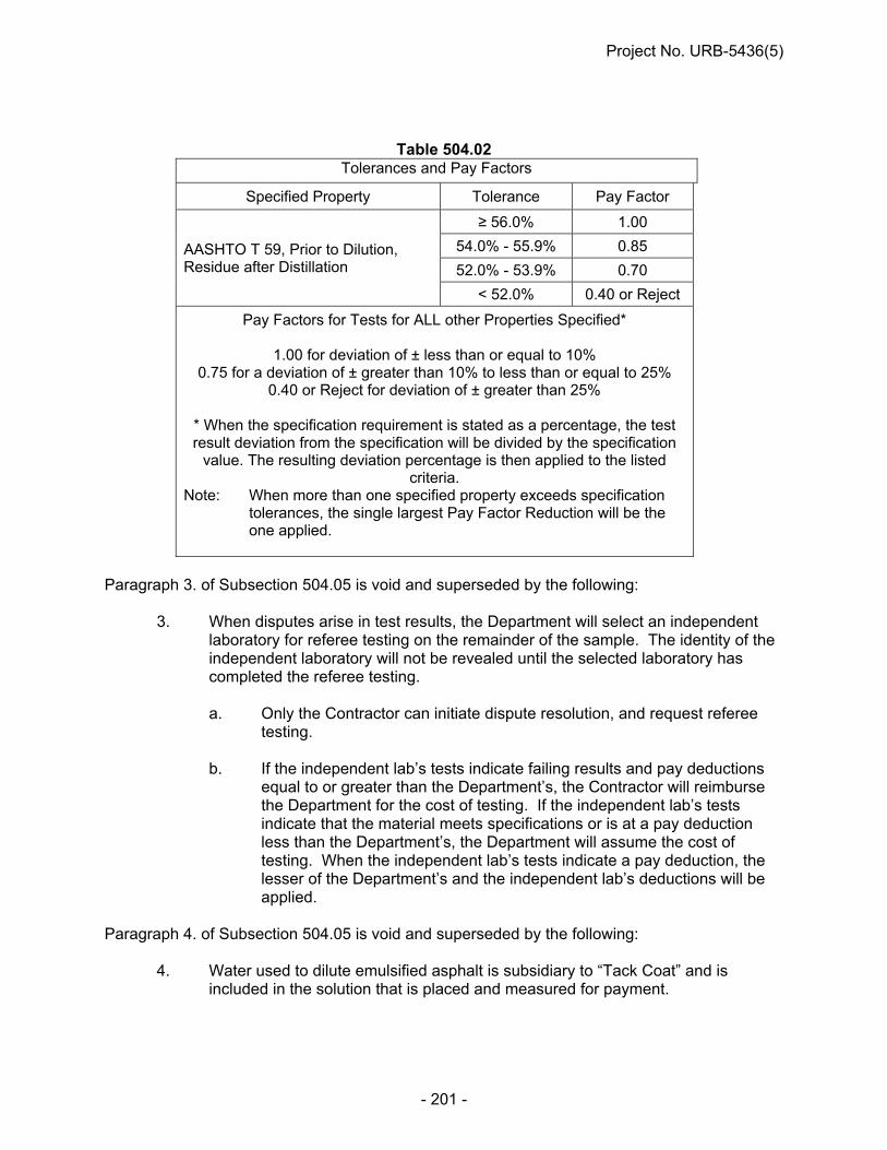
Project No. URB-5436(5)
- 201 -
Table 504.02 Tolerances and Pay Factors
Specified Property Tolerance Pay Factor
AASHTO T 59, Prior to Dilution, Residue after Distillation
≥ 56.0% 1.00
54.0% - 55.9% 0.85
52.0% - 53.9% 0.70
< 52.0% 0.40 or Reject
Pay Factors for Tests for ALL other Properties Specified*
1.00 for deviation of ± less than or equal to 10% 0.75 for a deviation of ± greater than 10% to less than or equal to 25%
0.40 or Reject for deviation of ± greater than 25%
* When the specification requirement is stated as a percentage, the test result deviation from the specification will be divided by the specification
value. The resulting deviation percentage is then applied to the listed criteria.
Note: When more than one specified property exceeds specification tolerances, the single largest Pay Factor Reduction will be the one applied.
Paragraph 3. of Subsection 504.05 is void and superseded by the following:
3. When disputes arise in test results, the Department will select an independent laboratory for referee testing on the remainder of the sample. The identity of the independent laboratory will not be revealed until the selected laboratory has completed the referee testing.
a. Only the Contractor can initiate dispute resolution, and request referee
testing.
b. If the independent lab’s tests indicate failing results and pay deductions equal to or greater than the Department’s, the Contractor will reimburse the Department for the cost of testing. If the independent lab’s tests indicate that the material meets specifications or is at a pay deduction less than the Department’s, the Department will assume the cost of testing. When the independent lab’s tests indicate a pay deduction, the lesser of the Department’s and the independent lab’s deductions will be applied.
Paragraph 4. of Subsection 504.05 is void and superseded by the following:
4. Water used to dilute emulsified asphalt is subsidiary to “Tack Coat” and is included in the solution that is placed and measured for payment.

Project No. URB-5436(5)
- 202 -
Subsection 504.05 is amended to include the following: 5. Payment is full compensation for all work prescribed in this Section.
BITUMINOUS PAVEMENT PATCHING (E-8-1212)
Paragraphs 1, 2 and 3 of Subsection 516.05 in the Standard Specifications are void and superseded by the following: 1. a. Bituminous Pavement Patching of flexible pavement and the repair or
replacement of any subgrade material authorized by the Engineer will be measured by one of the methods described in Paragraph 1.b. based upon the depth of the patch.
b.(1) For patches 16-inches (40cm) deep or less, determined at the time of patching,
the patching will be measured by the ton (megagram) of “Asphaltic Concrete for Patching, Type ___” required to complete the patch and repair any faulty subgrade. No equipment rental will be paid for this work, and all equipment used to complete the work shall be subsidiary to the item, “Asphaltic Concrete for Patching, Type ___.”
(2) For patches more than 16 inches (40cm) deep, determined at the time of
patching, the patching will be measured by the ton (megagram) of “Asphaltic Concrete for Patching, Type ___” required to complete the patch and repair any faulty subgrade. Additionally, the hours of equipment rental required to complete the patching and repair in that portion of the patch deeper than 16-inches will be measured by the hour of equipment rental in accordance with Section 919. Only approved equipment needed to patch and excavate the failure is to be rented, and only the time utilized to perform the work in the region deeper than 16-inches (40 cm) is to be measured. Excluded is any equipment needed to haul asphalt to the site.
2. a. Bituminous Pavement Patching of concrete pavement and the repair or
replacement of any subgrade material authorized by the Engineer will be measured by the square yard (square meter) of completed and accepted work regardless of depth. Additionally, the asphaltic concrete used to complete the patch will be measured for payment and included with the roadway tonnage.
b. Bituminous Pavement Patching of concrete pavement is divided into 3 types (see
Table 516.02). The types are based on the size of the individual patches constructed in a single lane. If a damaged area spans 2 or more lanes, then the continuous patch will be counted as multiple patches -- 1 patch per lane.
Table 516.02 Asphalt Patch Sizes in Rigid Pavement
Type Size A 5 SY (5 m2) or less B Greater than 5 SY to 15 SY (5 m2 to 12.5 m2) C Greater than 15 SY (12.5 m2)

Project No. URB-5436(5)
- 203 -
3. “Asphaltic Concrete, Type ____,” “Asphaltic Concrete for Patching, Type ___,”
“Asphalt Cement ____,” and “Hydrated Lime for Asphalt Mixtures” used in either the patching of flexible pavement or concrete pavement will be measured for payment by the ton (megagram) in accordance with Subsection 503.05.
DROP-OFF/COLD-MILLED TAPERED EDGE (E-8-0613)
Paragraph 7 of Subsection 107.07 is void and superseded by the following. 7. a. The Contractor shall conduct all operations to minimize any drop-offs (abrupt changes in
roadway elevation) exposed to traffic. b.(1) Unless otherwise specified in the Contract, drop-offs greater than 2 inches tall at the
shoulder edge that are adjacent to the traveled way shall be protected by a wedge of compacted stable material capable of carrying traffic (the wedge being 1 vertical to 3 horizontal or flatter). An edgeline warning stripe shall be placed on the traffic side of the drop-off.
(2) The Engineer shall authorize other methods, such as concrete barriers or Type II
barricades, to protect drop-offs when conditions do not allow a wedge of compacted, stable material.
(3) Unless otherwise ordered by the Engineer, drop-offs up to 2 inches (50 mm) may remain
exposed with appropriate warning signs alerting motorists to the condition. c. Open trenches which span all or part of the traveled way and/or auxiliary lanes shall be
no wider than 18 inches (450 mm) and must have a steel-plate cover placed and anchored over them. The plate shall have sufficient strength so as to only allow a maximum vertical deflection of 1/2 inch (12.5 mm). A wedge of suitable material shall create a smooth transition between the pavement and the steel plate. Warning signs shall be used to alert motorists to the presence of the steel plates.
Paragraph 3. b. of Subsection 510.04 is void and superseded by the following. 3. b. The Contractor shall not leave a milled vertical edge greater than 1-inch tall between
lanes overnight. One of the following options shall be performed if the milling will result in a vertical grade separation greater than 1 inch (25 mm) between lanes:
(1) Milling shall be performed in all adjacent traffic lanes on the same day so that at the end
of each day, no drop off of over 1 inch (25 mm) remains. (2) The milling shall create a tapered edge between the traffic lanes. The tapered edge
shall have a slope from 3 [H]: 1 [V] to 4 [H]: 1 [V], not measured more than one foot in width nor extend into the lane more than one foot. Temporary pavement marking shall be placed at the top and contiguous with the tapered edge.
c. If the Contractor fails to complete the above options, the Contractor shall provide – at no
cost to the Department – additional traffic control necessary to maintain traffic on the
Project No. URB-5436(5)
- 204 -
milled lane (or lanes) as directed by the Engineer. This additional traffic control may require the use of a pilot car, flaggers, lighted flagger station, etc.
d. Transitions between milled and unmilled in the direction of travel surfaces will be
feathered either by milling or with wedges of bituminous material (maximum slope 1 vertical to 12 horizontal).
OPTIONAL NOTCHED WEDGE JOINT (E-8-1013)
Description The Contractor has the option of constructing a notched wedge joint. If the Contractor chooses to construct this joint, it shall be built as shown on the plans and to the following requirements: Paragraph 5.e. of Subsection 503.04 is void if a notched wedge joint is
constructed between the adjacent traffic lanes. This work shall consist of constructing a notched wedge longitudinal joint between adjacent passes of asphaltic concrete lifts over 1” on pavement that will be open to traffic and contains uneven lanes. The notched wedge joint shall consist of a vertical notch ½ the thickness of the asphalt lift, and an 8” to 12” uniform taper extending into the adjoining lane (see plan typicals). Equipment 1. The notched wedge joint device shall be a manufactured strike-off device
attached to the asphalt paver screed and able to produce the required shape and configuration after compaction, as detailed in the plan typicals.
2. The device shall be self-adjusting, spring-loaded, and able to generate a smooth,
uniform surface and slope without disrupting the smoothness of the paving mat. 3. The device shall be capable of applying vertical loads by pressure or ballasting
methods. 4. The device may or may not have capability of vibration. Construction Method 1. The notched wedge joint device shall be heated prior to the beginning of laydown
either manually or as part of the notched wedge joint device. 2. The notched wedge joint shall be constructed in one pass of the paver. A
constant head of asphaltic concrete shall be supplied in front of the notched wedge to provide pre-compaction of the notched wedge joint.
3. The taper of the notched wedge joint will be a minimum of 8” and a maximum of
12”.

Project No. URB-5436(5)
- 205 -
4. The notched wedge joint shall be used at any longitudinal joint locations situated
between two driving lanes. The Contractor also has the option to utilize the notched wedge joint at other longitudinal joint locations.
5. A tack coat shall be applied to the full face of the in-place notched wedge joint,
prior to the placement of full lane tack coat application. Method of Measurement The construction of a notched wedge joint will not be measured and paid for but will be subsidiary to the associated asphaltic concrete.
TEMPORARY SURFACING 6” The work shall consist of the construction of the Temporary Surfacing on this project in accordance with plans, Standard Specifications and these Special Provisions. The Temporary Surfacing depth shall be as shown in the plans. This provision is applicable to all Temporary Surfacing depths shown in the plans. The finished surface shall not vary more than 1/8” as determined by using a ten foot straightedge, or other devices approved by the Engineer. The Contractor shall correct any depressions or high areas in excess of 1/8”. Prior to placing the Temporary Surfacing, prepare the underlying subgrade in accordance with the requirements of Section 302 of the Standard Specifications and these Contract Special Provisions. At the Contractor's option the Temporary Surfacing may be constructed using Class 47B-3500 Concrete or Asphaltic Concrete Type SPR. These materials may be used interchangeably during the course of the work except that surfacing at any individual location must be completed with the same material with which the work was begun. Asphaltic Concrete used for surfacing shall meet all specifications and sampled and tested as shown in the Standard Specifications or Special Provisions. Any asphaltic concrete not meeting the specifications will be subject to removal. Subsection 302.04 is amended to provide that the work of subgrade preparation, as well as all water applied as directed by the Engineer, will not be measured for payment, but shall be considered subsidiary to the item "Temporary Surfacing___". Subsection 304.04 is amended to provide that the work of shoulder construction, as well as all water applied as directed by the Engineer, will not be measured for payment, but shall be considered subsidiary to the item "Temporary Surfacing___”. Subsection 503.05 is amended to provide that Asphaltic Concrete and P.G. Binder used in the asphaltic concrete will not be measured for payment, but shall be considered subsidiary to the item "Temporary Surfacing___". Performance Graded Binder 64-22 may be used if asphaltic concrete is chosen as the temporary surfacing.
Project No. URB-5436(5)
- 206 -
Subsection 504.04 is amended to provide that the application of a tack coat, including furnishing emulsified asphalt, will not be measured for payment, but shall be considered subsidiary to the item "Temporary Surfacing___". Hydrated Lime for asphalt mixtures will not be measured for payment, but shall be considered subsidiary to the item “Temporary Surfacing ____”. Subsection 603.04 is amended to provide that concrete pavement will not be measured for payment, but shall be considered subsidiary to the item "Temporary Surfacing___". When the need for the temporary surfacing is no longer required the Contractor shall remove the temporary surfacing and it shall become the property of the Contractor and removed from the project. All the work necessary to accomplish this requirement is considered subsidiary to the item "Temporary Surfacing___". Measure temporary surfacing by the square yard of completed and accepted work. The work and materials required for temporary surfacing will be paid for at the contract unit price per square yard for the item “Temporary Surfacing___”. Payment will be full compensation for the work prescribed in these Special Provisions and the Standard Specifications.
Temporary Surfacing Thickness Cores
The Contractor will be required to core the Temporary Surfacing for final thickness determination. The cores will be cut prior to opening the temporary surfacing to traffic. One core shall be taken for each 3500 square yards, or fraction thereof, of temporary surfacing placed with a minimum of 1 core taken per project. The Engineer shall select the site where the core shall be taken. All work, materials and incidentals necessary to complete the work shall be considered subsidiary to the item “Temporary Surfacing ____”.
CONCRETE PAVEMENT CORING (F-17-0110)
Paragraphs 3. a. and 3.b. of Subsection 603.05 of the Standard Specifications are void
and superseded by the following:
3. a. (1) A pay factor will be applied to each unit based on the compressive strength of 1 core per unit tested in accordance with AASHTO T 24.
(2) Concrete cores must have a minimum age of 28 days before testing. (3) The paved area shall be divided into units, and each unit will be considered
separately. (4) Units are 750 linear feet (230 m) of pavement for each separately placed width
or width of each class of concrete whether or not placed separately starting at the beginning of the pavement.

Project No. URB-5436(5)
- 207 -
b. (1) When any unit core fails to have the required minimum compressive strength, the Contractor will have the option to obtain, at no cost to the Department, two additional cores from that unit provided that:
(i) The cores shall be cut by the contractor. (The cutting to be witnessed by
the Engineer) (ii) The cores shall be cut within seven (7) days of being notified of the
strength deficiency, and (iii) The cores shall be cut within 6 inches of the original unit core in the
longitudinal direction.
(2) The Engineer will take possession of the cores and have them tested within 24 hours at the Materials and Research laboratory.
(3) The results of all three cores sampled at the location will be averaged for the
final compressive strength calculation and pay factor. (4) The Department may agree to cut the additional cores if requested to do so by
the Contractor, but will do so only if the Department's coring crew is available on the project and has sufficient time to cut and transport the cores for testing during normal working hours within seven (7) days of the Contractor being notified of the strength deficiency.
Paragraph 4.a.(4) of Section 603.05 in the Standard Specifications is void and replaced by the following: A separately placed width is the width between field constructed longitudinal joints, between a longitudinal construction joint and the edge, or between two pavement edges. A separately placed width may include more than one pay class of concrete, such as doweled and non-doweled.
PORTLAND CEMENT CONCRETE PAVEMENTS GENERAL REQUIREMENTS
(F-20-0611) Paragraph 7.b. of Subsection 601.02 in the Standard Specifications is void and superseded by the following:
b. The finishing machine shall travel at a controlled speed such that it produces a uniform, well consolidated pavement that does not contain large voids.
Paragraph 10.d. of Subsection 601.02 is void and superseded by the following:
d. The Contractor shall always have a tachometer available to monitor vibrator frequency. The vibrator frequency shall be within the manufacturer’s specifications not to exceed 9,000 vpm.

Project No. URB-5436(5)
- 208 -
Paragraph 12.d.(1) of Subsection 601.02 is void and superseded by the following: (1) The mechanical joint saw shall have an adjustable guide to insure a true line is
cut. The mechanical joint saw blade shall be water-cooled, or specifically designed for early-entry sawing if air cooled.
Paragraph 12.d.(2) of Subsection 601.02 is void. Paragraph 12.d.(3) of Subsection 601.02 is void and superseded by the following:
d. (3) The joint cut shall be made with a diamond-toothed blade.
CONCRETE PAVEMENT (F-21-0611)
Paragraph 2.a. of Subsection 603.03 in the Standard Specifications is amended to include the following: (6) The base material shall be moistened through a uniform, lightly applied spray
pattern prior to concrete placement as directed by the Engineer. Paragraphs 2.d. and e. of Subsection 603.03 are void and superseded by the following: d. After being consolidated with internal mechanical vibration, the concrete shall be
struck off to a uniform height approximately 0.5 inch (12 mm) above the finished surface and then finished to the final elevation by means of a vibrating mechanical or vibrating hand operated screed.
e. Finished concrete shall be of uniform density with no segregation,
honeycombing, or large voids. Paragraph 3.f. of Subsection 603.03 is void and superseded by the following: f. (1) A wet burlap, carpet, or canvas drag will be drawn over the entire surface in a
longitudinal direction for a final finish, dampening of this drag material will be accomplished through a uniform, lightly applied spray pattern.
(2) The drag shall be suspended from a mandrel, or similar device, to insure a uniform texture.
(3) The drag shall be lifted from the surface of the concrete pavement when the paving train is not in motion for 30 minutes or more and carefully reset before resuming the dragging operations.
(4) Drags shall be rinsed or washed as necessary to obtain a uniform surface. Drags that cannot be cleaned shall be replaced.
Paragraphs 4.e., f., g., and h. of Subsection 603.03 are void and superseded by the following: e. For areas with pavement widening, dowel baskets shall be placed in all
transverse contraction joints which are 6 feet (1.8 mm) or wider.

Project No. URB-5436(5)
- 209 -
f. If normal vibration is found inadequate to thoroughly consolidate the plastic concrete within and around the dowel basket assemblies, adjustments to the material and/or operations shall be made.
g. Precautions shall be taken to assure that the sawed contraction joint is located
directly over the center of the dowel bars. h. Transverse cracks which form in the concrete pavement panels between load
transfer joints shall be stitched as shown in the plans, described in the Special Provision or repaired as directed by the Engineer. No payment will be made for this work.
Paragraph 6.b.(7)(i) of Subsection 603.03 is void and superseded by the following: (7) (i) The concrete shall be textured by dragging a wet burlap, carpet, or canvas belt
over the full width of the surface in a longitudinal direction. Dampening of this drag material will be accomplished through a uniform, lightly applied spray pattern.
Paragraph 6.c.(4)(i) of Subsection 603.03 is void and superseded by the following: (4) (i) The concrete shall be textured by dragging a wet burlap, carpet, or canvas belt
over the full width of the surface in a longitudinal direction. Dampening of this drag material will be accomplished through a uniform, lightly applied spray pattern.
Paragraph 7.a.(3) of Subsection 603.03 is void and superseded by the following: (3) (i) The curing compound shall be applied in 2 equal applications immediately
following each other or other methods approved by the Engineer. (ii) The total rate of applications shall be at a minimum of 1 Gal/100 SF (0.3 L/m2) of
surface area for tined surfaces or 1 Gal/150 SF (0.2 L/m2) of surface area for all other finishes.
Paragraph 8.a.(6) of Subsection 603.03 is voided and superseded by the following: (6) Any panels that contain random cracking will be considered unacceptable. The
Engineer will decide whether to replace or repair the panel. The Contractor shall replace or repair these panels at the direction of the Engineer at no cost to the Department. A 20% deduction will be assessed on any repaired panel. Any panel that is replaced will not be assessed a 20% deduction.
Paragraph 8.d.(3) of Subsection 603.03 is void. Paragraphs 8.d.(4), (5) and (6) of Subsection 603.03 are void and superseded by the following: (4) Before sealing, the joint wall (not the bottom of joint) surfaces shall be
sandblasted or water-blasted to remove all dirt, curing compound residue, laitance, and any other foreign material. After sandblasting, the entire joint shall be cleaned with compressed air having a minimum pressure of 90 psi (620 kPa).

Project No. URB-5436(5)
- 210 -
The compressed air shall be free of oil, water, and other contaminants. The joints shall be dry at the time of sealing.
(5) (i) Transverse contraction joints in Portland cement concrete pavements shall be sealed so that the joint is filled to approximately 1/8” to 3/8” (3 to 9 mm) below the top of the joint with an approved hot poured sealant.
(ii) All overflow material shall be removed from the surface of the pavement. (iii) If adhesion is not satisfactory, the material shall be rejected. (6) The Contractor shall give the Engineer one copy of the hot pour manufacturer’s
sealing recommendations. Paragraph 9.b. of Subsection 603.03 in the 2007 edition of the NDOR Standard Specifications for Highway Construction is void and superseded by: b. When the pay item “Portland Cement Concrete Smoothness Testing” is not
included in the contract, the Contractor shall test the hardened concrete for surface irregularities with a California Profilograph. Areas showing high spots (bumps) in excess of 0.30 inches in a 25 foot span will be plainly marked on the pavement and on the printed pavement profile trace. All identified high spots shall be ground to the required profile. The grinding shall be performed so that the cement-aggregate bond is not broken. The equipment and profilograph test procedure requirements of Section 602 of the Standard Specifications for Highway Construction shall apply to this surface testing.
Paragraph 9.c of Subsection 603.03 is amended to include: c. At the Engineer’s option, the use of a 10 foot straightedge to locate high spots in
excess of 1/8 inch may be allowed in lieu of bump detection using a profilograph testing.
Paragraphs 11.c., d. and e. of Subsection 603.03 are void and superseded by the following:
c. The Contractor’s forces may be allowed on the concrete pavement when the concrete has reached a minimum age of 14 days or when the concrete has reached a compressive strength of 3000 psi (24 MPa) when tested in accordance with ASTM C 39.
d. With the approval of the Engineer, the Contractor may elect to increase the early strength of the concrete by adding cement and/or reducing the water/cement ratio, and then the pavement may be opened to traffic provided it has attained a compressive strength of 3500 psi (24 MPa). The concrete in the area where the early strength is required shall be paid for at the bid price.
e. When required by the Special Provisions or when requested by the Contractor, the maturity method, as provided for in ASTM C 1074, may be used in lieu of the requirements of Subsection 603.03, Paragraph 10.c. and d. to determine the strength of concrete pavement for the purpose of early opening to traffic. Requests by the Contractor for use of the maturity method shall be on a project basis and shall be made in writing to the Materials and Research Engineer. The Contractor shall be responsible to coordinate with the Materials & Research Division to develop the maturity curve.

Project No. URB-5436(5)
- 211 -
Paragraph 3.a. and b. of Subsection 603.05 is void and superseded by the following:
3. a. A pay factor will be applied to each unit based on the compressive strength of 1 core per unit tested in accordance with AASHTO T 24. Concrete cores must have a minimum age of 28 days before testing. The Contractor will have the option to obtain two additional cores for any unit core that fail to have the required minimum compressive strength provided that the cores are:
(1) Obtained and tested within seven (7) days of being notified of the strength
deficiency, under the supervision of the Engineer. (2) Cut within 6 inches of the original unit core in the longitudinal direction.
The results of all three cores sampled at the location will be averaged for the final compressive strength calculation and pay factor.
b. The paved area shall be divided into units. Each unit will be considered separately. Units are 750 linear feet (230 m) of pavement for each separately placed width, or width of each class of concrete whether or not placed separately starting at the beginning of the pavement.
Paragraph 4.a.(7) of Subsection 603.05 is void and superseded by the following: (7) A the option of the Engineer, cores may not be required from irregular areas with
widths less than 8 feet (2.4 m) or from an individual pavement type that involve less than 5,000 square yards (4200 m2) of pavement.
Paragraph 4.c.(4) of Subsection 603.05 is void and superseded by the following: (4) If the average thickness of the cores is deficient by more than 0.25 inch (6 mm)
but not more than 0.50 inch (12.5 mm) an adjusted unit price will be paid in accordance with Table 603.04. Cores deficient by more than 0.50 inch (12.5 mm) will be treated as prescribed in Paragraph 4.d. of this Subsection.
CONCRETE HEADWALL Paragraph 1. of Subsection 704.05 in the Standard Specifications is amended to include the following:
Pay Item Pay Unit Concrete Headwall at ____ Each (ea)
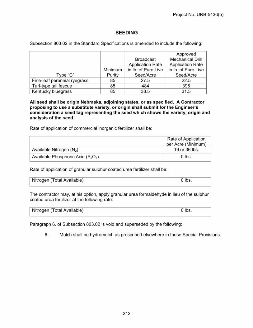
Project No. URB-5436(5)
- 212 -
SEEDING Subsection 803.02 in the Standard Specifications is amended to include the following:
Type “C” Minimum
Purity
Broadcast
Application Rate in lb. of Pure Live
Seed/Acre
Approved Mechanical Drill Application Rate in lb. of Pure Live
Seed/Acre Fine-leaf perennial ryegrass 85 27.5 22.5 Turf-type tall fescue 85 484 396 Kentucky bluegrass 85 38.5 31.5
All seed shall be origin Nebraska, adjoining states, or as specified. A Contractor proposing to use a substitute variety, or origin shall submit for the Engineer’s consideration a seed tag representing the seed which shows the variety, origin and analysis of the seed. Rate of application of commercial inorganic fertilizer shall be: Rate of Application
per Acre (Minimum) Available Nitrogen (N2) 19 or 36 lbs.
Available Phosphoric Acid (P2O5) 0 lbs.
Rate of application of granular sulphur coated urea fertilizer shall be: Nitrogen (Total Available) 0 lbs.
The contractor may, at his option, apply granular urea formaldehyde in lieu of the sulphur coated urea fertilizer at the following rate: Nitrogen (Total Available) 0 lbs.
Paragraph 6. of Subsection 803.02 is void and superseded by the following: 6. Mulch shall be hydromulch as prescribed elsewhere in these Special Provisions.

Project No. URB-5436(5)
- 213 -
EROSION CONTROL Subsection 807.02 in the Standard Specifications is amended to include the following:
Erosion Control Minimum
Purity
Application Rate in lb of Pure Live Seed/1000 sq.
yard Fine-leaf perennial ryegrass 85 4.7 Turf-type tall fescue 85 81.8 Kentucky bluegrass 85 6.5
All seed shall be origin Nebraska, adjoining states, or as specified. A Contractor proposing to use a substitute variety, or origin shall submit for the Engineer’s consideration a seed tag representing the seed which shows the variety, origin and analysis of the seed. Rate of application of commercial inorganic fertilizer shall be:
Rate of Application per 1000 SY (Minimum)
Available Nitrogen (N2) 4 or 9 lb.
Available Phosphoric Acid (P2O5) 0 lb.
Rate of application of granular sulphur coated urea fertilizer shall be:
Nitrogen (Total Available) 0 lb.
EROSION CONTROL Subsection 807.01 is void and superseded by the following: This work shall consist of the preparation of slopes and waterways and the furnishing
and application of soil retention blankets at the locations shown in the plans. Subsection 807.02
Paragraphs 2., 2.a., 2.b. and 2.c. are void and superseded by the following: Wire staples shall be used for anchoring the soil retention blanket. The staples
shall be a minimum of 13 gauge U-shaped steel wire with a 1 inch or larger throat with at least 6 inch long legs.
Paragraph 5. is void.
Project No. URB-5436(5)
- 214 -
Subsection 807.03 Paragraph 6.c. is void. Paragraphs 7.a.i. and 7.a.ii. are void. Paragraph 8. is void. Paragraph 1. of Subsection 807.05 is amended to include the following: Pay Item Pay Unit
Erosion Control, Class_______ Square Yard (SY)
HYDROMULCHING Description This work shall consist of furnishing, hauling, placing and securing hydromulch on areas shown in the plans or identified by the Engineer as being seeded in accordance with Section 803. Material Requirements 1. Hydromulches shall be as shown in the plans and selected from the Approved Products
List. a. Bonded Fiber Matrix (BFM) is a hydraulically-applied matrix containing organic
defibrated fibers and cross-linked insoluble hydro-colloidal tackifiers to provide erosion control and facilitate vegetation establishment. The products are designed to be functional for a minimum of 6 months.
2. The Hydromulch shall be delivered to the site in packaging that clearly states the
manufacturer’s name and product. The packaging shall also clearly state the weight per bag.
3. The Contractor shall obtain the necessary water required for the hydromulching
operation. The Contractor shall notify the Engineer as to where he/she proposes to obtain the water.
Construction Methods 1. The Contractor shall apply the mulch within 24 hours after planting the seed, unless
otherwise directed by the Engineer. The mulch shall be applied uniformly over tilled areas with a hydromulch machine.
2. Application Rates:
a. Bonded Fiber Matrix (BFM) shall be applied at 1.5 tons per acre. 3. The Contractor shall refer to the mulch manufacturer’s recommendations for appropriate
mulch to water ratios.

Project No. URB-5436(5)
- 215 -
4. The mulch shall be applied in a manner to ensure uniform coverage. Generally this
requires spraying from two different directions. Method of Measurement 1. The weight of the hydromulch is measured in tons (Megagrams). 2. The weight of hydromulch applied is calculated by multiplying the measured area times
the combined weight of the number of bags used. 3. Quantity Determination: a. When the total weight of hydromulch is within 5 percent of the calculated weight,
then the pay quantity will be the calculated weight. b. When the Engineer directs in writing the application of a weight greater than the
calculated weight, then the Department will pay for the revised calculated weight of hydromulch.
c. When the weight of hydromulch applied is less than 95 percent of the calculated
weight, then additional hydromulch will be required to be applied to the site. d. If the Contractor applies more hydromulch than directed by the Engineer, then
the weight over 100 percent of the specified weight or the amount directed by the Engineer is provided at no additional cost to the Department.
Basis of Payment 1. Pay Item Pay Unit Hydromulch Ton (Tn) [Megagram (Mg)] 2. Payment is full compensation for all work prescribed in this Section.
COVERCROP SEEDING Subsection 812.01 Paragraph 2. is void and superseded by the following: Cover crop seeding shall be applied to any disturbed area requiring erosion
protection. It is intended to be used in staged construction areas, surcharge areas, or other disturbed areas that have not been permanently seeded.
Subsection 812.02 Paragraph 4. is void.

Project No. URB-5436(5)
- 216 -
Subsection 812.04 is void and superseded by the following:
Subsection 812.04 1. Cover crop seeding is measured by the acre of ground surface seeded. The
areas will be calculated from surface measurements of the length and width + 1 yard (+ 900 mm).
SODDING Section 806 of the Standard Specifications is void and superceded by the following: Description 1. This work shall consist of furnishing, fertilizing, watering, and placing bluegrass sod in
accordance with these Specifications, the plans, and the Special Provisions. 2. Sodding operations shall not be performed between June 1 and September 1, when the
ground is frozen, or when weather conditions are not favorable for growth as determined by the Engineer.
3. The sod shall be harvested, delivered and installed within a period of 24 hours, unless a
suitable preservation method is approved by the Engineer. Material Requirements 1. The sod shall be grown at a sod farm, licensed by the Department of Agriculture,
approved by the Engineer. A certification of origin shall accompany each load delivered to the project site.
2. The sod shall have been grown from more than one variety of bluegrass seed, grown
specifically for the production of bluegrass sod, and maintained by accepted sod production methods.
3. Cutting:
a. Prior to harvesting, the sod shall be mowed uniformly at a height of 1 to 2.5 inches (25 to 60 mm).
b. The sod shall be machine cut at a uniform soil thickness of 0.60 inch (15 mm),
plus or minus 0.25 inch (6 mm), at the time of cutting. Measurement for thickness shall exclude top growth and thatch.
c. All sod shall be free from noxious weeds and all other weeds.
d. Individual pieces of sod shall be cut to the supplier’s standard width and length.
Broken pads and those with torn or uneven ends will not be accepted.
e. The sod shall not have dry or dead edges.

Project No. URB-5436(5)
- 217 -
4. Fertilizer:
a. The composition and rate of application of fertilizer shall be a minimum of 8 lbs of available Nitrogen (N2) and 23 lbs of available Phosphoric Acid (P2O5) per 1000 square yards.
5. The acceptable pre-emergent weed control chemicals shall be Dacthal, Siduron or other
approved weed control chemicals. Weed control chemicals should be applied at the midrange of the manufacturer’s suggested rate of application.
Construction Methods 1. The area to be sodded will be shown in the plans or as directed by the Engineer. 2. Subject to the dates established in this Section, the Contractor shall place the sod
immediately after the finish grading work has been completed and approved by the Engineer for a section of the project.
3. Site preparation:
a. The Contractor shall clear all areas to be sodded of debris and dead vegetation before the sod bed is prepared.
b. The soil shall not be crusted.
c. All eroded areas shall be filled and loose earth firmed before laying the sod.
d. The area to be sodded shall be graded smooth and free of debris, including roots, stones and clods larger than 1 inch (25 mm) in their largest dimension.
e. Topsoil, when specified, shall be spread and tilled into the soil by discing or other
methods to the depth shown in the Special Provisions or the plans. 4. The sod bed shall be approved by the Engineer before laying the sod. 5. The sod shall be laid over the area with strips edge to edge in a compact mass. The sod
shall be laid approximately 1 inch (25 mm) below adjoining ground surfaces and flush with the adjoining sod.
6. All sod placed on slopes steeper than 1 vertical to 3 horizontal and in ditch bottoms shall
be adequately staked by the Contractor to prevent slippage. The stakes shall be wood-lathe and shall be at least 8 inches (200 mm) in length. Stakes shall be driven flush with the sod line and with the broad face of the stake facing the slope. Other types of stakes may be used with the approval of the Engineer.
7. Fertilizer and Herbicide:
a. The Contractor shall apply fertilizer and/or a pre-emergent herbicide of the type shown in the Special Provisions over the top of the sod immediately after laying the sod and before watering.

Project No. URB-5436(5)
- 218 -
b. The rate of application shall be as shown in Special Provisions. c. The pre-emergent is not required on sod laid after September 1.
d. All excess herbicide or fertilizer, which falls onto adjacent streets, sidewalks, parking or other pavements, shall be swept and/or removed to prevent it from being washed into adjacent drainages.
8. The Contractor shall thoroughly water all sod immediately after placing fertilizer and/or
pre-emergent herbicide. Watering may also be required during the work operations to cool the sod.
9. Establishment Period:
a. The Establishment Period shall begin upon installation of all sod in a section designated on the plans or agreed upon by the Engineer. The Establishment Period shall be 30 days. All sod must be growing at the time of acceptance.
1. Sod layed after October 15 will be inspected between April 1 and April 15
of the following year.
b. The Contractor shall keep all sodded areas thoroughly watered for 30 calendar days after layed. Watering may be necessary multiple times within a day to ensure survivability. Watering required by the Engineer after 30 days will be extra work.
c. If, at the end of the establishment period, the growth or stand of the sod is
deemed unacceptable by the Engineer, the sod shall be rejected. The Engineer will determine whether the rejected sod is to be replaced or reseeded.
d. Rejected Sod:
(1) Rejected sod may be replaced or overseeded with a mixture of rye and
bluegrasses or other suitable mixtures as determined by the Engineer. (2) The replacement and overseeded sod shall be accepted: a. when the resodded areas are determined to be growing
b. when the overseeded areas have achieved a 70% cover with a uniform stand of the specified perennial vegetation.
(3) The Contractor shall water replacement and overseeded sod for 30 calendar days. Watering required by the Engineer after 30 days will be extra work.
(4) There will be no extra compensation for replacement sod, overseeding or watering the areas where the sod was rejected.
10. The Contractor shall apply the post-sodding fertilizer at the end of the establishment
period. Method of Measurement The sod shall be measured for payment by the number of square yards (square meters) of surface area of sod furnished and placed.

Project No. URB-5436(5)
- 219 -
Basis of Payment 1. Pay Item Pay Unit Sodding Square Yards (SY) [Square Meter (m2)] 2. Payment is full compensation for all work prescribed in this Section.
INLET PROTECTION Description This work shall consist of installing, maintaining, and removing manufactured or site constructed curb inlet and area inlet protection devices at locations shown on the plans, temporary erosion control plans, or as directed by the Engineer. Material Requirements 1. Inlet protection devices shall be constructed as shown in the plans. 2. Manufactured inlet protection devices shall be selected from the NDOR Approved
Products List. Construction Methods 1. Inlet protection shall be manufactured or site constructed devices.
a. Inlet protection shall be the type shown on the plans, temporary erosion control plans, or approved by the Engineer.
b. Approved manufactured products shall be installed as per manufacturer's
recommendations. The Engineer shall be given a copy of the instructions before installation.
c. Site constructed protection shall be approved by the Engineer.
d. Inlet protection devices shall be installed in a manner to prevent ponding of
stormwater on the roadway. 2. Inlet protection devices shall be maintained, repaired, and repositioned to provide
effective protection.
a. The Contractor shall remove and dispose of sediment that accumulates near the inlet protection device when it is at 50% capacity on closed roadways.
b. The Contractor shall remove and dispose of all sediment from the roadway within
24 hours of the end of a storm event on roadways open to traffic. 3. Inlet protection devices shall be removed at the completion of the project, or when the
Engineer determines it is no longer effective, or as directed by the Engineer.

Project No. URB-5436(5)
- 220 -
Method of Measurement 1. Area Inlet Protection will be measured based on each location installed. 2. Curb Inlet Protection will be measured based on the “Y” Distance of each new or existing
curb inlet. 3. Silt removal will be measured based on equipment rental. 4. Maintenance, repair, repositioning and any handwork required in the maintenance
operation of an inlet protection device to a good working condition will not be measured for payment, but will be considered subsidiary to the appropriate inlet protection item.
5. Removal of inlet protection devices shall be subsidiary to the installation of the item. Inlet
protection devices shall remain the property of the Contractor. Basis of Payment 1. Pay Item Pay Unit Area Inlet Sediment Filter Each Curb Inlet Sediment Filter Linear Foot
Rental of Skid Loader, Fully Operated Hour Rental of Loader, Fully Operated Hour
Rental of Crawler Mounted Hydraulic Excavator, Fully Operated Hour Rental of Dump Truck, Fully Operated Hour 2. Payment will not be made for individual components of the device installed. 3. Payment is full compensation for all work prescribed in this Section.
SILT CHECKS Description 1. This work shall consist of furnishing and placing silt check devices at the locations
shown in the plans, Temporary Erosion Control Plans or as directed by the Engineer. Bale Checks shall not be allowed.
2. There are two separate and distinct types of silt checks.
a. Silt Checks are placed as shown in the plans or as directed by the Engineer after final grading is complete in conjunction with the final stabilization.
b. Temporary Silt Checks are placed as shown in the Temporary Erosion Control
plans or as directed by the Engineer throughout the construction process.

Project No. URB-5436(5)
- 221 -
Material Requirements 1. Approved silt check devices are listed in and shall be selected from the Approved
Products List.
a. Silt Checks used for final stabilization shall be the type shown in the plans and selected from the Approved Products List.
b. Temporary Silt Checks may be any product listed on the Approved Products List.
The following chart shall be used to determine the appropriate application of Temporary Silt Checks during construction.
Type Material Ditch Grade
Uses/Locations
1 – Low
9 “ Diameter Straw Wattle
< 2 % Medians, Slopes and Urban Ditches
1 – High
12” Diameter Straw Wattle
< 2 % Wetlands, Stream Banks, Slopes and Rural Ditches
2 – Low 9” Diameter Wood Fiber Wattle
All Medians and Urban/Rural Ditches
2 - High 12” Diameter Wood Fiber Wattle
All Wetlands, Stream Banks, and Rural Ditches
3 – Low
9” Diameter Coir Wattle
All Slopes, and Rural Ditches
3 – High
>12” Diameter Coir Wattle
All Wetlands, Stream Banks, Slopes and Rural Ditches
4 Synthetic All Urban Ditches 2. All silt check devices have unique staking or pinning requirements based upon the BMP
and its use. The hold down stakes and pins shall be as shown on the Silt Check Detail Sheet.
Construction Methods 1. The silt checks shall be placed as shown in the plans or as directed by the Engineer and
secured in accordance with the plans. 2. The limits of the completed silt check shall extend up the foreslope and backslope of the
ditch to effectively contain the run-off and prevent erosion and washout at the edges of the installation as shown on the Silt Check Detail Sheet.
3. Temporary Silt Checks
a. The “Temporary Silt Checks” shall be installed at the locations shown in the plans, Temporary Erosion Control Plan and as directed by the Engineer.
b. The “Temporary Silt Checks” shall be installed immediately after the rough
grading is completed in an area.

Project No. URB-5436(5)
- 222 -
c. The “Temporary Silt Check” shall be left in place until the finish grading begins. Reinstall the “Temporary Silt Checks” as soon as finish grading is done unless the permanent erosion control is initiated immediately after finish grading. “Temporary Silt Checks” should be in place at all times after finish grading until permanent “Silt Check,” are in place.
d. The Temporary Silt Check shall be removed and remain the property of the
Contractor when it is no longer functional or needed. Method of Measurement 1. All work involved in constructing silt checks as described above will be included and paid
for per linear feet of devices used in the silt checks. 2. “Temporary Silt Checks” shall be measured by the linear foot (meter) for the initial
installation. The removing or replacing of the temporary silt checks will not be measured for payment, but will be considered subsidiary to the initial installation.
3. Removal of sediment will be measured based on equipment rental. All incidentals
associated with the cleanout shall be subsidiary to the equipment rental items. Basis of Payment 1. Pay Item Pay Unit Silt Check, Type _____ Linear Foot Temporary Silt Check Linear Foot Rental of Skid Loader, Fully Operated Hour Rental of Loader, Fully Operated Hour Rental of Crawler Mounted Hour Hydraulic Excavator, Fully Operated Rental of Dump Truck, Fully Operated Hour 2. Payment is full compensation for all work prescribed in this Section.
SILT FENCE Section 809 of the Standard Specifications is void and superseded with the following: Description This work shall consist of installing the silt fence at locations shown in the plans and at locations as approved or determined by the Engineer. The installation shall be in accordance with these Specifications, the special provisions, and the plans. Material Requirements 1. All silt fence material shall be selected from the NDR Approved Products List. a. Low Porosity Silt Fence is typically used for perimeter control.

Project No. URB-5436(5)
- 223 -
b. High Porosity Silt Fence is used for velocity control. c. Low Profile Silt Fence is used for perimeter control and inlet protection
d. Coir Silt Fence is used for perimeter control of wetlands and locations specified to use a biodegradable silt fence.
e. Temporary Silt Fence shall be any product from the silt fence category of the
Approved Products List with a use appropriate to the situation. 2. Silt Fence Posts
a. The silt fence posts shall be Studded “T” Steel Posts with a minimum weight of 1.25 lbs/foot (37 Kg/m).
b. Used Studded “T” Steel Posts are acceptable.
c. Coir Silt Fence shall be installed with wooden posts, derived from hardwood tree species. The posts shall only be driven until firm.
3. Wire staples shall be used for anchoring the silt fence. 4. Silt Fence shall be attached to the posts with black zip ties. Zip ties shall be UV
stabilized, black with a 50 lb (22 Kg) minimum tensile strength. Construction Methods 1. The silt fence shall be installed and in good working condition prior any grading or
excavation operations and as needed throughout the construction process. The silt fence installation shall not exceed the amount required for the current construction season.
2. Silt Fence may be installed in the ground by either of the two methods listed below. a. Trenching Method
(i) The Contractor shall excavate a trench to the depth, width, and length shown in the plans.
(ii) The Contractor shall place the silt fence in the trench and pin it as shown in the plans.
(iii) The Contractor shall backfill the trench, compact the soil, and attach the fabric to the posts as shown in the plans.
b. Slicing Method
(i) The Contractor shall install silt fence by mechanically slicing the material into the soil.
(ii) The Contractor shall compact the soil and attach the fabric to the posts as shown in the plans.

Project No. URB-5436(5)
- 224 -
3. Fabric Silt Fence installed in a wetland or below water conditions.
a. Trenching is not required. Fold a 6 inch (150 mm) flap toward the sediment source and pin as shown in the plans. Install the stakes as for a dry installation. Attach the fabric to the posts with zip ties or other approved methods and secure from slipping down the post. For a wetland or below water installation, the sediment shall be left in place.
4. All silt fence splice joints shall be overlapped a minimum of 6 feet (1.8 m). 5. The Contractor shall remove sediment that accumulates near the silt fence during
construction and dispose it in an upland location.
a. Sediment removal shall be initiated when sediment depth has reached one-half the height of the above ground portion of the silt fence or as directed by the Engineer in conjunction with silt fence repairs.
b. Sediment shall be removed to approximately 6 inches (150 mm) from the silt
fence. c. Each time sediment is removed, the silt fence shall be repaired to a good working
condition. Good working condition includes fabric repair, retrenching, post repair, tie replacement, and any associated hand work.
6. The Contractor shall maintain the silt fence in good working condition throughout the life
of the construction project. Upon completion of the project silt fence shall remain in place in good working condition, in locations specified in the plans or at locations specified by the Engineer.
a. Silt fence may be removed from locations during construction or upon completion
of the project as directed by the Engineer.
b. Silt fence that has been determined to be unnecessary and is subject to removal shall be cut off at ground level and shall remain the property of the Contractor for disposal. Any accumulated sediment shall be removed to an upland location.
c. Silt fence posts from removed fence shall remain the property of the Contractor
and may be reused on other installations.
d. Temporary Silt Fence shall be removed at the completion of the project or when it is no longer functional.
Method of Measurement 1. Fabric silt fence is measured by the length of the silt fence in linear feet (meter). 2. Removal of sediment from the silt fence will be measured based on equipment rental. 3. All silt fence repairs, such as fabric repair, tie replacement, retrenching, and splicing and
associated handwork are subsidiary to the appropriate silt fence item.

Project No. URB-5436(5)
- 225 -
4. Removal of silt fence and all of its components is subsidiary to the Basis of Payment 1. Pay Item Pay Unit Fabric Silt Fence “Low Porosity” Linear Foot (LF) [Meter (m)] Fabric Silt Fence “High Porosity” Linear Foot (LF)
[Meter (m)] Fabric Silt Fence “Low Profile” Linear Foot (LF) [Meter (m)]
Fabric Silt Fence “Coir Fiber” Linear Foot (LF) [Meter (m)] Temporary Silt Fence Linear Foot (LF) [Meter (m)]
Rental of Skid Loader, Fully Operated Hour (h) Rental of Loader, Fully Operated Hour (h) Rental of Dump Truck, Fully Operated Hour (h) Rental of Crawler Mounted Hydraulic Hour (h) Excavator, Fully Operated 2. Payment is full compensation for all work prescribed in this Section.
CONCRETE DITCH LINING Paragraph 1. of Subsection 908.05 in the Standard Specifications is amended to include the following:
Pay Item Pay Unit Concrete Ditch Lining ___ Square Yard (SY)
PERFORMANCE GRADED BINDER Section 503 in the Standard Specifications is amended to include Performance Graded Binders. Section 1029 in the Standard Specifications is void and superseded by the following: I. Description The Performance Graded Binder to be used on this project shall be PG Binder 64-22
supplied by a Certified Supplier.

Project No. URB-5436(5)
- 226 -
II. Certified Supplier A supplier must be certified by the Nebraska Department of Roads to be allowed to
supply Performance Graded Binder in Nebraska. To be considered certified by the NDR, a supplier must participate in one or more of the following PG Binder groups.
1. AASHTO Materials Reference Laboratory (AMRL) 2. Western Cooperative Testing Group (WCTG) 3. Combined States Binder Group (CSBG)
The supplier must also maintain and follow the requirements of the group or groups in
which they participate in, to maintain certification by the Nebraska Department of Roads. In addition, active participation is required to maintain certification by the Department. Active participation will include submitting of round robin sample results, along with meeting other requirements of the group or groups.
A certified supplier may be asked to supply to the Department, past round robin results,
laboratory inspection reports, reasons for and investigative reports on out lying results, quality control testing, and/or technician training and proficiency testing reports.
The binder supplier agrees to inspection of their plant or terminal without notice anytime
during production or supplying of material to the Department. The inspection may also include the supplier’s laboratory.
A certified supplier can voluntarily submit samples of binders proposed for use to the
Materials and Research Bituminous Laboratory for quality and verification testing. III. Supplier Certification A supplier may request certification by contacting the Nebraska Department of Roads,
Materials and Research Division, Flexible Pavement Engineer at (402) 479-3839. A temporary certification may be issued for a period of up to one year. Split sample testing will be required prior to receiving a temporary certification. Split sample testing will be done on all grades of binder that the supplier intends to supply during the temporary certification. The supplier will have up to one year to become certified by participating in and following the requirements of one or more of the approved binder groups.
A supplier may become certified through active participation in other binder
certification/round robin groups that are approved by the NDR. The NDR may request from the supplier prior to approval, past or current round robin results, quality control testing, laboratory inspection reports, and/or technician training and proficiency testing reports.
IV. Loss of Certification Certification will be withdrawn from a supplier for a minimum of 6 months when one or
more of the following conditions exist. 1. Inability to consistently supply material meeting specifications as outlined herein. 2. Failure to maintain an acceptable quality control program.

Project No. URB-5436(5)
- 227 -
3. The failure to meet one or more of the conditions of being a Certified Supplier as
outlined above. Notification of decertification of a supplier will be submitted in writing by the NDR.
Material from a decertified source will not be accepted for use on NDR projects and the NDR districts will be notified of this action.
V. Supplier Recertification If a supplier has lost certification and seeks to be recertified, the following steps are
required. 1. Fulfill the requirements outlined above for gaining Certified Supplier status.
2. Submit documentation to the Flexible Pavement Engineer explaining why decertification occurred, and the actions that are going to be taken to correct the problems identified in writing by the NDR.
VI. Binder Sampling and Testing:
1. Lots: Each 3750 tons (3400 Mg) of HMA type produced, or portion thereof, will be a binder lot.
2. A binder lot will include only one PG Binder grade or a blend as allowed in
paragraph VI.6.e.
3. A binder lot will only include one supplier of the PG Binder or a blend as allowed in paragraph VI.6.e.
4. Blending of different binder grades and binders from different suppliers will be
allowed with restrictions as noted in paragraph VI.6.e. The Engineer must be notified of the intent to blend prior to actual blending.
5. All binders shall be sampled at the rate of at least one sample per lot.
a. The sample shall consist of two one-quart (liter) cans and shall be taken
by the Contractor's Certified Sampling Technician, with assistance from or under supervision of NDR personnel. The sample shall be taken at the plant from the line between the storage tank and the mixer or from the tank supplying material to the line, at a location at which material sampled is representative of the material in the line to the mixer. One can will be tested for specification compliance, and the other can portion will be saved for check tests and dispute resolution, if needed. The sampling process shall follow procedures of the NDR Materials Sampling Guide.
b. Testing. When the tested PG Binder is in compliance, the binder lot will
be accepted and both cans of the sample can be discarded. If the tested PG Binder does not comply, then the price of the PG Binder lot represented by the sample shall be adjusted according to Tables 2 and 3.

Project No. URB-5436(5)
- 228 -
Overall project average testing requirements and price adjustments will also apply, as stated in Table 4.
c. In cases where the total HMA type is less than 3750 tons, only one PG
Binder lot sample per grade per supplier is required. If the tested PG Binder does not comply, the price of the PG Binder lot shall be adjusted according to Tables 2 and 3.
6. Material Requirements
a. Performance Graded Binder, as specified in the contract items, shall be in
accordance with the PG+ specifications as noted, and AASHTO M320 with the exception of Direct Tension.
b. Substitution of a PG Binder, which exceeds the upper and lower grade
designations from the specified, requires advance notification to, and approval by, the Engineer. The substitution of the PG Binder shall also be identified in the sample identification submittals.
c. Material Certification - A Material Certification shall be submitted prior to
construction, stating the type of modifier being used, and the recommended mixing and compaction temperatures for the Hot Mix Asphalt. The Material Certification must state that acid has not been used. The Material Certification must also state that the material has not been air blown or oxidized.
d. The Contractor shall receive from the supplier, instructions on the proper
storage and handling of each grade and shipment of PG Binder.
e. Blending of PG Binders at the hot mix plant site will be allowed only when transitioning to an asphalt mixture requiring a different grade of binder, and with the following restrictions:
(1) The resultant blend will meet PG+ (modified binders) and/or
AASHTO M320 specifications when tested as ±3° C of the specified PG Binder. The sample of the blended material 1) will be considered as a lot sample, 2) will be taken during initial production following the blending of the binders, and 3) shall have deductions applied as per Tables 2, 3, and 4 when not meeting specifications. On the blended sample's identification form will be a note explaining the blending conditions and a statement that the sample is a blend of materials. The next lot sample, following the sample representing the blend, will be tested as the specified binder grade for the asphalt mixture being produced and shall meet AASHTO M320 and PG+ (if modified) specifications.
(2) Modified Binders - Only blending of the same type of elastomer
modifiers listed in VI.6.f.(1) will be allowed.

Project No. URB-5436(5)
- 229 -
f. When modified binders are specified, the following PG+ specifications (Table 1) and AASHTO M320 (with the exception of Direct Tension) will apply:
(1) The Performance Graded Binder shall be a binder, which
incorporates a blend of base asphalt and elastomer modifiers of styrene-butadiene (SB), styrene-butadiene-styrene (SBS) or styrene-butadiene-rubber (SBR). Acid shall not be used. Air blown and/or oxidized asphalt will not be allowed. The supplier must certify that the binder is not acid modified, and that acid was not used. The binder supplier must also certify that air blowing or oxidization has not been done/used to modify the binder or used to change the properties of the binder.
(2) The composite material shall be thoroughly blended at the asphalt
refinery or terminal prior to being loaded into the transport vehicle. The polymer modified binder shall be heat and storage stable and shall not separate when handled and stored as per the supplier’s storage and handling recommendations.
(3) The composite material shall be homogenous, and shall not
demonstrate evidence of 1) localized gellation or over-crosslinking of polymers, 2) improper use of gelling modifiers used in addition to polymer modification, or 3) otherwise any other lumpy conglomerations.
(4) To insure the binder is of a modification system in which no acid is
used, the Materials and Research Bituminous Laboratory will perform a random free-acid verification test. ARR-MAZ AD-here LOF65-00, amine anti strip will be added at the rate of 0.5% to sample(s) that have been heated to 300 degrees F or until viscous and stirred for a minimum of 5 minutes. The resultant blend will then be tested for PG grading and compared to PG grading prior to the blending. Binders tested for acid modification shall meet AASHTO M320 specifications, and shall not show a drop of G*/sin(delta) of more than 25% when compared to the result(s) of the sample prior to the verification test. If the verification test reveals material that does not meet AASHTO M320 specifications, or shows a drop of G*/sin(delta) greater than 25%, the material that is represented by the sample will be rejected. If a random sample demonstrates acid modification, additional samples will be tested.
(5) Supplier-submitted samples of binder proposed for use, can be
tested for acid modification. Binders that demonstrate acid modification will not be accepted for use.
(6) Lot samples of the binder shall meet or exceed the PG+
specifications as listed, in addition to AASHTO M320 specifications. For PG+, Table 1 specification testing, material will be tested on original unaged binder for phase angle specification,
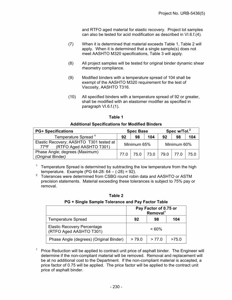
Project No. URB-5436(5)
- 230 -
and RTFO aged material for elastic recovery. Project lot samples can also be tested for acid modification as described in VI.6.f.(4).
(7) When it is determined that material exceeds Table 1, Table 2 will
apply. When it is determined that a single sample(s) does not meet AASHTO M320 specifications, Table 3 will apply.
(8) All project samples will be tested for original binder dynamic shear
rheometry compliance.
(9) Modified binders with a temperature spread of 104 shall be exempt of the AASHTO M320 requirement for the test of Viscosity, AASHTO T316.
(10) All specified binders with a temperature spread of 92 or greater,
shall be modified with an elastomer modifier as specified in paragraph VI.6.f.(1).
Table 1
Additional Specifications for Modified Binders
PG+ Specifications Spec Base Spec w/Tol.2
Temperature Spread 1 92 98 104 92 98 104 Elastic Recovery; AASHTO T301 tested at
77ºF (RTFO Aged AASHTO T301) Minimum 65% Minimum 60%
Phase Angle; degrees (Maximum) (Original Binder)
77.0 75.0 73.0 79.0 77.0 75.0
1 Temperature Spread is determined by subtracting the low temperature from the high
temperature. Example (PG 64-28: 64 – (-28) = 92). 2 Tolerances were determined from CSBG round robin data and AASHTO or ASTM
precision statements. Material exceeding these tolerances is subject to 75% pay or removal.
Table 2
PG + Single Sample Tolerance and Pay Factor Table
Pay Factor of 0.75 or Removal1
Temperature Spread 92 98 104
Elastic Recovery Percentage (RTFO Aged AASHTO T301)
< 60%
Phase Angle (degrees) (Original Binder) > 79.0 > 77.0 >75.0
1 Price Reduction will be applied to contract unit price of asphalt binder. The Engineer will
determine if the non-compliant material will be removed. Removal and replacement will be at no additional cost to the Department. If the non-compliant material is accepted, a price factor of 0.75 will be applied. The price factor will be applied to the contract unit price of asphalt binder.

Project No. URB-5436(5)
- 231 -
Table 3
Single Sample Tolerance and Price Factor Table
Pay Factor of 0.75 or
Removal1
Tests on Original Binder Dynamic Shear, G*/Sin , kPa
< 0.93
Tests on Rolling Thin Film Oven Residue Dynamic Shear, G*/Sin , kPa
< 1.98
Tests on Pressure Aging Vessel Residue Dynamic Shear, G*Sin , kPa
> 5600
Creep Stiffness S, mPa
> 325
m-Value < 0.285
1 Price Reduction will be applied to contract unit price of asphalt binder. The Engineer will
determine if the non-compliant material will be removed. Removal and replacement will be at no additional cost to the Department. If the non-compliant material is accepted, a price factor of 0.75 will be applied. The price factor will be applied to the contract unit price of asphalt binder.
VII. Overall Project Average - Price Reduction Based on Complete M320 Testing
1. Binders that demonstrate acid modification as per VI.6.f.(4) shall be rejected, and the test results will not be included in Overall Project Averages.
2. PG+, Table 1 specifications do not apply to Overall Project Averages.
3. Out of specification material will be determined by the specifications outlined in
AASHTO M320, excluding Direct Tension.
4. The Nebraska Department of Roads, Materials and Research Bituminous Laboratory, will do complete specifications testing on at least one sample per HMA type from the project. The Department will randomly select one sample for complete specifications testing out of every five samples received. When any test result shows a sample not meeting specifications, the previous and following lot sample received will also be tested for complete specifications compliance. Adjacent lot sample testing will continue in this manner until tested samples meet all specifications, or there are no more lot samples to be tested.
5. Samples not selected for complete specifications testing are “control” samples.
Control samples will be tested for original binder AASHTO M320 Dynamic Shear, as well as PG+ phase angle if modified. When a control sample falls out of AASHTO M320 Dynamic Shear and/or PG+ phase angle specification, it will then be tested for complete M320 and PG+ specifications compliance. And, as

Project No. URB-5436(5)
- 232 -
mentioned in VII.4, adjacent lot samples will be tested when any results do not meet specification. Adjacent lot testing will continue until tested samples meet all specifications, or there are no more lot samples to be tested. This additional complete testing for M320 and PG+ compliance is in addition to the minimum number of samples that will be tested for complete M320 and PG+ compliance.
6. At the completion of testing, all M320 test results will be averaged. The average
will not include M320 results from any binder lots that have already been reduced in pay by Table 3. For averages that do not meet M320 specifications, the largest reduction shown in Table 4 will be applied to all the Performance Graded Binder used on the project, with the exception of any binder lots that were already reduced in pay by Tables 2 and/or 3. In cases where there is only one PG Binder Grade lot sample left when determining the Overall Project Average tests results, then the Pay Factor for the PG Binder lot represented by that sample is determined by Table 4.
Table 4
Overall Project Average – Pay Factor Table
Range of Average Pay Factor
Applied
Tests on Original Binder Dynamic Shear, G*/Sin , kPa Min. 1.00 kPa
< 1.00 – 0.98 < 0.98 – 0.96 < 0.96 – 0.94 < 0.94
0.98 0.95 0.92 0.85
Tests on Rolling Thin Film Oven Residue Dynamic Shear, G*/Sin , kPa Min. 2.20 kPa
< 2.20 – 2.156 < 2.156 – 2.09 < 2.09 – 2.024 < 2.024
0.98 0.95 0.92 0.85
Tests Pressure Aging Vessel Residue Dynamic Shear, G*Sin , kPa Max. 5000 kPa
>5000 – 5100 >5100 – 5250 >5250 – 5400 >5400
0.98 0.95 0.92 0.85
m-Value Min. 0.300
< 0.300 – 0.298 < 0.298 – 0.293 < 0.293 – 0.290 < 0.290
0.98 0.95 0.92 0.85
Creep Stiffness S, mPa Max. 300 mPa
>300 – 306 >306 – 315 >315 – 324 >324
0.98 0.95 0.92 0.85
VIII. Single Sample Reduction and Overall Project Average Reduction A sample representing a lot, incurring pay reduction or removal by Table 2 and/or 3, will
incur pay reduction or removal only for the material that the sample represents.

Project No. URB-5436(5)
- 233 -
Only the largest overall project average reduction from Table 4 will apply when more than one test average falls out of AASHTO M320 specifications.
Pay Factors or removals, based on single sample test results, and pay factors based on
overall project average test results, are separate from each other, and both will be applied.
IX. Investigation of Verification Lot Samples That Do Not Meet Specifications When the lot sample shows test results out of specification limits, the process of
resolving the sample failure will include the following actions, as appropriate:
1. The Bituminous Lab may conduct retesting of the remaining portion of the sample as determined necessary to confirm or disaffirm the original test result(s).
2. The Bituminous Laboratory will notify the NDR project personnel, who will in turn
notify the Contractor. All will arrange to investigate all aspects of the testing, loading, handling and delivery of the material in question. The Contractor and NDR project personnel shall report findings to the Bituminous Laboratory.
3. The Bituminous Laboratory will collect and compile all information provided.
4. The Bituminous Laboratory will issue the standard report of tests for all samples tested, to include any resulting pay factor deductions or removals. A copy of the report of tests will be distributed to the District and Construction Division. The District will then provide a copy to the Contractor. Supplier requests for a copy of this report will be directed to the Contractor.
X. Dispute Resolution After testing and investigations have been completed on the sample, and there is still a
dispute, the NDR will select an independent laboratory for referee testing to take place on the remainder of the sample, or any other representative samples obtained. The identity of the independent laboratory will not be revealed until the selected laboratory has completed the referee testing, and the NDR has submitted a final report of the results. If the independent lab's tests indicate failing results and pay deductions equal to or greater than the NDR’s, the Contractor will reimburse the NDR for the cost of testing. If the independent lab's tests indicate that the material meets specification or is at a pay deduction less than the NDR’s, the NDR will assume the cost of testing. When the independent lab's tests indicate a pay deduction, the lesser of the NDR’s and the independent lab's deductions will be applied.
Only the Contractor can initiate dispute resolution, and request referee testing. The
request must be made, in writing, to the NDR Construction Division within 60 days of awareness of sample results. For any period of time past 60 days, dispute resolution is forfeited.

Project No. URB-5436(5)
- 234 -
SECTION 1028 - SUPERPAVE ASPHALTIC CONCRETE (J-7-1013)
Section 1028 in the Standard Specifications is void and superseded by the following: 1028.01 -- Description
1. a. Superpave Asphaltic Concrete is a Contractor-designed mix.
b. The Contractor shall be required to define properties using a gyratory compactor that has met the Superpave evaluation test procedures, during mix design and production.
2. Job Mix Formula
a. Before production of asphaltic concrete, the Contractor shall submit, in writing, a tentative Job Mix Formula (JMF) on the NDOR Mix Design Submittal Form for verification to the Department.
b. The JMF shall be determined from a mix design for each mixture. A volumetric mixture design in accordance with AASHTO R 35 as modified within this specification will be required. However, the mixture for the Superpave specimens and maximum specific gravity mixture shall be aged for two hours at compaction temperature. The mixture shall be prepared using the following:
(1) Mixture Conditioning of Hot Mix Asphalt (HMA), AASHTO R 30.
(2) Method for Preparing and Determining the Density of Hot Mix Asphalt Specimens by Means of the SHRP Gyratory Compactor, AASHTO T312.
c. The JMF shall identify:
(1) The virgin mineral aggregates and pit locations
(2) Recycled Asphalt Pavement (RAP) and source locations
(3) Hydrated lime
(4) Mineral filler
(5) The percent passing value for each specified sieve for the individual and blended materials
d. (1) The Contractor shall submit one uncoated, proportioned 22 lb. (10,000 gram) sample of the blended mineral aggregates for consensus properties and specific gravity testing, for all mix types except SPS. Once verified, the Contractor may begin plant production and QC testing with the QA/QC program.
(2) The Contractor has the option of submitting the following; 2 proportioned 22 lb. (10,000 gram) samples of the blended mineral aggregates (which are precoated with hydrated lime, if lime is used) and two one-quart (liter) samples of the proposed PG Binder to be used in the mixture to the Department Materials and Research Central Laboratory at least 15 NDR working days before production of asphaltic concrete. If submitted these

Project No. URB-5436(5)
- 235 -
samples will be used to verify the Contractor’s Superpave mix design test results and mix properties.
(3) Submitted with these samples shall be a copy of the Contractor’s results for all Superpave mix design tests.
(4) Mix design shall include at a minimum:
(i) The bulk specific gravity (Gsb), which shall be 2.585, for data purposes and as information only, for all mixes.
(ii) The target binder content. The binder content will be determined by ignition oven results. A correction factor of 0.3% will be added to the ignition oven results for mixes containing hydrated lime, and an adjustment factor of 0.1% will be added to the ignition oven results for mixes containing WMA.
(iii) The supplier and grade of PG Binder.
(iv) The maximum specific gravity of the combined mixture (Rice).
(v) The bulk specific gravity (Gmb) and air voids at N initial (Nini), N design (Ndes) and N maximum (Nmax) of the gyratory compacted specimens.
(vi) Voids in the Mineral Aggregate (VMA) and Voids Filled with Asphalt (VFA) at Ndes.
(vii) Fine Aggregate Angularity (FAA) and specific gravity, Coarse Aggregate Angularity (CAA), Flat and Elongated Particles and Sand Equivalent of the aggregate blend.
(viii) Location description and/or legal descriptions and producers of materials used in the mix.
(ix) Dust to Binder Ratio.
(x) JMF compaction temperatures from NDOR Gyratory Temperature Table (See Table 1028.11).
(xi) The hydrated lime content.
3. Quality Control Program:
a. The Contractor shall establish, provide, and maintain an effective Quality Control (QC) Program. The QC Program shall detail the methods and procedures that will be taken to assure that all materials and completed construction conforms to all contract requirements.
b. Although guidelines are established and certain minimum requirements are specified herein and elsewhere in the contract, the Contractor shall assume full responsibility for placing a pavement course that meets the target field values.
c. The Contractor shall establish a necessary level of control that will:
(1) Adequately provide for the production of acceptable quality materials.

Project No. URB-5436(5)
- 236 -
(2) Provide sufficient information to assure both the Contractor and the Engineer that the specification requirements can be met.
d. (1) The Contractor shall develop and submit a copy of their QC Program to the Department. A copy of the QC Program shall be kept on file in the QC lab trailer. This Program shall be updated as needed and submitted annually for review.
(2) The Contractor shall not begin any construction or production of materials without an approved QC Program.
e. The QC Program shall address, as a minimum, the following items:
(1) QC organization chart.
(2) Inspection requirements.
(i) Equipment.
(ii) Asphalt concrete production.
(iii) Asphalt concrete placement.
(3) QC testing plan.
(4) Documentation of QC activities.
(5) Requirements for corrective action when QC or acceptance criteria are not met.
(6) Any additional elements deemed necessary.
(7) A list, with the name and manufacturers model number, for all test equipment used during laboratory testing.
(8) A description of maintenance and calibration procedures, including the frequency that the procedures are performed.
f. The QC organization chart shall consist of the following personnel:
(1) A Program Administrator:
(i) The Program Administrator shall be a full-time employee of the Contractor or a Subcontractor (Consultant) hired by the Contractor.
(ii) The Program Administrator shall have a minimum of 5 years’ experience in highway construction.
(iii) The Program Administrator need not be on the job site at all times but shall have full authority to institute any and all actions necessary for the successful implementation of the QC Program.
(iv) The Program Administrator's qualifications and training shall be described in the QC Program.
(2) Quality Control Technicians:
(i) The quality control technicians shall report directly to the Program Administrator and shall perform all sampling and quality control tests as required by the contract.
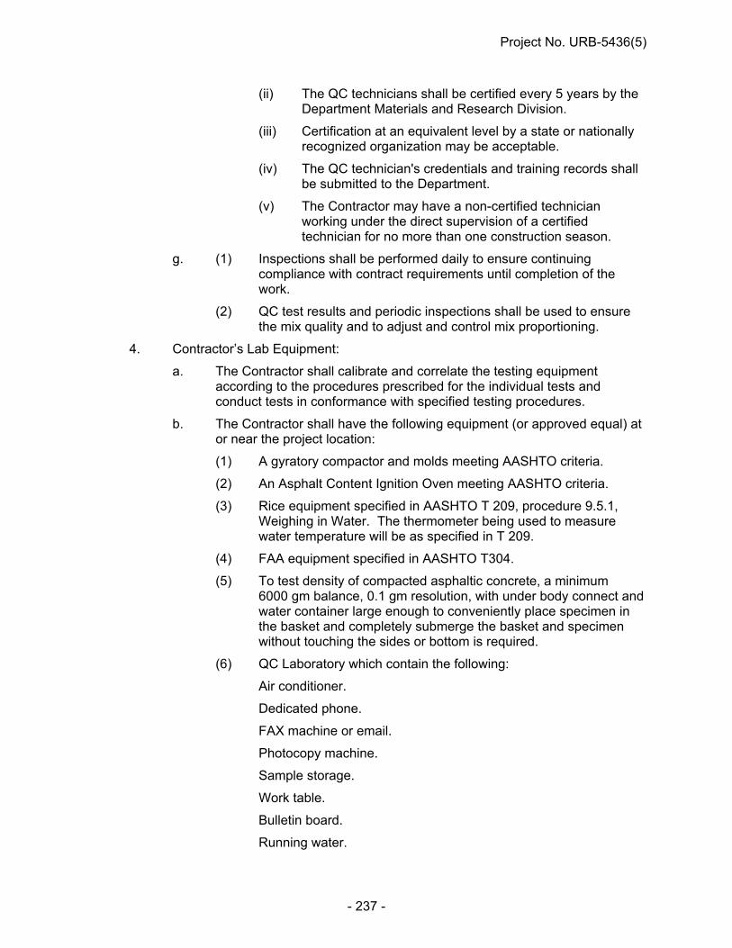
Project No. URB-5436(5)
- 237 -
(ii) The QC technicians shall be certified every 5 years by the Department Materials and Research Division.
(iii) Certification at an equivalent level by a state or nationally recognized organization may be acceptable.
(iv) The QC technician's credentials and training records shall be submitted to the Department.
(v) The Contractor may have a non-certified technician working under the direct supervision of a certified technician for no more than one construction season.
g. (1) Inspections shall be performed daily to ensure continuing compliance with contract requirements until completion of the work.
(2) QC test results and periodic inspections shall be used to ensure the mix quality and to adjust and control mix proportioning.
4. Contractor’s Lab Equipment:
a. The Contractor shall calibrate and correlate the testing equipment according to the procedures prescribed for the individual tests and conduct tests in conformance with specified testing procedures.
b. The Contractor shall have the following equipment (or approved equal) at or near the project location:
(1) A gyratory compactor and molds meeting AASHTO criteria.
(2) An Asphalt Content Ignition Oven meeting AASHTO criteria.
(3) Rice equipment specified in AASHTO T 209, procedure 9.5.1, Weighing in Water. The thermometer being used to measure water temperature will be as specified in T 209.
(4) FAA equipment specified in AASHTO T304.
(5) To test density of compacted asphaltic concrete, a minimum 6000 gm balance, 0.1 gm resolution, with under body connect and water container large enough to conveniently place specimen in the basket and completely submerge the basket and specimen without touching the sides or bottom is required.
(6) QC Laboratory which contain the following:
Air conditioner.
Dedicated phone.
FAX machine or email.
Photocopy machine.
Sample storage.
Work table.
Bulletin board.
Running water.

Project No. URB-5436(5)
- 238 -
Desk and chair.
Separate power supply.
Incidental spoons, trowels, pans, pails.
(7) Diamond saw for cutting cores.
(8) Diamond core drill minimum 3 inch (75 mm).
(9) Oven, 347°F (175°C) minimum, sensitive plus 5F (plus 2C).
(10) USA Standard Series Sieves for coarse and fine aggregate with appropriate shakers (12 inch (300 mm) recommended).
(11) Personal Computer capable of running the latest version of Department Superpave software, creating an electronic copy of the data, and printing to a Color Printer.
5. QC Testing Plan:
a. The testing plan shall provide that the samples be collected in accordance with the Department statistically based procedure of random sampling.
b. The Contractor may add any tests necessary to adequately control production.
c. All QC test results shall be reported on the latest version of the Department’s provided Superpave software by the Contractor with a copy provided to the Engineer within 1 week after the tests are complete. Daily review by the Engineer shall be allowed. At the completion of the asphalt production, the Contractor shall submit to the Department a final copy of the Superpave test results on electronic recording media (CD, e-mail, flash drive, etc.).
d. Corrective Action Requirements:
(1) The Contractor shall establish and utilize QC charts for individual QC tests. The requirements for corrective action shall be linked to the control charts.
(2) The Contractor's QC Program shall detail how the results of QC inspections and tests will be used to determine the need for corrective action.
(3) (i) A clear set of rules to determine when a process is out of control and the type of correction to be taken to regain process control will be provided.
(ii) As a minimum, the plan shall address the corrective actions that will be taken when measurements of the following items or conditions relating to the mixture approach the specification limits:
(I) Plant produced mix gradations at laydown (See gradation tolerances).
(II) Binder content.
(III) Air voids.
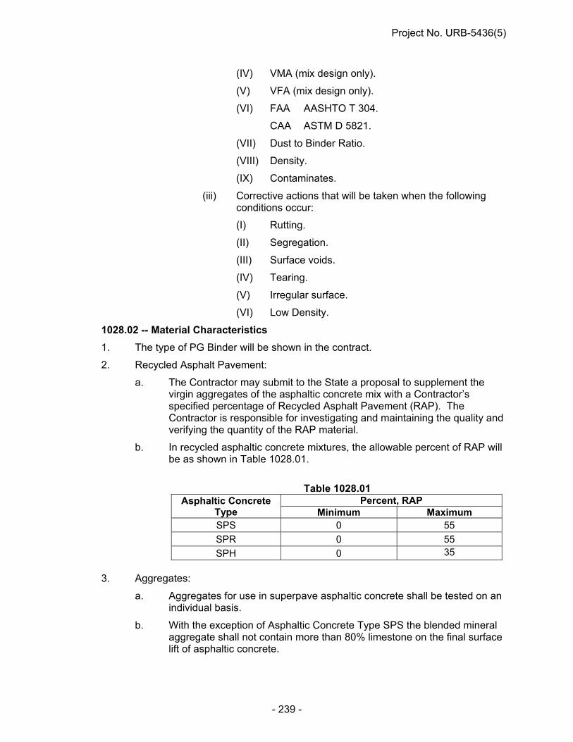
Project No. URB-5436(5)
- 239 -
(IV) VMA (mix design only).
(V) VFA (mix design only).
(VI) FAA AASHTO T 304.
CAA ASTM D 5821.
(VII) Dust to Binder Ratio.
(VIII) Density.
(IX) Contaminates.
(iii) Corrective actions that will be taken when the following conditions occur:
(I) Rutting.
(II) Segregation.
(III) Surface voids.
(IV) Tearing.
(V) Irregular surface.
(VI) Low Density.
1028.02 -- Material Characteristics
1. The type of PG Binder will be shown in the contract.
2. Recycled Asphalt Pavement:
a. The Contractor may submit to the State a proposal to supplement the virgin aggregates of the asphaltic concrete mix with a Contractor’s specified percentage of Recycled Asphalt Pavement (RAP). The Contractor is responsible for investigating and maintaining the quality and verifying the quantity of the RAP material.
b. In recycled asphaltic concrete mixtures, the allowable percent of RAP will be as shown in Table 1028.01.
Table 1028.01
Asphaltic Concrete Type
Percent, RAP Minimum Maximum
SPS 0 55
SPR 0 55
SPH 0 35
3. Aggregates:
a. Aggregates for use in superpave asphaltic concrete shall be tested on an individual basis.
b. With the exception of Asphaltic Concrete Type SPS the blended mineral aggregate shall not contain more than 80% limestone on the final surface lift of asphaltic concrete.

Project No. URB-5436(5)
- 240 -
c. Asphaltic Concrete Type SPR may contain a total maximum of 10% of the virgin material that is composed of natural, uncrushed aggregate by manmade methods commonly known as but not limited to: 47B gravel, 2A gravel, gravel surfacing, sluice sand, blow sand, waste sand, fill sand, road gravel, roofing gravel, hot mix sand or gravel, coarse sand, fine sand, plaster sand, masonary sand, pit run sand or gravel. For clarification on any proposed gravel, contact the Department Flexible Pavements Engineer.
d. Chat or coal sand will not be allowed in any mix.
e. Crushed rock material for use in asphaltic concrete, 1/4 inch (6.35 mm) and smaller, screenings and manufactured sand shall have a Sodium Sulfate loss of not more than 12% by mass at the end of 5 cycles. Sampling size and frequency shall adhere to the current Department Materials Sampling Guide.
f. Quartzite and granite shall conform to the requirements of Subsection 1033.02, Paragraph 4, a. (8). Sampling size and frequency shall adhere to the current Department Materials Sampling Guide.
g. Crushed rock (Limestone) and Dolomite shall conform to the requirements of Paragraph 4.a. (4), (5) and (6). of Subsection 1033.02 of the Standard Specifications. Sampling size and frequency shall adhere to the current Department Materials Sampling Guide.
h. Soundness tests shall not be required for fine sand.
i. Once the satisfactory quality of aggregates from a source has been established, sufficient additional soundness tests will be performed to insure the continued satisfactory quality of the material, as determined by the Materials Sampling Guide
j. Aggregate consensus properties may be performed on material prior to the application of hydrated lime.
k. The coarse aggregate angularity value of the blended aggregate material shall meet or exceed the minimum values for the appropriate asphaltic concrete type as shown in Table 1028.02. If the coarse portion of the blend is all ledge rock the CAA tests may be waived.
Table 1028.02
Coarse Aggregate Angularity (ASTM D 5821)
* Denotes two faced crushed requirements
Asphaltic Concrete
Type CAA (minimum)
SPS -- SPR 83 SPH 95/90*

Project No. URB-5436(5)
- 241 -
l. The fine aggregate angularity value of the blended aggregate material shall meet or exceed the minimum values for the appropriate asphaltic concrete type as shown in Table 1028.03.
m. The specific gravity for calculation of the Fine Aggregate Angularity (FAA) shall be determined on a washed combined aggregate sample of the material passing the No. 8 (2.36 mm) sieve and retained on the No. 100 (150 µm) sieve. The Contractor will determine the specific gravity to be used in the calculation of FAA mixture design value(s) and, if verified by the Department Aggregate Laboratory, this same value can be used throughout production. The verification value determined by the Department Aggregate Laboratory will be on a combined aggregate sample supplied by the Contractor that is representative of the material proposed or being used during production. The specific gravity to be used throughout production to calculate FAA values will be the Contractor’s verified value or the Department determined value (whenever verification is not made) and will be noted on the Mix Design. Changes in aggregate percentages during production may require determination of a revised specific gravity for FAA.
Table 1028.03
Fine Aggregate Angularity (AASHTO T304 Method A)
Asphaltic Concrete
Type FAA (minimum)
SPS --
SPR 43.0
SPH 45.0
n. The coarse aggregate shall not contain flat and elongated particles exceeding the maximum value for the appropriate asphaltic concrete type category shown in these provisions according to Table 1028.04.
Table 1028.04
Flat and Elongated Particles* (ASTM D 4791)
Asphaltic Concrete Type Percent, Maximum SPS 25
SPR 10
SPH 10 *Criterion based on a 5:1 maximum to minimum ratio.
o. The sand equivalent of the blended aggregate material from the fine and coarse aggregates shall meet or exceed the minimum values for the appropriate asphaltic concrete type shown in these provisions according to Table 1028.05.

Project No. URB-5436(5)
- 242 -
Table 1028.05 Sand Equivalent Criteria
(AASHTO T 176) Asphaltic Concrete Type Sand Equivalent, Minimum
SPS 30
SPR 45
SPH 45
p. Dust to binder ratio is the ratio of the percentage by weight of aggregate finer than the No. 200 (75 µm) sieve to the asphalt content expressed as a percent by weight of total mix. The dust to binder ratio shall be within 0.70 and 1.70.
q. The blended aggregate shall conform to the gradation requirements
specified in Table 1028.06 and Table 1028.07 for the appropriate nominal size.
Table 1028.06
Gradation Control Points for 0.75 Inch (19 mm) and 0.5 Inch (12.5 mm) Nominal Size
0.75 Inch (19 mm)
Control Points (percent passing)
0.5 Inch (12.5 mm) Control Points
(percent passing) English Sieve (Metric)
Minimum Maximum Minimum Maximum
1 inch (25 mm) 100.0 3/4 inch (19 mm) 90.0 100.0 100.0 1/2 inch (12.5 mm) 90.0 90.0 100.0 3/8 inch (9.5 mm) 90.0 No. 8 (2.36 mm) 23.0 49.0 28.0 58.0 No. 16 (1.18 mm) No. 30 (600 m) No. 50 (300 m) No. 200 (75 m) 2.0 8.0 2.0 10.0

Project No. URB-5436(5)
- 243 -
Table 1028.07 Gradation Control Points for 0.375 Inch (9.5 mm) Nominal Size and SPR
0.375 Inch (9.5 mm)
Control Points (percent passing)
SPR Control Points
(percent passing)
SPR (Fine) Control Points
(percent passing) English Sieve (Metric)
Minimum Maximum Minimum Maximum Minimum Maximum
3/4 inch (19 mm) 98.0 100.0 1/2 inch (12.5 mm) 100.0 3/8 inch (9.5 mm) 90.0 100.0 81.0 89.0 81.0 96.0 No. 4 (4.75 mm) 90.0 No. 8 (2.36 mm) 32.0 67.0 46.0 56.0 46.0 56.0 No. 16 (1.18 mm) No. 30 (600 m) No. 50 (300 m) 12.0 21.0 12.0 21.0 No. 200 (75 m) 2.0 10.0 4.0 9.0 4.0 9.0
r. The combined mineral aggregate for Asphaltic Concrete, Type SPS, shall
be an aggregate or a combination of aggregates, and mineral filler if needed, that conforms to the gradation requirements specified in Table 1028.08.
Table 1028.08 Gradation Control Points for Type SPS
Control Points (percent passing)
English Sieve (Metric)
Minimum Maximum
1 inch (25 mm) 100.0 ¾ inch (19 mm) 94.0 100.0 ½ inch (12.5 mm) 81.0 100.0 No. 4 (4.75 mm) 70.0 90.0 No. 8 (2.36 mm) 42.0 70.0 No. 16 (1.18 mm) 29.0 43.0 No. 30 (600 m) 19.0 34.0 No. 50 (300 m) 11.0 20.0 No. 200 (75 m) 2.0 10.0
s. Mineral filler shall consist of pulverized soil, pulverized crushed rock,
broken stone, gravel, sand-gravel, sand or a mixture of these materials that conforms to the requirements in Table 1028.09.
Table 1028.09
Mineral Filler for Type SPS Min. Max. Total Percent Passing the No. 50 (300 m) Sieve 95 100 Total Percent Passing the No. 200 (75 m) Sieve 80 100 Plasticity Index (material passing the No. 200 (75 m) Sieve, except soil
0 3
Plasticity Index for Soil 0 6

Project No. URB-5436(5)
- 244 -
1028.03 -- Acceptance Requirements
1. Mix Criteria:
a. The target value for the air voids of the SPH Asphaltic Concrete shall be 4% (±1%) at the Ndes number of gyrations. For Type SPS Asphaltic Concrete the air voids at Ndes shall be a minimum of 1.5% with a maximum of 5.0%. For Type SPR Asphaltic Concrete the air voids shall be 3% (±1%) at the Ndes number of gyrations.
b. The design criteria for each mixture shall be determined from Tables 1028.10, 1028.11, and 1028.12.
Table 1028.10
Gyratory Compaction Effort (Average Design High Air Temperature <39 degrees C)
Asphaltic Concrete Type Nini Ndes Nmax SPS 6 40 62
SPR 7 65 100
SPH 8 95 150
Table 1028.11 Gyratory Compaction Temperatures
Mix Type % RAP Compaction Temp °F
SPS 0-25 270 ± 5
26-50 280 ± 5
SPR 0-35 280 ± 5 36-50 290 ± 5
SPH 0-35 300 ± 5
Table 1028.12 Minimum Binder Content
Mix Type (Metric) Minimum Binder Content, Percent
SPS 4.8
SPR 5.0
3/8 inch (9.5 mm) 5.5
1/2 inch (12.5 mm) 5.1
3/4 inch (19 mm) 5.0
c. During production of Lot #1 and randomly selected lots thereafter, the Contractor shall provide to the Department 6 properly prepared gyratory samples for AASHTO T 283 testing for all mixtures except Asphaltic Concrete Type SPS. Superpave mixtures shall contain 1.25% hydrated lime as specified in the Special Provision “Hydrated Lime for Asphaltic

Project No. URB-5436(5)
- 245 -
Mixtures”. Each Superpave mixture shall be tested for moisture sensitivity in accordance with AASHTO T 283. The 6 inch (150 mm) specimens shall be compacted in accordance with AASHTO T 312 to 7% (± 0.5%) air voids at 95 mm in height and evaluated to determine the Tensile Strength Ratio (TSR).
d. During production of Lot #1, the Contractor shall provide to the
Department two 75mm gyratory puck samples at 4.0% voids (± 0.5%) for APA testing for all mixtures except Asphaltic Concrete Type SPS.
2. The Contractor shall make Mix adjustments when:
a. The mix does not meet the current approved JMF or any other requirements of the contract.
b. Surface voids create a surface or texture that does not meet the criteria of Sections 502 and 503 in these Standard Specifications.
c. Rutting occurs.
3. The Contractor shall inform the Engineer when changes in mixture properties or materials used occur for any reason. Changes such as, but not limited to, types or sources of aggregates or changes in grades, sources, properties or modification procedures (if modified) of PG Binders. The Department may require a new job mix formula, mix design and moisture sensitivity test. The new proposed job mix formula shall be in accordance with the requirements as stated above.
4. Mix adjustments at the plant are authorized within the limits shown in
Table 1028.13 as follows:
a. The adjustment must produce a mix with the percent air voids and all other properties as stated in these specifications.
b. All adjustments must be reported to the Engineer.
c. The adjustment values in Table 1028.13 will be the tolerances allowed for adjustments from the Department verified mix design “Combined Gradation” target values which resulted from production or mix design adjustments, but cannot deviate from Superpave gradation criteria. Mix adjustments for individual aggregates, including RAP, greater than 25% of the original verified mix design proportion or greater than 5% change in the original verified mix design percentage, whichever is greater, may require the Contractor to submit a new mix design, as determined by the Engineer. The Contractor is responsible for requesting new mix design targets as they approach these tolerances, failure to do so may result in a suspension of operations until a new mix design is approved.

Project No. URB-5436(5)
- 246 -
Table 1028.13 Aggregate Adjustments
Sieve Size Adjustments 1 inch (25 mm), 3/4 inch (19 mm), 1/2 inch (12.5 mm), 3/8 inch (9.5 mm), No. 4 (4.75 mm)
± 6%
No. 8 (2.36 mm), No. 16 (1.18 mm), No. 30 (600 µm), No. 50 (300 µm)
± 5%
No. 200 (75 µm) ± 2%
5. Sampling and Testing:
a. The Contractor shall take samples at frequencies identified by the Engineer, according to the Department statistically based procedure. The samples shall be approximately 75 lbs (34 kg) and split according to AASHTO T-248 to create a companion sample. This sample splitting can be either at: 1) the sampling location, with the Department taking custody of their sample at that time or 2) after being transported to the test facility in an insulated container, with the Department taking custody of their sample at that time as determined by the Engineer. The details of sampling, location, splitting etc. shall be determined at the pre-construction conference.
b. All samples transported to the test facility and companion samples within the Lot shall be identified by attaching or faxing the lab calculation sheet from the latest version of the superpave software, stored, and retained by the Contractor until the Department has completed the verification testing process. Transporting of all samples will be under the observation of Department.
c. (1) The sample shall be taken from the roadway, behind the paver before compaction or from the windrow. For SPS mixes, the Contractor has the option to obtain the samples directly at the plant.
(2) At least one QC sample shall be tested for every 750 tons (680 Mg) of plant produced mix.
(i) If, at the completion of the project, the final lot consists of less than 3,750 tons (3,400 Mg) of asphaltic concrete, 1 sample for each 750 tons (680 Mg) or fraction thereof, shall be taken and tested.
(3) Additional sampling and testing for the Contractor's information and quality control may be performed at the Contractor's discretion. Any additional testing will not be used in pay factor determination.
(4) (i) When cold feed samples are being taken, the acquisition shall be timed such that the material in the sample represents, as close as possible, the same material in the sample taken behind the paver. If cold feeds are sampled and tested by Contractor, a split of that sample must be submitted with the hot mix sublot sample. The Contractor will be notified what sublot (a minimum of 1 sublot per lot) sample must be tested for FAA and CAA from the blended

Project No. URB-5436(5)
- 247 -
cold feed material according to the Department random sampling schedule. All other FAA and CAA sublot samples may be taken from the randomly selected portion of the blended cold feed material or obtained from the random samples taken behind the paver. Samples shall be taken under the observation of Department and split according to AASHTO T-248, with the Department taking custody of their sample at that time.
(ii) For projects using RAP material the FAA shall be established as follows: a RAP sample will be processed through an ignition oven and then combined with the proportioned amount of virgin aggregate defined by the mix design and then proceeding with FAA and CAA testing.
d. The sample shall be compacted immediately while still hot (additional heating may be required to raise the temperature of the sample to compaction temperature).
e. Each production sample shall be tested as follows:
(1) Bulk Specific Gravity (Gmb) shall be determined for each specimen in accordance with AASHTO T 166 Bulk Specific Gravity of Compacted Bituminous Mixtures Using Saturated Surface Dry Specimens. One specimen shall be compacted for each production sample.
(2) One Theoretical Maximum Specific Gravity (Gmm) test for each production sample of uncompacted mixture shall be determined in accordance with AASTHO T 209 procedure 9.5.1. Weight in water - Maximum Specific Gravity of Bituminous Paving Mixtures.
(3) (i) The Blended Aggregate Bulk Specific Gravity (Gsb) shall be 2.585 for information only for all mixes.
(ii) FAA - AASHTO T 304 Method A. The pour time of the test sample into the funnel shall be completed in 5±1 seconds.
(iii) CAA - ASTM 5821. For SPR mixes, CAA testing and results are only required on the cold feed verification test for the lot.
(4) The laboratory air voids shall be determined in accordance with the following:
Table 1028.14 Gmb(corr)@Nany = Gmb(meas)@Nmax x ( height@Nmax height@Nany) %Gmm(corr)@Nany = 100 x ( Gmb(corr)@Nany Gmm(meas)) % Air Voids@Nany = 100 - %Gmm(corr)@Nany VMA@Ndes = 100 – (Gmb(corr)@Ndes x Ps Gsb) VFA@Ndes = 100 x ((VMA@Ndes - % Air Voids@Ndes) VMA@Ndes) Measured = (meas) Corrected = (corr)
(5) (i) The percent of PG Binder shall be determined for each QC
test. The percent of PG Binder will be computed by ignition oven results. A correction factor of 0.3% will be

Project No. URB-5436(5)
- 248 -
added to the ignition oven results for mixes containing hydrated lime.
(ii) The gradations shall be determined for each QC test using AASHTO T 30.
(6) Except as noted in this Subsection, all sampling and testing shall be done as prescribed in the Department Materials Sampling Guide and Standard Method of Tests.
f. Testing Documentation:
(1) All test results and calculations shall be recorded and documented on data sheets using the latest version of Department provided “Superpave” software. A copy containing complete project documentation will be provided to the Department at the completion of asphalt production.
g. Superpave Software:
(1) QC charts from the software shall be made available for review by the Engineer at any time.
(2) As a minimum, the following values shall be reported on Department provided software:
(i) Laboratory Gyratory density.
(ii) Ignition oven or cold feed aggregate gradations for all Superpave sieves will be reported.
(iii) PG Binder content shall be plotted to the nearest 0.01% by ignition oven results in accordance with AASHTO T 308.
(iv) The theoretical maximum specific gravity (Rice) to the nearest 0.001% will be reported.
(v) Laboratory Gyratory air voids at Ndes shall be plotted to nearest 0.1%. Laboratory Gyratory air voids, at Nini, Ndes and Nmax shall be reported to nearest 0.1%.
(vi) FAA and CAA of the asphaltic concrete for both cold feed and ignition oven samples will be reported to the nearest 0.1% for FAA and 1% for CAA. A minimum of one sublot FAA and CAA cold feed sample per lot will be tested and recorded on Department provided software.
(vii) VMA content shall be plotted to nearest 0.1% and VFA shall be reported to the nearest 0.1%.
(viii) Dust to Binder ratio to the nearest 0.01 will be reported.
6. Verification Sampling and Testing:
a. The Department will select and test at random one of the sublot samples (750 tons, 680 Mg) within a Lot (3750 tons, 3400 Mg) for verification and report results.

Project No. URB-5436(5)
- 249 -
b. The results of Contractor QC testing will be verified by the Department’s verification tests. Any samples outside of the tolerances in Table 1028.15 and 1028.16 will result in an Independent Assurance (IA) review of testing and may result in the Department test results being applied.
(1) On any given Lot, if the results of Air Void verification testing and its companion QC testing are within 1.0% air voids, the Air Void verification for the entire Lot is complete and the Contractor test results will be used to determine the pay factors. If the Air Void verification test results and the companion QC test results are outside the above tolerance, the results from the verification test will be used to determine the pay factor for that sublot. Any or all of the remaining four Department sublot samples may be tested and the Department sublot test results may be applied to the respective sublots and the resulting pay factors will apply.
(2) On any given Lot, if the results of the FAA verification testing and its companion QC testing are within 0.5 percent, the FAA verification for the entire Lot is complete and the Contractor test results will be used to determine the pay factor. If the FAA verification test results and the companion QC test results are outside the above tolerance, the results from the verification test will be used to determine the pay factor for that sublot. Any or all of the remaining four Department sublot samples may be tested and the Department sublot test results may be applied to the respective sublots and the resulting pay factors will apply.
c. When verification tests are within testing tolerance but results show a consistent pattern of deviation from the QC results, the Engineer may cease production and/or request additional verification testing or initiate a complete IA review.
Table 1028.15 Asphaltic Concrete Testing Tolerances
Test Tolerance Asphalt Content by Ignition Oven 0.5% Gyratory Density 0.020 Maximum Specific Gravity 0.015 Bulk Dry Specific Gravity (Gsb) 0.020 FAA 0.5% CAA 10% Field Core Density 0.020 Air Voids 1.0%
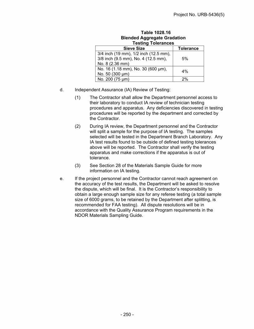
Project No. URB-5436(5)
- 250 -
Table 1028.16 Blended Aggregate Gradation
Testing Tolerances Sieve Size Tolerance
3/4 inch (19 mm), 1/2 inch (12.5 mm), 3/8 inch (9.5 mm), No. 4 (12.5 mm), No. 8 (2.36 mm)
5%
No. 16 (1.18 mm), No. 30 (600 µm), No. 50 (300 µm)
4%
No. 200 (75 µm) 2% d. Independent Assurance (IA) Review of Testing:
(1) The Contractor shall allow the Department personnel access to their laboratory to conduct IA review of technician testing procedures and apparatus. Any deficiencies discovered in testing procedures will be reported by the department and corrected by the Contractor.
(2) During IA review, the Department personnel and the Contractor will split a sample for the purpose of IA testing. The samples selected will be tested in the Department Branch Laboratory. Any IA test results found to be outside of defined testing tolerances above will be reported. The Contractor shall verify the testing apparatus and make corrections if the apparatus is out of tolerance.
(3) See Section 28 of the Materials Sample Guide for more information on IA testing.
e. If the project personnel and the Contractor cannot reach agreement on the accuracy of the test results, the Department will be asked to resolve the dispute, which will be final. It is the Contractor’s responsibility to obtain a large enough sample size for any referee testing (a total sample size of 6000 grams, to be retained by the Department after splitting, is recommended for FAA testing). All dispute resolutions will be in accordance with the Quality Assurance Program requirements in the NDOR Materials Sampling Guide.
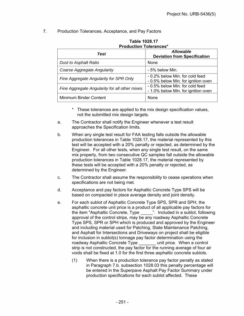
Project No. URB-5436(5)
- 251 -
7. Production Tolerances, Acceptance, and Pay Factors
Table 1028.17 Production Tolerances*
Test Allowable
Deviation from Specification
Dust to Asphalt Ratio None
Coarse Aggregate Angularity - 5% below Min.
Fine Aggregate Angularity for SPR Only - 0.2% below Min. for cold feed - 0.5% below Min. for ignition oven
Fine Aggregate Angularity for all other mixes - 0.5% below Min. for cold feed - 1.0% below Min. for ignition oven
Minimum Binder Content None
* These tolerances are applied to the mix design specification values,
not the submitted mix design targets.
a. The Contractor shall notify the Engineer whenever a test result approaches the Specification limits.
b. When any single test result for FAA testing falls outside the allowable production tolerances in Table 1028.17, the material represented by this test will be accepted with a 20% penalty or rejected, as determined by the Engineer. For all other tests, when any single test result, on the same mix property, from two consecutive QC samples fall outside the allowable production tolerances in Table 1028.17, the material represented by these tests will be accepted with a 20% penalty or rejected, as determined by the Engineer.
c. The Contractor shall assume the responsibility to cease operations when specifications are not being met.
d. Acceptance and pay factors for Asphaltic Concrete Type SPS will be based on compacted in place average density and joint density.
e. For each sublot of Asphaltic Concrete Type SPS, SPR and SPH, the asphaltic concrete unit price is a product of all applicable pay factors for the item "Asphaltic Concrete, Type _____”. Included in a sublot, following approval of the control strips, may be any roadway Asphaltic Concrete Type SPS, SPR or SPH which is produced and approved by the Engineer and including material used for Patching, State Maintenance Patching, and Asphalt for Intersections and Driveways on project shall be eligible for inclusion in sublot(s) tonnage pay factor determination using the roadway Asphaltic Concrete Type _______ unit price. When a control strip is not constructed, the pay factor for the running average of four air voids shall be fixed at 1.0 for the first three asphaltic concrete sublots.
(1) When there is a production tolerance pay factor penalty as stated in Paragraph 7.b. subsection 1028.03 this penalty percentage will be entered in the Superpave Asphalt Pay Factor Summary under production specifications for each sublot affected. These

Project No. URB-5436(5)
- 252 -
individual pay factors will then be multiplied by each other to determine a total pay factor for each sublot [(750 tons) (680 Mg)].
f. The pay factors for the single test air voids and moving average of four air voids pay factors will be determined in accordance with Table 1028.18.
Table 1028.18 Acceptance Schedule
Air Voids - Ndes
Air voids test results for Asphaltic Concrete
Type SPR
Air voids test results for SPH Asphaltic
Concrete
Pay Factor
Moving average of
four Single test
Less than 0.5% Less than 1.5% 50% or Reject 50% or Reject 0.5% to 0.9% 1.5% to 1.9% 50% or Reject 50% 1.0% to 1.4% 2.0% to 2.4% 50% or Reject 95% 1.5% to 1.9% 2.5% to 2.9% 90% 95% 2.0% to 2.4% 3.0% to 3.4% 100% 100% 2.5% to 3.5% 3.5% to 4.5% 102% 104% 3.6% to 4.0% 4.6% to 5.0% 100% 100% 4.1% to 4.5% 5.1% to 5.5% 95% 95% 4.6% to 5.0% 5.6% to 6.0% 90% 95% 5.1% to 5.5% 6.1% to 6.5% 50% or Reject 90% 5.6% to 6.0% 6.6% to 7.0% 50% or Reject 50% 6.1% and over 7.1% and over 50% or Reject 50% or Reject
8. Asphalt Concrete Density Samples:
a. The Contractor shall perform density tests under direct observation of Department personnel. The Contractor shall establish the method of testing in the preconstruction conference and shall test in accordance with the AASHTO T 166, NDR T 587, or as otherwise described in these Special Provisions. The Contractor shall insure that the proper adjustment bias and/or correction factors are used and accessible to Department personnel along with all other inputs when NDR T 587 is selected. All correlation factors and test results shall be generated and reported on the Department Density spreadsheet. When AASHTO T 166 is being used, the Department will observe the Contractor taking, transporting, and testing the cores. The Department will take immediate custody of the cores at the completion of the testing. All disputed values determined using NDR T 587 will be resolved using AASHTO T 166.

Project No. URB-5436(5)
- 253 -
b. The Contractor shall determine the density of samples by comparing the specific gravity of the core sample to the Maximum Specific Gravity (Rice) as follows:
% Density = Specific Gravity of Core Maximum Mix Specific Gravity Rice)
X 100
where:
Sp. Gr. of Core = Wt. of Core in Air Wt. of SSD Core – Wt. of Core in Water
Maximum Mix
Specific Gravity = (Rice)
Wt. of Mix in Air
Wt. of Mix in Air - Wt. of Mix in Water
Note: The individual QC test value of the Maximum Mix Specific Gravity (Rice), determined by AASHTO T 209, will be used to calculate the density of each corresponding core.
c. The Contractor shall cut cores the first day of work following placement of the mixture. The core samples shall be a minimum of a 3 inch (75mm) diameter.
d. Normally, 1 sample for determination of density will be taken from each sublot (750 tons) (680 Mg) at locations determined by the Engineer.
e. The average density of the lot shall be used to compute the pay factor for density. Exceptions to the sampling and testing of core samples for the determination of density are as follows:
(1) When the nominal layer thickness is 1 inch (25 mm) or less, the sampling and testing of density for this layer will be waived.
(2) When the average thickness of the 5 cores for a lot is 1 inch (25 mm) or less, the testing of density samples for this lot will be waived.
(3) When the nominal layer thickness and the average of the original 5 cores for a lot are both more than 1 inch (25 mm), but some of the cores are less than 1 inch (25 mm) thick, additional cores shall be cut at randomly selected locations to provide 5 samples of more than 1 inch (25 mm) thickness for the determination of the pay factor for density.
f. (1) If, at the completion of the project, the final lot consists of less than 3,750 tons (3400 Mg) of asphaltic concrete, a minimum of 3 samples, or 1 sample for each 750 tons (680 Mg) or fraction thereof, whichever is greater, shall be taken and tested for density.
(2) The test results shall be averaged and the density pay factor based on the values shown in Table 1028.19.
(3) Should the average of less than 5 density tests indicate a pay factor less than 1.00, additional density samples to complete the set of five shall be taken at randomly selected locations and the density pay factor based on the average of the 5 tests.

Project No. URB-5436(5)
- 254 -
Table 1028.19 Acceptance Schedule
Density of Compacted Asphaltic Concrete Average Density
(5 Samples, Percent of Voidless Density)
Pay Factor Greater than 92.4 1.00
Greater than 91.9 to 92.4 0.95
Greater than 91.4 to 91.9 0.90
Greater than 90.9 to 91.4 0.85
Greater than 90.4 to 90.9 0.80
Greater than 89.9 to 90.4 0.70 89.9 or Less 0.40 or Reject
g. If requested by the Contractor, check tests for all density tests in the
original set, taken no later than the working day following the receipt of all test results for the lot, will be allowed in lots with a density pay factor of less than 1.00. No re-rolling will be allowed in these lots. Locations for checks tests will be provided by the Engineer from the Random Sampling Schedule. The average density obtained by the check tests shall be used to establish the density pay factor for the lot.
h. The location of density samples are identified by the Random Sampling Schedule. When the random location is noted as zero or the lane width (i.e., zero or 12 ft. on a 12-foot lane), the core shall be cut with the outer edge of the core barrel no greater than 4 inches away (laterally) from the edge of the top of the mat for an unconfined edge or from the edge of the top of the hot mat (joint) for a confined edge. If using a nuclear gauge, the 4 inches would be measured to the edge of the gauge base. The percent density value at these edge-of-lane locations shall be adjusted upward by 2.5%, but to a value of no greater than 92.5%, and the resultant value used in determining the density pay factor. No initial value of 92.5 or greater shall be adjusted.
WARM MIX ASPHALT (J-7-0714)
The Contractor has the option to use Warm Mix Asphalt (WMA) meeting the following requirements. 1. Warm Mix Asphalt (WMA) Warm Mix Asphalt mixtures shall follow the requirements of Superpave Asphaltic
Concrete and all other applicable sections with the following exceptions: a. The Contractor shall request the use of a WMA additive in writing when
submitting the Job Mix Formula. The requested additive shall be an approved Level I or II production product or combination thereof. The manufacturer’s

Project No. URB-5436(5)
- 255 -
recommended additive rates, specifications, and all other pertinent information shall be included in the requests. All requests must be approved by the Flexible Pavements Engineer prior to their use.
b. Level I Production (1) Level I WMA additives are as follows: water injection devices. (2) Hydrated Lime at 1.25% by weight of virgin aggregate is required for all
mixtures. (3) The allowable drop in temperature shall be a maximum of 40°F below the
producer’s recommended production temperature for Hot Mix Asphalt (HMA), or less as required during production to achieve proper laydown and compaction properties. Plant production temperatures shall not drop below 230°F.
c. Level II Production (1) Level II WMA additives are as follows: Advera, Evotherm (DAT, ET, 3G),
AkzoNobel Rediset LQ-1102C, and Sasobit. (2) For amine based WMA additives, 25% of the additive must be considered
an amine based anti-stripping agent. Amine based WMA additives with anti-stripping agents shall be terminal blended by the binder supplier or a system approved by the Flexible Pavements Engineer for application at the plant. For all other warm mix technologies hydrated lime shall be added at a minimum rate of 1.25% by weight of virgin aggregate, including the weight of limestone. Hydrated Lime shall not be used on Level II WMA mixtures when the WMA additive is an Amine based additive or when the Amine WMA additives are used in combination with Level I water injection. The minimum rate for amine based WMA additives shall be 0.7%. The dosage rate of anti-strip shall not exceed manufacturer’s recommendations.
(3) The drop in temperature shall be a maximum of 90°F from the producer’s
recommended production temperature for HMA. Plant production temperatures shall not drop below 215°F.
d. Other WMA additives shall not be used unless otherwise approved by the
Flexible Pavements Engineer. e. WMA additives may be used in combination by approval of the Flexible
Pavements Engineer. f. Asphalt mixes shall be tested for TSR on the first lot of production and then on
randomly selected lots thereafter. g. Field samples shall be heated and compacted using the following table unless
otherwise approved by the Flexible Pavements Engineer.

Project No. URB-5436(5)
- 256 -
Gyratory Compaction Temperatures Mix Type % Rap Compaction Temp °F SPS 0-25 270 + 5 26-50 280 + 5 SPR 0-35 280 + 5 36-50 290 + 5 SPH 0-35 300 + 5
h. NDOR may suspend or eliminate the use of WMA on a project if any of the
following conditions occur: rutting, segregation, surface voids, tearing, irregular surface, low density, raveling, stripping, or if pavement does not meet any other design criteria.
2. Warm Mix Asphalt (WMA) additives will be measured and paid for directly by the unit of
each for the item “Hydrated Lime/Warm Mix Asphalt” for each ton of hot mix asphalt produced.
ASPHALT DENSITY GAUGE (J-7-1013)
Description An Asphalt Density Gauge may be used for Quality Control when determining the in-place density of asphaltic concrete. Material Requirements The device must be approved by the Flexible Pavements Engineer. Testing Method 1. The Contractor shall establish the method of testing in the preconstruction conference.
All testing shall be in accordance with AASHTO T-343 and as directed in this provision. 2. The first 3 density locations of the project shall be cored in accordance with
AASHTO T166 to calibrate the asphalt density gauge. Prior to coring, the Contractor shall calibrate the device at each core location.
3. Calibration: A correction factor shall be established for the first 3 cores by calculating
the difference between the average density measurement of the asphalt density gauge and the roadway core density. This correction factor shall be entered into the device and used for measuring subsequent densities. The correction factor shall be verified with another core for every 15 density readings that are to be recorded.
4. Density Reading Procedure: Place the asphalt density gauge on the asphalt mat over
the area to be tested. Record the density reading, and repeat this process for a total of 5 readings, as detailed in Figure 1. An average of the 5 readings will be used as the density reading for each location. For densities taken less than 6 inches from the edge of the lift, density readings shall be taken as shown in Figure 2. The span between density reading locations in each direction shall be no greater than 12”.

Project No. URB-5436(5)
- 257 -
5. If any density measured by the asphalt density gauge is below 90%, a density core shall
be cut at that location and used for density measurement for that sublot. Density readings below 90% shall not be used to calculate a correction factor. All disputed values determined using the asphalt density gauge will be resolved using AASHTO T 166.
ASPHALTIC CONCRETE LONGITUDINAL JOINT DENSITY TESTING (J-7-1013)
Description One sample for determination of joint density will be taken randomly from each lot. This joint density sample stands independent of the required standard density per sublot used for determining the average of 5 density pay factor. Equipment Testing shall be conducted in accordance with the AASHTO T 166, NDR T 587, or an approved Asphalt Density Gauge. The Contractor shall insure that the proper adjustment bias and/or correction factors are used and accessible to Department personnel, along with all other inputs
1
2
3 4
5
= Density Gauge Reading Location
Figure 1: Asphalt density gauge reading pattern
= Location of Core
12” max
= Density Gauge Reading Location
0”, 1”, or 4” from mat edge - as detailed in the provisions and by the
Figure 2: Asphalt density gauge reading pattern less than 6” from mat edge
1 2 3 4 5

Project No. URB-5436(5)
- 258 -
when NDR T 587 or the Asphalt Density Gauge is selected. All correlation factors and test results shall be generated and reported on the Department Density spreadsheets. Testing 1. The Contractor shall establish the method of testing in the preconstruction conference. 2. One sample for determination of joint density will be taken randomly from each lot, as
determined by the Engineer. The location of the edge density samples are identified by the Random Sampling Schedule.
3. The joint density core shall be cut 1 inch away (laterally) from the identified edge of the
top of the mat. 4. The Contractor shall cut cores the first day of work following placement of the mixture.
The core samples shall be a minimum of a 3 inch (75mm) diameter. 5. The Department will observe the Contractor taking, transporting, and testing the cores
(as applicable). The Department will take immediate custody of the cores at the completion of the testing. All disputed values determined using NDR T 587 or the Asphalt Density Gauge will be resolved using AASHTO T166.
6. The Contractor shall determine the density of samples by comparing the specific gravity
of the core sample to the Maximum Specific Gravity (Rice) as follows:
% Density = Specific Gravity of Core Maximum Mix Specific Gravity Rice)
X 100
where:
Sp. Gr. of Core = Wt. of Core in Air Wt. of SSD Core – Wt. of Core in Water
Maximum Mix Specific Gravity = (Rice)
Wt. of Mix in Air Wt. of Mix in Air - Wt. of Mix in Water
Note: The individual QC test value of the Maximum Mix Specific Gravity (Rice), determined by AASHTO T 209, will be used to calculate the density of each corresponding core.
7. Exceptions to the sampling and testing of joint density core samples for the
determination of density are as follows:
a. When the nominal layer thickness is 1 inch (25 mm) or less, the sampling and testing of density for this layer will be waived.
b. When the average thickness for the standard lot is 1 inch (25 mm) or less, the testing of joint density samples for this lot will be waived.
8. If requested by the Contractor, a re-test for the original joint density test, taken no later
than the working day following the receipt of the test result, will be allowed. Locations of re-tests will be provided by the Engineer from the Random Sampling Schedule. The density obtained by the re-test shall be used to establish the density pay factor for the lot.

Project No. URB-5436(5)
- 259 -
Method of Measurement
All work related to the Asphaltic Concrete Longitudinal Joint Density Sample will not be measured and paid for but will be subsidiary to the associated asphaltic concrete. Basis of Payment
1. The pay factor shall be computed according to the following table:
Joint Density Test Lot Pay Factor Joint Density SPS SPR SPH 93.0 or greater 102% 102% 102%
92.0 to 92.9 100% 102% 102% 91.0 to 91.9 98% 100% 102% 90.0 to 90.9 98% 98% 100% 89.0 to 89.9 98% 98% 98% 88.9 or Less 98% 98% 98%
2. The pay factor will be incorporated in the production specs calculation in the Superpave
Software. Any incentive or disincentive will be added or subtracted to the pay factor after any other applicable production tolerances pay factors have been incorporated. The pay factor will apply to the entire lot.
HYDRATED LIME FOR ASPHALT MIXTURES
1. General
Hydrated lime will be added to all aggregates (at the Contractor’s option, limestone may be excluded) used for asphalt mixtures except Asphaltic Concrete used for Temporary Surfacing, and Asphaltic Concrete Type SPS, HRB and SPL. Hydrated lime will be added to pre-moistened aggregates whether it is used directly into the mix or stockpiled for marinating purposes. The application of moisture and hydrated lime to the aggregates along with equipment calibration and procedures to prevent any "dusting" shall be documented and approved in the Contractor's Quality Control (QC) Plan.
2. Material Requirements
The lime shall meet the chemical and physical properties defined in AASHTO M 303 for Type I - High calcium-hydrated lime, or meet the requirements of ASTM 1097 for Type S Hydrated Lime.
The hydrated lime being used, whether for mix design or plant mix production, shall be stored in an enclosed container and must be used within 90 days. Stockpiles marinating shall also be used within 90 days. Lime that is stored over 90 days in a protected storage silo environment may be submitted for chemical analysis to verify that it meets the specification for use in the mix.
Water shall conform to the requirements of Section 1005.

Project No. URB-5436(5)
- 260 -
3. Construction
Prior to the addition of hydrated lime the aggregates shall have a minimum moisture content of 3% by weight of aggregate. The surface of the aggregate shall be uniformly dampened by water.
If additional moisture is required it shall be added at the entry end of an enclosed pug mill mixer and prior to the addition of hydrated lime.
Hydrated Lime shall be added at a rate of 1.25 percent by weight of virgin aggregate, including the weight of the limestone.
4. Equipment
The addition of lime shall be plant controlled, and blended with an enclosed twin-shaft pug mill with a production capacity rating that exceeds the aggregate feed rate. It shall be capable of effective mixing in the full range of asphaltic concrete production rates.
The pug mill set up shall be located in the system at a location where the mixed material can be readily inspected on a belt prior to entry into the drum.
The pug mill shall be designed such that the mixture of aggregate and hydrated lime is moved in a near horizontal direction (within 20 degrees of horizontal) by the mixing paddles without the aid of conveyor belts for a distance of at least three feet (900 mm). Mixing devices which permit the mixture of aggregate and hydrated lime to fall through the mixing blades onto a belt or chute are not acceptable.
A positive signal system and a limit switch device shall be installed in the plant at the point of introduction of the hydrated lime. The positive signal system shall be placed between a metering device and the drum plant, and utilized during production whereby an alarm is activated, alerting the plant that the hydrated lime is not being introduced into the mixture.
The hydrated lime storage silo shall have enough capacity for continuous production. The silo shall be replenished by pneumatic delivery from road tankers at a pressure that will not create dusting. Hydrated lime will be dispensed from the silo into the pug mill by a conventional vane feeder or a load cell pod system.
The mechanism for adding moisture to the aggregate will be configured and located to insure that all virgin aggregate is uniformly coated with moisture prior to the lime application.
5. Sampling and Testing
Hydrated lime shall be certified by the supplier stating its compliance to the specifications.
A physical inventory of hydrated lime usage will be required during mix production. A daily silo inventory, noting "beginning weight", "weight added during the day’s production", and “end of day weight”, will be recorded and made available for review by the Engineer. When a weigh pod system is used, an accumulative accounting method shall be used to calculate and review lime addition rates throughout production. When

Project No. URB-5436(5)
- 261 -
calculations indicate a hydrated lime usage of ±0.15 percent from the design percentage the Contractor shall assume the responsibility to cease production and recalibrate the system prior to resuming mix production. Any asphaltic concrete placed having 0.15 percent below the design percentage shall be removed and replaced at no cost.
The percent of moisture shall be determined and documented: 1) from belt samples or 2) from stockpile samples, a minimum of once per day.
6. Mixture QC and Verification Testing
During an ignition oven burn off, lime will combine with the sulfur in the binder and produce ash. Therefore, when mix containing hydrated lime is being designed and produced a correction factor to the ignition oven burn off result of +0.30% shall be used. This correction factor shall be added to the ignition oven binder content reading in order for the actual binder content to be determined.
HYDRATED LIME SLURRY FOR ASPHALT MIXTURES
1. General — The Contractor will have the option of using Hydrated Lime Slurry For Asphalt Mixtures or Hydrated Lime For Asphalt Mixtures. Hydrated lime slurry will be added to all aggregates (at the Contractor’s option, limestone may be excluded) used for asphalt mixtures except Asphaltic Concrete used for Temporary Surfacing, and Asphaltic Concrete Type SPS and SPL. Hydrated lime slurry will be added to aggregates whether it is used directly into the mix or stockpiled for marinating purposes. The application of hydrated lime slurry to the aggregates along with equipment calibration and procedures shall be documented and approved in the Contractor's Quality Control (QC) Plan.
2. Material Requirements — The lime shall meet the chemical and physical properties defined in AASHTO M 303 for Type I - High calcium-hydrated lime, or meet the requirements of ASTM 1097 for Type S Hydrated Lime.
The dry hydrated lime being used, whether for mix design or plant mix production, shall be stored in an enclosed container and must be used within 90 days. Stockpiles marinating shall also be used within 90 days. Hydrated lime (dry or slurry) that is stored over 90 days in a protected storage silo or slurry tank may be submitted for chemical analysis to verify that it meets the specification for use in the mix.
Water shall conform to the requirements of Section 1005.
3. Construction — Hydrated Lime shall be added at a rate of 1.25 percent by weight of virgin aggregate, including the weight of the limestone.
4. Equipment — The addition of lime shall be plant controlled, and blended with an enclosed twin-shaft pug mill with a production capacity rating that exceeds the aggregate feed rate. It shall be capable of effective mixing in the full range of asphaltic concrete production rates.
The pug mill set up shall be located in the system at a location where the mixed material can be readily inspected on a belt prior to entry into the drum.
The pug mill shall be designed such that the mixture of aggregate and hydrated lime is moved in a near horizontal direction (within 20 degrees of horizontal) by the mixing paddles without the aid of conveyor belts for a distance of at least three feet (900 mm).

Project No. URB-5436(5)
- 262 -
Mixing devices which permit the mixture of aggregate and hydrated lime to fall through the mixing blades onto a belt or chute are not acceptable. A positive signal system and a limit switch device shall be installed in the plant at the point of introduction of the hydrated lime. The positive signal system shall be placed between a metering device and the drum plant, and utilized during production whereby an alarm is activated; alerting the plant that the hydrated lime is not being introduced into the mixture. A minimum of two hydrated lime slurry tanks shall be used for blending and supply. Slurry shall be drawn for production from only one tank at a time. The hydrated lime slurry tanks shall have enough capacity for continuous production. Hydrated lime slurry shall be dispensed from a slurry tank into the pug mill by a pressure regulated spray system having an electronic flow measurement system that has been calibrated to insure the proper application rates will be provided. Certificate of Calibration for the spray bar system should be provided by the Contractor with the calibration being performed by a third party every 12 months (minimum) or at the Engineer’s request. The electronic flow measurement system shall automatically record the flow rate of the lime slurry being feed to the pug mill. The data recorder system shall be capable of recording the flow rate (in gallons per minute) at intervals of not more than 5 minutes and shall have the capability of calculating the volume of lime slurry used each day, from each slurry tank, and shall be capable of printing a summary of the daily lime slurry usage for each tank. This printout of the daily lime slurry volumes shall be presented to the NDOR representative at the end of each day’s production.
5. Blending and Supply Hydrated Lime Slurry — The Contractor shall determine the
target hydrated lime slurry concentration (percent solids) that will be used to produce the asphalt mixture. This target concentration value shall be provided to the Engineer prior to production of the asphalt mixture and shall not be less than 30 percent. The target concentration value shall not be modified without the approval of the Engineer. It is the Contractors responsibility to control the concentration of the hydrated lime slurry.
Only valid weights of dry hydrated lime shall be added to the required quantity of water to provide uniform hydrated lime slurry having a dry solids content within ±0.5 percent of the Contractor’s target value. Water or dry hydrated lime shall not be added to a tank that is actively supplying hydrated lime slurry to the pug mill. Hydrated lime slurry shall not be drawn from a tank that is not completely blended in accordance with the manufacturer’s recommendations. The hydrated lime slurry in the active supply tank shall be agitated prior to and during production in accordance with the manufacturer’s recommendations. Dry hydrated lime shall be transferred at a pressure that will not create dusting.
5.1 If individual hydrated lime slurry tanks are dedicated to only blending or supply,
then thoroughly mixed hydrated lime slurry may be added from the blending

Project No. URB-5436(5)
- 263 -
tank(s) to the supply tank during production, provided the concentrations are within ±0.5 percent.
5.2 If the hydrated lime slurry tanks are used for both blending and supply, the tanks shall be plumbed such that hydrated lime slurry can be supplied to the pug mill from any of the blending/supply tanks without disruption of the slurry supply.
6. Sampling and Testing — Hydrated lime shall be certified by the supplier stating its
compliance to the specifications.
The concentration of the lime slurry shall be controlled within ±0.5 percent of the target hydrated lime slurry concentration (percent solids). The concentration of the hydrated lime shall be determined in accordance with section 6.1. It is the Contractor’s responsibility to halt production to make adjustments when the concentrations fall out of compliance. The concentration of the lime slurry shall be determined and recorded by the Contractor immediately following blending each batch of lime slurry for the project. These records shall include date and time of test, sample collection information, and the unit weight, temperature and concentration of slurry. These records shall be made available to the Engineer upon request.
A physical inventory of hydrated lime usage will be required during mix production. This inventory shall be used to verify the lime application rate, and for payment of the hydrated lime. The concentration of the lime slurry shall be determined and recorded by the Contractor at the beginning and at approximately the mid-point of each day’s production. The hydrated lime slurry samples shall be collected from the supply line leading to the pug mill. These records shall include date and time of test, sample collection information, and the unit weight, temperature and concentration of slurry. These records shall be presented to the NDOR representative at the end of each day’s production. When calculations indicate that the application rate of “dry” hydrated lime to the aggregate is ±0.15 percent from the design percentage the Contractor shall assume the responsibility to cease production and recalibrate the system prior to resuming mix production. Any asphaltic concrete placed having a “dry” hydrated lime application rate (applied to aggregate) of 0.15 percent below the design percentage shall be removed and replaced at no cost.
6.1 The Contractor shall determine the solids content (concentration) of the hydrated
lime slurry using Table 1, Table 2 and the Slurry Worksheet. The Contractor shall provide and use the standard weight per 83.205-ml Gardner cup meeting the requirements of ASTM D 244.
After a batch of lime slurry has been produced, use the following procedures to verify that the intended percent solids have been achieved.
1. Fill a quart container 3/4 full with lime slurry. Samples can be taken from
ports located at either end of the vessel. Do not use glass.

Project No. URB-5436(5)
- 264 -
2. Weigh a dry, empty Gardner (WPG) cup and cover to the nearest 0.01 of a gram. Record this weight.
3. Shake the lime slurry sample well. Immediately fill the WPG cup.
4. Tap the WPG cup lightly on an immovable object to allow for the escape of air bubbles.
5. Slowly turn the cap of the WPG cup until it is completely seated. If the cover is pushed on quickly, lime slurry will squirt out through the hole in the center. Be sure to point the top of the WPG away from you (or others) while putting on the cap.
6. Hold the WPG cup by the top and bottom with thumb and forefinger. Be sure to cover the hole in the cap.
7. Rinse the WPG cup under running water to remove any lime from the outside of the cup.
8. Dry the outside of the cup thoroughly.
9. Weigh the dry, filled WPG cup to the nearest 0.01 of a gram. Record this weight.
10. Promptly remove the cover, insert thermometer and record the temperature.
11. Subtract the empty cup weight (from step 2) from the filled cup weight (step 9) and record the difference.
12. Multiply the difference by 0.1. This number is the density (lbs./gallon) of the lime slurry. Record this number.
13. Look up the temperature correction in Table 2 and record the value.
14. Multiply the slurry density times the temperature correction value. This is the adjusted slurry density. Record the adjusted slurry density on the slurry worksheet.
15. Find the nearest density to that recorded above on the “Slurry Solids Chart” on Table 1, Slurry Solids Chart - 24 degrees C. The corresponding number is the percent solids (concentration) of the lime slurry sample. Record on worksheet.
7. Mixture QC and Verification Testing — During an ignition oven burn off, lime will
combine with the sulfur in the binder and produce ash. Therefore, when mix containing hydrated lime is being designed and produced a correction factor to the ignition oven burn off result of +0.30% shall be used. This correction factor shall be added to the ignition oven binder content reading in order for the actual binder content to be determined.

Project No. URB-5436(5)
- 265 -
Table 1, Page 1 Slurry Solids Chart – 24°C
Density lbs./gal.
Slurry Solids
% Density lbs./gal.
Slurry Solids
% Density lbs./gal.
Slurry Solids
% Density lbs./gal.
Slurry Solids
% 9.108 15.1 9.402 20.1 9.715 25.1 10.050 30.1 9.114 15.2 9.406 20.2 9.722 25.2 10.057 30.2 9.120 15.3 9.414 20.3 9.728 25.3 10.064 30.3 9.128 15.4 9.420 20.4 9.735 25.4 10.071 30.4 9.131 15.5 9.426 20.5 9.741 25.5 10.078 30.5 9.137 15.6 9.433 20.6 9.748 25.6 10.085 30.6 9.143 15.7 9.439 20.7 9.755 25.7 10.092 30.7 9.148 15.8 9.445 20.8 9.761 25.8 10.099 30.8 9.154 15.9 9.451 20.9 9.768 25.9 10.106 30.9 9.160 16.0 9.457 21.0 9.774 26.0 10.113 31.0 9.166 16.1 9.463 21.1 9.781 26.1 10.120 31.1 9.171 16.2 9.469 21.2 9.787 26.2 10.127 31.2 9.177 16.3 9.476 21.3 9.794 26.3 10.134 31.3 9.183 16.4 9.482 21.4 9.800 26.4 10.141 31.4 9.189 16.5 9.488 21.5 9.807 26.5 10.148 31.5 9.195 16.6 9.494 21.6 9.814 26.6 10.155 31.6 9.200 16.7 9.500 21.7 9.820 26.7 10.163 31.7 9.206 16.8 9.506 21.8 9.827 26.8 10.170 31.8 9.212 16.9 9.513 21.9 9.833 26.9 10.177 31.9 9.218 17.0 9.519 22.0 9.840 27.0 10.184 32.0 9.224 17.1 9.525 22.1 9.847 27.1 10.191 32.1 9.230 17.2 9.531 22.2 9.853 27.2 10.198 32.2 9.235 17.3 9.538 22.3 9.860 27.3 10.205 32.3 9.241 17.4 9.544 22.4 9.867 27.4 10.212 32.4 9.247 17.5 9.550 22.5 9.873 27.5 10.220 32.5 9.253 17.6 9.556 22.6 9.880 27.6 10.227 32.6 9.259 17.7 9.563 22.7 9.887 27.7 10.234 32.7 9.265 17.8 9.569 22.8 9.894 27.8 10.241 32.8 9.271 17.9 9.575 22.9 9.900 27.9 10.248 32.9 9.277 18.0 9.581 23.0 9.907 28.0 10.255 33.0 9.282 18.1 9.588 23.1 9.914 28.1 10.263 33.1 9.288 18.2 9.594 23.2 9.920 28.2 10.270 33.2 9.294 18.3 9.600 23.3 9.927 28.3 10.277 33.3 9.300 18.4 9.607 23.4 9.934 28.4 10.284 33.4 9.306 18.5 9.613 23.5 9.941 28.5 10.292 33.5 9.312 18.6 9.619 23.6 2.948 28.6 10.299 33.6 9.318 18.7 9.626 23.7 9.954 28.7 10.306 33.7 9.324 18.8 9.632 23.8 9.961 28.8 10.314 33.8 9.330 18.9 9.638 23.9 9.968 28.9 10.321 33.9 9.336 19.0 9.645 24.0 9.975 29.0 10.328 34.0 9.342 19.1 9.651 24.1 9.982 29.1 10.335 34.1 9.348 19.2 9.658 24.2 9.988 29.2 10.343 34.2 9.354 19.3 9.664 24.3 9.995 29.3 10.350 34.3 9.360 19.4 9.670 24.4 10.002 29.4 10.358 34.4 9.366 19.5 9.677 24.5 10.009 29.5 10.365 34.5 9.372 19.6 9.683 24.6 10.016 29.6 10.372 34.6 9.378 19.7 9.690 24.7 10.023 29.7 10.380 34.7 9.384 19.8 9.696 24.8 10.030 29.8 10.387 34.8 9.390 19.9 9.703 24.9 10.037 29.9 10.394 34.9 9.396 20.0 9.709 25.0 10.044 30.0 10.402 35.0

Project No. URB-5436(5)
- 266 -
Table 1, Page 2 Slurry Solids Chart – 24°C
Density lbs./gal.
Slurry Solids
% Density lbs./gal.
Slurry Solids
% Density lbs./gal.
Slurry Solids
% Density lbs./gal.
Slurry Solids
% 10.409 35.1 10.795 40.1 11.210 45.1 11.658 50.1 10.417 35.2 10.803 40.2 11.218 45.2 11.667 50.2 10.424 35.3 10.811 40.3 11.227 45.3 11.677 50.3 10.432 35.4 10.819 40.4 11.236 45.4 11.686 50.4 10.439 35.5 10.827 40.5 11.244 45.5 11.695 50.5 10.447 35.6 10.835 40.6 11.253 45.6 11.705 50.6 10.454 35.7 10.843 40.7 11.262 45.7 11.714 50.7 10.462 35.8 10.851 40.8 11.270 45.8 11.724 50.8 10.469 35.9 10.859 40.9 11.279 45.9 11.733 50.9 10.477 36.0 10.867 41.0 11.288 46.0 11.743 51.0 10.484 36.1 10.875 41.1 11.297 46.1 11.752 51.1 10.492 36.2 10.883 41.2 11.305 46.2 11.762 51.2 10.499 36.3 10.892 41.3 11.314 46.3 11.771 51.3 10.507 36.4 10.900 41.4 11.323 46.4 11.781 51.4 10.514 36.5 10.908 41.5 11.332 46.5 11.790 51.5 10.522 36.6 10.916 41.6 11.341 46.6 11.800 51.6 10.530 36.7 10.924 41.7 11.349 46.7 11.809 51.7 10.537 36.8 10.932 41.8 11.358 46.8 11.819 51.8 10.545 36.9 10.941 41.9 11.367 46.9 11.828 51.9 10.552 37.0 10.949 42.0 11.376 47.0 11.838 52.0 10.560 37.1 10.957 42.1 11.385 47.1 11.848 52.1 10.568 37.2 10.965 42.2 11.394 47.2 11.857 52.2 10.575 37.3 10.974 42.3 11.403 47.3 11.867 52.3 10.583 37.4 10.982 42.4 11.412 47.4 11.877 52.4 10.591 37.5 10.990 42.5 11.421 47.5 11.886 52.5 10.599 37.6 10.998 42.6 11.430 47.6 11.896 52.6 10.606 37.7 11.007 42.7 11.439 47.7 11.906 52.7 10.614 37.8 11.015 42.8 11.447 47.8 11.915 52.8 10.622 37.9 11.023 42.9 11.456 47.9 11.925 52.9 10.629 38.0 11.032 43.0 11.465 48.0 11.935 53.0 10.637 38.1 11.040 43.1 11.475 48.1 11.945 53.1 10.645 38.2 11.048 43.2 11.484 48.2 11.954 53.2 10.653 38.3 11.057 43.3 11.493 48.3 11.964 53.3 10.661 38.4 11.065 43.4 11.502 48.4 11.974 53.4 10.668 38.5 11.074 43.5 11.511 48.5 11.984 53.5 10.676 38.6 11.082 43.6 11.520 48.6 11.994 53.6 10.684 38.7 11.090 43.7 11.529 48.7 12.004 53.7 10.692 38.8 11.099 43.8 11.538 48.8 12.014 53.8 10.700 38.9 11.107 43.9 11.547 48.9 12.023 53.9 10.707 39.0 11.116 44.0 11.556 49.0 12.033 54.0 10.715 39.1 11.124 44.1 11.566 49.1 12.043 54.1 10.723 39.2 11.133 44.2 11.575 49.2 12.053 54.2 10.731 39.3 11.141 44.3 11.584 49.3 12.063 54.3 10.739 39.4 11.150 44.4 11.593 49.4 12.073 54.4 10.747 39.5 11.158 44.5 11.602 49.5 12.083 54.5 10.755 39.6 11.167 44.6 11.612 49.6 12.093 54.6 10.763 39.7 11.175 44.7 11.621 49.7 12.103 54.7 10.771 39.8 11.184 44.8 11.630 49.8 12.113 54.8 10.779 39.9 11.193 44.9 11.639 49.9 12.123 54.9 10.787 40.0 11.201 45.0 11.649 50.0 12.134 55.0

Project No. URB-5436(5)
- 267 -
Table 2 Correction Factor to Adjust Slurry Densities for Temperature
Temp (C) Factor Temp (C) Factor 20 0.99927 61 1.01176 21 0.99944 62 1.01218 22 0.99962 63 1.01262 23 0.99981 64 1.01305 24 1.00000 65 1.01349 25 1.00002 66 1.01394 26 1.00041 67 1.01439 27 1.00063 68 1.01485 28 1.00085 69 1.01531 29 1.00109 70 1.01578 30 1.00132 71 1.01626 31 1.00157 72 1.01673 32 1.00182 73 1.01722 33 1.00208 74 1.01770 34 1.00234 75 1.01820 35 1.00261 76 1.01870 36 1.00289 77 1.01920 37 1.00318 78 1.01971 38 1.00347 79 1.02022 39 1.00376 80 1.02074 40 1.00407 81 1.02126 41 1.00438 82 1.02179 42 1.00469 83 1.02232 43 1.00501 84 1.02286 44 1.00534 85 1.02341 45 1.00567 86 1.02395 46 1.00601 87 1.02451 47 1.00635 88 1.02506 48 1.00670 89 1.02563 49 1.00706 90 1.02619 50 1.00742 91 1.02677 51 1.00779 92 1.02734 52 1.00816 93 1.02793 53 1.00854 94 1.02851 54 1.00892 95 1.02911 55 1.00931 96 1.02970 56 1.00970 97 1.03031 57 1.01010 98 1.03091 58 1.01051 99 1.03152 59 1.01092 100 1.03214 60 1.01134 101 1.03276

Project No. URB-5436(5)
- 268 -

Project No. URB-5436(5)
- 269 -
PORTLAND CEMENT CONCRETE
(J-15-0914) Paragraph 1. of Subsection 1002.02 in the Standard Specifications is amended to include the following: Concrete mixes will be in accordance of Table 1002.02. Paragraph 3. of Subsection 1002.02 is void and superseded by the following:
3. Type IP and IT Interground/Blended cement shall be used for all classes of concrete except for pavement repair. Type IP and IT Interground/Blended cement shall meet all requirements of ASTM C 595. Pavement repair shall include Type I/II Portland Cement for Class PR1 Concrete and Type III Portland Cement shall be used in Class PR3 Concrete.
Tables 1002.02 and 1002.03 in Subsection 1002.02 are void and superseded by the following:
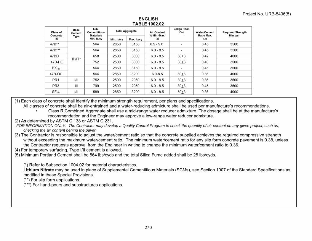
Project No. URB-5436(5)
- 270 -
ENGLISH TABLE 1002.02
Class of Concrete
(1)
Base Cement
Type
Total Cementitious
Materials Min. lb/cy
Total Aggregate
Air Content % Min.-Max.
(2)
Ledge Rock (%) Water/Cement
Ratio Max. (3)
Required Strength Min. psi
Min. lb/cy Max. lb/cy
47B**
IP/IT*
564 2850 3150 6.5 - 9.0 - 0.45 3500
47B*** 564 2850 3150 6.0 - 8.5 - 0.45 3500
47BD 658 2500 3000 6.0 - 8.5 30+3 0.42 4000
47B-HE 752 2500 3000 6.0 - 8.5 30+3 0.40 3500
BX(4) 564 2850 3150 6.0 - 8.5 - 0.45 3500
47B-OL 564 2850 3200 6.0-8.5 30+3 0.36 4000
PR1 I/II 752 2500 2950 6.0 - 8.5 30+3 0.36 3500
PR3 III 799 2500 2950 6.0 - 8.5 30+3 0.45 3500
SF(5) I/II 589 2850 3200 6.0 - 8.5 50+3 0.36 4000
(1) Each class of concrete shall identify the minimum strength requirement, per plans and specifications. All classes of concrete shall be air-entrained and a water-reducing admixture shall be used per manufacture’s recommendations.
• Class R Combined Aggregate shall use a mid-range water reducer admixture. The dosage shall be at the manufacture’s recommendation and the Engineer may approve a low-range water reducer admixture.
(2) As determined by ASTM C 138 or ASTM C 231. FOR INFORMATION ONLY. The Contractor may develop a Quality Control Program to check the quantity of air content on any given project; such as,
checking the air content behind the paver. (3) The Contractor is responsible to adjust the water/cement ratio so that the concrete supplied achieves the required compressive strength
without exceeding the maximum water/cement ratio. The minimum water/cement ratio for any slip form concrete pavement is 0.38, unless the Contractor requests approval from the Engineer in writing to change the minimum water/cement ratio to 0.36.
(4) For temporary surfacing, Type I/II cement is allowed. (5) Minimum Portland Cement shall be 564 lbs/cyds and the total Silica Fume added shall be 25 lbs/cyds.
(*) Refer to Subsection 1004.02 for material characteristics. Lithium Nitrate may be used in place of Supplemental Cementitious Materials (SCMs), see Section 1007 of the Standard Specifications as modified in these Special Provisions. (**) For slip form applications. (***) For hand-pours and substructures applications.

Project No. URB-5436(5)
- 271 -
Table 1002.03 Table of Acceptable Concrete Class Substitutions Class Specified Acceptable Class for Substitution
BX 47B, 47BD or 47B-HE 47B 47BD or 47B-HE
Paragraphs 5., 6., 7., 8., 9. and 10. of Subsection 1002.02 are void and superseded by the following:
5. Class PR1 and PR3 Concrete:
a. The calcium chloride for use in PR concrete shall be either:
(1) A commercially prepared solution with a concentration of approximately 32 percent by weight.
(2) A Contractor prepared solution made by dissolving 4.5 pounds of
Grade 2 or 6.2 pounds of Grade 1 calcium chloride per gallon of water to provide a solution of approximately 32 percent by weight.
b. The 7.4 pounds of water in each gallon of solution shall be considered
part of the total water per batch of concrete.
c. The calcium chloride solution shall be added, just prior to placement, at a rate of 0.375 gallons/100 pounds of cement (1.4 lb. calcium chloride per 100 lb. cement).
d. Class A, Flaked or Pellet Calcium Chloride shall be added at a rate not to
exceed 2.0 percent of the weight of the cement for Grade 1, or 1.6 percent of the weight of the cement for Grade 2. Grade 1 Calcium Chloride purity is between 70 and 90 percent and Grade 2 Calcium Chloride is between 91 and 100 percent.
e. Where mixing trucks are used:
(1) For Class PR3 Concrete, calcium chloride shall be thoroughly
mixed into the concrete before placement. The minimum mixing time is 2 minutes.
(2) For Class PR1 Concrete, calcium chloride shall be added first and
then the concrete mixed at least 2 minutes or as required by manufacturer. Next, the Type F high range water-reducer admixture is added and the concrete is mixed an additional 5 minutes.
6. Class High Early (47B-HE) Concrete
a. High Early (47B-HE) concrete shall be cured as prescribed in
Subsection 603.03, Paragraph 7. The Contractor shall take necessary curing measures so the required strength is achieved.
b. High Early concrete shall achieve a compressive strength of 3,500 psi at
48 hours after placement.

Project No. URB-5436(5)
- 272 -
c. The 48-hour compressive strengths shall be used to determine pay factor
deductions for high early concrete in accordance with Table 603.03.
d. A non-calcium chloride accelerator shall be used when the ambient temperature at the time of the placement of concrete is 70°F or less.
e. When requested by the Contractor, the maturity method, as provided in
NDR C 1074, may be used in lieu of the requirements of Subsection 603.03, Paragraphs 11.c. and d. to determine the strength of concrete pavement for the purpose of early opening to traffic and acceptance. Requests by the Contractor for use of the maturity method shall be on a project basis and shall be made in writing to the Engineer.
7. The yield of the concrete proportions shall be determined and adjusted by the
Producer. 8. All Classes of Concrete with the exception of PR1 and PR3 shall have a
Durability Factor not less than 70 and a mass loss not greater than five percent after 300 freeze/thaw cycles when tested in accordance with ASTM C 666. The freeze/thaw testing shall be conducted according to Procedure A.
Paragraphs 1. & 2. of Subsection 1002.03 are void and superseded by the following: 1. The Contractor shall identify the plant that will supply the concrete 14 days
before use and be entirely responsible for its calibration, batching of concrete, aggregate and sampling of cement per NDR Sampling Guide.
a. The Contractor shall be responsible for the following: 1) Batching concrete. 2) Contractor shall sample aggregate from the conveyor belt or
stockpile. Gradations from a split sample shall be tested in accordance to Section 1033 and reported to the Engineer at the frequency required by the Materials Sampling Guide.
i. Contractor shall retain possession of the split samples on-site at the Contractor’s facility until such a time as determined by the Engineer.
a. At the pre-construction meeting: 1) Contractor shall determine the location of
testing and report the names of the technician performing the sampling and testing.
2) Engineer will notify the Contractor of the retrieval of the split samples.
ii. The Contractor shall split the sample, place the Department’s split sample into a cloth bag and immediately seal the split sample with the provided security seal. The cloth sample bag shall be supplied by the Department.
iii. The sampling splitting and placement of the security seal of aggregate samples shall be witnessed by certified Department personnel.

Project No. URB-5436(5)
- 273 -
iv. Contractor shall secure the split sample using a consecutively numbered security seal of 75 pounds breaking strength provided by the Department. The Contractor shall use the consecutively numbered security seals to identify and track each Aggregate Class. Samples that are not consecutively numbered will be investigated for custody of the sample and the Engineer may cease production until it is determined what action will be required.
a. The Contractor shall report the security seal tracking number with the split sample gradation.
b. The following training shall be required for personnel who oversee the batching of the concrete:
1) Concrete Technician Personnel i. Concrete Plant Technician 2) Portland Cement Sampler i. NDR Portland Cement Sampler 2. Portland Cement Concrete shall be supplied by certified Ready Mix Plants that
are in compliance with the requirements in the Quality Control Manual, Section 3, -- Certification of Ready Mixed Concrete Production Facilities published by the National Ready Mixed Concrete Association. Refer to NDR Material Sampling Guide for the policy on stationary and portable plants.
Paragraph 4. of Subsection 1002.03 is void and superseded by the following: 4. a. Mix times shall meet the requirements of ASTM C 94. Mixing time tests
shall be repeated whenever the concrete appearance indicates that mixing was inadequate.
b. Batch plants that are transporting the concrete in non-agitating trucks, the
mixing time will not be less than 60 seconds, and for agitating trucks, the mixing time will not be less than 45 seconds.
c. The Certification of stationary and portable ready mix plants will conform
to the tests that are required in the NDR Materials Sampling Guide. Paragraph 6. of Subsection 1002.03 is void and superseded by the following: 6. Batch tickets shall be prepared as prescribed in the National Ready Mixed
Concrete Association's Quality Control Manual. The Contractor shall keep all gradations and batch tickets until final acceptance by the Department. Projects that have less than 200 cubic yards of concrete placed will be allowed to have hand written tickets. For projects greater than 200 cubic yards, hand written tickets will be at the Engineer’s discretion. The concrete batch tickets shall show batch weights, aggregate moisture (shall be tested daily and moisture probes are allowed), admixtures used, water, and mix design calculations. A copy of the batch ticket shall be given to the Engineer upon delivery of concrete.

Project No. URB-5436(5)
- 274 -
Paragraph 8. of Subsection 1002.03 is void and superseded by the following: 8. Coarse aggregate and aggregate from a dry pit shall be uniformly saturated with
water before it is used. The wetting shall begin 24 hours prior to the concrete mixing to allow complete saturation.
Paragraph 13.a. of Subsection 1002.03 is void and superseded by the following: 13. a. The quantity of water shall be determined by the Contractor. The minimum
quantity of water should be used which will produce required workability. Any additional water used to rinse the charging hopper and fins after the batching of concrete is allowed. This water must be estimated and recorded on the batch ticket.
Subsection 1002.04 is void and superseded by the following: 1. Class 47B Concrete Mix Design Submittal: a. The Contractor shall submit the Concrete Mix Design Worksheet
consisting of design mix proportions, testing of mix design from a minimum of 4 cubic yards and aggregate data for 47B class of concrete being placed on the project.
(1) All testing must be performed by a qualified laboratory found on
the NDR’s Material and Research website, under the Nebraska Qualified Consultant & LPA Laboratories and submitted to the Engineer.
(2) The Concrete Mix Design shall be submitted to the Engineer
4 weeks prior to any concrete being placed on the project. (3) The Concrete Mix Design shall not be paid for directly by the
Department and shall be subsidiary to items which direct payment is made.
(4) Concrete shall not be placed on the project before the Concrete
Mix Design Worksheet has been reviewed and approved by the Engineer.
b. The Contractor shall submit the Concrete Mix Design Worksheet to the
Engineer. Email submissions are preferred but will be accepted by fax or postal mail.
(1) Contractor’s Mix Design Worksheet can be found on the Materials
and Research website. The submitted Mix Design Worksheet shall include the following:
Contractor Name Project Number Date Location of ready mix or central mix plant Date submitted Signature of Contractor representative

Project No. URB-5436(5)
- 275 -
(2) Material Source Information.
Cement Manufacturer Type of Interground/Blended Cement Type of Admixtures Aggregate Pit and Quarry location
(3) Specific Gravity of each individual aggregate source.
(4) Sand Equivalent for dry pit sand-gravel aggregate.
(5) Combined Aggregate percent passing as described on
Table 1033.03C.
(6) Contractor’s Target combined aggregate gradation percent passing.
(i) The Contractor’s required worksheet can be found on the Materials and Research website.
(7) Testing of Mix Design:
The mix design shall show the weights of all ingredients
including Interground/Blended cements, aggregates, water, admixtures types and water cement ratio.
Temperature of concrete at time of sampling, ASTM C 1064.
The air content of plastic concrete, ASTM C 231.
Weight per cubic foot, Yield, ASTM C 138. The relative Yield shall be a minimum of 97%.
Compressive strength shall be performed with a minimum of three averaged specimens at 7-day and 28-day, ASTM C 39. The minimum 28-day compressive strength shall be 3500 psi.
(8) Traditional 47B Mix Design is defined as an IP(25) cement,
70 percent Class B Aggregate and 30 percent Class E Aggregate may be exempt from the concrete testing described in Paragraph 1.(b)(7). All other requirements shall be included in the Concrete Mix Design Report.
c. The PCC Engineer will notify the Contractor of the mix design approval
for Class 47B Concrete. Approval of the mix design does not alleviate the Contractor of the responsibility of the in-place concrete. The Contractor may adjust admixtures, water cement ratio, vibrator frequency, etc., as needed in accordance to the specifications.
d. The Contractor shall submit a new concrete mix design worksheet
meeting the above requirements when a change occurs in the source,

Project No. URB-5436(5)
- 276 -
type, or proportions of cements or aggregates; unless otherwise approved by the Engineer.
2. The quantity of water to be used shall be determined by the Contractor. It shall
not be varied without the Engineer's consent. 3. If the concrete mixture is excessively wet causing segregation, excessive
bleeding, excessively dry or any other undesirable condition, the concrete shall be rejected. At the option of the Engineer, slump tests may be performed to determine the consistency.
4. Concrete which has developed initial set before it is consolidated and finished
shall be rejected. 5. a. If false set is encountered, the batching operation shall be stopped until
the problem is resolved. b. Each batch must be mixed or agitated for at least 3 additional minutes
after observing the false set and the concrete must be of satisfactory consistency.
6. Compressive strength tests shall be made in accordance with ASTM C 39. 7. Concrete shall be sampled as prescribed in the NDR Materials Sampling Guide.
Samples shall be taken at the point of placement, never before the discharge from the last conveyance.
8. Aggregate Acceptance, Verification, Sampling and Testing: a. The aggregate will be accepted based on the Contractor’s testing results
except as noted below. b. The aggregate verification sampling and testing by the Department will be
randomly selected and tested according to sublot sizes in Table 1002.05.
Table 1002.05
c. The results of Contractor split sample will be verified by the Department’s verification tests. Any samples outside of the tolerances as specified according to the Materials Sampling Guide, Section 28 under the Acceptable Tolerance Limits for Independent Assurance will result in an Independent Assurance (IA) review of testing and may result in the Department test results being applied.
d. On any given Lot, if the results of the gradation from the verification test
are within Department’s specification, the Contractor’s results will be used for the entire lot. On any given Lot, if the gradations results from the
Aggregate Class Lot Sublot
E and F 3000 tons 1000 tons
A,B and C 6000 tons 2000 tons
R 3000 tons 1000 tons

Project No. URB-5436(5)
- 277 -
verification test are outside Department’s specification, further investigation will be initiated by the Engineer for that sublot. Any or all of the remaining Department sublot samples may be tested and the Department sublot test results may be applied to the respective sublot and the acceptance will apply.
e. When verification tests are within testing tolerance but results show a
consistent pattern of deviation from the split sample results, the Engineer will exercise one or more of the following:
- Cease production. - Request additional verification testing. - Initiate a complete IA review.
f. Independent Assurance (IA) Review of Testing: 1) The Contractor shall allow the Department personnel access to
the Contractors’ laboratory to conduct IA review of the technician testing procedures and apparatus. Any deficiencies discovered in the Contractor’s testing procedures will be reported to the Contractor and corrected by the Contractor.
2) During the IA review, the Department personnel and the
Contractor shall split a sample for the purpose of IA testing. The samples selected will be tested in the Department’s Branch Laboratory. Any IA test results found to be outside of defined testing tolerances as stated in Paragraph 8.c. of Subsection 1002.04 will be reported to the Contractor. The Contractor shall immediately correct any deficiencies found during the IA review.
3) If the project personnel and the Contractor cannot reach
agreement on the accuracy of the test results, the Department Central Laboratory will be asked to resolve the dispute, which will be final. All dispute resolutions will be in accordance with the Quality Assurance Program requirements in the NDR’s Materials Sampling Guide.
PORTLAND AND INTERGROUND/BLENDED CEMENT (J-15-0214)
Section 1004 in the Standard Specifications is void and superseded by the following: 1004.01 – Description 1. Portland cement is the binder in concrete, locking the aggregate into a solid structure. It
is manufactured from Lime, Silica, and Alumina (with a small amount of plaster of Gypsum).
2. Equivalent alkali referred to herein is hereby defined as the sum of the Sodium Oxide
(Na20) and the Potassium Oxide (K20) calculated as Equivalent Alkali Na20e = Na20+ 0.658 K20.

Project No. URB-5436(5)
- 278 -
3. Interground and Blended cements consist of intimate and uniform intergrinding or
blending of Portland cement clinker, Slag cement, Pozzolan and/or Limestone. 1004.02 – Material Characteristics 1. Type I, Type II, Type I/II and Type III Portland cement shall conform to the requirements
in ASTM C 150 with the following additional requirements:
a. Portland cement shall not contain more than 0.60 percent equivalent alkali.
b. Processing additions may be used in the manufacture of the cement, provided such materials have been shown to meet the requirements of ASTM C 465 and the total amount does not exceed 1 percent of the weight of Portland cement clinker.
2. Interground and Blended Cement shall conform to the requirements in ASTM C 595 with
the following additional requirements: a. Interground/Blended cement (Type IP) (1) For Type IP(25) shall be composed of Class F fly ash or Class N
pozzolan replacement shall be 25% + 2%. (2) For Type IP(20) shall be composed of Class F fly ash or Class N
pozzolan replacement shall be 20% + 2%. b. Interground/Blended cement (Type IT)
(1) For SCMs, Slag cement and Limestone, the maximum replacement by weight shall be 40%. The manufacturer has a production tolerance of + 2% from the proposed replacement.
(2) For Slag Cement, the maximum replacement shall be 20% or less when
incorporated into the final Interground/Blended cement.
(3) For Limestone cement, the replacement range shall be from 5.1% to 10.0% when incorporated into the final Interground/Blended cement.
c. No additional SCMs, Slag cement and Limestone will be added at the batch
plant. 1004.03 – Procedures 1. The Contractor shall provide adequate protection for the Portland and
Interground/Blended cement against dampness. a. Portland and Interground/Blended cement shall be hauled or stored in railroad
cars, dry bulk trailers or in suitable moisture-proof buildings. b. The use of tarpaulins for the protection of the Portland and Interground/Blended
cement against moisture will not be allowed.

Project No. URB-5436(5)
- 279 -
2. No Portland and Interground/Blended cement which has become caked or lumpy shall be used.
3. Portland and Interground/Blended cement which has been spilled shall not be used. 4. Accepted Portland and Interground/Blended cement which has been held in storage at
the concrete mix plant more than 90 days shall be retested. 5. Portland and Interground/Blended cement coming directly from the manufacturer shall
not be used until the temperature is 150°F or less. 6. Portland cement having false set when tested in accordance with in ASTM C 150 will not
be used. 1004.04 – Acceptance Requirements 1. For Department projects, Portland and Interground/Blended cements must be on the
NDR Approved Product List (APL). 2. The Contractor shall submit any new Portland and Interground/Blended cements to the
Engineer to be approved for the APL with the following: a. Material source information: 1) Mill Location 2) Type of Portland and Interground/Blended cements 3) Grinding Period 4) Associated Manufacture Product Name 5) Provide source and type of each SCMs and/or Slag Cement used for final
product. (i) The Department will allow the use of ASTM C 1697. a. When two or more SCMs and/or Slag Cement are pre-
blended, the Contractor shall report chemical composition analysis of the final blend.
b. The final blend shall be reported as per ASTM C 1697, Paragraph 4.
6) Portland cement shall conform to ASTM C 150. 7) Interground/blended cements shall conform to ASTM C 595. 8) Provide total cementitious materials replacement per ASTM C 595. 9) Report test results per ASTM C 1567 at 28-days.

Project No. URB-5436(5)
- 280 -
3. Alkali Silica Reaction Requirements and Testing: a. Interground/Blended cement shall be tested according to the provisions of
ASTM C 1567. (1) The mortar bars shall be composed of Type IP or IT Interground/blended
cement and sand and gravel from an approved Platte River Valley-Saunders County source.
i. When Elkhorn River-Madison County source or an out of state aggregate source and type IP(20) or IT cement is being used on a project, the Elkhorn River or an out of state aggregate source shall be used in lieu of the Platte River Valley-Saunders County source.
ii. When Contractor proposes a change of aggregate source, then the new aggregate source shall be tested by ASTM C 1567.
(2) The mortar bars for the ASTM C 1567 shall not exceed 0.10% expansion
at 28 days. i. To accommodate precision within multi-laboratory testing,
expansion up to and including 0.13% will be accepted for use. If the expansion is above 0.13%, the material is noncompliant. If tolerance problems are not corrected within 30 days following notification, the Interground/blended cement in question will be removed from the NDR’s APL.
4. Portland and Interground/Blended cements will be placed on NDR’s APL based on the
conformance with the NDR’s Acceptance Policy Portland and Interground/Blended Cements.
1004.05 - Sampling and Testing Requirements 1. All Portland and Interground/Blended cements shall be sampled and tested at the rate
as described in the NDR’s Materials Sampling Guide. a. The Department will inform the Contractor when a sample is required. b. A sample shall be taken by a Contractor’s Certified Portland Cement Sampler
and must be under the supervision of Department certified personnel. c. The sample shall be taken at the plant from a bulk shipment of a rail car, dry bulk
trailer, batch plant silo or from the line between the bulk truck and the silo. Upon sampling, the Department will take immediate custody of the sample.
d. When Elkhorn River aggregate- Madison County source or an out of state
aggregate source and type IP(20) or IT cement is being used on a project, the Elkhorn River or an out of state aggregate source shall be used in lieu of the Platte River Valley aggregate source.
2. Noncompliant material from the mill, terminal or project will be temporarily removed from
the Approved Products List pending further investigation. 3. If the noncompliant Portland or Interground/Blended cement is removed from the
Approval Products List, all shipments from the supplier will be held until the investigation

Project No. URB-5436(5)
- 281 -
of the failing samples have been completed by the NDR Materials and Research Division. These procedures shall be in accordance with this provision.
WATER FOR CONCRETE (J-15-0214)
Section 1005 in the Standard Specifications is void and superseded by the following: 1005.01 – Description 1. Water shall be free from objectionable quantities of oil, acid, alkali, salt, organic matter,
or other deleterious materials and shall not be used until the source of supply has been approved.
2. Wash water from the mixer washout may be used only with the Engineer’s approval.
Use of wash water will be discontinued if undesirable reaction with admixtures or aggregates occurs.
1005.02 – Material Characteristics
1. Water which contains more than 0.25 percent total solids by weight shall not be used. 2. When required by the Engineer, the quality of mixing water shall be determined by
NDR C 114, NDR T 290, NDR D 512, NDR C 1602, ASTM C 31, ASTM C 109, ASTM C 191, and ASTM C 1603.
3. Upon written request by the concrete producer and approval by Materials and Research,
the concrete producer may utilize up to 10% wash water for batching all classes of concrete with the following conditions:
a. Wash water shall conform to the requirements in NDR’s Material Sampling Guide
under Policy for Certification of Ready Mix Plants. b. Wash water must be clarified wash water that has been passed through a settling
pond system. c. Wash water must be scalped off of a settling basin that has been undisturbed for
a minimum of 12 hours. d. Wash water must be metered into each load. e. Wash water quantities shall be shown on the batch ticket.
CALCIUM CHLORIDE (J-15-0214)
Section 1006 of the Standard Specifications is void and superseded by the following: 1006.01 – Description
Calcium Chloride shall be Type S (Solid) or Type L (Liquid). Calcium Chloride can be used for; but not limited to, dust control and acceleration of the set of concrete.

Project No. URB-5436(5)
- 282 -
1006.02 – Material Characteristics The requirements for calcium chloride shall be tested in accordance with ASTM D 98. 1006.03 – Acceptance Requirements Acceptance shall be based on requirements contained in the NDR Materials Sampling Guide.
SECTION 1007 -- CHEMICAL ADMIXTURES (J-15-0214)
Section 1007 in the Standard Specifications is void and superseded by the following: 1007.01 -- Description 1. Admixtures are materials added to Portland cement concrete to change characteristics
such as workability, strength, permeability, freezing point, and curing. 2. The Department's concrete admixture types are: a. Type A - Water-Reducing Admixture - An admixture that reduces the quantity of
mixing water required to produce concrete of a given slump. b. Type B - Retarding Admixture - An admixture that slows the setting of concrete. c. Type C - Accelerating Admixture - An admixture that speeds the setting and early
strength development of concrete. d. Type D - Water-Reducing and Retarding Admixture - An admixture that reduces
the quantity of mixing water required to produce concrete of a given slump and slows the setting of concrete.
e. Type E - Water-Reducing and Accelerating Admixture - An admixture that
reduces the quantity of mixing water required to produce concrete of a given slump and speeds the setting and early strength development of concrete.
f. Type F - Water-Reducing, High Range Admixture - An admixture that reduces
the quantity of mixing water required to produce concrete of a given slump by 12 percent or greater.
g. Type G - Water-Reducing, High Range and Retarding Admixture - An admixture
that reduces the quantity of mixing water required to produce concrete of a given slump by 12 percent or greater and slows the setting of concrete.
h. Air-Entraining - An admixture that encapsulates air in the concrete. i. Lithium Nitrate – An admixture used to control the Akali Silica Reaction (ASR) in
concrete.

Project No. URB-5436(5)
- 283 -
1007.02 -- Material Characteristics 1. Type A through G admixtures shall meet the requirements in ASTM C 494. 2. Air-entraining admixtures shall meet the requirements in ASTM C 260. 3. Use of admixtures other than those cited may be requested by the Contractor. 4. Admixtures shall not contain more than 1 percent of chlorides calculated as calcium
chloride unless specified otherwise in the Specification. 5. Admixtures shall be used at the manufacturer's recommended dosage rates. 6. The air-entraining admixture characteristics shall produce concrete with satisfactory
workability and total air content as prescribed in Table 1002.02. 7. a. When using the Lithium Nitrate admixture, the Contractor shall submit to the
Engineer: (i) A five pound sample of Portland cement that will be used on the project. (ii) The Manufacturer’s method for determining the recommendation for the
required dose rate based on the equivalent alkali content. (iii) Water content of the Lithium Nitrate admixture solution. b. The Engineer will report the equivalent alkali content to the Contractor. The
Contractor shall use the reported equivalent alkali content to determine the required dose rate based on the manufacturer’s recommendation.
1007.03 -- Procedures 1. The process for adding admixtures to a ready mix truck on the project site involves
positioning the load of concrete up to the truck chute, stopping short of discharge. a. The admixture is then poured over the surface of the concrete and mixed for at
least 5 minutes. b. No more than 1.3 gallons of water shall be used to rinse the admixture from the
fins and top chute. This water must be shown on the proportioning report and shall not exceed the water cement ratio.
c. When Lithium Nitrate is used, the portion of the admixture that is water will be
shown on the proportioning report and shall not exceed the water cement ratio. d. The Contractor is responsible for the addition of the admixture. 2. a. If the air content is less than the minimum specified, addition of air-entraining
admixtures is allowed. b. The Contractor shall take measures based on manufacturer’s recommendations,
that are within compliance of NDR Specifications, to bring the load of concrete into NDR prescribed limits according to Table 1002.02.

Project No. URB-5436(5)
- 284 -
c. If the air content is then outside the limits in Table 1002.02, the load of concrete shall be rejected.
1007.04 -- Acceptance Requirements 1. a. Approved chemical admixtures are shown on the NDR Approved Products List. b. Admixture approval shall be based upon annual certifications and certified test
results submitted to the NDR Materials and Research Division. 2. The admixture must be essentially identical in concentration, composition, and
performance to the admixture tested for certification. 3. Admixtures not identified on the NDR Approved Products List may be used under the
following conditions: a. A certificate of compliance and certified test results must be submitted to the
NDR Materials and Research Division and approval for use must be given by the NDR Materials and Research Division.
SILICA FUME (J-15-0307)
Paragraph 2 of Subsection 1009.03 in the Standard Specifications is void and superseded by the following:
2. Silica fume shall be protected from temperatures in excess of 90°F (32°C).
LIQUID MEMBRANE-FORMING COMPOUNDS FOR CURING CONCRETE (J-15-0307)
Subsection 1012.03 in the Standard Specifications is void and superseded by the following: 1012.03 – Acceptance Requirements 1. All curing compounds to be approved must be from the current calendar year with no
carry-over from the previous years. 2. Approved compounds are on the NDR Approved Products List. 3. Products not on the NDR Approved Products List shall be sampled and tested in
accordance with requirements of the NDR Materials Sampling Guide.

Project No. URB-5436(5)
- 285 -
BITUMINOUS LIQUID COMPOUNDS FOR CURING CONCRETE (J-15-1007)
Section 1013 in the Standard Specifications is void and superseded by the following: 1013.01 – Description The compound shall consist essentially of an asphaltic base and shall be of a consistency suitable for spraying at temperatures existing at the time of construction operations. It shall form a continuous, uniform film. It shall be free of precipitated matter caused by conditions of storage or temperature. The compounds shall be relatively nontoxic. 1013.02 – Material Characteristics
a. When tested in accordance with AASHTO T 155, the loss of water shall not be more than 0.11 lb/ft2 (0.55 kg/m2) of surface area at 3 days, unless otherwise specified by the Engineer.
b. The Contractor has the option of using bituminous tack coat. The tack coat shall
conform to all requirements of Section 504. 1013.03 – Acceptance Requirements Products shall be sampled and tested in accordance with requirements of the NDR Materials Sampling Guide.
JOINT AND CRACK SEALING FILLER (J-15-0813)
Section 1014 in the Standard Specifications is void and superseded by the following: 1014.01 – Description Joint sealing filler shall be either a cold applied silicone product or an asphalt product (hot pour) conforming to the requirements of this Section. The type of joint filler to be used shall be as specified in the plans or special provisions. If not specified, any of the joint sealing fillers in this Section may be used. Crack sealing filler shall be a hot pour sealer conforming to the requirements of this Section. 1014.02 -- Material Characteristics 1. NE-3405 and NE-3405LM (hot pour) a. NE-3405 joint and crack sealer shall conform to the requirements of ASTM
D6690, Type II. The material shall conform to the requirements of Table 1 with the following exception:
(i) The test of Bond, non-immersed, ASTM D5329, 3 specimens through
3 cycles shall be run at 0F (-18oC), 100% extension.

Project No. URB-5436(5)
- 286 -
b. NE-3405LM (Low Modulus) joint and crack sealer shall conform to the requirements of ASTM D6690, Type IV. The material shall conform to the requirements of Table 1.
c. The test of Bond, non-immersed, ASTM-D5329, will be tested on concrete blocks
that will be constructed by the NDR Concrete Laboratory. The concrete blocks will be made of a 47B concrete mixture as prescribed in Section 1002 in the NDR Standard Specifications. The design is amended so that no fly ash is used in the mixture. All other specifications for Portland Cement Concrete apply.
d. Sample conditioning, preparation and heating shall be in accordance with
ASTM D 5167 with the following exceptions: (i) The following sentence of Section 8.1.2, “Also, if present, remove
container liner by cutting it away”, is void and superseded by the following:
“Also, if present, as much of the polyethylene bag as possible,
shall be removed by cutting it away. Wholly-meltable type container in contact with the sample section shall be left in place.”
(ii) The last sentence of Section 8.1.2 “Solid Materials” is void and
superseded by the following: The entire vertical section which has been cut, shall be placed into
the pot for melting. (iii) The Section of 8.2.2.1 “Solid Materials” is void. (iv) The Section of 8.2.3 is void and superseded by the following: After the solid segment is added to the melter, the material shall
be allowed to minimally melt to a uniform viscous state suitable for the installation of the stirrer or paddle. The sample shall then be stirred for one full hour. The oil bath temperature shall be regulated to bring the material to the maximum heating temperature within the one hour of stirring.
(v) The Section of 8.2.4.1 is void and superseded by the following: During the one full hour of stirring, check the temperature of the
material at maximum 15 minute intervals using a Type K thermocouple with the calibration verified in accordance with Section 6.1.7 to ensure conformance with specified temperature requirements. Stop the mechanical stirrer when measuring temperatures. If material temperatures ever exceed the maximum heating temperature, or ever drop below the minimum application temperature after the maximum heating temperature was reached, discard the sample and re-do the heating. Maintain appropriate records of times and temperatures to verify conformance with specification requirements.
(vi) The Section of 8.2.4.2 is void.

Project No. URB-5436(5)
- 287 -
e. ASTM D 5329 shall include the following changes: (i) Sections 6.4 and 12.4 “Specimen Preparation” shall have the reference of
“177 ml (6 oz.)” replaced with “3 oz.” (ii) Section 6 “Cone Penetration, Non-Immersed” shall be superseded with
the following exceptions: 1. Section 6.5 “Procedure” is void and superseded by the following: Place the specimen in a water bath maintained at 77 +/-
0.2°F (25 +/- 0.1C) for two hours immediately before testing. Remove the specimen from the bath and dry the surface by shaking gently to remove free water from the surface of the specimen. Using the apparatus described in Section 6.3, make one determination at or near the center of the specimen. Take care to ensure the cone point is placed on a point in the specimen that is representative of the material itself, and is free of dust, water, bubbles, or other foreign material.
2. Section 6.6 “Report” is void and superseded by the following: Record the value as penetration of the specimen in dmm
units. (iii) Section 12 “Resilience” shall be superseded with the following
exceptions: 1. Section 12.5 “Procedure”, void the sentence “Make determinations
at three points equally spaced from each other and less than 13mm (½ inch) from the container rim” and supersede with the sentence “Make one determination at or near the center of the tin.”
2. Section 12.6 “Report” is void.

Project No. URB-5436(5)
- 288 -
2. Silicone Joint Sealer (cold applied) a. Silicone joint sealers may be either self-leveling or non-sag and shall meet the
requirements in Table 1014.01.
Table 1014.01 Silicone Joint Sealer Requirement
Property Requirement Test As supplied: Specific Gravity Work Time, minimum Tack-Free, at 25°C Cure Time, at 25°C, maximum Full Adhesion, maximum
1.010-1.515 10 minutes 20-360 minutes 14 days 21 days
ASTM D792
As cured, at 25°C + 1.5 Elongation, minimum Durometer Non-Sag, Shore A Self-Leveling, Shore 00, minimum Joint Movement Capacity Tensile Stress, at 150% Elongation
800% 10-25 40 +100% to -50% 45 psi
ASTM D412 ASTM D2240 ASTM D2240 ASTM C719 ASTM D412
1014.03 -- Packaging 1. NE-3405 and NE-3405LM a. The joint and crack sealer can be packaged in either cardboard box of wholly-
meltable type containers. (i) Cardboard box containers shall be manufactured from double wall kraft
board producing a minimum bursting test certification of 350 PSI (241 N/cm2) and using water-resistant adhesives. The use of metal staples or fasteners of any kind will be prohibited for closing the lids of the boxes. Tape or other like material is acceptable.
a. The joint and crack sealer shall be in meltable [300°F (149C)]
polyethylene bag(s). (ii) Wholly-meltable type containers, and any of their components, shall be
fully meltable and integrational with the joint and crack sealer by the time the manufacturer’s minimum application temperature is reached.
a. The wholly-melted and integrated container must not adversely
affect the test specifications of the joint and crack sealer. 2. Silicone Joint Sealer a. Each container shall include information regarding manufacturer and product
name.

Project No. URB-5436(5)
- 289 -
1014.04 -- Acceptance Requirements 1. NE-3405 and NE-3405LM a. Acceptance of the manufactured material is based on pre-approval by either on
or off-site sampling. Acceptable hot pour sealant lots are listed on the NDR Approved Products List.
(i) NDR on-site field sampling shall be in accordance with the NDR Materials
Sampling Guide. (ii) Off-site (Proxy) sampling shall be in accordance with ASTM D 6690. 1. Proxy sampling shall be overseen by an outside party approved
by the NDR, preferably another DOT Agency. Proxy samples shall include a manufacturer’s Certificate of Compliance. Proxy samples shall also include a dated signature of origin by the Representative that is not affiliated with the manufacturer, and can either be on the Certificate of Compliance, or separate letter.
2. For convenience in both sampling and shipping samples, sample
containers smaller than a manufacturer’s usual production containers are allowed, as long as the sample is 1500 grams min.
3. Samples shall be sent to the NDR Bituminous Laboratory, or
alternatively, sent to an NDR-approved independent laboratory for testing which will be at no cost to the Department. If a NDR-approved independent laboratory will be used for testing purposes, the NDR Bituminous Laboratory must be notified so that NDR concrete blocks for Bond testing can be sent to it.
2. Silicone Joint Sealer a. Acceptance of applied silicone joint sealers shall be in accordance with the NDR
Materials Sampling Guide. b. Acceptable silicone joint sealer manufacturer products are listed on the NDR
Approved Products List. (i) For products that are not listed, approval may be based upon test results
from an independent laboratory submitted to the NDR Concrete Materials Section by the manufacturer, and testing by the NDR. Approval must be made prior to product use.
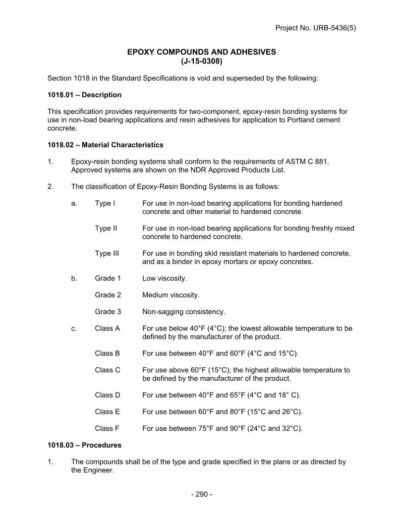
Project No. URB-5436(5)
- 290 -
EPOXY COMPOUNDS AND ADHESIVES (J-15-0308)
Section 1018 in the Standard Specifications is void and superseded by the following: 1018.01 – Description This specification provides requirements for two-component, epoxy-resin bonding systems for use in non-load bearing applications and resin adhesives for application to Portland cement concrete. 1018.02 – Material Characteristics 1. Epoxy-resin bonding systems shall conform to the requirements of ASTM C 881.
Approved systems are shown on the NDR Approved Products List. 2. The classification of Epoxy-Resin Bonding Systems is as follows: a. Type I For use in non-load bearing applications for bonding hardened
concrete and other material to hardened concrete. Type II For use in non-load bearing applications for bonding freshly mixed
concrete to hardened concrete. Type III For use in bonding skid resistant materials to hardened concrete,
and as a binder in epoxy mortars or epoxy concretes. b. Grade 1 Low viscosity. Grade 2 Medium viscosity. Grade 3 Non-sagging consistency. c. Class A For use below 40°F (4°C); the lowest allowable temperature to be
defined by the manufacturer of the product. Class B For use between 40°F and 60°F (4°C and 15°C). Class C For use above 60°F (15°C); the highest allowable temperature to
be defined by the manufacturer of the product. Class D For use between 40°F and 65°F (4°C and 18° C). Class E For use between 60°F and 80°F (15°C and 26°C). Class F For use between 75°F and 90°F (24°C and 32°C). 1018.03 – Procedures 1. The compounds shall be of the type and grade specified in the plans or as directed by
the Engineer.
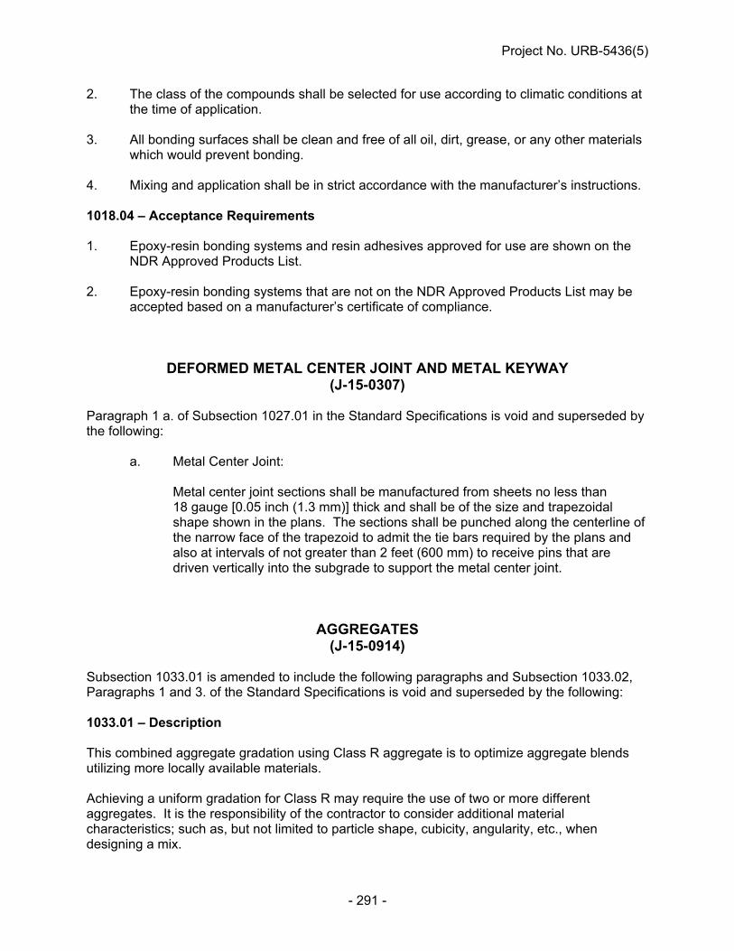
Project No. URB-5436(5)
- 291 -
2. The class of the compounds shall be selected for use according to climatic conditions at the time of application.
3. All bonding surfaces shall be clean and free of all oil, dirt, grease, or any other materials
which would prevent bonding. 4. Mixing and application shall be in strict accordance with the manufacturer’s instructions. 1018.04 – Acceptance Requirements 1. Epoxy-resin bonding systems and resin adhesives approved for use are shown on the
NDR Approved Products List. 2. Epoxy-resin bonding systems that are not on the NDR Approved Products List may be
accepted based on a manufacturer’s certificate of compliance.
DEFORMED METAL CENTER JOINT AND METAL KEYWAY (J-15-0307)
Paragraph 1 a. of Subsection 1027.01 in the Standard Specifications is void and superseded by the following:
a. Metal Center Joint:
Metal center joint sections shall be manufactured from sheets no less than 18 gauge [0.05 inch (1.3 mm)] thick and shall be of the size and trapezoidal shape shown in the plans. The sections shall be punched along the centerline of the narrow face of the trapezoid to admit the tie bars required by the plans and also at intervals of not greater than 2 feet (600 mm) to receive pins that are driven vertically into the subgrade to support the metal center joint.
AGGREGATES (J-15-0914)
Subsection 1033.01 is amended to include the following paragraphs and Subsection 1033.02, Paragraphs 1 and 3. of the Standard Specifications is void and superseded by the following: 1033.01 – Description This combined aggregate gradation using Class R aggregate is to optimize aggregate blends utilizing more locally available materials. Achieving a uniform gradation for Class R may require the use of two or more different aggregates. It is the responsibility of the contractor to consider additional material characteristics; such as, but not limited to particle shape, cubicity, angularity, etc., when designing a mix.

Project No. URB-5436(5)
- 292 -
1033.02 -- Material Characteristics 1. Sampling and Testing Procedures:
All materials shall be sampled and tested in accordance with Table 1033.01. All material source locations and quarries must be approved by the Department for prior to use.
Table 1033.01
Sampling and Testing Procedures Procedure Method Sampling NDR T 2 Sieve Analysis NDR T 27 Clay Lumps, Shale, and Soft Particles NDR T 504 Abrasion AASHTO T 96 Freeze and Thaw Soundness NDR T 103 Specific Gravity and Absorption (course aggregate)
AASHTO T 85
Specific Gravity and Absorption (fine aggregate)
AASHTO T 84
Total Evaporable Moisture Content of Aggregates by Drying Plastic Fines in Graded Aggregates and Soils by Use of the Sand Equivalent Test
AASTHO T 255 AASTHO T 176
Sodium Sulfate Soundness AASHTO T 104 Calcium Carbonate NDR C 25 Organic Impurities AASHTO T 21 Mortar-Making Properties AASHTO T 71 Reducing Field Samples of Aggregate to Testing Size
AASHTO T 248
2. Portland Cement Concrete Aggregates: a. Sand-Gravel Aggregate: (1) Aggregate shall be washed and composed of clean, hard, durable and
uncoated particles. (2) Aggregates produced from wet pits by pumping must be adequately
washed by means approved by the Department. (3) Aggregates from dry pits shall be adequately washed by means approved
by the Department and have a Sand Equivalent value not less than 90 in accordance with AASTHO T 176.
(i) If the Sand Equivalent is less than 90, the Engineer may elect to
stop aggregate production until such a time ASTM C 109 has been completed. The aggregate, when subjected to the test for mortar-making properties, shall produce a mortar having a compressive strength at the age of 7 days equal to or greater than that developed by mortar of the same proportions and consistency made of the same cement and aggregate after the aggregate has been washed to a sand equivalent greater than 90. Materials failing to produce equal or greater strength shall be unacceptable.

Project No. URB-5436(5)
- 293 -
(4) Aggregate for concrete shall have a soundness loss of not more than 10% by weight at the end of 5 cycles using Sodium Sulfate Soundness test AASHTO T 104.
(5) The weight of the aggregate shall not contain more than 0.5% clay lumps.
(6) Aggregate subjected to the colorimetric test for organic impurities which produces a color darker than the standard shall be further tested for its mortar-making properties in accordance with AASHTO T 71. The Engineer may elect to stop aggregate production until such a time AASHTO T 71 testing has been completed.
(i) Aggregate, when subjected to the test for mortar-making
properties, shall produce a mortar having a compressive strength at the age of 7 days equal to or greater than that developed by mortar of the same proportions and consistency made of the same cement and aggregate after the aggregate has been treated in a 3% solution of sodium hydroxide. Materials failing to produce equal or greater strength shall be unacceptable, except when determined to be acceptable under the provisions of Subsection 105.03.
(7) Aggregate shall meet the requirement in Tables 1033.02A, 1033.02B and
1033.03C.
Table 1033.02A
Percentage Percent Passing
1½” 1” ¾” ½” 3/8 No.4 No.10 No.20 No.30 No.200
AGGREGATE SPECIFICATION RANGE
Class A Max Min
-- -- -- -- 100 100 92
90 64
-- 40 10
3 0
Class B Max Min
-- 100 -- -- -- 97 77
70 50
-- 40 16
3 0
Class C Max Min -- 100 -- -- --
88 44
50 24
-- 20 4
3 0
Table 1033.02B
Aggregate Classes and Uses Aggregate Class Concrete Description A Overlay Concrete SF B 47BD, 47B-HE, 47B-OL, PR 1 and PR 3 C BX
b. Ledge Rock Aggregate: (1) Aggregate shall consist of Limestone, Quartzite, Dolomite, Gravel and
Granite composed of clean, hard, durable, and uncoated particles. (2) The percent of clay lumps, shale, or soft particles shall not exceed the
following amounts:
Clay Lumps ......................... 0.5% Shale ................................... 1.0% Soft Particles ....................... 3.5%
(3) Any combination of clay lumps, shale, and soft particles shall not exceed
3.5%.

Project No. URB-5436(5)
- 294 -
(4) Aggregate for concrete shall be free of coatings that will inhibit bond and
free of injurious quantities of loam, alkali, organic matter, thin or laminated pieces, chert, or other deleterious substances as determined by the Engineer.
(5) Aggregate for concrete shall not have a soundness loss greater than
8.0% by weight at the completion of 16 cycles of alternate freezing and thawing.
(6) Aggregates for concrete shall have a Los Angeles Abrasion loss
percentage of not more than 40. (7) All fractions passing the No.4 sieve shall meet quality requirement of
soundness loss of not more than 10% by weight at the end of 5 cycles using sodium sulfate solution.
(8) The ledge rock shall be tested according to ASTM C 1260. (a) The mortar bars for the ASTM C 1260 shall not exceed 0.10%
expansion at 28 days. (i) If the proposed ledge rock exceeds 0.10% expansion at
28 days, the ledge rock shall be tested in accordance to ASTM C 1567. If the expansion is greater than 0.10%, the ledge aggregate shall not be used.
a. The ASTM C 1567 mortar bars shall be composed of Type IP or IT Interground/blended cement and the proposed Ledge Rock aggregate.
b. To accommodate precision within multi-laboratory testing, expansion up to and including 0.13% will be accepted for use. If the expansion is above 0.13%, the material is noncompliant.
(9) Aggregate shall meet the requirements in Tables 1033.03A, B, and C.
Table 1033.03A
Percent Percent Passing
1 ½” 1” ¾” ½” 3/8 No.4 No.10 No.20 No.30 No.200
AGGREGATE SPECIFICATION RANGE
Class E Max Min
100 100 92
90 66
-- 45 15
12 0
-- *4 0
-- 3 0
Class F Max Min
-- -- 100 100 96
90 40
30 4
8 0
-- -- 3 0
*If the No. 200 sieve is less than 1.5% passing the No.20 sieve could be increased to maximum of 6% passing.
Table 1033.03B
Aggregate Classes and Uses Aggregate Class
Concrete Description
E 47BD, 47B-HE, PR 1 and PR 3
F 47B-OL, Overlay Concrete SF

Project No. URB-5436(5)
- 295 -
c. Combined Aggregates: (1) The Contractor shall design and meet the specification requirements. It is
the Contractor’s responsibility to provide desirable mix properties; such as, but not limited to, workability, resistance to segregation, stable air void system, good finishing properties and good consolidation properties.
(2) The combined blended aggregate shall meet the requirement in
Table 1033.03C and 1033.03D.
Table 1033.03C
* Refer to Subsection 1002.04, Paragraph 1.b.(8) for the traditional 47B Mix Design
Table 1033.03D
Aggregate Classes and UsesAggregate Class Concrete Description
R 47B d. Aggregate Production and Testing: (1) Any change greater than 3% in the original verified constituent
percentage of the combined aggregates gradation will be considered non-compliant. Any change of the combined gradation targets must remain within the Combined Aggregate Gradation Limits in Table 1033.03C. The Contractor shall resubmit a new mix design if the material is deemed non-compliant in accordance with Subsection 1002.04, Paragraph 1.
(2) The blended gradation tolerance ranges from the approved mix design
are established in Table 1033.03E. (i) The Contractor shall assume the responsibility to cease
operations when the specifications are not met. Production shall not be started again without the approval of the Engineer.
Table 1033.03E Blended Aggregate Production Tolerances Sieve Size Tolerances No. 4 or greater + 5% No. 10 to No. 30 + 4% No. 50 + 3% Minus No. 200 + 1%
(3) Ledge rock and aggregate from a dry pit shall be uniformly saturated with
water before it is used. The wetting shall begin 24 hours before concrete mixing to allow complete saturation.
*Class R - Combined Aggregate Gradation Limits (Percent Passing) Sieve Size 1 ½ inch 1 inch 3/4 inch No.4 No.10 No.30 No. 50 No.200 Max 100 100 98.0 70.0 50.0 30.0 12.0 3.0 Min - 92.0 85.0 45.0 31.0 8.0 2.0 0

Project No. URB-5436(5)
- 296 -
DOWEL BARS (J-15-0812)
Paragraph 1.c. of Subsection 1022.01 in the Standard Specifications is void and superseded by the following: 1. c. Both Type A and Type B coated dowel bars shall be coated with a bond breaker
shown on the NDR Approved Products List, dipped in asphalt or paraffin, or greased in accordance with the specified requirements as shown in the Standard Plans.
EPOXY COATED REINFORCING STEEL (J-15-0509)
Paragraph 5. of Subsection 1021.03 in the Standard Specifications is void and superseded by the following: 5. In order to protect the coated reinforcement from damage, the Contractor shall
use padded or nonmetallic slings and padded straps. Bundled bars shall be handled in a manner which will prevent excessive sagging of bars which will damage the coating. If circumstances require storing coated steel reinforcing bars outdoors for more than two months, protective storage measures shall be implemented to protect the material from sunlight, salt spray and weather exposure. Coated steel reinforcing bars, whether individual bars or bundles of bars, or both, shall be covered with opaque polyethylene sheeting or other suitable opaque protective material. For stacked bundles, the protective covering shall be draped around the perimeter of the stack. The covering shall be secured adequately, and allow for air circulation around the bars to minimize condensation under the covering. Coated steel reinforcing bars, whether individual bars or bundles of bars, or both, shall be stored off the ground on protective cribbing. The bundled bars shall not be dropped or dragged. If, in the opinion of the Engineer, the coated bars have been extensively damaged, the material will be rejected. The Contractor may propose, for the approval of the Engineer, alternate precautionary measures.
REINFORCED CONCRETE PIPE, MANHOLE RISERS, AND FLARED END SECTIONS
(J-21-0108) The AASHTO reference made in paragraphs 4.a. and 4.b. of Subsection 1037.02 in the Standard Specifications is amended to read AASHTO M 170 / M 170M-95. The AASHTO reference made in paragraph 5. of Subsection 1037.02 is amended to read AASHTO M 206 / M 206M-95. The AASHTO reference made in paragraph 6. of Subsection 1037.02 is amended to read AASHTO M 207 / M 207M-95.

Project No. URB-5436(5)
- 297 -
Paragraph 8. of Subsection 1037.02 is void and superseded by the following:
8. Concrete flared-end sections shall be of the design shown in the plans and in conformance with the applicable requirements of AASHTO M 170 / M 170M-95, Class II pipe, AASHTO M 206 / M 206M-95, Class A-II pipe, or AASHTO M 207 / M 207M-95, Class HE-II pipe for the diameter of pipe on which it is to be installed.
SECTION 1038 -- PLASTIC PIPE (J-30-1014)
Section 1038 in the Standard Specifications is void and superseded by the following: 1038.01 – Description High density polyethylene (HDPE), polyvinyl chloride (PVC), and other NDR approved plastic pipes are authorized for use as stipulated in the contract documents. 1038.02 -- Material Characteristics 1. High density polyethylene (HDPE) pipes and fittings shall conform to the following
Specification requirements for the size required:
Table 1038.01 Polyethylene Pipe
English Size (Metric)
Specification Description
15 to 36 in (375 to 900 mm)
AASHTO M 294 Corrugated Polyethylene Pipe, Type C (Cell Class 335420C)
15 to 60 in (375 to 1500 mm)
AASHTO M 294 Corrugated Polyethylene Pipe, Type S (Cell Class 335420C)
15 to 60 in (375 to 1500 mm)
ASTM F 894 Profile Wall, OP, RSC 160 (Cell Class 335434C)
15 to 60 in (375 to 1500 mm)
ASTM F 2562 Steel Reinforced Thermoplastic Ribbed Pipe (Cell Class 345464C)
2. Polyvinyl Chloride (PVC) [Cell Classification 12454C or 12364C (as determined by
ASTM D-1784) if applicable] pipe and fittings shall conform to the following Specification requirements for the size required:

Project No. URB-5436(5)
- 298 -
Table 1038.02 Polyvinyl Chloride Pipe
English Size (Metric)
Specification Description
18 to 48 in (450 to 1200 mm)
ASTM F 679 Gravity Sewer Pipe & Fittings
15 to 48 in (375 to 1200 mm)
ASTM F 794 Profile Gravity Sewer Pipe & Fittings, DWCP, OP, Series 46
15 to 48 in (375 to 1200 mm)
ASTM F 949 Corrugated Sewer Pipe w/smooth Interior with Fittings
15 in (375 mm) ASTM D 2680 Composite Sewer Pipe
15 in (375 mm) ASTM D 3034 Type PSM Sewer Pipe & Fittings, SDR 35
3. Plastic pipe for underdrains shall conform to the requirements of AASHTO M 252,
ASTM F 405, ASTM F 794 or ASTM F 949 for perforated or non-perforated pipe. Perforations for ASTM F 794 PVC pipe shall be slotted as per ASTM F 949.
4. Metal flared-end sections shall conform to the requirements in Section 1036. 5. A 10 foot (3 m) sample of each size and type of plastic pipe shall be sent to the
NDR Materials and Tests Laboratory in Lincoln for testing, before being incorporated into the project.
1038.03 -- Acceptance Requirements Plastic pipe will be accepted based on the requirements of this Section and sampling and testing requirements in accordance with the NDR Materials Sampling Guide.
PROPOSAL GUARANTY (A-40-0307)
As an evidence of good faith in submitting a bid for this work, the bidder shall indicate the type of bid bond applied to this project in accordance with the Proposal Guaranty Bid Bond Section of these Special Provisions.
* * * * * 450INFOCT14

Project No. URB-5436(5)
- 299 -
INDEX AGGREGATES ........................................................................................................................ 291 ASPHALT DENSITY GAUGE .................................................................................................. 256 ASPHALTIC CONCRETE ........................................................................................................ 197 ASPHALTIC CONCRETE LONGITUDINAL JOINT DENSITY TESTING ............................... 257 BITUMINOUS LIQUID COMPOUNDS FOR CURING CONCRETE ........................................ 285 BITUMINOUS PAVEMENT PATCHING .................................................................................. 202 BORROW, WASTE, STOCKPILE, AND PLANT SITE APPROVAL ......................................... 87 BUY AMERICA ........................................................................................................................... 86 CALCIUM CHLORIDE .............................................................................................................. 281 CERTIFICATION FOR FEDERAL-AID CONTRACTS ............................................................... 53 CONCRETE DITCH LINING ..................................................................................................... 225 CONCRETE HEADWALL ........................................................................................................ 211 CONCRETE PAVEMENT ......................................................................................................... 208 CONCRETE PAVEMENT CORING ......................................................................................... 206 CONDUIT .................................................................................................................................. 119 CONSTRUCTION DETAILS ....................................................................................................... 97 CONSTRUCTION ENTRANCE ................................................................................................ 110 CONSTRUCTION METHODS .................................................................................................. 100 CONSTRUCTION STORMWATER MANAGEMENT CONTROL .............................................. 99 CONTRACT TIME ALLOWANCE .............................................................................................. 83 COVERCROP SEEDING .......................................................................................................... 215 DEFORMED METAL CENTER JOINT AND METAL KEYWAY .............................................. 291 DISADVANTAGED BUSINESS ENTERPRISE (DBE) GOAL ................................................... 39
CERTIFICATION ..................................................................................................................... 45 DBE GOAL CREDIT ............................................................................................................... 41 DBE GOAL CREDIT TABLE .................................................................................................. 46 DESCRIPTIONS ..................................................................................................................... 43 SUBLETTING OR ASSIGNING OF CONTRACT ................................................................... 40 USE OF DISADVANTAGED BUSINESS ENTERPRISES ..................................................... 28
DISADVANTAGED BUSINESS ENTERPRISES ....................................................................... 27 (Prime Contractor Reporting of DBE Payments) ................................................................ 28
DOWEL BARS ......................................................................................................................... 296 DROP-OFF/COLD-MILLED TAPERED EDGE ........................................................................ 203 ENVIRONMENTAL COMMITMENT ........................................................................................... 58 ENVIRONMENTAL COMMITMENT DOCUMENT ................................................................... 102 ENVIRONMENTAL COMMITMENT DOCUMENT ENFORCEMENT ...................................... 105 EPOXY COATED REINFORCING STEEL ............................................................................... 296 EPOXY COMPOUNDS AND ADHESIVES .............................................................................. 290 EROSION CONTROL ............................................................................................................... 213 EXCAVATION AND EMBANKMENT ......................................................................................... 98 FLOODPLAIN PERMIT .............................................................................................................. 76 FUEL COST ADJUSTMENT PAYMENT ................................................................................... 97 GENERAL CONDITIONS ........................................................................................................... 27 HYDRATED LIME FOR ASPHALT MIXTURES ...................................................................... 259

Project No. URB-5436(5)
- 300 -
HYDRATED LIME SLURRY FOR ASPHALT MIXTURES ....................................................... 261 HYDROMULCHING .................................................................................................................. 214 INLET PROTECTION ............................................................................................................... 219 JOINT AND CRACK SEALING FILLER .................................................................................. 285 LEGAL RELATIONS AND RESPONSIBILITY TO THE PUBLIC .............................................. 82 LIABILITY INSURANCE ............................................................................................................ 92 LIGHTING CONTROL CENTER .............................................................................................. 120 LIMITATION OF OPERATIONS ............................................................................................... 100 LIQUID MEMBRANE-FORMING COMPOUNDS FOR CURING CONCRETE ........................ 284 LOCAL PUBLIC AGENCY RESPONSIBLE CHARGE.............................................................. 96 NOTICE TO BIDDERS ............................................................................................................... 96 NOTICE TO BIDDERS (Storm Water Pollution Prevention Plan) .......................................... 78 OPTIONAL NOTCHED WEDGE JOINT .................................................................................. 204 PARTIAL PAYMENT ............................................................................................................ 84, 85 PERFORMANCE GRADED BINDER ...................................................................................... 225 POLYUREA PAVEMENT MARKING, GROOVED .................................................................. 112 PORTLAND AND INTERGROUND/BLENDED CEMENT ....................................................... 277 PORTLAND CEMENT CONCRETE ......................................................................................... 269 PORTLAND CEMENT CONCRETE PAVEMENTS
GENERAL REQUIREMENTS ............................................................................................... 207 PROPOSAL GUARANTY ........................................................................................................ 298 PROPOSAL GUARANTY BID BOND ........................................................................................ 81 REINFORCED CONCRETE PIPE, MANHOLE RISERS, AND FLARED END SECTIONS .... 296 REQUIRED SUBCONTRACTOR/SUPPLIER QUOTATIONS LIST .......................................... 80 SANITARY SEWER SPECIAL PROVISIONS FOR THE CITY OF GRAND ISLAND ............. 132 SAWING PAVEMENT .............................................................................................................. 110 SECTION 1007 -- CHEMICAL ADMIXTURES ......................................................................... 282 SECTION 1028 - SUPERPAVE ASPHALTIC CONCRETE ..................................................... 234 SECTION 1038 -- PLASTIC PIPE ............................................................................................ 297 SEEDING .................................................................................................................................. 212 SERVICE METER AND PEDESTAL ........................................................................................ 120 SHOP PLANS AND ELECTRONIC SHOP DRAWINGS ........................................................... 91 SIGNS ....................................................................................................................................... 119 SILICA FUME ........................................................................................................................... 284 SILT CHECKS .......................................................................................................................... 220 SILT FENCE ............................................................................................................................. 222 SODDING ................................................................................................................................. 216 SPECIAL PROSECUTION AND PROGRESS
(Construction Signs & Barricades) ...................................................................................... 97 (Federal Immigration Verification System) ......................................................................... 82 (Migratory Birds) ................................................................................................................... 78 (Project Liquidated Damages) .............................................................................................. 97 (Subletting or Assigning of Contract) ................................................................................. 88
SPECIAL PROVISIONS FOR THE CITY OF GRAND ISLAND............................................... 121 STATUS OF RIGHT-OF-WAY .................................................................................................... 57

Project No. URB-5436(5)
- 301 -
STATUS OF UTILITIES .............................................................................................................. 54 STORM WATER DISCHARGES ................................................................................................ 80 STORM WATER POLLUTION PREVENTION PLAN (SWPPP) .............................................. 103 SUBGRADE PREPARATION .................................................................................................. 110 TACK COAT ............................................................................................................................. 200 TEMPORARY SURFACING 6” ................................................................................................ 205 TEMPORARY TRAFFIC CONTROL DEVICES
(Type II Barricades, Reflectorized Drums, 42" (1070 mm) Reflective Cones, and Vertical Panels) ................................................................................................................. 110
TEMPORARY TRAFFIC CONTROL FOR PERMANENT PAVEMENT MARKING ................ 119 TEMPORARY WATER POLLUTION CONTROL ...................................................................... 99 TRAFFIC SIGNAL CONTROLLER, TYPE NEMA ................................................................... 120 TRAFFIC SPECIAL PROVISIONS FOR THE CITY OF GRAND ISLAND .............................. 172 TRAINING SPECIAL PROVISIONS ........................................................................................... 47
AMENDMENT TO CONSTRUCTION TRAINING REPORT REQUIREMENTS ..................... 53 TYPE B HIGH INTENSITY WARNING LIGHTS....................................................................... 110 VALUE ENGINEERING PROPOSALS (VEP) ........................................................................... 81 VIDEO DETECTION CAMERA ................................................................................................ 119 WARM MIX ASPHALT ............................................................................................................. 254 WATER ....................................................................................................................................... 98 WATER FOR CONCRETE ....................................................................................................... 281 WATER MAIN SPECIAL PROVISIONS FOR THE CITY OF GRAND ISLAND ...................... 144 WETLANDS 404 PERMIT .......................................................................................................... 63 WIRE AND CABLE .................................................................................................................. 120 WORK ZONE TRAFFIC CONTROL SIGNS ............................................................................ 112 WORKER VISIBILITY ................................................................................................................ 81

NEBRASKA DEPARTMENT OF ROADS PAGE: 1 DATE: 09/15/14 SCHEDULE OF ITEMS CONTRACT ID: 4707 PROJECT(S): URB-5436(5) CALL ORDER NO. : 450 ------------------------------------------------------------------------------- LINE| ITEM | APPROX. | UNIT PRICE | BID AMOUNT NO | DESCRIPTION | QUANTITY |----------------|-------------- | | AND UNITS | DOLLARS | CTS | DOLLARS |CTS ------------------------------------------------------------------------------- SECTION 0001 GROUP 1 GRADING ------------------------------------------------------------------------------- |0030.10 MOBILIZATION | | | 0001| |LUMP |LUMP | | | | | . ------------------------------------------------------------------------------- |1000.00 LARGE TREE | | | 0002|REMOVAL | 14.000| | | |EACH | . | . ------------------------------------------------------------------------------- |1009.00 GENERAL CLEARING | | | 0003|AND GRUBBING |LUMP |LUMP | | | | | . ------------------------------------------------------------------------------- |1010.01 EXCAVATION | | | 0004|(ESTABLISHED QUANTITY) | 20760.000| | | |CY | . | . ------------------------------------------------------------------------------- |1010.50 REMOVAL OF | | | 0005|UNSUITABLE MATERIAL | 2500.000| | | |CY | . | . ------------------------------------------------------------------------------- |1011.00 WATER | | | 0006| | 96.000| 30.00000| 2880.00 | |MGAL | | ------------------------------------------------------------------------------- |1101.00 REMOVE PAVEMENT | | | 0007| | 24447.000| | | |SY | . | . ------------------------------------------------------------------------------- |1101.25 SAWING PAVEMENT | | | 0008| | 2320.000| | | |LF | . | . ------------------------------------------------------------------------------- |1106.00 REMOVE DRIVEWAY | | | 0009| | 3940.000| | | |SY | . | . ------------------------------------------------------------------------------- |1107.00 REMOVE WALK | | | 0010| | 2317.000| | | |SY | . | . -------------------------------------------------------------------------------

NEBRASKA DEPARTMENT OF ROADS PAGE: 2 DATE: 09/15/14 SCHEDULE OF ITEMS CONTRACT ID: 4707 PROJECT(S): URB-5436(5) CALL ORDER NO. : 450 ------------------------------------------------------------------------------- LINE| ITEM | APPROX. | UNIT PRICE | BID AMOUNT NO | DESCRIPTION | QUANTITY |----------------|-------------- | | AND UNITS | DOLLARS | CTS | DOLLARS |CTS ------------------------------------------------------------------------------- |1108.00 REMOVE | | | 0011|COMBINATION CURB AND | 45.000| | |GUTTER |LF | . | . ------------------------------------------------------------------------------- |1910.16 CONSTRUCTION | | | 0012|ENTRANCE |LUMP |LUMP | | | | | . ------------------------------------------------------------------------------- |2021.05 REMOVE AND RESET | | | 0013|MAILBOX | 18.000| | | |EACH | . | . ------------------------------------------------------------------------------- |4093.80 WALL MATERIALS | | | 0014| | 1471.000| | | |SF | . | . ------------------------------------------------------------------------------- |4095.12 LEVELING PAD | | | 0015| | 328.000| | | |LF | . | . ------------------------------------------------------------------------------- |8024.50 SELECT GRANULAR | | | 0016|BACKFILL FOR RETAINED | 50.000| | |EARTH STRUCTURE |CY | . | . ------------------------------------------------------------------------------- |L006.00 COVER CROP | | | 0017|SEEDING | 5.000| | | |ACRE | . | . ------------------------------------------------------------------------------- |L019.13 EROSION CONTROL, | | | 0018|CLASS 1D | 32.000| | | |SY | . | . ------------------------------------------------------------------------------- |L022.11 FABRIC SILT | | | 0019|FENCE-LOW POROSITY | 4024.000| | | |LF | . | . ------------------------------------------------------------------------------- | | | SECTION 0001 TOTAL | . ------------------------------------------------------------------------------- SECTION 0002 GROUP 3 CONCRETE PAVEMENT -------------------------------------------------------------------------------

NEBRASKA DEPARTMENT OF ROADS PAGE: 3 DATE: 09/15/14 SCHEDULE OF ITEMS CONTRACT ID: 4707 PROJECT(S): URB-5436(5) CALL ORDER NO. : 450 ------------------------------------------------------------------------------- LINE| ITEM | APPROX. | UNIT PRICE | BID AMOUNT NO | DESCRIPTION | QUANTITY |----------------|-------------- | | AND UNITS | DOLLARS | CTS | DOLLARS |CTS ------------------------------------------------------------------------------- |0030.30 MOBILIZATION | | | 0020| |LUMP |LUMP | | | | | . ------------------------------------------------------------------------------- |2010.03 CRUSHED ROCK | | | 0021|SURFACE COURSE | 144.300| | | |TON | . | . ------------------------------------------------------------------------------- |3014.11 COMBINATION | | | 0022|CONCRETE CLASS 47B-3500 | 280.000| | |CURB AND GUTTER |LF | . | . ------------------------------------------------------------------------------- |3014.13 COMBINATION | | | 0023|CONCRETE CLASS 47B-3500 | 140.000| | |CURB AND GUTTER (STEM |LF | | |WALL) | | . | . ------------------------------------------------------------------------------- |3016.03 CONCRETE CLASS | | | 0024|47B-3000 SIDEWALK 5" | 3562.000| | | |SY | . | . ------------------------------------------------------------------------------- |3016.39 DETECTABLE | | | 0025|WARNING PANEL | 788.000| | | |SF | . | . ------------------------------------------------------------------------------- |3016.71 6" CONCRETE | | | 0026|CLASS 47B-3500 BIKEWAY | 6891.000| | | |SY | . | . ------------------------------------------------------------------------------- |3017.58 BRICK PAVERS | | | 0027| | 137.000| | | |SY | . | . ------------------------------------------------------------------------------- |3020.24 CONCRETE CLASS | | | 0028|47B-3500 DRIVEWAY | 1631.000| | | |SY | . | . ------------------------------------------------------------------------------- |3020.32 CONCRETE CLASS | | | 0029|47B-HE-3500 DRIVEWAY | 516.000| | | |SY | . | . ------------------------------------------------------------------------------- |3075.42 9" CONCRETE | | | 0030|PAVEMENT, CLASS 47B-3500 | 3572.000| | | |SY | . | . -------------------------------------------------------------------------------

NEBRASKA DEPARTMENT OF ROADS PAGE: 4 DATE: 09/15/14 SCHEDULE OF ITEMS CONTRACT ID: 4707 PROJECT(S): URB-5436(5) CALL ORDER NO. : 450 ------------------------------------------------------------------------------- LINE| ITEM | APPROX. | UNIT PRICE | BID AMOUNT NO | DESCRIPTION | QUANTITY |----------------|-------------- | | AND UNITS | DOLLARS | CTS | DOLLARS |CTS ------------------------------------------------------------------------------- |3075.46 9" DOWELED | | | 0031|CONCRETE PAVEMENT, CLASS | 43680.000| | |47B-3500 |SY | . | . ------------------------------------------------------------------------------- |4015.00 ADJUST MANHOLE | | | 0032|TO GRADE | 18.000| | | |EACH | . | . ------------------------------------------------------------------------------- |4020.25 CONCRETE DITCH | | | 0033|LINING | 10.000| | | |SY | . | . ------------------------------------------------------------------------------- |7320.50 STREET NAME SIGN | | | 0034| | 28.000| | | |EACH | . | . ------------------------------------------------------------------------------- |7321.00 TYPE A SIGN | | | 0035| | 291.000| | | |SF | . | . ------------------------------------------------------------------------------- |7333.00 SIGN POST | | | 0036| | 39.000| | | |EACH | . | . ------------------------------------------------------------------------------- |7380.25 BOLLARD | | | 0037| | 2.000| | | |EACH | . | . ------------------------------------------------------------------------------- |7500.60 ARROW, POLYUREA | | | 0038|PAVEMENT MARKING, | 37.000| | |GROOVED |EACH | . | . ------------------------------------------------------------------------------- |7515.04 4" WHITE | | | 0039|POLYUREA PAVEMENT | 3904.000| | |MARKING, GROOVED |LF | . | . ------------------------------------------------------------------------------- |7515.12 12" WHITE | | | 0040|POLYUREA PAVEMENT | 50.000| | |MARKING, GROOVED |LF | . | . ------------------------------------------------------------------------------- |7515.24 24" WHITE | | | 0041|POLYUREA PAVEMENT | 1010.000| | |MARKING, GROOVED |LF | . | . -------------------------------------------------------------------------------

NEBRASKA DEPARTMENT OF ROADS PAGE: 5 DATE: 09/15/14 SCHEDULE OF ITEMS CONTRACT ID: 4707 PROJECT(S): URB-5436(5) CALL ORDER NO. : 450 ------------------------------------------------------------------------------- LINE| ITEM | APPROX. | UNIT PRICE | BID AMOUNT NO | DESCRIPTION | QUANTITY |----------------|-------------- | | AND UNITS | DOLLARS | CTS | DOLLARS |CTS ------------------------------------------------------------------------------- |7516.04 4" YELLOW | | | 0042|POLYUREA PAVEMENT | 13158.000| | |MARKING, GROOVED |LF | . | . ------------------------------------------------------------------------------- |7516.12 12" YELLOW | | | 0043|POLYUREA PAVEMENT | 49.000| | |MARKING, GROOVED |LF | . | . ------------------------------------------------------------------------------- |9009.79 TEMPORARY | | | 0044|SURFACING 6" | 2500.000| | | |SY | . | . ------------------------------------------------------------------------------- |9034.00 PREPARATION OF | | | 0045|INTERSECTIONS AND | 2147.000| | |DRIVEWAYS |SY | . | . ------------------------------------------------------------------------------- |9111.00 WATER | | | 0046| | 179.000| | | |MGAL | . | . ------------------------------------------------------------------------------- |9170.00 EARTH SHOULDER | | | 0047|CONSTRUCTION | 124.240| | | |STA | . | . ------------------------------------------------------------------------------- |9173.20 SUBGRADE | | | 0048|PREPARATION | 47252.000| | | |SY | . | . ------------------------------------------------------------------------------- |L010.00 SODDING | | | 0049| | 7791.000| | | |SY | . | . ------------------------------------------------------------------------------- |W600.03 ADJUST VALVE BOX | | | 0050|TO GRADE | 16.000| | | |EACH | . | . ------------------------------------------------------------------------------- | | | SECTION 0002 TOTAL | . ------------------------------------------------------------------------------- SECTION 0003 GROUP 4 CULVERTS -------------------------------------------------------------------------------

NEBRASKA DEPARTMENT OF ROADS PAGE: 6 DATE: 09/15/14 SCHEDULE OF ITEMS CONTRACT ID: 4707 PROJECT(S): URB-5436(5) CALL ORDER NO. : 450 ------------------------------------------------------------------------------- LINE| ITEM | APPROX. | UNIT PRICE | BID AMOUNT NO | DESCRIPTION | QUANTITY |----------------|-------------- | | AND UNITS | DOLLARS | CTS | DOLLARS |CTS ------------------------------------------------------------------------------- |0030.40 MOBILIZATION | | | 0051| |LUMP |LUMP | | | | | . ------------------------------------------------------------------------------- |1117.00 REMOVE MANHOLE | | | 0052| | 7.000| | | |EACH | . | . ------------------------------------------------------------------------------- |1119.00 REMOVE INLET | | | 0053| | 29.000| | | |EACH | . | . ------------------------------------------------------------------------------- |4002.00 CAST IRON COVER | | | 0054|AND FRAME | 22875.000| | | |LB | . | . ------------------------------------------------------------------------------- |4004.80 STRUCTURAL STEEL | | | 0055|FOR FACE ARMOR | 5495.000| | | |LB | . | . ------------------------------------------------------------------------------- |4011.14 CURB INLET TYPE | | | 0056|A | 12.000| | | |EACH | . | . ------------------------------------------------------------------------------- |4011.15 CURB INLET TYPE | | | 0057|B | 2.000| | | |EACH | . | . ------------------------------------------------------------------------------- |4011.16 CURB INLET TYPE | | | 0058|C | 1.000| | | |EACH | . | . ------------------------------------------------------------------------------- |4011.60 AREA INLET TYPE | | | 0059|A | 8.000| | | |EACH | . | . ------------------------------------------------------------------------------- |4011.61 AREA INLET TYPE | | | 0060|B | 8.000| | | |EACH | . | . ------------------------------------------------------------------------------- |4015.50 RECONSTRUCT | | | 0061|MANHOLE AT STATION | 1.000| | |104+54 |EACH | . | . -------------------------------------------------------------------------------

NEBRASKA DEPARTMENT OF ROADS PAGE: 7 DATE: 09/15/14 SCHEDULE OF ITEMS CONTRACT ID: 4707 PROJECT(S): URB-5436(5) CALL ORDER NO. : 450 ------------------------------------------------------------------------------- LINE| ITEM | APPROX. | UNIT PRICE | BID AMOUNT NO | DESCRIPTION | QUANTITY |----------------|-------------- | | AND UNITS | DOLLARS | CTS | DOLLARS |CTS ------------------------------------------------------------------------------- |4015.51 RECONSTRUCT | | | 0062|MANHOLE AT STATION | 1.000| | |143+37 |EACH | . | . ------------------------------------------------------------------------------- |4015.52 RECONSTRUCT | | | 0063|MANHOLE AT STATION | 1.000| | |154+74 |EACH | . | . ------------------------------------------------------------------------------- |4016.00 MANHOLE AT | | | 0064|STATION 104+50 RT. | 1.000| | | |EACH | . | . ------------------------------------------------------------------------------- |4016.01 MANHOLE AT | | | 0065|STATION 105+86 LT. | 1.000| | | |EACH | . | . ------------------------------------------------------------------------------- |4016.02 MANHOLE AT | | | 0066|STATION 109+58 LT. | 1.000| | | |EACH | . | . ------------------------------------------------------------------------------- |4016.03 MANHOLE AT | | | 0067|STATION 110+74 RT. | 1.000| | | |EACH | . | . ------------------------------------------------------------------------------- |4016.04 MANHOLE AT | | | 0068|STATION 113+00 LT. | 1.000| | | |EACH | . | . ------------------------------------------------------------------------------- |4016.05 MANHOLE AT | | | 0069|STATION 113+43 RT. | 1.000| | | |EACH | . | . ------------------------------------------------------------------------------- |4016.06 MANHOLE AT | | | 0070|STATION 117+36 RT. | 1.000| | | |EACH | . | . ------------------------------------------------------------------------------- |4016.07 MANHOLE AT | | | 0071|STATION 118+25 LT. | 1.000| | | |EACH | . | . ------------------------------------------------------------------------------- |4016.08 MANHOLE AT | | | 0072|STATION 115+33 RT. | 1.000| | | |EACH | . | . -------------------------------------------------------------------------------

NEBRASKA DEPARTMENT OF ROADS PAGE: 8 DATE: 09/15/14 SCHEDULE OF ITEMS CONTRACT ID: 4707 PROJECT(S): URB-5436(5) CALL ORDER NO. : 450 ------------------------------------------------------------------------------- LINE| ITEM | APPROX. | UNIT PRICE | BID AMOUNT NO | DESCRIPTION | QUANTITY |----------------|-------------- | | AND UNITS | DOLLARS | CTS | DOLLARS |CTS ------------------------------------------------------------------------------- |4016.09 MANHOLE AT | | | 0073|STATION 121+47 RT. | 1.000| | | |EACH | . | . ------------------------------------------------------------------------------- |4016.10 MANHOLE AT | | | 0074|STATION 121+71 LT. | 1.000| | | |EACH | . | . ------------------------------------------------------------------------------- |4016.11 MANHOLE AT | | | 0075|STATION 124+25 LT. | 1.000| | | |EACH | . | . ------------------------------------------------------------------------------- |4016.12 MANHOLE AT | | | 0076|STATION 127+75 LT. | 1.000| | | |EACH | . | . ------------------------------------------------------------------------------- |4016.13 MANHOLE AT | | | 0077|STATION 130+25 RT. | 1.000| | | |EACH | . | . ------------------------------------------------------------------------------- |4016.14 MANHOLE AT | | | 0078|STATION 131+34 LT. | 1.000| | | |EACH | . | . ------------------------------------------------------------------------------- |4016.15 MANHOLE AT | | | 0079|STATION 132+68 RT. | 1.000| | | |EACH | . | . ------------------------------------------------------------------------------- |4016.16 MANHOLE AT | | | 0080|STATION 133+00 LT. | 1.000| | | |EACH | . | . ------------------------------------------------------------------------------- |4016.17 MANHOLE AT | | | 0081|STATION 135+94 LT. | 1.000| | | |EACH | . | . ------------------------------------------------------------------------------- |4016.18 MANHOLE AT | | | 0082|STATION 136+19 RT. | 1.000| | | |EACH | . | . ------------------------------------------------------------------------------- |4016.19 MANHOLE AT | | | 0083|STATION 138+50 LT. | 1.000| | | |EACH | . | . -------------------------------------------------------------------------------

NEBRASKA DEPARTMENT OF ROADS PAGE: 9 DATE: 09/15/14 SCHEDULE OF ITEMS CONTRACT ID: 4707 PROJECT(S): URB-5436(5) CALL ORDER NO. : 450 ------------------------------------------------------------------------------- LINE| ITEM | APPROX. | UNIT PRICE | BID AMOUNT NO | DESCRIPTION | QUANTITY |----------------|-------------- | | AND UNITS | DOLLARS | CTS | DOLLARS |CTS ------------------------------------------------------------------------------- |4016.20 MANHOLE AT | | | 0084|STATION 139+65 RT. | 1.000| | | |EACH | . | . ------------------------------------------------------------------------------- |4016.21 MANHOLE AT | | | 0085|STATION 140+35 RT. | 1.000| | | |EACH | . | . ------------------------------------------------------------------------------- |4016.22 MANHOLE AT | | | 0086|STATION 143+81 RT. | 1.000| | | |EACH | . | . ------------------------------------------------------------------------------- |4016.23 MANHOLE AT | | | 0087|STATION 145+40 LT. | 1.000| | | |EACH | . | . ------------------------------------------------------------------------------- |4016.24 MANHOLE AT | | | 0088|STATION 147+75 RT. | 1.000| | | |EACH | . | . ------------------------------------------------------------------------------- |4016.25 MANHOLE AT | | | 0089|STATION 150+01 LT. | 1.000| | | |EACH | . | . ------------------------------------------------------------------------------- |4016.26 MANHOLE AT | | | 0090|STATION 150+91 RT. | 1.000| | | |EACH | . | . ------------------------------------------------------------------------------- |4016.27 MANHOLE AT | | | 0091|STATION 152+50 LT. | 1.000| | | |EACH | . | . ------------------------------------------------------------------------------- |4016.28 MANHOLE AT | | | 0092|STATION 152+50 RT. | 1.000| | | |EACH | . | . ------------------------------------------------------------------------------- |4016.29 MANHOLE AT | | | 0093|STATION 154+74 RT. | 1.000| | | |EACH | . | . ------------------------------------------------------------------------------- |4016.30 MANHOLE AT | | | 0094|STATION 154+00 LT. | 1.000| | | |EACH | . | . -------------------------------------------------------------------------------

NEBRASKA DEPARTMENT OF ROADS PAGE: 10 DATE: 09/15/14 SCHEDULE OF ITEMS CONTRACT ID: 4707 PROJECT(S): URB-5436(5) CALL ORDER NO. : 450 ------------------------------------------------------------------------------- LINE| ITEM | APPROX. | UNIT PRICE | BID AMOUNT NO | DESCRIPTION | QUANTITY |----------------|-------------- | | AND UNITS | DOLLARS | CTS | DOLLARS |CTS ------------------------------------------------------------------------------- |4016.31 MANHOLE AT | | | 0095|STATION 155+75 LT. | 1.000| | | |EACH | . | . ------------------------------------------------------------------------------- |4016.32 MANHOLE AT | | | 0096|STATION 156+70 LT. | 1.000| | | |EACH | . | . ------------------------------------------------------------------------------- |4016.33 MANHOLE AT | | | 0097|STATION 202+68 LT. | 1.000| | | |EACH | . | . ------------------------------------------------------------------------------- |4018.00 TAPPING EXISTING | | | 0098|STRUCTURE | 3.000| | | |EACH | . | . ------------------------------------------------------------------------------- |4018.50 TAPPING EXISTING | | | 0099|PIPE | 2.000| | | |EACH | . | . ------------------------------------------------------------------------------- |4035.00 REMOVE | | | 0100|FLARED-END SECTION | 1.000| | | |EACH | . | . ------------------------------------------------------------------------------- |4043.50 REMOVE SEWER | | | 0101|PIPE | 1431.000| | | |LF | . | . ------------------------------------------------------------------------------- |4045.00 REMOVE STRUCTURE | | | 0102|AT STATION 104+16 TWIN | 1.000| | |12' X 4' X 37' CONCRETE |EACH | | |BOX CULVERT | | . | . ------------------------------------------------------------------------------- |4105.59 CLASS 47B-3000 | | | 0103|CONCRETE FOR INLET AND | 115.070| | |JUNCTION BOX |CY | . | . ------------------------------------------------------------------------------- |4107.07 CLASS 47B-3000 | | | 0104|CONCRETE FOR CONCRETE | 2.480| | |COLLARS |CY | . | . -------------------------------------------------------------------------------

NEBRASKA DEPARTMENT OF ROADS PAGE: 11 DATE: 09/15/14 SCHEDULE OF ITEMS CONTRACT ID: 4707 PROJECT(S): URB-5436(5) CALL ORDER NO. : 450 ------------------------------------------------------------------------------- LINE| ITEM | APPROX. | UNIT PRICE | BID AMOUNT NO | DESCRIPTION | QUANTITY |----------------|-------------- | | AND UNITS | DOLLARS | CTS | DOLLARS |CTS ------------------------------------------------------------------------------- |4130.06 CLASS 47B-3000 | | | 0105|CONCRETE FOR PIPE | 1.220| | |CULVERT PLUG |CY | . | . ------------------------------------------------------------------------------- |4155.50 REINFORCING | | | 0106|STEEL FOR INLET AND | 6984.000| | |JUNCTION BOX |LB | . | . ------------------------------------------------------------------------------- |4157.00 REINFORCING | | | 0107|STEEL FOR COLLARS | 133.000| | | |LB | . | . ------------------------------------------------------------------------------- |4510.42 42" ROUND | | | 0108|EQUIVALENT CONCRETE | 1.000| | |FLARED-END SECTION |EACH | . | . ------------------------------------------------------------------------------- |4731.15 15" STORM SEWER | | | 0109|PIPE TYPE C905 P.V.C. | 92.000| | | |LF | . | . ------------------------------------------------------------------------------- |4731.18 18" STORM SEWER | | | 0110|PIPE TYPE C905 P.V.C. | 123.000| | | |LF | . | . ------------------------------------------------------------------------------- |4900.25 CURB INLET | | | 0111|SEDIMENT FILTER | 396.000| | | |EACH | . | . ------------------------------------------------------------------------------- |4900.26 CONCRETE | | | 0112|HEADWALL AT STATION | 1.000| | |103+84 |EACH | . | . ------------------------------------------------------------------------------- |4910.25 DEWATERING | | | 0113| | 2512.000| | | |LF | . | . ------------------------------------------------------------------------------- |P702.15 15" STORM SEWER | | | 0114|PIPE, TYPE 1 | 1365.000| | | |LF | . | . ------------------------------------------------------------------------------- |P702.18 18" STORM SEWER | | | 0115|PIPE, TYPE 1 | 481.000| | | |LF | . | . -------------------------------------------------------------------------------

NEBRASKA DEPARTMENT OF ROADS PAGE: 12 DATE: 09/15/14 SCHEDULE OF ITEMS CONTRACT ID: 4707 PROJECT(S): URB-5436(5) CALL ORDER NO. : 450 ------------------------------------------------------------------------------- LINE| ITEM | APPROX. | UNIT PRICE | BID AMOUNT NO | DESCRIPTION | QUANTITY |----------------|-------------- | | AND UNITS | DOLLARS | CTS | DOLLARS |CTS ------------------------------------------------------------------------------- |P702.24 24" STORM SEWER | | | 0116|PIPE, TYPE 1 | 1082.000| | | |LF | . | . ------------------------------------------------------------------------------- |P702.30 30" STORM SEWER | | | 0117|PIPE, TYPE 1 | 360.000| | | |LF | . | . ------------------------------------------------------------------------------- |P702.36 36" STORM SEWER | | | 0118|PIPE, TYPE 1 | 493.000| | | |LF | . | . ------------------------------------------------------------------------------- |P702.42 42" STORM SEWER | | | 0119|PIPE, TYPE 1 | 2228.000| | | |LF | . | . ------------------------------------------------------------------------------- |P702.66 66" STORM SEWER | | | 0120|PIPE, TYPE 1 | 36.000| | | |LF | . | . ------------------------------------------------------------------------------- |P709.12 12" STORM SEWER | | | 0121|PIPE, TYPE 8 | 17.000| | | |LF | . | . ------------------------------------------------------------------------------- |P775.42 42" ROUND | | | 0122|EQUIVALENT STORM SEWER | 248.000| | |PIPE, TYPE 1 |LF | . | . ------------------------------------------------------------------------------- | | | SECTION 0003 TOTAL | . ------------------------------------------------------------------------------- SECTION 0004 GROUP 4A WATER MAIN ------------------------------------------------------------------------------- |0030.40 MOBILIZATION | | | 0123| |LUMP |LUMP | | | | | . ------------------------------------------------------------------------------- |1117.00 REMOVE MANHOLE | | | 0124| | 10.000| | | |EACH | . | . -------------------------------------------------------------------------------
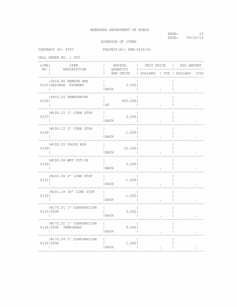
NEBRASKA DEPARTMENT OF ROADS PAGE: 13 DATE: 09/15/14 SCHEDULE OF ITEMS CONTRACT ID: 4707 PROJECT(S): URB-5436(5) CALL ORDER NO. : 450 ------------------------------------------------------------------------------- LINE| ITEM | APPROX. | UNIT PRICE | BID AMOUNT NO | DESCRIPTION | QUANTITY |----------------|-------------- | | AND UNITS | DOLLARS | CTS | DOLLARS |CTS ------------------------------------------------------------------------------- |3010.46 REMOVE AND | | | 0125|SALVAGE HYDRANT | 3.000| | | |EACH | . | . ------------------------------------------------------------------------------- |4910.25 DEWATERING | | | 0126| | 405.000| | | |LF | . | . ------------------------------------------------------------------------------- |W100.11 1" CURB STOP | | | 0127| | 3.000| | | |EACH | . | . ------------------------------------------------------------------------------- |W100.12 2" CURB STOP | | | 0128| | 1.000| | | |EACH | . | . ------------------------------------------------------------------------------- |W100.25 VALVE BOX | | | 0129| | 10.000| | | |EACH | . | . ------------------------------------------------------------------------------- |W100.56 WET CUT-IN | | | 0130| | 3.000| | | |EACH | . | . ------------------------------------------------------------------------------- |W101.06 6" LINE STOP | | | 0131| | 1.000| | | |EACH | . | . ------------------------------------------------------------------------------- |W101.18 18" LINE STOP | | | 0132| | 1.000| | | |EACH | . | . ------------------------------------------------------------------------------- |W175.01 1" CORPORATION | | | 0133|STOP | 3.000| | | |EACH | . | . ------------------------------------------------------------------------------- |W175.01 1" CORPORATION | | | 0134|STOP TEMPORARY | 9.000| | | |EACH | . | . ------------------------------------------------------------------------------- |W175.09 2" CORPORATION | | | 0135|STOP | 1.000| | | |EACH | . | . -------------------------------------------------------------------------------

NEBRASKA DEPARTMENT OF ROADS PAGE: 14 DATE: 09/15/14 SCHEDULE OF ITEMS CONTRACT ID: 4707 PROJECT(S): URB-5436(5) CALL ORDER NO. : 450 ------------------------------------------------------------------------------- LINE| ITEM | APPROX. | UNIT PRICE | BID AMOUNT NO | DESCRIPTION | QUANTITY |----------------|-------------- | | AND UNITS | DOLLARS | CTS | DOLLARS |CTS ------------------------------------------------------------------------------- |W176.26 1" WATER SERVICE | | | 0136| | 35.000| | | |LF | . | . ------------------------------------------------------------------------------- |W176.30 2" WATER SERVICE | | | 0137| | 70.000| | | |LF | . | . ------------------------------------------------------------------------------- |W176.54 WATER SERVICE | | | 0138|TEMPORARY | 1.000| | | |EACH | . | . ------------------------------------------------------------------------------- |W200.04 DUCTILE IRON | | | 0139|FITTINGS, M.J. | 5275.000| | | |LB | . | . ------------------------------------------------------------------------------- |W205.04 4" WATER MAIN | | | 0140|PIPE D.I. | 70.000| | | |LF | . | . ------------------------------------------------------------------------------- |W205.06 6" WATER MAIN | | | 0141|PIPE D.I. | 156.000| | | |LF | . | . ------------------------------------------------------------------------------- |W205.08 8" WATER MAIN | | | 0142|PIPE RESTRAINED D.I. | 100.000| | | |LF | . | . ------------------------------------------------------------------------------- |W205.12 12" WATER MAIN | | | 0143|PIPE RESTRAINED D.I. | 205.000| | | |LF | . | . ------------------------------------------------------------------------------- |W205.65 12" WATER MAIN | | | 0144|RESTRAIN JOINT D.I. | 100.000| | | |LF | . | . ------------------------------------------------------------------------------- |W219.66 6" GATE VALVE | | | 0145|AND BOX | 2.000| | | |EACH | . | . ------------------------------------------------------------------------------- |W221.97 FIRE HYDRANT | | | 0146| | 3.000| | | |EACH | . | . -------------------------------------------------------------------------------

NEBRASKA DEPARTMENT OF ROADS PAGE: 15 DATE: 09/15/14 SCHEDULE OF ITEMS CONTRACT ID: 4707 PROJECT(S): URB-5436(5) CALL ORDER NO. : 450 ------------------------------------------------------------------------------- LINE| ITEM | APPROX. | UNIT PRICE | BID AMOUNT NO | DESCRIPTION | QUANTITY |----------------|-------------- | | AND UNITS | DOLLARS | CTS | DOLLARS |CTS ------------------------------------------------------------------------------- |W221.97 FIRE HYDRANT | | | 0147|ASSEMBLY | 3.000| | | |EACH | . | . ------------------------------------------------------------------------------- |W350.39 18" X 6" TAPPING | | | 0148|SLEEVE AND VALVE | 2.000| | | |EACH | . | . ------------------------------------------------------------------------------- |W350.46 18" X 12" | | | 0149|TAPPING SLEEVE AND VALVE | 3.000| | | |EACH | . | . ------------------------------------------------------------------------------- |W350.47 18" X 4" TAPPING | | | 0150|SLEEVE AND VALVE | 1.000| | | |EACH | . | . ------------------------------------------------------------------------------- |W350.48 18" X 8" TAPPING | | | 0151|SLEEVE AND VALVE | 1.000| | | |EACH | . | . ------------------------------------------------------------------------------- |W725.00 RECONNECT WATER | | | 0152|SERVICE | 4.000| | | |EACH | . | . ------------------------------------------------------------------------------- |W750.11 TAPPING FIRE | | | 0153|HYDRANT ASSEMBLY | 2.000| | | |EACH | . | . ------------------------------------------------------------------------------- |W800.05 REMOVE GATE | | | 0154|VALVE AND BOX | 6.000| | | |EACH | . | . ------------------------------------------------------------------------------- |W800.21 REMOVE WATER | | | 0155|MAIN PIPE | 1056.000| | | |LF | . | . ------------------------------------------------------------------------------- |W800.25 REMOVE POST | | | 0156|INDICATOR VALVE | 1.000| | | |EACH | . | . ------------------------------------------------------------------------------- |W910.00 TEMPORARY | | | 0157|CORPORATION STOP | 4.000| | | |EACH | . | . ------------------------------------------------------------------------------- | | | SECTION 0004 TOTAL | . -------------------------------------------------------------------------------

NEBRASKA DEPARTMENT OF ROADS PAGE: 16 DATE: 09/15/14 SCHEDULE OF ITEMS CONTRACT ID: 4707 PROJECT(S): URB-5436(5) CALL ORDER NO. : 450 ------------------------------------------------------------------------------- LINE| ITEM | APPROX. | UNIT PRICE | BID AMOUNT NO | DESCRIPTION | QUANTITY |----------------|-------------- | | AND UNITS | DOLLARS | CTS | DOLLARS |CTS ------------------------------------------------------------------------------- SECTION 0005 GROUP 4B SANITARY SEWER ------------------------------------------------------------------------------- |0030.40 MOBILIZATION | | | 0158| |LUMP |LUMP | | | | | . ------------------------------------------------------------------------------- |4048.53 RECONSTRUCT 2" | | | 0159|SANITARY SEWER FORCE | 113.000| | |MAIN |LF | . | . ------------------------------------------------------------------------------- |4732.15 15" P.V.C. | | | 0160|SANITARY SEWER PIPE | 85.000| | | |LF | . | . ------------------------------------------------------------------------------- |4732.16 15" P.V.C. | | | 0161|SANITARY SEWER PLUG | 1.000| | | |EACH | . | . ------------------------------------------------------------------------------- |4732.18 18" P.V.C. | | | 0162|SANITARY SEWER PIPE | 136.000| | | |LF | . | . ------------------------------------------------------------------------------- |4732.19 18" P.V.C. | | | 0163|SANITARY SEWER PLUG | 1.000| | | |EACH | . | . ------------------------------------------------------------------------------- |4732.21 21" P.V.C. | | | 0164|SANITARY SEWER PIPE | 105.000| | | |LF | . | . ------------------------------------------------------------------------------- |4732.22 21" P.V.C. | | | 0165|SANITARY SEWER PLUG | 1.000| | | |EACH | . | . ------------------------------------------------------------------------------- |4741.12 12" FORCE MAIN | | | 0166|(D.I.) | 30.000| | | |LF | . | . ------------------------------------------------------------------------------- |4910.25 DEWATERING | | | 0167| | 326.000| | | |LF | . | . -------------------------------------------------------------------------------

NEBRASKA DEPARTMENT OF ROADS PAGE: 17 DATE: 09/15/14 SCHEDULE OF ITEMS CONTRACT ID: 4707 PROJECT(S): URB-5436(5) CALL ORDER NO. : 450 ------------------------------------------------------------------------------- LINE| ITEM | APPROX. | UNIT PRICE | BID AMOUNT NO | DESCRIPTION | QUANTITY |----------------|-------------- | | AND UNITS | DOLLARS | CTS | DOLLARS |CTS ------------------------------------------------------------------------------- |W100.56 WET CUT-IN | | | 0168| | 1.000| | | |EACH | . | . ------------------------------------------------------------------------------- |W200.04 DUCTILE IRON | | | 0169|FITTINGS, M.J. | 1025.000| | | |LB | . | . ------------------------------------------------------------------------------- |W800.09 REMOVE PLUG | | | 0170| | 3.000| | | |EACH | . | . ------------------------------------------------------------------------------- | | | SECTION 0005 TOTAL | . ------------------------------------------------------------------------------- SECTION 0006 GROUP 5 SEEDING ------------------------------------------------------------------------------- |0030.50 MOBILIZATION | | | 0171| |LUMP |LUMP | | | | | . ------------------------------------------------------------------------------- |L001.03 SEEDING, TYPE C | | | 0172| | 5.000| | | |ACRE | . | . ------------------------------------------------------------------------------- |L032.80 HYDROMULCH | | | 0173| | 8.000| | | |TON | . | . ------------------------------------------------------------------------------- | | | SECTION 0006 TOTAL | . ------------------------------------------------------------------------------- SECTION 0007 GROUP 8B ELECTRICAL ------------------------------------------------------------------------------- |0030.81 MOBILIZATION | | | 0174| |LUMP |LUMP | | | | | . ------------------------------------------------------------------------------- |1116.02 REMOVE CABLE | | | 0175| | 1235.000| | | |LF | . | . -------------------------------------------------------------------------------

NEBRASKA DEPARTMENT OF ROADS PAGE: 18 DATE: 09/15/14 SCHEDULE OF ITEMS CONTRACT ID: 4707 PROJECT(S): URB-5436(5) CALL ORDER NO. : 450 ------------------------------------------------------------------------------- LINE| ITEM | APPROX. | UNIT PRICE | BID AMOUNT NO | DESCRIPTION | QUANTITY |----------------|-------------- | | AND UNITS | DOLLARS | CTS | DOLLARS |CTS ------------------------------------------------------------------------------- |1136.04 REMOVE | | | 0176|DETECTION CAMERA | 1.000| | | |EACH | . | . ------------------------------------------------------------------------------- |7320.50 STREET NAME SIGN | | | 0177| | 6.000| | | |EACH | . | . ------------------------------------------------------------------------------- |7390.02 RELOCATE SIGN | | | 0178| | 1.000| | | |EACH | . | . ------------------------------------------------------------------------------- |A001.05 PULL BOX, TYPE | | | 0179|PB-2 | 12.000| | | |EACH | . | . ------------------------------------------------------------------------------- |A001.12 PULL BOX, TYPE | | | 0180|PB-5 | 54.000| | | |EACH | . | . ------------------------------------------------------------------------------- |A001.16 PULL BOX, TYPE | | | 0181|PB-6 | 1.000| | | |EACH | . | . ------------------------------------------------------------------------------- |A001.35 PULL BOX, TYPE | | | 0182|FOR-27 | 6.000| | | |EACH | . | . ------------------------------------------------------------------------------- |A001.36 PULL BOX, TYPE | | | 0183|FOT-48 | 4.000| | | |EACH | . | . ------------------------------------------------------------------------------- |A001.58 SPLICE CONDUIT | | | 0184| | 3.000| | | |EACH | . | . ------------------------------------------------------------------------------- |A002.35 GPS SIGNAL | | | 0185|PREEMPTION SYSTEM | 3.000| | | |EACH | . | . ------------------------------------------------------------------------------- |A003.10 TRAFFIC SIGNAL, | | | 0186|TYPE TS-1 , T36 | 14.000| | | |EACH | . | . -------------------------------------------------------------------------------

NEBRASKA DEPARTMENT OF ROADS PAGE: 19 DATE: 09/15/14 SCHEDULE OF ITEMS CONTRACT ID: 4707 PROJECT(S): URB-5436(5) CALL ORDER NO. : 450 ------------------------------------------------------------------------------- LINE| ITEM | APPROX. | UNIT PRICE | BID AMOUNT NO | DESCRIPTION | QUANTITY |----------------|-------------- | | AND UNITS | DOLLARS | CTS | DOLLARS |CTS ------------------------------------------------------------------------------- |A003.20 TRAFFIC SIGNAL, | | | 0187|TYPE TS-1A , T31 | 6.000| | | |EACH | . | . ------------------------------------------------------------------------------- |A004.15 TRAFFIC SIGNAL, | | | 0188|TYPE TS-1B , T3X | 4.000| | | |EACH | . | . ------------------------------------------------------------------------------- |A004.22 TRAFFIC SIGNAL, | | | 0189|TYPE TS-1LB , T49 | 5.000| | | |EACH | . | . ------------------------------------------------------------------------------- |A005.50 TRAFFIC SIGNAL | | | 0190|CONTROLLER, TYPE NEMA | 2.000| | | |EACH | . | . ------------------------------------------------------------------------------- |A006.14 PEDESTRIAN | | | 0191|SIGNAL, TYPE PS-1 , T19 | 18.000| | | |EACH | . | . ------------------------------------------------------------------------------- |A006.70 PEDESTRIAN | | | 0192|PUSHBUTTON, TYPE PPB | 18.000| | | |EACH | . | . ------------------------------------------------------------------------------- |A006.84 PEDESTAL POLE, | | | 0193|TYPE PP-10 | 3.000| | | |EACH | . | . ------------------------------------------------------------------------------- |A007.75 STREET LIGHTING | | | 0194|UNIT, TYPE SL-D-40-12-0. | 45.000| | |40 |EACH | . | . ------------------------------------------------------------------------------- |A007.78 STREET LIGHTING | | | 0195|UNIT, TYPE SL-D-30-12-0. | 7.000| | |40 |EACH | . | . ------------------------------------------------------------------------------- |A010.07 LUMINAIRE, TYPE | | | 0196|HPS-400 | 11.000| | | |EACH | . | . ------------------------------------------------------------------------------- |A011.24 COMBINATION MAST | | | 0197|ARM SIGNAL AND LIGHTING | 1.000| | |POLE, TYPE CMP-30-12 |EACH | . | . -------------------------------------------------------------------------------

NEBRASKA DEPARTMENT OF ROADS PAGE: 20 DATE: 09/15/14 SCHEDULE OF ITEMS CONTRACT ID: 4707 PROJECT(S): URB-5436(5) CALL ORDER NO. : 450 ------------------------------------------------------------------------------- LINE| ITEM | APPROX. | UNIT PRICE | BID AMOUNT NO | DESCRIPTION | QUANTITY |----------------|-------------- | | AND UNITS | DOLLARS | CTS | DOLLARS |CTS ------------------------------------------------------------------------------- |A011.65 COMBINATION MAST | | | 0198|ARM SIGNAL AND LIGHTING | 3.000| | |POLE, TYPE CMP-40-12 (NO |EACH | | |MAST ARM) | | . | . ------------------------------------------------------------------------------- |A012.05 COMBINATION MAST | | | 0199|ARM SIGNAL AND LIGHTING | 1.000| | |POLE, TYPE CMP-45-12 |EACH | . | . ------------------------------------------------------------------------------- |A012.08 COMBINATION MAST | | | 0200|ARM SIGNAL AND LIGHTING | 1.000| | |POLE, TYPE CMP-45-12 (NO |EACH | | |MAST ARM) | | . | . ------------------------------------------------------------------------------- |A012.60 COMBINATION MAST | | | 0201|ARM SIGNAL AND LIGHTING | 3.000| | |POLE, TYPE CMP-50-12 |EACH | . | . ------------------------------------------------------------------------------- |A012.80 COMBINATION MAST | | | 0202|ARM SIGNAL AND LIGHTING | 1.000| | |POLE, TYPE CMP-55-12 |EACH | . | . ------------------------------------------------------------------------------- |A012.90 COMBINATION MAST | | | 0203|ARM SIGNAL AND LIGHTING | 1.000| | |POLE, TYPE CMP-60-12 |EACH | . | . ------------------------------------------------------------------------------- |A014.76 SERVICE METER | | | 0204|AND PEDESTAL | 2.000| | | |EACH | . | . ------------------------------------------------------------------------------- |A016.50 MAST ARM SIGNAL | | | 0205|POLE, TYPE MP-30 | 1.000| | | |EACH | . | . ------------------------------------------------------------------------------- |A020.75 LIGHTING CONTROL | | | 0206|CENTER | 2.000| | | |EACH | . | . ------------------------------------------------------------------------------- |A070.13 2-INCH CONDUIT | | | 0207|IN TRENCH | 23297.000| | | |LF | . | . -------------------------------------------------------------------------------

NEBRASKA DEPARTMENT OF ROADS PAGE: 21 DATE: 09/15/14 SCHEDULE OF ITEMS CONTRACT ID: 4707 PROJECT(S): URB-5436(5) CALL ORDER NO. : 450 ------------------------------------------------------------------------------- LINE| ITEM | APPROX. | UNIT PRICE | BID AMOUNT NO | DESCRIPTION | QUANTITY |----------------|-------------- | | AND UNITS | DOLLARS | CTS | DOLLARS |CTS ------------------------------------------------------------------------------- |A070.18 3-INCH CONDUIT | | | 0208|IN TRENCH | 198.000| | | |LF | . | . ------------------------------------------------------------------------------- |A072.14 2-INCH CONDUIT | | | 0209|UNDER ROADWAY | 1840.000| | | |LF | . | . ------------------------------------------------------------------------------- |A074.90 CAT5E ETHERNET | | | 0210|CABLE | 5669.000| | | |LF | . | . ------------------------------------------------------------------------------- |A077.18 7/C #14 AWG | | | 0211|TRAFFIC SIGNAL CABLE | 5739.000| | | |LF | . | . ------------------------------------------------------------------------------- |A077.22 12/C #14 AWG | | | 0212|TRAFFIC SIGNAL CABLE | 127.000| | | |LF | . | . ------------------------------------------------------------------------------- |A077.30 20/C #14 AWG | | | 0213|TRAFFIC SIGNAL CABLE | 991.000| | | |LF | . | . ------------------------------------------------------------------------------- |A079.06 CAMERA DETECTOR | | | 0214|CABLE | 686.000| | | |LF | . | . ------------------------------------------------------------------------------- |A079.26 24 STRAND SINGLE | | | 0215|MODE FIBER | 6020.000| | | |LF | . | . ------------------------------------------------------------------------------- |A079.36 3/C #14 AWG, | | | 0216|PEDESTRIAN PUSH BUTTON | 1671.000| | |CABLE |LF | . | . ------------------------------------------------------------------------------- |A079.43 #8 GROUNDING | | | 0217|CONDUCTOR | 681.000| | | |LF | . | . ------------------------------------------------------------------------------- |A079.55 SERVICE CABLE | | | 0218|#6 | 168.000| | | |LF | . | . -------------------------------------------------------------------------------

NEBRASKA DEPARTMENT OF ROADS PAGE: 22 DATE: 09/15/14 SCHEDULE OF ITEMS CONTRACT ID: 4707 PROJECT(S): URB-5436(5) CALL ORDER NO. : 450 ------------------------------------------------------------------------------- LINE| ITEM | APPROX. | UNIT PRICE | BID AMOUNT NO | DESCRIPTION | QUANTITY |----------------|-------------- | | AND UNITS | DOLLARS | CTS | DOLLARS |CTS ------------------------------------------------------------------------------- |A079.60 STREET LIGHTING | | | 0219|CABLE #6 | 502.000| | | |LF | . | . ------------------------------------------------------------------------------- |A080.04 STREET LIGHTING | | | 0220|CABLE, NO. 1/0 USE | 212.000| | | |LF | . | . ------------------------------------------------------------------------------- |A080.10 STREET LIGHTING | | | 0221|CABLE, NO. 2 USE | 10306.000| | | |LF | . | . ------------------------------------------------------------------------------- |A080.15 STREET LIGHTING | | | 0222|CABLE, NO. 4 USE | 12224.000| | | |LF | . | . ------------------------------------------------------------------------------- |A080.23 STREET LIGHTING | | | 0223|CABLE, NO. 6 BARE | 106.000| | | |LF | . | . ------------------------------------------------------------------------------- |A080.30 STREET LIGHTING | | | 0224|CABLE, NO. 8 BARE | 11265.000| | | |LF | . | . ------------------------------------------------------------------------------- |A610.00 REMOVE TRAFFIC | | | 0225|SIGNAL , COMPLETE | 1.000| | | |EACH | . | . ------------------------------------------------------------------------------- |A610.18 REMOVE | | | 0226|PEDESTRIAN SIGNAL HEAD | 4.000| | | |EACH | . | . ------------------------------------------------------------------------------- |A611.12 REMOVE | | | 0227|PEDESTRIAN PUSHBUTTON | 4.000| | | |EACH | . | . ------------------------------------------------------------------------------- |A630.20 REMOVE PULL BOX | | | 0228| | 2.000| | | |EACH | . | . ------------------------------------------------------------------------------- |A699.90 REMOVE | | | 0229|COMBINATION POLE AND | 2.000| | |FOUNDATION |EACH | . | . -------------------------------------------------------------------------------
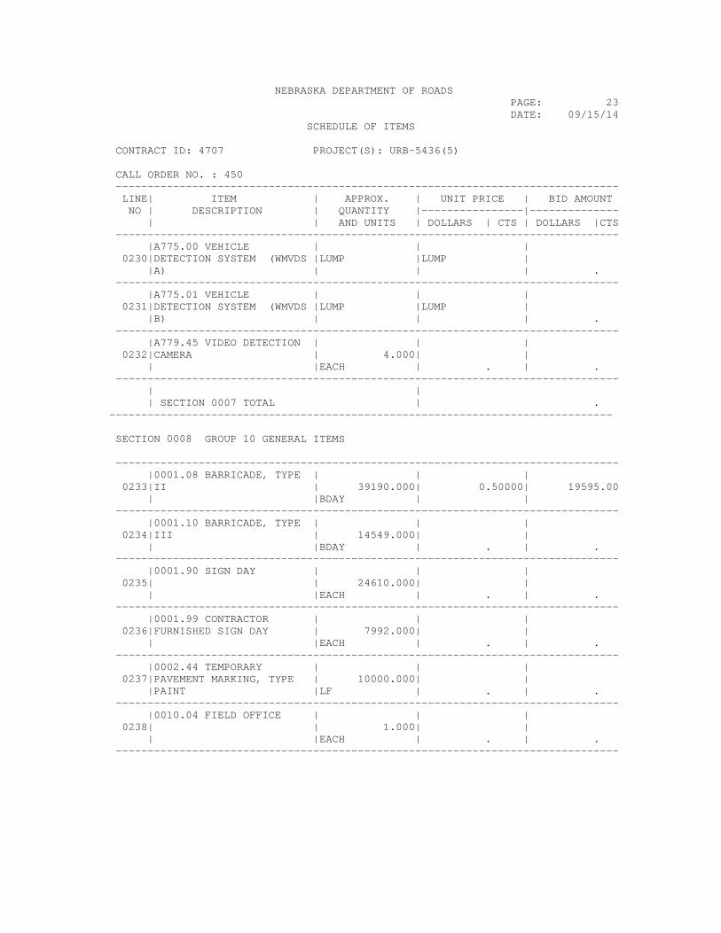
NEBRASKA DEPARTMENT OF ROADS PAGE: 23 DATE: 09/15/14 SCHEDULE OF ITEMS CONTRACT ID: 4707 PROJECT(S): URB-5436(5) CALL ORDER NO. : 450 ------------------------------------------------------------------------------- LINE| ITEM | APPROX. | UNIT PRICE | BID AMOUNT NO | DESCRIPTION | QUANTITY |----------------|-------------- | | AND UNITS | DOLLARS | CTS | DOLLARS |CTS ------------------------------------------------------------------------------- |A775.00 VEHICLE | | | 0230|DETECTION SYSTEM (WMVDS |LUMP |LUMP | |A) | | | . ------------------------------------------------------------------------------- |A775.01 VEHICLE | | | 0231|DETECTION SYSTEM (WMVDS |LUMP |LUMP | |B) | | | . ------------------------------------------------------------------------------- |A779.45 VIDEO DETECTION | | | 0232|CAMERA | 4.000| | | |EACH | . | . ------------------------------------------------------------------------------- | | | SECTION 0007 TOTAL | . ------------------------------------------------------------------------------- SECTION 0008 GROUP 10 GENERAL ITEMS ------------------------------------------------------------------------------- |0001.08 BARRICADE, TYPE | | | 0233|II | 39190.000| 0.50000| 19595.00 | |BDAY | | ------------------------------------------------------------------------------- |0001.10 BARRICADE, TYPE | | | 0234|III | 14549.000| | | |BDAY | . | . ------------------------------------------------------------------------------- |0001.90 SIGN DAY | | | 0235| | 24610.000| | | |EACH | . | . ------------------------------------------------------------------------------- |0001.99 CONTRACTOR | | | 0236|FURNISHED SIGN DAY | 7992.000| | | |EACH | . | . ------------------------------------------------------------------------------- |0002.44 TEMPORARY | | | 0237|PAVEMENT MARKING, TYPE | 10000.000| | |PAINT |LF | . | . ------------------------------------------------------------------------------- |0010.04 FIELD OFFICE | | | 0238| | 1.000| | | |EACH | . | . -------------------------------------------------------------------------------
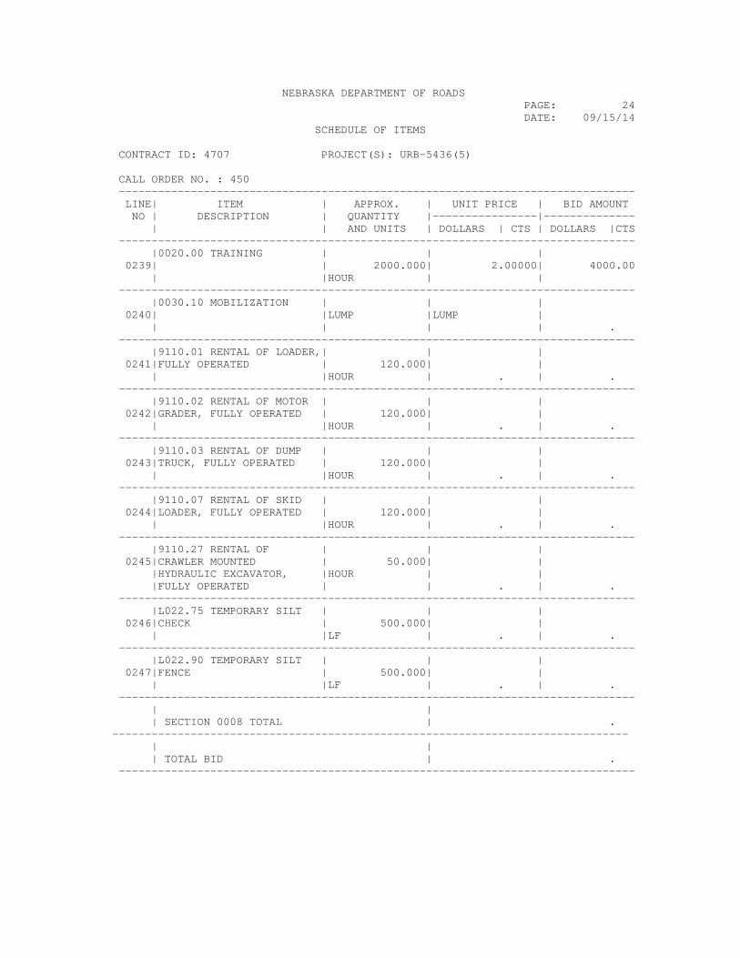
NEBRASKA DEPARTMENT OF ROADS PAGE: 24 DATE: 09/15/14 SCHEDULE OF ITEMS CONTRACT ID: 4707 PROJECT(S): URB-5436(5) CALL ORDER NO. : 450 ------------------------------------------------------------------------------- LINE| ITEM | APPROX. | UNIT PRICE | BID AMOUNT NO | DESCRIPTION | QUANTITY |----------------|-------------- | | AND UNITS | DOLLARS | CTS | DOLLARS |CTS ------------------------------------------------------------------------------- |0020.00 TRAINING | | | 0239| | 2000.000| 2.00000| 4000.00 | |HOUR | | ------------------------------------------------------------------------------- |0030.10 MOBILIZATION | | | 0240| |LUMP |LUMP | | | | | . ------------------------------------------------------------------------------- |9110.01 RENTAL OF LOADER,| | | 0241|FULLY OPERATED | 120.000| | | |HOUR | . | . ------------------------------------------------------------------------------- |9110.02 RENTAL OF MOTOR | | | 0242|GRADER, FULLY OPERATED | 120.000| | | |HOUR | . | . ------------------------------------------------------------------------------- |9110.03 RENTAL OF DUMP | | | 0243|TRUCK, FULLY OPERATED | 120.000| | | |HOUR | . | . ------------------------------------------------------------------------------- |9110.07 RENTAL OF SKID | | | 0244|LOADER, FULLY OPERATED | 120.000| | | |HOUR | . | . ------------------------------------------------------------------------------- |9110.27 RENTAL OF | | | 0245|CRAWLER MOUNTED | 50.000| | |HYDRAULIC EXCAVATOR, |HOUR | | |FULLY OPERATED | | . | . ------------------------------------------------------------------------------- |L022.75 TEMPORARY SILT | | | 0246|CHECK | 500.000| | | |LF | . | . ------------------------------------------------------------------------------- |L022.90 TEMPORARY SILT | | | 0247|FENCE | 500.000| | | |LF | . | . ------------------------------------------------------------------------------- | | | SECTION 0008 TOTAL | . ------------------------------------------------------------------------------- | | | TOTAL BID | . -------------------------------------------------------------------------------