Embed Size (px)
Citation preview

Information Technology 3 .
Corning Restricted .
.
Table of Contents
Registration and Login 2
Design Area Configuration: General 5
Cabinet: General 8
Build: General 14
Location 17
Tap/Tether 18
Preterm Lateral 19
Splice Planning 20
Additional Components 24
Component Summary 25
Messages 26
Specification Tree 28
Print Build Plans 30
Saving and Closing 32
Account Management 33
Creating Accounts 38
Labels 39

Information Technology 4 .
Corning Restricted .
.
Registration and Login
1. To have access to the configurator, please talk to your sales
representative and they will submit a ticket to get you registered.
2. Once your account has been set up, you will receive an email with
your login information and administrative rights.
3. From there, you will be able to register other employees from your
company.

Information Technology 5 .
Corning Restricted .
.
General
Design area information and default cable selection
Design Configuration
Product selection and configuration
Cabinet
Add builds and the option to select Cabinet, Splitter, and Closure
Splitter
Closure
Build
FlexNAP™ Assembly configuration
Location
Multiport
Tap/Tether
Drop

Information Technology 6 .
Corning Restricted .
.
Important Note: All options may vary based on
contract and design type. Your screen may
not be identical to the screenshots used in
this document.

Information Technology 7 .
Corning Restricted .
.
1. Design Areas: Choose appropriate Design Area from top of the
page. Design Area options may vary based on contract.

Information Technology 8 .
Corning Restricted .
.
Indoor Installation Types
Duct Cables that will be installed in ISP riser environments.
Tray Cables that will be installed in ISP riser environments.
Outdoor Installation Types
Aerial Cables that will be installed in aerial applications (overlash
or dedicated messenger).
Below Grade-Duct Cables that will be installed in buried duct applications
(1.25-in or >1.25-in duct capable).
Below Grade-Buried Cables that will be installed in direct buried
applications (trenching, plowing, missile bore, etc.) or in
2-in duct or larger.
Aerial-Duct Cables that will be installed in an aerial-duct
applications.
Self-Supporting Figure-8 cables with an attached messenger wire.
1. Description: Provide a description of the design area you are building. For
tracking purposes, keeping this information unique for each FlexNAP™ cable
designed is recommended.
2. Country, State/Region, City: Provide the geographical information for the design.
3. Project ID: Provide the project or work order number for the FlexNAP build being
designed. This information will print on the paperwork which ships with each
FlexNAP cable and will be printed on labels attached to the FlexNAP cable ends
and access points.
4. Environment type: Select what type of environment this build will be deployed in.
Options are: Outdoor; Indoor
5. Installation type: This drop-down menu automatically populates with
choices based on environment type.
Design Area
Reminder: These images may not match your
screen based on customer and previous
selections.

Information Technology 9 .
Corning Restricted .
.
6. Duct size: This field will only become available if “Below Grade-Duct” or
“Indoor Duct” is chosen as the installation type. The options for duct size
are: 1.25-in, >1.25 –in. This refers to inner diameter of the duct.
7. Armor type: Select if armored cable is needed. If it is needed, select
“Single”. If no armor is needed, select “N/A”. Only armored option is
single jacket, single armor.
8. Cable type: The options in this field will change based on the
environment and installation type chosen. The options are: Loose Tube,
RPX® Ribbon.
9. Fiber mode type: If the environment type is outdoors, this field will automatically
populate to “Single-Mode OS2”. If the environment type is indoors, the choices are:
Single-Mode OS2 , 50 µm multimode OM3
10. Buffer-tube Fill type: Select what buffer-tube fill type is needed. Depending on the
previous choices made, this may be automatically generated. All possible options
are: Gel-Free and Gel-Filled. Gel-filled is only offered on figure-8 cable type.
11. Flame retardant type: This will only become an option when an indoor environment
is chosen.
12. Support type: Select whether or not self-supporting option is needed . Our self-
supporting option is our figure-8 cable.
13. Toneable type: Select “Yes” if you would like toneable.
Design Area
These fields can be filled out at the global level
(current general field) or can be filled out at the
individual build level. All asterisks are present.
1.25 in
> 1.25in
Loose Tube
RPX® Ribbon

Information Technology 10 .
Corning Restricted .
.
Build fiber assignment methods
High to Low, CO to Field Spares: lowest fiber counts
Assigned Fibers: CO side higher-fiber counts, field
side lower-fiber counts
High to Low, Field to CO Spares: lowest fiber counts
Assigned Fibers: CO side lower-fiber counts, field
side higher-fiber counts
Low to High, CO to Field Spares: highest fiber counts
Assigned Fibers: CO side lower-fiber counts, field
side higher-fiber counts
Low to High, Field to CO Spares: highest fiber counts
Assigned fibers: CO side higher-fiber counts, field
side lower-fiber counts
Best Fit Fiber assignment based on ease of manufacturing
14. Build fiber assignment method: Select your fiber
assignment method. Options are: High to Low, CO to
Field; High to Low, Field to CO; Low to High, CO to
Field; Low to High, Field to CO; Best Fit (see table
right)
15. Length unit measure: Should automatically populate
to “Feet” or “Meters” based on customer
16. Contract customer - for internal customer use
Design Area

Information Technology 11 .
Corning Restricted .
.
1. Design Configuration: Select this box and you should see two boxes
drop-down; Cabinet and Additional Components. Select the “Cabinet”
tab to continue.
2. Cabinet Catalog number: This item is optional. If the
catalog number is known, choose from the drop-down
menu.
3. Do you want to add a cabinet to your design?:
Selection options: Yes; No. If planning to purchase a
cabinet with design, select Yes. Otherwise select, No- just
a placeholder.
4. How many builds do you want to add to your design?- Type in this
field the number of builds that are being added to this design. Enter this
value as a numerical figure (1,2,3 etc)
5. Add a build at a specific position in the cabinet: This will enable you
to add a build to a specific location.
6. Would you like to add an additional splitter?: To add additional
capacity, multiple splitters are often needed in the cabinet. Select “Yes”
to add an additional splitter. If choose “Yes”, reference page 12.
7. Would you like to add a closure to your design?: If
choose yes, reference page 13
Information Technology 12 .
Corning Restricted .
.
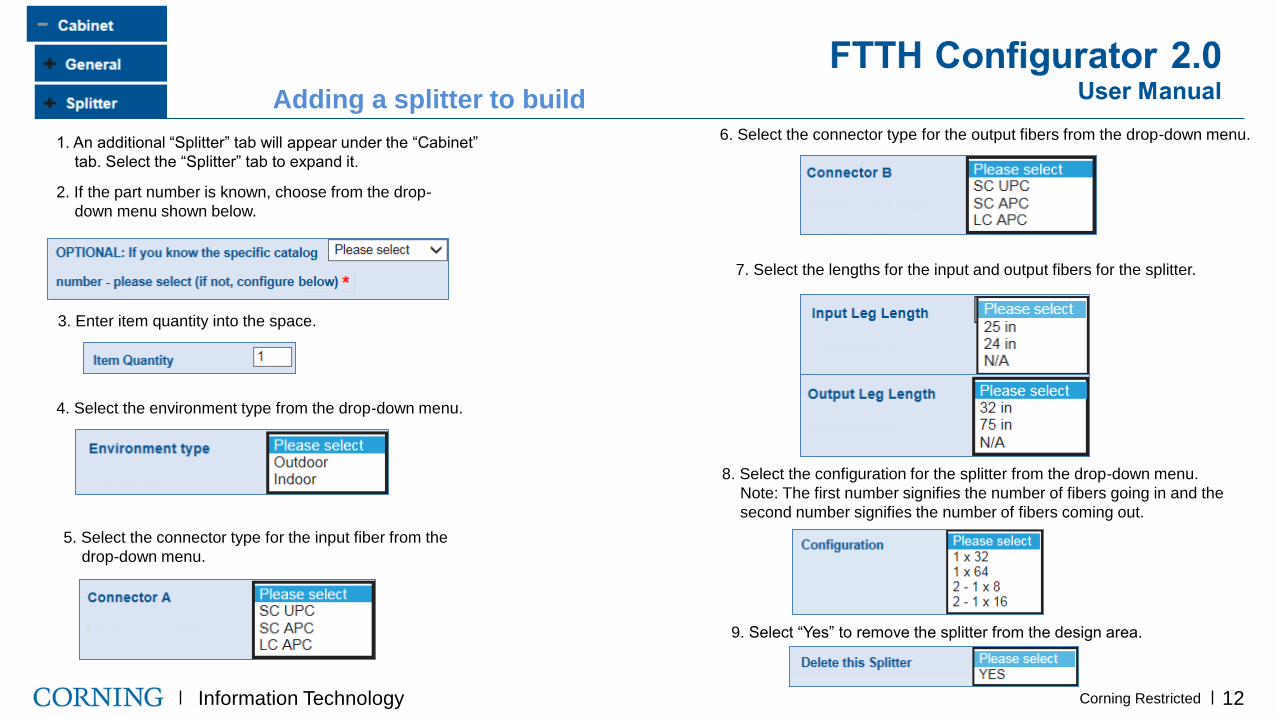
Adding a splitter to build
1. An additional “Splitter” tab will appear under the “Cabinet”
tab. Select the “Splitter” tab to expand it.
2. If the part number is known, choose from the drop-
down menu shown below.
3. Enter item quantity into the space.
4. The environment type, connector types, and input/output leg
lengths may be automatically generated based on previous
suggestions. If they are not, please fill out accordingly.
8. Select the configuration for the splitter from the drop-down menu.
Note: The first number signifies the number of fibers going in and the
second number signifies the number of fibers coming out.
9. Select “Yes” to remove the splitter from the design area.
4. Select the environment type from the drop-down menu.
5. Select the connector type for the input fiber from the
drop-down menu.
6. Select the connector type for the output fibers from the drop-down menu.
7. Select the lengths for the input and output fibers for the splitter.

Information Technology 13 .
Corning Restricted .
.
1. An additional “Closure” tab will appear under the “Cabinet”
tab. Select the “Closure” tab to expand it.
2. If the part number is known, choose from the drop-
down menu shown below.
3. Enter item quantity into the space.
4. Select “Yes” to remove the splitter from the design area.
Note: While other components of the build may
be configurable, the closures are not. A part
number must be known to add a closure to your
design area.
Adding a closure to build

Information Technology 16 .
Corning Restricted .
.
10. Autogenerate splice plan: More info on splice plan on pages 22-23.
By selecting yes, it will provide a splice plan of your FlexNAP™ builds to
the cabinet legs.
8. Port Count - Number of ports associated with the cabinet
selected
Leg Count - Number of output legs associated with the
cabinet selected
9. Add an additional cabinet to your DA: Select if more
than one cabinet is needed for this design area.
Note: When entering the build section, all boxes included in screen below may be automatically filled
based on previous inputs. The selections below are for an example and may not be identical to your build.
If you would not like to “Accept design area defaults” and would like to make different selections, select
“No” from the drop-down menu.
Note: Do not select “Yes” until all cables are configured.
Buffer tube Fill type *

Information Technology 17 .
Corning Restricted .
.
2. TAP type: Select what kind of TAP will be used. TAP types
available are: Overmold, Heat-shrink, Overmold (RPX®)
3. Build fiber assignment method: Fiber assignment methods
available are: High to Low, CO to Field; Low to High, Field to CO.
4. How many locations or additional locations do you want to
add?: Enter the number of locations (poles, pedistals, handholes)
that will be used in this build. This needs to be entered as a numerical
value.
5. CO Slack: the amount of slack requested on the wire center side (Central
Office, Headend, Hub, etc.) end of the FlexNAP™ System cable. This field
defaults to a minimum 50 ft.(15.24m) and can be overridden by the user. This
slack is typically used for splicing the FlexNAP System cable into the Hub or
Main Distribution network. This number can be changed to greater than 50 ft,
but not less than.
6. Field Slack: the amount of slack requested on the Field End of the FlexNA
System cable. This field defaults to 15 ft. (4.572 m) for Aerial/Tray and 25 ft.
(5m) for Buried/Duct. This is the minimum amount of slack required on the
Field End of the cable. This field can be overridden to accept longer lengths.
This number can be changed to greater than 15 ft, but not less than.
7. Preterm type: Select “CO-side” or none. If more information is
needed, please contact your sales person.
1. Fiber count: Select the fiber count of the distribution cable
Note: Reference page10 for more info on fiber assignment methods.
Overmold
Heatshrink
Overmold® RPX

Information Technology 18 .
Corning Restricted .
.
8. Select leg type. This is automatically generated. 4. Select Preterm on Build tab and then General tab
5. If the part number is known, select from the drop-down menu.
6. Select the type of connector being used for the preterm lateral
(12 or 24 fibers)
7. Furcation type for a preterm lateral should be automatically
generated. This means that the lateral has the tensile strength listed.
Preterm Lateral
Preterm Lateral: A preterm lateral is a way to connect an
additional FlexNAP™ cable to service a side street or cul-de-sac.
Pinless OptiTip® connectors are used to break off the main path
without having to splice in the additional cable.
Preterm on Build
Preterm on Build

Information Technology 19 .
Corning Restricted .
.
8. How many fibers do you want to express?- This is referring to
the fibers that will not be used during this distribution network but
will be saved for downstream use.
9. Start express fiber number: This is referring to the number of the
first fiber that will be expressed. It will be assumed that all fibers
after this number will be expressed.
12. Delete build: Select “Yes” to remove build from design area
10. Maximum allowable cable length: This is automatically
generated based on cable type and reel capacity.
11. Cable length- The current cable length based on all
entries in build configuration.
Note: See page 23 for splice plan information

Information Technology 20 .
Corning Restricted .
.
1. Location sequence: Automatically generated by configurator
2. Location ID: The name of the pole/handhole/pedestal as shown on
the design area. User-generated data field that will be printed on
tether labels.
3. Span-distance to next location: The distance between locations.
The unit of measure will be consistent with the “length unit measure”
selected under the general tab.
4. Slack storage: The additional slack footage that will be stored at this
location. This will be located on the field side of the location. This will
be designated by yellow stickers on the cable.
Note: This will automatically generate to 0.0 on the final location of the
build. If the final location is deleted, you will have to change the new
final location to 0.0.
5. Sag adder: the distance (no longer percentage based) of sag that will
be added to the span distance specified in aerial applications. The sag will
be added to the value of the span, entered above. We do not recommend
changing this value unless it is necessary. (Best practice is to leave this as
0)
6. Number of tethers at this location: Use the drop-down menu to select
the number of tethers that will be needed at this location. If not adding
tethers to the location, leave the field as “Please select”.
7. Position to move this location to: This will enable you to move the
location to a specific location sequence.
8. Delete location: Select “YES” to delete the location created.

Information Technology 21 .
Corning Restricted .
.
2. Tether fiber count: The number of fibers assigned to this
tether
1. Catalog Number (BEST PRACTICE): If you know the part
number, select from drop-down below. If this number is not
known, configure below.
3. Tether type: Select tether type from drop-down menu
4. Loop back: COC offers a loopback device contained within the OptiTip® MT
dust cap. The loop back allows a user to test the FlexNAP™ system cable for
continuity after installation and prior to terminal assemblies being installed at
the network access point (NAP) locations. If a loop back is desired at a NAP
location, select “Yes” in the loop back field.
5. Add a multiport: Select whether or not you would like to add a
multiport to this build. This will add the multiport to the final build of
materials for the design area.
7. Preterm lateral: Details in next slide
6. Leg length and UOM: length of the tether
Preterm Lateral: A preterm lateral is a way to connect an additional
FlexNAP cable to service a side street or cul-de-sac.
Pinless OptiTip® connectors are used to break off the main path
without having to splice in the additional cable.
Do you want to add a multiport?
ft
Information Technology 22 .
Corning Restricted .
.
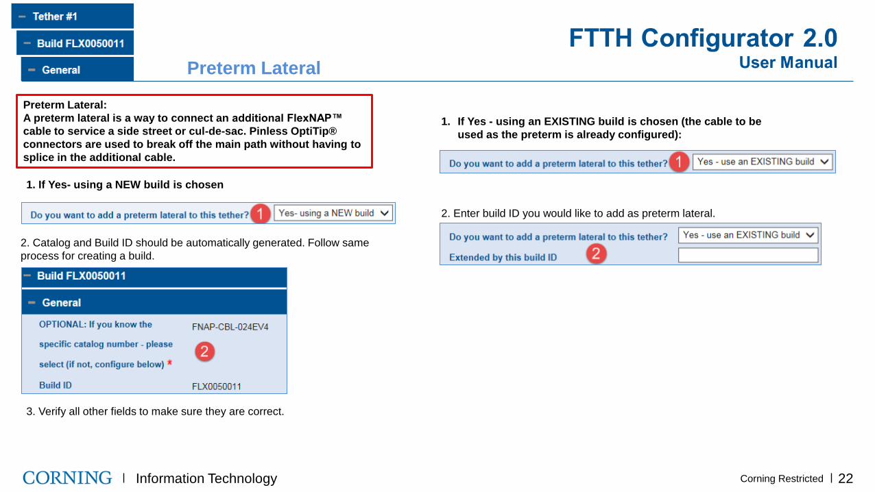
Preterm Lateral:
A preterm lateral is a way to connect an additional FlexNAP™
cable to service a side street or cul-de-sac. Pinless OptiTip®
connectors are used to break off the main path without having to
splice in the additional cable.
2. Catalog and Build ID should be automatically generated. Follow same
process for creating a build.
3. Verify all other fields to make sure they are correct.
1. If Yes- using a NEW build is chosen
1. If Yes - using an EXISTING build is chosen (the cable to be
used as the preterm is already configured):
2. Enter build ID you would like to add as preterm lateral.
Preterm Lateral

Information Technology 23 .
Corning Restricted .
.
1. Splice Plan- If splice plan generation is needed, navigate back to
General tab for the FlexNAP™ cable (under “Build ID” Ex. FLX0003055)
and scroll down to “Start Splice Planning” and select Yes.
Next- To Autogenerate splice plan for a particular cable
build, select “YES” if you would like to manually do the
splice plan, select “NO”
Note: Do not select “Yes” for splice
planning until entire cable is configured. 3. A tab will then appear that says “Fibers for Splice Plan”.
Select this tab to continue with splice plan.
Splice Plan

Information Technology 24 .
Corning Restricted .
.
1. When splice plan is generated, the fibers will be organized by tap.
2. Fiber assignment will be automatically generated based on previous
selection for fiber assignment method. Enter Port Number and FiberID
based on design.
Autogenerated (Best Practice)
Note: If a cabinet is being selected, the autogenerated splice plan will generate the
port numbers. (shown below)
Note: The FiberID will print on the build plans. This can be
named anything including numerics and letters.

Information Technology 25 .
Corning Restricted .
.
Manual Splice Plan (High-to-Low Selection)
Select the Tap Fibers tab, and the number of fibers chosen
per tap will appear below with everything else blank.
Select the fiber assignment for the first fiber listed, and the rest should
automatically generate.
Enter the Fiber IDs and Port Numbers manually for each fiber.
Note: The Fiber ID will print on the paperwork. This can
be named anything including numbers and letters/

Information Technology 26 .
Corning Restricted .
.
Manual Splice Plan (Best Fit)
1. Select the “Tap Fibers” tab.
2. Select the fiber assignment (i.e. Single/Blue/Blue) for each fiber.
3. All port numbers and Fiber IDs will need to be entered individually.
Note: The Fiber ID will print on the paperwork. This can
be named anything including numerics and letters.
Fiber ID

Information Technology 27 .
Corning Restricted .
.
1. Additional Components: Choose from the appropriate drop-
down menus to add additional components to the BOM.
If a Multiport is
added:
If a Drop is added:
SC APC OptiTap® connector

Information Technology 28 .
Corning Restricted .
.
1. Below Component Summary, click the “FlexNAP™ Build” tab and then
the “General” tab to view/validate the part number and details of the
FlexNAP build created.
If other components are added to the build, they will appear in the
component summary as well, and can be expanded for more details.
Below “FlexNAP Build” will be more details about cables and tethers
added to the design area. Continue to expand the tabs to view
cable/tether information.
Expanded:
FlexNAP Build
Number of locations
Number of locations tapped
Number of tethers
Number of fibers
Number of fibers planned
Component Quantity for display
Build ID
Length unit measure
OPTIONAL: If you know the specific catalog
number- please select (if not, configure
below)

Information Technology 29 .
Corning Restricted .
.
1. If there is an error in the build, it will appear in the
“Messages” tab.
2. When the “Error” tab is expanded, the Error Message will
appear at the bottom of the tab. These errors will need to be
corrected to complete the design area.
Note: See page 30 for possible messages.

Information Technology 30 .
Corning Restricted .
.
Error Messages Message: "Build has an error“- This build is incorrectly put together. It cannot be assembled as specified. Please correct this configuration
Message: "Exceeded build length limit" -You have exceeded the maximum cable length for selected cable
Message: "Exceeded build fiber count“- Number of assigned tether fibers exceeds Cable fiber count
Message: "Exceeded Cabinet fiber capacity" - Number of assigned tether fibers exceeds Cabinet Port count
Message: “CO Slack less than minimum“ - Central Office Slack less than minimum for installation type
Message: "Field Slack less than minimum" - Field Slack less than minimum for installation type
Message: "Tap accesses too many subunits" - too many subunits accessed for this tap type
Message: "Location ID must be unique" - Location ID not unique within this build
Message: "Do not enter a Span on the last location" - Span on last location is illogical
Message: "Build has unspliced tether fibers" - Build has unspliced tether fibers
Message: "Cannot plan Cabinet, unplanned builds" - Cannot plan Cabinet with Builds with unspliced tether fibers
Message: "Build has no tethers. At least 1 tether is required." - Build has no tethers. At least 1 tether is required.
Message: "There was an error in auto splice planning for your build"
Message: "Span less than mandatory minimum" - The span length you have specified is not permitted. It must be increased.
Message: "Build contains unorderable products" - Design area has products without an ERP Material number, therefore not orderable.
Message: "Design Area contains unorderable products": Design area has products without an ERP Material number, therefore not orderable.
Message: "Any other error message" - Cover message for any unspecific errors
Warning Messages Message: "Inner layer spliced first" - Your splice plan calls for assigning inner layer fibers first. Outer layer fibers will be unusable.
Message: "Preterm Build on tether < 12F“- Adding a Preterm build to a tether with less than 12 fibers is not recommended
Message: "Please select a larger fiber count for your cable” - It is physically impossible to plan all of your fibers into your selected cable. Please choose a cable with
more fibers.
Info Messages Message: "Specify locations" - You have specified a build. Please proceed by specifying its locations.
Message: "Span exceeds recommendations" - The span length you have specified is undesirable. We recommend a correction.
Message: "Specify tethers.- You can configure a location by specifying its required tethers.

Information Technology 31 .
Corning Restricted .
.
Specification Tree: This will appear on the right side of the screen. As
components are added to the design, they will appear on the tree.
Save: Click this throughout the design process to save the
design.
Cancel: Click Cancel to discard the design.
Once the design is saved, more options will appear:
Lock All Builds: This will lock all builds that are complete
and consistent.
Unlock All Builds: This will unlock all locked builds.
Review Design Area: Review all builds in the design area
to approve or reject that are complete and consistent.
Save: Select to save and continue working.
Save & Close: Select to save and close your design area.
Cancel: Select to cancel any unsaved data.
Delete: Select to Delete design area.
Navigating Specification Tree
Note: If a build has been
approved post review,
unlocking it will reset the
review.

Information Technology 32 .
Corning Restricted .
.
As locations/taps/components are added to the design area, they will show up on
the left side specification tree. Everything on the list is a hyperlink and if clicked
on, will bring you to that part of the design area as shown in the screenshots
below.
Note: The different levels of the
specification tree are all
expandable, so if you are not
seeing all aspects of the design
area, click the plus sign to
expand.
Navigating Specification Tree
Do you want to add a loop back? *
OptiTip® MT – Pinned

Information Technology 33 .
Corning Restricted .
.
Print Build Plans
1. Select “My Design Areas” in toolbar in the top right of your screen.
2. Select the name of the design area to view more options.
3. Select the “Print” button in the top right corner.
This will direct you to another page that allows you to print a summary of
your design area/BOM as shown below.
Project ID Test

Information Technology 34 .
Corning Restricted .
.
Print Build Plans
Select “Cabinet Splice Plan”, “Build Splice Plan,” and
“Cable Splice Plan” to view/print the respective splice plan.
Example of Cabinet Splice Plan:

Information Technology 35 .
Corning Restricted .
.
After saving and closing: After saving and closing, there will be a screen similar to below summarizing build and materials
needed. If something needs to be changed, you may select the edit to re-enter the design and make changes.
Saving and Closing

Information Technology 37 .
Corning Restricted .
.
1. In the navigation bar at the top of the screen, select “My Account”.
2. The screen below should appear.
3. In the profile section:
• Select “Update personal details to change your
name, email address, and phone number on
the account.
• Select “Change your password” to change the
password used to log into the configurator.
4. Select “Get order status” to be redirected to
Corning’s order tracking system.
5. Select “Manage your delivery addresses” to add/edit
delivery address options for account.
Account Management

Information Technology 38 .
Corning Restricted .
.
1. Select “Contact Us” on the top navigation bar to send a message or get in
contact with an administrator within COC.
2. Choose a subject and type a message in the text box to be sent to a
Corning Administrator.
3. Call the phone numbers below to get in
contact with a Corning Representative.
4. Email the address below to get in contact with
Corning’s Customer Care Department.
Account Management

Information Technology 39 .
Corning Restricted .
.
1. Select “My Design Areas” on the top navigation bar to see all design areas created
on the current account.
2. The design areas should appear below. Select “View” on the right-hand side to open the individual design area.
Select actual hyperlink to
get into dA and getting into
DA
Account Management

Information Technology 40 .
Corning Restricted .
.
1. Hover mouse over “your shopping cart” to receive a drop-down menu of
items in your cart. Select checkout to move forward with purchase.
Account Management

Information Technology 41 .
Corning Restricted .
.
1. Go to “My Company” in the toolbar in the top right corner of the screen.
2. Select “Add new users.”
3. Fill out form shown to the right. Select Role based on what the new user will be
using the configurator for and click “Save Updates.”
Creating Customer Accounts
Note: You must have administrative rights to create customer accounts.
FlexNAP™ Build Configuration Reviewer
FlexNAP Designer
FlexNAP Designer Supervisor
FlexNAP Build Configuration Uploader
FlexNAP Procurement
FlexNAP Company Account Administrator

Information Technology 42 .
Corning Restricted .
.
Data Description Source
AAAAAAAAAA Corning Internal Build ID COC Internal
111 Location Sequence Configurator
BBBBBBBBBBBBBBBBBB Location ID Configurator
CCCCCCCCCCCCCCCC Label Type COC Internal
222,222 Approx Length Mark on Cable
Jacket of Label
Configurator/COC
Internal
DDDDDD Cable Length Marking UOM COC Internal
Data Description Source
EEEEEEEEEE Cable Name or Apical MTP
Number
Configurator/COC
Internal
333-444 Lowest Port Number Value-
Highest Port Number Value for
Tether or Apical MTP
Configurator
AAAAAAAAAAA Corning Internal Build ID COC Internal
FFFFFFFFFFFFFFFFFFFF Location ID or PreTerm Terminal ID Configurator/COC
Internal
LOC 111- TAP 555 Tap Sequence at Specified
Location
Configurator
THR 777 Tether Sequence at Specified
Location/TAP
Configurator
Labels