Embed Size (px)
Citation preview

100 Deflection
F: –294 N
F: +294 N
Coil scrapers
Offset Pin Shift Cylinderwith high rigidity offset load capacityø32, ø40, ø50High rigidity, High precisionWith plate extended:
Deflection of ±0.1 mm or less(For ø50, 25 mm stroke, when allowable moment 29.4 N·m is applied)
�3 different port location directions can be selected.
Auto switches are mountable.�Coil scrapers equipped as standard
Offset pin shift cylinder
Port location A Port location B
Port location C
Application Example
Applicable Auto Switches:• �Magnetic field-resistant solid state auto switch:
D-P3DWA, D-P4DW• Small auto switch:
D-M9, D-A9
The D-P3DWA, D-M9, and D-A9 are mountable on 3 surfaces.
* The D-P4DW is mountable on 2 surfaces.
Mounting A Mounting BCylinder mounting bolt(Provided by customer)
Equipment
Can be mounted from 2 directions
INFORMATION
CDQ2B-X283916-E676

Offset Pin Shift Cylinder
CDQ2B-X2839ø32, ø40, ø50
A40 50 P3DWAZ
How to Order
X2839Offset pin shift cylinderBuilt-in magnet
for auto switch
Bore size32 32 mm40 40 mm50 50 mm
Stroke [mm]Bore size Stroke
32 25, 5040 25, 50, 7550 25, 50, 75 Auto switch
Nil Without auto switch
Select applicable auto switch models from the table below.
Number of auto switchesNil 2S 1
Auto Switch Models: Refer to the Best Pneumatics Catalog for further information on auto switches.
Magnetic Field-resistant Auto Switches
Type Auto switch model
Applicablemagnetic field Electrical entry Indicator
lightWiring
(Pin no. in use)Load
voltageLead wire
lengthApplicable
load
Solid state auto switch
D-P3DWASC
AC magnetic field (Single-phaseAC welding
magnetic field)
Pre-wired connector
2-color indicator
2-wire (3−4)
24 VDC
0.3 m
Relay, PLC
D-P3DWASE 2-wire (1−4)D-P3DWA
Grommet 2-wire0.5 m
D-P3DWAL 3 mD-P3DWAZ 5 mP4DWSC
Pre-wired connector2-wire (3−4)
0.3 mP4DWSE 2-wire (1−4)P4DWL
Grommet 2-wire3 m
P4DWZ 5 m
Small Auto Switches Small auto switches cannot be used under a strong magnetic field.
Type Special function
Electrical entry
Indica
tor lig
ht
Wiring (Output)
Load voltage Auto switch model Lead wire length [m]Pre-wired connector Applicable load
DC AC Perpendicular In-line 0.5(Nil)
1(M)
3(L)
5(Z)
So
lid s
tate
au
to s
wit
ch
—
Grommet Yes
3-wire (NPN)
24 V
5 V, 12 V
—
M9NV M9N IC circuit
Relay, PLC
3-wire (PNP) M9PV M9P 2-wire 12 V M9BV M9B —
Diagnostic indication (2-color indicator)
3-wire (NPN)5 V, 12 V
M9NWV M9NW IC circuit
3-wire (PNP) M9PWV M9PW 2-wire 12 V M9BWV M9BW —
Water resistant (2-color indicator)
3-wire (NPN)5 V, 12 V
M9NAV M9NA IC circuit
3-wire (PNP) M9PAV M9PA 2-wire 12 V M9BAV M9BA —
Ree
d
auto
sw
itch
— GrommetYes
3-wire (NPN equivalent) — 5 V — A96V A96 — — — IC circuit —
2-wire 24 V12 V 100 V A93V*1 A93 — — Relay,
PLCNo 5 V, 12 V 100 V or less A90V A90 — — — IC circuit*1 The 1 m lead wire is only applicable to the D-A93.* Solid state auto switches marked with “” are produced upon receipt of order.* Auto switches and mounting brackets are shipped together, but not assembled.
* Lead wire length symbols: 0.5 m······Nil (Example) M9NWV 1 m······ M (Example) M9NWVM 3 m······ L (Example) M9NWVL 5 m······ Z (Example) M9NWVZ
Port locationA B C
C directionB direction
A direction
C D Q2B
1
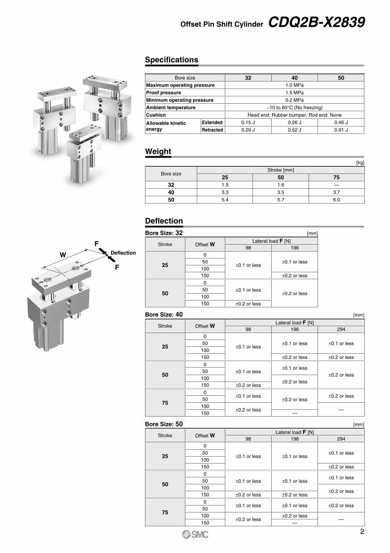
W Deflection
F
F
Offset Pin Shift Cylinder CDQ2B-X2839
Specifications
Bore size 32 40 50Maximum operating pressure 1.0 MPa
Proof pressure 1.5 MPa
Minimum operating pressure 0.2 MPa
Ambient temperature −10 to 60°C (No freezing)
Cushion Head end: Rubber bumper, Rod end: None
Allowable kinetic energy
Extended 0.15 J 0.26 J 0.46 J
Retracted 0.29 J 0.52 J 0.91 J
Weight[kg]
Bore sizeStroke [mm]
25 50 7532 1.5 1.6 —
40 3.3 3.5 3.7
50 5.4 5.7 6.0
DeflectionBore Size: 32 [mm]
Stroke Offset WLateral load F [N]
98 196
25
0
±0.1 or less±0.1 or less50
100150 ±0.2 or less
50
0±0.1 or less
±0.2 or less50100150 ±0.2 or less
Bore Size: 40 [mm]
Stroke Offset WLateral load F [N]
98 196 294
25
0
±0.1 or less±0.1 or less ±0.1 or less50
100150 ±0.2 or less ±0.2 or less
50
0±0.1 or less
±0.1 or less±0.2 or less
50100
±0.2 or less150 ±0.2 or less
75
0±0.1 or less
±0.2 or less±0.2 or less
50100
±0.2 or less —150 —
Bore Size: 50 [mm]
Stroke Offset WLateral load F [N]
98 196 294
25
0
±0.1 or less ±0.1 or less±0.1 or less50
100150 ±0.2 or less
50
0±0.1 or less ±0.1 or less
±0.1 or less50100
±0.2 or less150 ±0.2 or less ±0.2 or less
75
0±0.1 or less ±0.1 or less ±0.2 or less
50100
±0.2 or less±0.2 or less
—150 —
2

The above figure shows the condition when a stroke is extended.
HU
VW
Y
KAC + Stroke
PA
±0.0
5
øDK
(A + Stroke)
B + StrokeXFC
FA FB PC PB
PA
TZ
R
G±0.05
SL
JA±0.5
(FC + Stroke) ±0.2
Q F
E
R±0
.05
J
2 x P(Port)
Coil scrapers (equipped in 3 locations)
RA
±0.4
5
(øX
AH
7 ho
le p
itch)
4 x JJ through
2 x øXAH7 depth XC
2 x 4 x øOB counterbore depth OL4 x øOA through
MM depth M
(N)
2 x 2 x øXAH7 depth XB
CDQ2B-X2839
Dimensions
[mm]
Bore size Stroke A B C D E F FA FB FC G H J JA JJ K KA L M MM N
32 25, 50 102 33 10 20 45 7.5 13 8 45 46 109 7 23 M6 x 1.0 17 4.5 30 12 M8 x 1.25 5
4025, 50, 75
128.5 39.5 10 25 52 7.5 18 11 60 53 137 8.5 26.5 M8 x 1.25 22 5 34 15 M10 x 1.5 5
50 144.5 40.5 10 32 64 10.5 21 15 70 65 160 10 32.5 M10 x 1.5 27 6 40 15 M10 x 1.5 5
Bore size Stroke OA OB OL P PA PB PC Q R RA S T U V W X XA XB XC Y Z
32 25, 50 6.4 11 16.5 Rc1/8 55 30 9 10 90 10 44 104 55 34.5 49.5 48 6 12 8 22.5 10
4025, 50, 75
9 14 8.6 Rc1/8 70 40 11 12.5 110 15 51 127 75 41 57 60 8 15 10 36.5 15
50 11 17 11 Rc1/4 80 40 14 10.5 130 15 61 150 90 45 71 68 10 20 12 42 15
3

≈UBA
≈UBA
≈UBA
Auto Switch Proper Mounting Position (Detection at stroke end) and Mounting Height
D-M9(V)D-M9W(V)D-M9A(V)D-A9(V)
D-P3DWA
D-P4DW
CDQ2B-X2839Auto Switch Mounting
Mounting
When installing the cylinders with auto switches, pay attention to the bending radius of the auto switch lead wire. For details, refer to the Operation Manual.
Auto Switch Proper Mounting PositionAuto
switch model
Bore size
D-P3DWA D-P4DW
D-M9D-M9VD-M9WD-M9WVD-M9AD-M9AV
D-A9D-A9V
A B A B A B A B32 7.5 4.5 5 2 12 9 8 540 11.5 7 9 4.5 16 11.5 12 7.550 9.5 10 9.5 10.5 14 14.5 10 10.5
Auto Switch Proper Mounting HeightAuto
switch model
Bore size
D-P3DWA D-P4DW D-M9V D-A9V
U U U U32 35.5 41.5 30 27.540 38 45 32 3050 43 50 37.5 35
Minimum Stroke for Auto Switch Mounting
Number of auto switches
D-P3DWAD-M9D-A9
D-P4DW
1 25 252 25 75
4

CDQ2B-X2839
Applicable auto switch D-P4DWBore size [mm] ø32, ø40 ø50
Auto switch mounting bracket part no. BQ7-032 BQ7-050
Auto switchmounting bracket
fitting partslineup/weight
• Auto switch mounting bracket • Auto switch mounting nut • �Hexagon socket head cap screw
(M3 x 0.5 x 14 L, with spring washer)
• Hexagon socket head cap screw(M2.5 x 0.45 x 5 L)
• Spring washer (for M2.5)Weight = 8.5 g
• Auto switch mounting bracket • Auto switch mounting nut • �Hexagon socket head cap screw
(M3 x 0.5 x 14 L, with spring washer)
• Hexagon socket head cap screw(M2.5 x 0.45 x 5 L)
• Spring washer (for M2.5)Weight = 12 g
Mounting ofauto switch
1. Fix the auto switch and the auto switch mounting bracket temporarily with the hexagon socket head cap screws (M3 x 14 L).2. Insert the hexagon socket head cap screws (M2.5 x 5 L) into the spring washers (for M2.5), and tighten the auto switch mounting
bracket and auto switch mounting nut temporarily.3. Insert the temporarily fixed auto switch mounting nut into the mating groove of the cylinder tube.4. Check the detecting position of the auto switch and fix the auto switch firmly with the hexagon socket head cap screws (M2.5 x 5 L,
M3 x 14 L).
* The tightening torque for the hexagon socket head cap screw (M3 x 14 L) is 0.5 to 0.6 N·m.* The tightening torque for the hexagon socket head cap screw (M2.5 x 5 L) is 0.25 to 0.35 N·m.
Hexagon socket head cap screw(M3 x 0.5 x 14 L, with spring washer)
Hexagon socket head cap screw (M2.5 x 0.45 x 5 L)Spring washer (for M2.5)
Auto switch mounting bracket
Auto switch mounting nut
Auto Switch Mounting Bracket Part Nos./Mounting Method
Applicable auto switch D-P3DWA, D-M9(V), D-M9W(V), D-M9A(V), D-A9(V)Bore size [mm] ø32, ø40, ø50
Auto switch mounting bracket part no. No mounting bracket required as the auto switch is directly mounted.
Auto switch tightening torque 0.2 to 0.3 N·m
5

Safety Instructions Be sure to read the “Handling Precautions for SMC Products” (M-E03-3) and “Operation Manual” before use.