Embed Size (px)
Citation preview

1Tidnnwpntct[swfqms
satfttacap
ibsb
2952 J. Opt. Soc. Am. A/Vol. 25, No. 12 /December 2008 Yadav et al.
Information exchange in free space using spectralswitching of diffracted polychromatic light:
possibilities and limitations
Bharat Kumar Yadav,* Swati Raman, and Hem Chandra Kandpal
Optical Radiation Standards, National Physical Laboratory, Dr. K.S. Krishnan Road, New Delhi, India*Corresponding author: [email protected]
Received August 14, 2008; accepted September 17, 2008;posted September 25, 2008 (Doc. ID 100135); published November 11, 2008
Spectral switching is now a well-known phenomenon. Several research groups have studied it theoretically andexperimentally for different optical systems. Recently, its potential applications have been demonstrated forinformation encoding and transmission in free space. In this paper we report experimental observations in thefar field for spectral switching of polychromatic light passing through an astigmatic aperture lens. An infor-mation encoding scheme, a free-space optical link, and related boundary conditions are studied in detail. Inaddition, on the basis of experimental and theoretical studies carried out so far for spectral switching, we ex-plore possibilities of information transmission in free space and analyze experimental limitations of spectral-switching-based free-space optical communication. © 2008 Optical Society of America
OCIS codes: 260.6042, 200.2605, 060.4510, 200.3050, 200.4650.
ctitsccwsofp
2TTpwebper[t
ioo(rdas
. INTRODUCTIONhe phenomenon of spectral switching [1] has been stud-
ed both theoretically [2–5] and experimentally [6–10] forifferent optical systems, and it is now a well-known phe-omenon. It has been shown that the phenomenon has aatural interpretation in the framework of singular opticsith polychromatic light [5]. It might have a number ofotential applications, namely, free-space optical commu-ication, optical computing, optical signal processing, andhe design of spectrum-selective optical interconnects. Re-ently, the application of spectral switching to informa-ion encoding and transmission has been explored11–13]. The studies show that if the redshift and blue-hift of diffracted polychromatic light could be associatedith information bits 1 and 0, the spectral flipping of dif-
racted light from lower frequency (redshift) to higher fre-uency (blueshift) or vice versa may be utilized for infor-ation encoding and information transmission in free
pace.This paper contains experimental results for far-field
pectral switching and in-depth analysis of possibilitiesnd limitations of spectral-switching-based free-space op-ical communication. We describe experimental resultsor spectral switching of polychromatic light passinghrough an astigmatic aperture lens. For the first timehe spectral anomalies of diffracted polychromatic lightre experimentally investigated for larger distances. Be-ause of experimental limitations, our study is confined tofew meters only, but it shows the promise for future ap-
lications.Section 2 describes the experimental setup and theoret-
cal background. Section 3 elaborates on the anomalousehavior of diffracted light in the far field. It also de-cribes the spectral shifting regions for redshifts andlueshifts, where any value of u (the relative transversal
1084-7529/08/122952-8/$15.00 © 2
oordinate in the x direction, u=x /w0, where w0 denoteshe waist width of the beam) may be used to associate annformation bit with its corresponding spectral shift. Sec-ion 4 describes the free-space optical links in the phase-ingularity region for spectral-switching-based opticalommunication. Section 5 is dedicated to proposed appli-ations on the basis of the experimental and theoreticalork carried out; it deals with an information encoding
cheme, a general optical communication model and itsperation, the advantages of spectral-switching-basedree-space optical communication, and limitations of theroposed schemes.
. EXPERIMENTAL SETUP ANDHEORETICAL BACKGROUNDhe theory of spectral switching was developed princi-ally for the ideal cases assuming that optical systemsere aberration-free. However, the almost inevitable ab-rrations in optical systems may result in discrepanciesetween the theoretically predicted results and the ex-erimentally measured observations. To study more gen-ral cases, in the last few years, the effect of optical aber-ations on spectral switching has been investigated14–16]. Very recently, experimental verification of theheoretical predictions [14] has also been reported [17].
The results of the experimental study [17] were quitenteresting, but the distance between aperture lens andbservation plane was limited to a few centimeters. Thebservations were taken at the geometrical focal planei.e., f=20 cm� of the lens; thus �z=0, where �z is theelative propagation distance �z= �z−ƒ� /ƒ. Here, z is theistance between aperture lens and observation plane,nd f is the focal length of the lens. The experimentaletup was arranged to study the second case of [14]. It be-
008 Optical Society of America
ccar
ei1mst1hfanF6efiscglsl30
aoapT1gwcct(lrt
pt
w
HMfi
3DTTmtSptst
ATpsTaiasaAoaAitdwn
ishottsutpttssF
Yadav et al. Vol. 25, No. 12 /December 2008 /J. Opt. Soc. Am. A 2953
ame evident that one could use a lens of much larger fo-al length to increase the distance between aperture lensnd observation plane, but at the expense of more aber-ations.
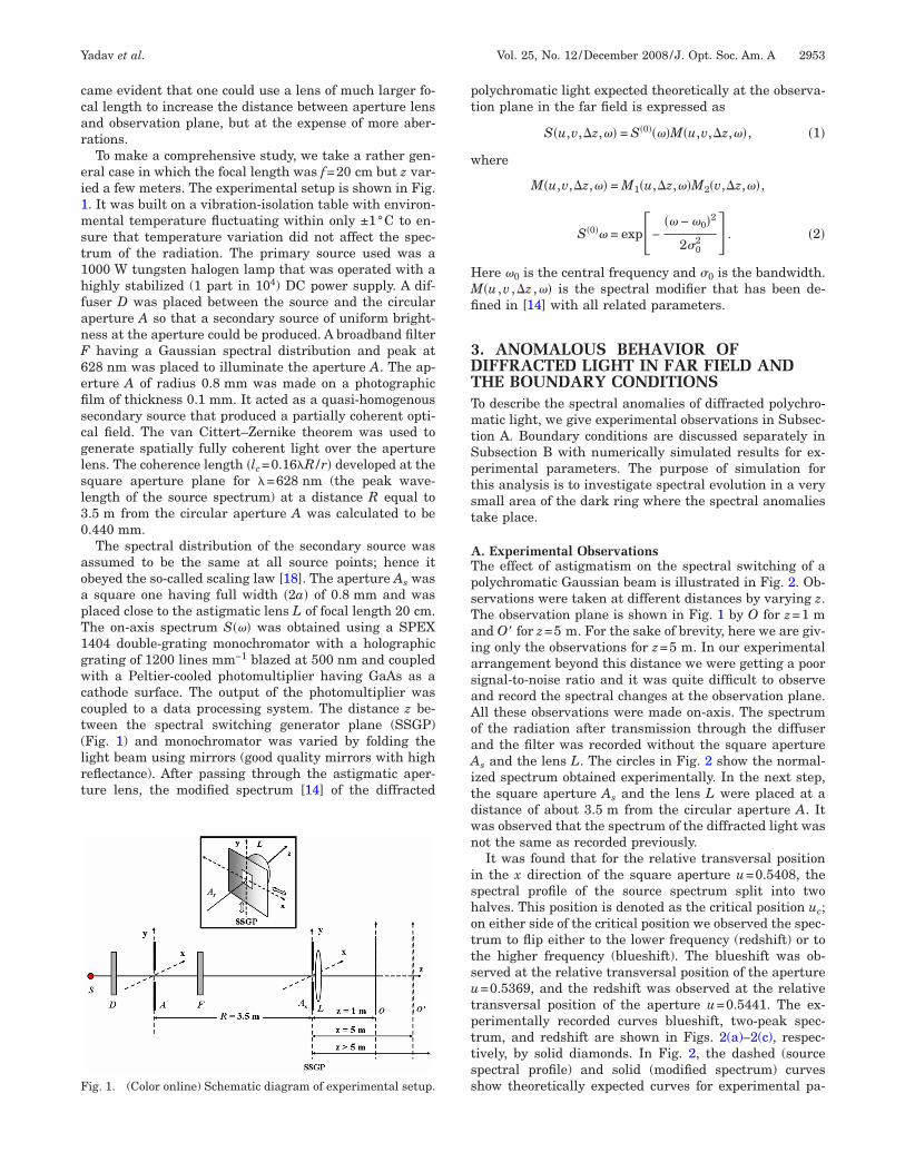
To make a comprehensive study, we take a rather gen-ral case in which the focal length was f=20 cm but z var-ed a few meters. The experimental setup is shown in Fig.. It was built on a vibration-isolation table with environ-ental temperature fluctuating within only ±1°C to en-
ure that temperature variation did not affect the spec-rum of the radiation. The primary source used was a000 W tungsten halogen lamp that was operated with aighly stabilized (1 part in 104) DC power supply. A dif-
user D was placed between the source and the circularperture A so that a secondary source of uniform bright-ess at the aperture could be produced. A broadband filterhaving a Gaussian spectral distribution and peak at
28 nm was placed to illuminate the aperture A. The ap-rture A of radius 0.8 mm was made on a photographiclm of thickness 0.1 mm. It acted as a quasi-homogenousecondary source that produced a partially coherent opti-al field. The van Cittert–Zernike theorem was used toenerate spatially fully coherent light over the apertureens. The coherence length �lc=0.16�R /r� developed at thequare aperture plane for �=628 nm (the peak wave-ength of the source spectrum) at a distance R equal to.5 m from the circular aperture A was calculated to be.440 mm.The spectral distribution of the secondary source was
ssumed to be the same at all source points; hence itbeyed the so-called scaling law [18]. The aperture As wassquare one having full width �2a� of 0.8 mm and was
laced close to the astigmatic lens L of focal length 20 cm.he on-axis spectrum S��� was obtained using a SPEX404 double-grating monochromator with a holographicrating of 1200 lines mm−1 blazed at 500 nm and coupledith a Peltier-cooled photomultiplier having GaAs as a
athode surface. The output of the photomultiplier wasoupled to a data processing system. The distance z be-ween the spectral switching generator plane (SSGP)Fig. 1) and monochromator was varied by folding theight beam using mirrors (good quality mirrors with higheflectance). After passing through the astigmatic aper-ure lens, the modified spectrum [14] of the diffracted
ig. 1. (Color online) Schematic diagram of experimental setup.
olychromatic light expected theoretically at the observa-ion plane in the far field is expressed as
S�u,v,�z,�� = S�0����M�u,v,�z,��, �1�
here
M�u,v,�z,�� = M1�u,�z,��M2�v,�z,��,
S�0�� = exp�−�� − �0�2
2�02 � . �2�
ere �0 is the central frequency and �0 is the bandwidth.�u ,v ,�z ,�� is the spectral modifier that has been de-
ned in [14] with all related parameters.
. ANOMALOUS BEHAVIOR OFIFFRACTED LIGHT IN FAR FIELD ANDHE BOUNDARY CONDITIONSo describe the spectral anomalies of diffracted polychro-atic light, we give experimental observations in Subsec-
ion A. Boundary conditions are discussed separately inubsection B with numerically simulated results for ex-erimental parameters. The purpose of simulation forhis analysis is to investigate spectral evolution in a verymall area of the dark ring where the spectral anomaliesake place.
. Experimental Observationshe effect of astigmatism on the spectral switching of aolychromatic Gaussian beam is illustrated in Fig. 2. Ob-ervations were taken at different distances by varying z.he observation plane is shown in Fig. 1 by O for z=1 mnd O� for z=5 m. For the sake of brevity, here we are giv-ng only the observations for z=5 m. In our experimentalrrangement beyond this distance we were getting a poorignal-to-noise ratio and it was quite difficult to observend record the spectral changes at the observation plane.ll these observations were made on-axis. The spectrumf the radiation after transmission through the diffusernd the filter was recorded without the square apertures and the lens L. The circles in Fig. 2 show the normal-
zed spectrum obtained experimentally. In the next step,he square aperture As and the lens L were placed at aistance of about 3.5 m from the circular aperture A. Itas observed that the spectrum of the diffracted light wasot the same as recorded previously.It was found that for the relative transversal position
n the x direction of the square aperture u=0.5408, thepectral profile of the source spectrum split into twoalves. This position is denoted as the critical position uc;n either side of the critical position we observed the spec-rum to flip either to the lower frequency (redshift) or tohe higher frequency (blueshift). The blueshift was ob-erved at the relative transversal position of the aperture=0.5369, and the redshift was observed at the relative
ransversal position of the aperture u=0.5441. The ex-erimentally recorded curves blueshift, two-peak spec-rum, and redshift are shown in Figs. 2(a)–2(c), respec-ively, by solid diamonds. In Fig. 2, the dashed (sourcepectral profile) and solid (modified spectrum) curveshow theoretically expected curves for experimental pa-

rvatst
BTts�==cccdc
cort0pFms3at(mugtsct
[=gntbtSrst(
ohptmftp
F(redshift.
2954 J. Opt. Soc. Am. A/Vol. 25, No. 12 /December 2008 Yadav et al.
ameters using Eq. (1). The spectral changes occur in theicinity of the first dark fringe of the diffraction patternnd in a very narrow range of �u from the critical posi-ion. It was observed that a very small change in the po-ition of the aperture leads to drastic spectral changes athe observation plane.
. Spectral Evolution and Boundary Conditionsheoretically expected curves using Eq. (1) for experimen-
al parameters are given in Fig. 3. To generate the sourcepectrum, the angular frequency � is varied from �=2.71015 to 3.3�1015 s−1. Here the central frequency is �03.0�1015 s−1, C6=0 mm−1, and the bandwidth is �06.0�1013 s−1. For blueshifts [Fig. 3(a)], u (transversaloordinate in the x direction) is varied from 0.5358 (solidurve) to 0.5379 (short-dashed curve). Experimentally, byhanging the position of the square aperture As in the xirection with a precise digital micrometer one canhange the value of u.
For the sake of convenience and to determine boundaryonditions, we may assume that if the height of the sec-nd peak (SP) of the modified spectrum (after diffraction)ises from 0 to 90% (0.9) of the normalized source spec-rum (reference spectrum) by changing u from 0.5358 to.5379, we may consider it a blueshift region. The firsteak (FP) and SP of the modified spectrum are shown inig. 3. The blueshift region may be considered the maxi-um spectral shift toward higher frequencies with re-
pect to the reference spectrum (source spectrum). In Fig.(a), the blueshift region is indicated by two vertical par-llel dotted–dashed lines with upward arrows. Rf denoteshe central reference line on the reference spectrumsource spectrum), while BS indicates the central line for
aximum (acceptable) spectral shift (blueshift), i.e., for=0.5379. WBSR represents the width of the blueshift re-ion. Beyond this limit, the blueshifted spectrum headsoward the two-equal-peaks spectrum (see below). Anypectrum falling in this region for a particular value of uan be treated as a blueshifted spectrum and may be usedo designate information bit 0, for example.
In the same manner, we may assign a redshift regionFig. 3(c)] from u=0.5430 (short dashed curve) to u0.5451 (solid curve). Again, any spectrum from this re-ion for a particular value of u may be chosen for desig-ating information bit 1. Here, WRSR denotes the width ofhe redshift region, while RS and Rf represent redshiftoundary line and the reference line, respectively. WRSR ishe maximum spectral shift toward lower frequencies.ome spectra for different values of u for blueshift andedshift in each region are shown in Fig. 3(a) and 3(c), re-pectively. In these figures, Hv denotes the height varia-ion zone for the second peak of the modified spectrumblueshift or redshift).
Figure 3(b) shows a special condition for a critical valuef uc=0.5408, where the source spectrum splits into twoalves. This spectrum may be termed the “two-equal-eaks” spectrum, where both peaks of the modified spec-rum are nearly equal in height. Experimentally, it is al-ost impossible to get two peaks exactly equal in height
or this spectrum; hence, we may accept a 10% uncer-ainty. If the heights of the two peaks of the two-equal-eaks spectrum are no further apart than 10% of the
ig. 2. Experimentally observed spectral switching at z=5 m:a) blueshift, (b) TPD spectrum in critical direction, and (c)

hro
4SCFpapoctsdpdadoma
AFsdvsdrspd
tahiwtTtSd
Fstions for (a) blueshift, (b) TPD spectrum, (c) and redshift.
Fp
Yadav et al. Vol. 25, No. 12 /December 2008 /J. Opt. Soc. Am. A 2955
igher peak value [within what we call the uncertaintyegion (UR)], we may consider them two equal peaks forur purposes here.
. FREE-SPACE OPTICAL LINKS FORPECTRAL-SWITCHING-BASED OPTICALOMMUNICATIONoley and Wolf have shown that the spectral switchinghenomenon is closely related to phase singularities [5],nd Gbur et al. that the drastic spectral changes takelace in the vicinity of an intensity zero in the focal regionf a polychromatic, spatially coherent, converging spheri-al wave [19]. Simultaneously, it has been demonstratedhat the spectral changes occur in the neighborhood ofome special directions—which may be called “criticalirections”—associated with the dark rings of the Airyattern in the Fraunhofer region of a field produced byiffraction of a spatially coherent, polychromatic wave atn aperture [20]. The critical directions along with theark fringes of diffraction patterns may be used to formptical links. The self-similarity of the far-zone spectrumay make it possible to transmit optical information over
ppreciable distances.
. Free-Space Optical Links in Fraunhofer Diffractionree-space optical links in Fraunhofer diffraction arehown in Fig. 4. The figure also shows propagation of theiffraction pattern along with the critical directions in theicinity of dark rings. Here O1, O2, and O3 show the first,econd, and third critical directions, respectively. As theiffracted light field propagates in free space, the effectiveegion (ER) (around the singular point) where the blue-hift, two-equal-peaks spectrum, and the redshift takelace expands to a very small extent around the criticalirection.To obtain a better understanding of the internal struc-
ure of the diffracted light field, let us hypothetically takelongitudinal and a transverse cross section of the upperemisphere of the first dark ring. The schematic diagram
s shown in Fig. 5. RSD and BSD indicate the directionshere the redshift and the blueshift occur after diffrac-
ion of polychromatic light through the aperture, whileDP (between them) shows the critical direction where
he source spectrum splits into two halves. In this figure,is the polychromatic light source, and ORSR shows the
irection of propagation (z axis).
ig. 4. Optical field propagation in far field after diffractionattern.
ig. 3. Simulated curves for experimental parameters to under-tand the spectral evolution and to determine boundary condi-

itvspfirgecpthrtd
loptlwtccbl
tcwtaswccl
BRs
Gadvoada
tmathbtddm
nsmti
omstgdd
5ISRp[dttlcti
Ft
Fact
2956 J. Opt. Soc. Am. A/Vol. 25, No. 12 /December 2008 Yadav et al.
All the directions are imaginary, but the investigationndicates that the spectral changes (as discussed in Sec-ion 3) take place around these directions. The ER is aery small region (almost a point) in the near field but itpreads to a very small extent with distance duringropagation along the z axis (the direction of diffractioneld propagation). Because of this spreading the blueshiftegion �WBSR�, two-equal-peaks region, and redshift re-ion �WRSR� also spread and become sufficiently broad-ned in the far field to make it easy to resolve the spectralhanges. To illustrate the concept, the redshift, two-equal-eaks region, and blueshift regions are shown by sub-ended areas in Fig. 5 from point OR to the RSD (crossatching), TPD (dark gray), and BSD (vertical hatching),espectively. The imaginary direction along with the sub-ended area (where the spectral anomalies occur) of eachirection may be treated as the free-space optical link.Apart from the demonstration of the free-space optical
ink, Fig. 5 also gives a glimpse of the complex structuref the light radiation near a phase singularity [19] and itsropagation in free space. It has already been shown thathe spectral anomalies also take place in a small circularoop around the TPD. To show the concept a small circleith broad arrow band is shown behind the dark ring on
he critical direction (TPD). The spectral changes also oc-ur by changing the polar angle � associated with thisircle. The spectral changes with � [12] and the relationetween the diffraction angle � (not shown here) and po-ar angle � have previously been demonstrated [20].
It should be noted that for the experimental observa-ions discussed in Subsection 3.A and [17], the spectralhanges and construction of the free-space optical linkould be considered in transverse cross section (Fig. 5) in
he related dark ring, because in these observations were changing the position coordinate u to produce spectralwitching. In other typical experimental observationshere spectral switching is controlled by changing spatial
oherence [7,8] and diffraction angle [12], a longitudinalross section will be effective to observe spectral anoma-ies and to form the free-space optical link.
. Free-Space Optical Link in Hollow Gaussian Beamecently, it has been demonstrated theoretically [21] thatpectral switching can be observed in a focused hollow
ig. 5. Schematic diagram to illustrate the internal structure offree-space optical link. It shows longitudinal and transverse
ross sections of the upper part of the first dark ring. O indicateshe observation plane.
aussian beam (HGB). The HGB may be ideal to createn optical link due to its interesting properties. Figure 6epicts a schematic diagram of a free-space optical linkia HGB. In this scheme the optical link lies in the centerf the HGB. Again the redshift, two-equal-peaks region,nd the blueshift region are shown by cross hatching,ark gray shade, and vertical hatching, respectively,long with the critical direction.The most interesting aspect of the HGB is the light in-
ensity distribution around the free-space optical link. Itay act as a shield for the free-space optical link against
tmospheric turbulence. The propagation properties ofhe HGB have already been studied theoretically, and itas been shown that the HGB has good propagation sta-ility in the near zone. With further increase of propaga-ion distance z the intensity distribution diverges and theark region across the HGB decreases. In the far field, theark region disappears and the on-axis intensity becomesaximum [22].The above investigations reveal that despite the HGB
ot being entirely suitable for larger distances, a free-pace optical link may be created for distances of a feweters. Future technological advancement may increase
his possibility multifold. Experimental work on this topics underway and will soon be reported elsewhere.
While analyzing spectral-switching-based free-spaceptical communication from a few centimeters to a feweters (maximum up to 5 m), we have not taken atmo-
pheric turbulence into account, as for such shorter dis-ances, the atmospheric turbulence will be almost negli-ible. It has already been demonstrated that for largeristances atmospheric turbulence affects the light beamuring propagation in free space [23].
. SPECTRAL-SWITCHING-BASEDNFORMATION ENCODING AND FREE-PACE OPTICAL COMMUNICATIONecent research shows that spectral switching may be ex-loited for information encoding and transmission11–13]. Information encoding schemes have already beeniscussed in detail but spectral-switching-based informa-ion transmission has not yet been treated in detail. Inhis section, we discuss the possibilities and experimentalimitations for spectral-switching-based free-space opticalommunication. The analysis is based on the experimen-al and theoretical investigations carried out to date. Thenvestigation may be quite significant as spectral-
ig. 6. Free-space optical link through HGB between transmit-er and receiver.
stf
tltccfcwas
AAmFct(soSssht
rtcrchcbItltc
BTt8bniis�T
CTewtmssis
i
n
tem
fsdup
mtrs
Yadav et al. Vol. 25, No. 12 /December 2008 /J. Opt. Soc. Am. A 2957
witching-based optical communication may be exploitedo design free-space optical interconnects [24] and evenree-space optical communication [25].
We give a general analysis that may be useful for bothypes of applications. Despite some typical experimentalimitations, spectral-switching-based optical communica-ion has some interesting advantages over other opticalommunication systems. It may provide a new way ofommunication. To explore possibilities, a general modelor spectral-switching-based free-space optical communi-ation is proposed and discussed. To ensure consistencyith experimental observations, the experimental datare used for the information encoding and processingcheme.
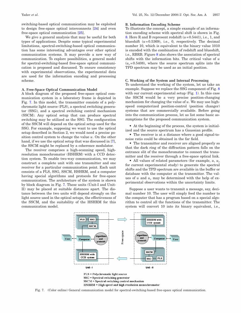
. Free-Space Optical Communication Modelblock diagram of the proposed free-space optical com-unication system in a laboratory frame is depicted inig. 7. In this model, the transmitter consists of a poly-hromatic light source (PLS), a spectral switching genera-or (SSG), and a spectral switching control mechanismSSCM). Any optical setup that can produce spectralwitching may be utilized as the SSG. The configurationf the SSCM will depend on the optical setup used for theSG. For example, supposing we want to use the opticaletup described in Section 2, we would need a precise po-ition control system to change the value u. On the otherand, if we use the optical setup that was discussed in [7],he SSCM might be replaced by a coherence modulator.
The receiver comprises a high-scanning speed, high-esolution monochromator (HSHRM) with a CCD detec-ion system. To enable two-way communication, we mayonstruct a complete unit with one transmitter and oneeceiver for a particular communication point. Each unitonsists of a PLS, SSG, SSCM, HSHRM, and a computeraving special algorithms and protocols for free-spaceommunication. The architecture of the system is showny block diagram in Fig. 7. These units (Unit-I and Unit-I) may be placed at suitable distances apart. The dis-ance between the two units will depend strongly on theight source used in the optical setups, the effectiveness ofhe SSCM, and the suitability of the HSHRM for thisommunication model.
Fig. 7. (Color online) General communication model fo
. Information Encoding Schemeo illustrate the concept, a simple example of an informa-ion encoding scheme with spectral shift is shown in Fig.. Here R and B represent redshift �u=0.5441�, i.e., 1, andlueshift �u=0.5369�, i.e., 0, respectively. The decimalumber 10, which is equivalent to the binary value 1010
s encoded with the combination of redshift and blueshift,.e., RBRB. Figure 8 also shows the association of spectralhifts with the information bits. The critical value of uuc=0.5408�, where the source spectrum splits into thePD spectrum may be used as an initial position.
. Working of the System and Internal Processingo understand the working of the system, let us take anxample. Suppose we replace the SSG component of Fig. 8ith our current experimental setup (Fig. 1). In this case
he SSCM would be a very precise position-changingechanism for changing the value of u. We may use high-
peed computerized position-control (position changer)ystems that are commercially available. Before goingnto the communication process, let us list some basic as-umptions for the proposed communication system.
• At the beginning of the process, the system is initial-zed and the source spectrum has a Gaussian profile.
• The receiver is at a distance where a good signal-to-oise ratio could be obtained in the far field.• The transmitter and receiver are aligned properly so
hat the dark ring of the diffraction pattern falls on thentrance slit of the monochromator to connect the trans-itter and the receiver through a free-space optical link.• All values of related parameters (for example, u, uc
or current experimental study) to generate the spectralhifts and the TPD spectrum are available in the buffer oratabase with the computer at the transmitter. The val-es of u and uc may be determined with the help of ex-erimental observations within the uncertainty limits.
Suppose a user wants to transmit a message, say, deci-al number 10. The user will simply feed the number to
he computer that has a program based on a special algo-ithm to control all the functions of the transmitter. Theystem will convert 10 into its binary equivalent, i.e.,
tral-switching-based free-space optical communication.
r spec
�iitfti
t=bSvtrwiiwvfwo
wdcmcrc(in
DCItoa
bd
otmt
r(tehp
t
ETsctl
scwt
ltan
wt
foistfrefcct
6IsDwbtssmmt
Fs
2958 J. Opt. Soc. Am. A/Vol. 25, No. 12 /December 2008 Yadav et al.
10�2=1010 and associated information bits as discussedn Subsection 5.B. Now the system is ready to process thenformation optically using the free-space optical link inhe far field. For convenience, let us designate the planeormed by the aperture As with lens L to generate spec-ral switching by the SSGP. A 3-D schematic of the SSGPs shown in the inset of Fig. 1.
The system starts processing (left to right) and takeshe first spectral shift R from the message string �10RBRB� that has corresponding value u=0.5441 in theuffer of the system. Immediately, a signal goes to theSCM to adjust the position of the SSGP for the givenalue of u. As a result of the repositioning of the SSGP,he source spectrum will be modified and the receiver willead the redshifted spectrum. In the next step, the SSGPill automatically readjust itself for the initial position,
.e., uc=0.5408. It should be noted here that we are chang-ng the position (very precisely) of square aperture Ashile the lens L is fixed at the SSGP. The same process ofalue selection and spectral shift generation will continueor each value of u until the transmitter transmits thehole string (message) to the receiver over the free-spaceptical link.
Simultaneously, the spectra reaching the receiver planeill be recorded by means of the HSHRM. A sophisticatedecoding algorithm may be used here to process the re-orded spectra. It is the function of the receiver to deter-ine the nature of each spectral shift (whether the re-
orded spectrum is redshifted or blueshifted). Theeceiver records the spectral shifts and simultaneouslyonverts them into their corresponding information bitsredshift=1 and blueshift=0). The converted sequences ofnformation bits are finally used to regenerate the origi-al message.
. Advantages of Spectral-Switching-Based Opticalommunicationnformation encoding and transmission in free spacehrough spectral switching has some advantages overther optical communication systems. Some significantdvantages are listed below.
1. In the proposed scheme, the information is encodedy spectral shifts; any fluctuations in the light intensityo not cause errors in bit transmission. Moreover, because
ig. 8. (Color online) Concept of information encoding withpectral switching.
f the symmetry of the spectral shifts in the far field alonghe axis, the information can be transmitted to two sym-etrical points at which the amount of spectral shifts is
he same [11].2. Apart from the information bits’ association with
edshift and blueshift one can entangle information bitsfor example, 10) using the TPD spectrum [12]. The en-angled bits provide an additional degree of freedom toncode information (1, 0, and 10). This may certainly en-ance the throughput of the information transmissionrocess.3. Entangled bits may also be used as a special condi-
ion to conceal the information [13].
. Limitations of the Proposed Schemehe spectral-switching-based optical communicationcheme is at an experimental stage and it has some typi-al experimental constraints that may be addressed inhe near future. Some important limitations are listed be-ow.
• Although the diffraction pattern maintains its self-imilarity and the information could be sent over appre-iable distances, the signal-to-noise ratio at the far zoneill affect the quality of transmission beyond certain dis-
ances.• A good broadband light source (like a so-called white
ight laser) is the prime requirement of the communica-ion system to send information for longer distances. Suchbroadband source may be commercially available in theear future.• Atmospheric turbulence will be a serious threat
hen we consider optical communication for larger dis-ances.
• In the present scenario, speed may be a major issueor such systems. On the transmitter side, if we use theptical setup discussed in [7], fast coherence modulations required to generate spectral switching with highpeed. For this system, the maximum coherence modula-ion speed may be 1 �s. This is the best speed attained soar for the coherence modulation technique [26]. On theeceiver side, on the other hand, the situation is not veryncouraging as the best scanning speed (demonstrated soar) is only 1000 nm/s �60,000 nm/min�. Because of theseonstraints, at this stage the proposed scheme cannot beompared speedwise with modern ultrafast communica-ion schemes.
. CONCLUSIONn this paper we have discussed experimental results forpectral switching of polychromatic light in the far zone.ifferent optical links in the vicinity of dark rings, alongith the critical direction near a phase singularity, haveeen discussed in detail. The results of the study indicatehat if we have a broadband light source with high inten-ity, the spectral switching could be controlled with highpeed and accuracy in a predefined manner within experi-ental uncertainty, and if we have a very high-resolutiononochromator with high scanning speed, the informa-
ion encoding and transmission using spectral switching

mfihpsp
ATrpat
R
1
1
1
1
1
1
1
1
1
1
2
2
2
2
2
2
2
Yadav et al. Vol. 25, No. 12 /December 2008 /J. Opt. Soc. Am. A 2959
ay be realizable for the near field as well as for the fareld. Unfortunately, this is not so easy at this stage, but itas great potential for implementation. Realization of theroposed scheme may take the passage of time, but thetudy may be quite significant as these techniques mayrovide a new way for free-space optical communication.
CKNOWLEDGMENTShe authors thank the Director, National Physical Labo-atory, New Delhi, India for permission to publish this pa-er. S. Raman is also thankful to Council for Scientificnd Industrial Research (CSIR) for financial support inhe form of a Senior Research Fellowship.
EFERENCES1. J. Pu, H. Zhang, and S. Nemoto, “Spectral shifts and
spectral switches of partially coherent light passingthrough an aperture,” Opt. Commun. 162, 57–63 (1999).
2. J. Pu and S. Nemoto, “Spectral shifts and spectral switchesin diffraction of partially coherent light by a circularaperture,” IEEE J. Quantum Electron. 36, 1407–1411(2000).
3. L. Pan and B. Lu, “The spectral switch of partially coherentlight in Young’s experiment,” IEEE J. Quantum Electron.37, 1377–1381 (2001).
4. J. Pu and S. Nemoto, “Spectral changes and 1�N spectralswitches in the diffraction of partially coherent light by anaperture,” J. Opt. Soc. Am. A 19, 339–344 (2002).
5. J. T. Foley and E. Wolf, “Phenomenon of spectral switchesas a new effect in singular optics with polychromatic light,”J. Opt. Soc. Am. A 19, 2510–2516 (2002).
6. H. C. Kandpal, “Experimental observation of thephenomenon of spectral switch” J. Opt. A, Pure Appl. Opt.3, 296–299 (2001).
7. H. C. Kandpal, S. Anand, and J. S. Vaishya, “Experimentalobservation of the phenomenon of spectral switching for aclass of partially coherent light,” IEEE J. QuantumElectron. 38, 336–339 (2002).
8. S. Anand, B. K. Yadav, and H. C. Kandpal, “Experimentalstudy of the phenomenon of 1�N spectral switch due todiffraction of partially coherent light,” J. Opt. Soc. Am. A19, 2223–2228 (2002).
9. B. K. Yadav, S. A. M. Rizvi, and H. C. Kandpal,“Experimental observation of spectral changes of partiallycoherent light in Young’s experiment,” J. Opt. A, Pure Appl.
Opt. 8, 72–76 (2006).0. M. M. Brundavanam, N. K. Viswanathan, and N. R. Desai,“Spectral anomalies due to temporal correlation in a white-light interferometer,” Opt. Lett. 32, 2279–2281 (2007).
1. J. Pu, C. Cai, and S. Nemoto, “Spectral anomalies inYoung’s double-slit interference experiment,” Opt. Express12, 5131–5139 (2004).
2. B. K. Yadav, S. A. M. Rizvi, S. Raman, R. Mehrotra, and H.C. Kandpal, “Information encoding by spectral anamolies ofspatially coherent light diffracted by an annular aperture,”Opt. Commun. 269, 253–260 (2007).
3. B. K. Yadav, N. S. Bisht, R. Mehrotra, and H. C. Kandpal,“Diffraction-induced spectral anomalies for informationencoding and information hiding—possibilities andlimitations,” Opt. Commun. 277, 24–32 (2007).
4. L. Pan and B. Lu, “Spectral switches of polychromaticGaussian beams passing through an astigmatic aperturelens,” Opt. Commun. 234, 13–22 (2004).
5. J. Pu, C. Cai, and S. Nemoto, “Spectral switches of partiallycoherent light focused by a filter-lens system withchromatic aberration,” J. Opt. Soc. Am. A 21, 994–999(2004).
6. X. Hu and J. Pu, “The effect of spherical aberration onsingularities and spectral changes of focused beams,” NewJ. Phys. 8, 93 (2006).
7. S. Raman, N. S. Bisht, B. K. Yadav, R. Mehrotra, M.Husain, and H. C. Kandpal, “Experimental observation ofthe effect of astigmatic aperture lens on the spectralswitches of polychromatic Gaussian beam,” J. Mod. Opt.55, 1629–1638 (2008).
8. E. Wolf, “Invariance of the spectrum of light onpropagation,” Phys. Rev. Lett. 56, 1370–1372 (1986).
9. G. Gbur, T. D. Visser, and E. Wolf, “Anomalous behavior ofspectra near phase singularities of focused waves,” Phys.Rev. Lett. 88, 013901 (2001).
0. S. A. Ponomarenko and E. Wolf, “Spectral anomalies in aFraunhofer diffraction pattern,” Opt. Lett. 27, 1211–1213(2002).
1. H. Zhang, G. Wu, and H. Guo, “Spectral anomalies offocused hollow Gaussian beams at the geometrical focalplane,” Opt. Commun. 281, 4169–4172 (2008).
2. Y. Cai, X. Lu, and Q. Lin, “Hollow Gaussian beams andtheir propagation properties,” Opt. Lett. 28, 1084–1086(2003).
3. H. T. Eyyuboglu, Y. Cai, and B. K. Baykal, “Spectral shiftsof general beams in turbulent media,” J. Opt. A, Pure Appl.Opt. 10, 015005 (2008).
4. T. Yatagai, S. Kawai, and H. Huang, “Optical computingand interconnects,” Proc. IEEE 84, 828–852 (1996).
5. Dominic O’Brien, “Free-space optical links for broadbandwireless communication,” http://www.acreo.se/upload/Publications/Proceedings/OE03/FREESPACE-OE003.pdf.
6. J. Turunen, E. Tervonen, and A. T. Friberg, “Acousto-opticcontrol and modulation of optical coherence byelectronically synthesized holographic grating,” J. Appl.
Phys. 67, 49–59 (1990).